
Optimal Magnetic Graphite Heater Design for Impurity Control in Single-Crystal Si Grower Using Crystal Growth Simulation

 , ,
, ,
Abstract
:1. Introduction
2. Methods
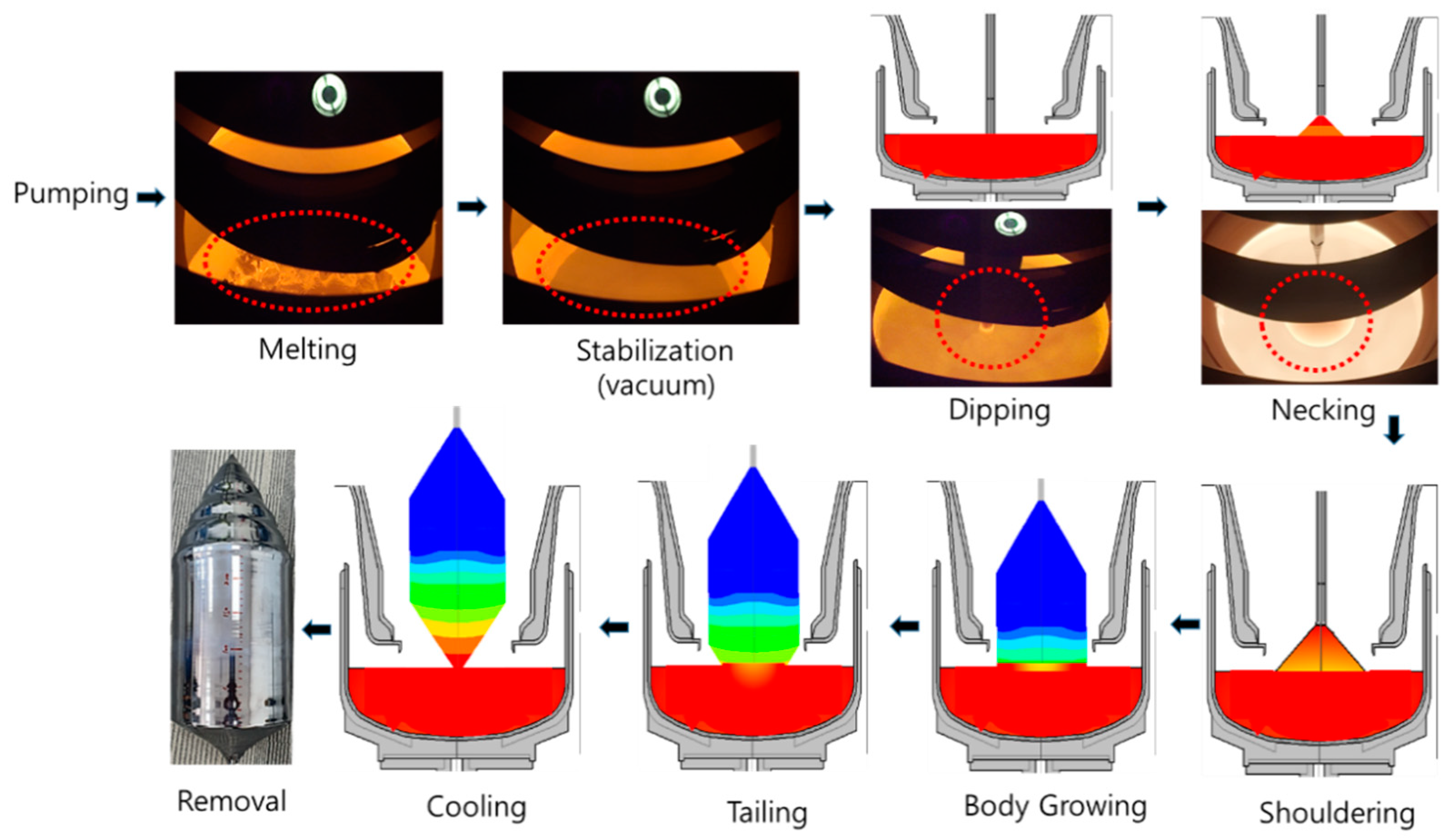
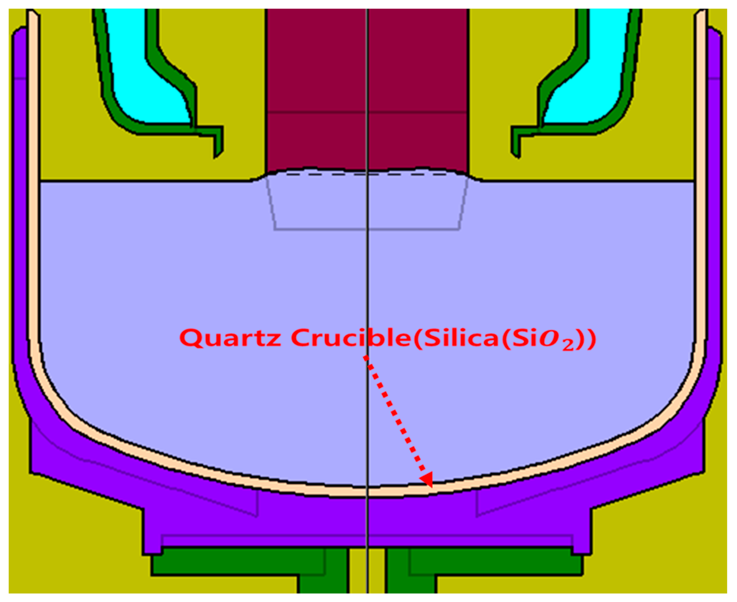
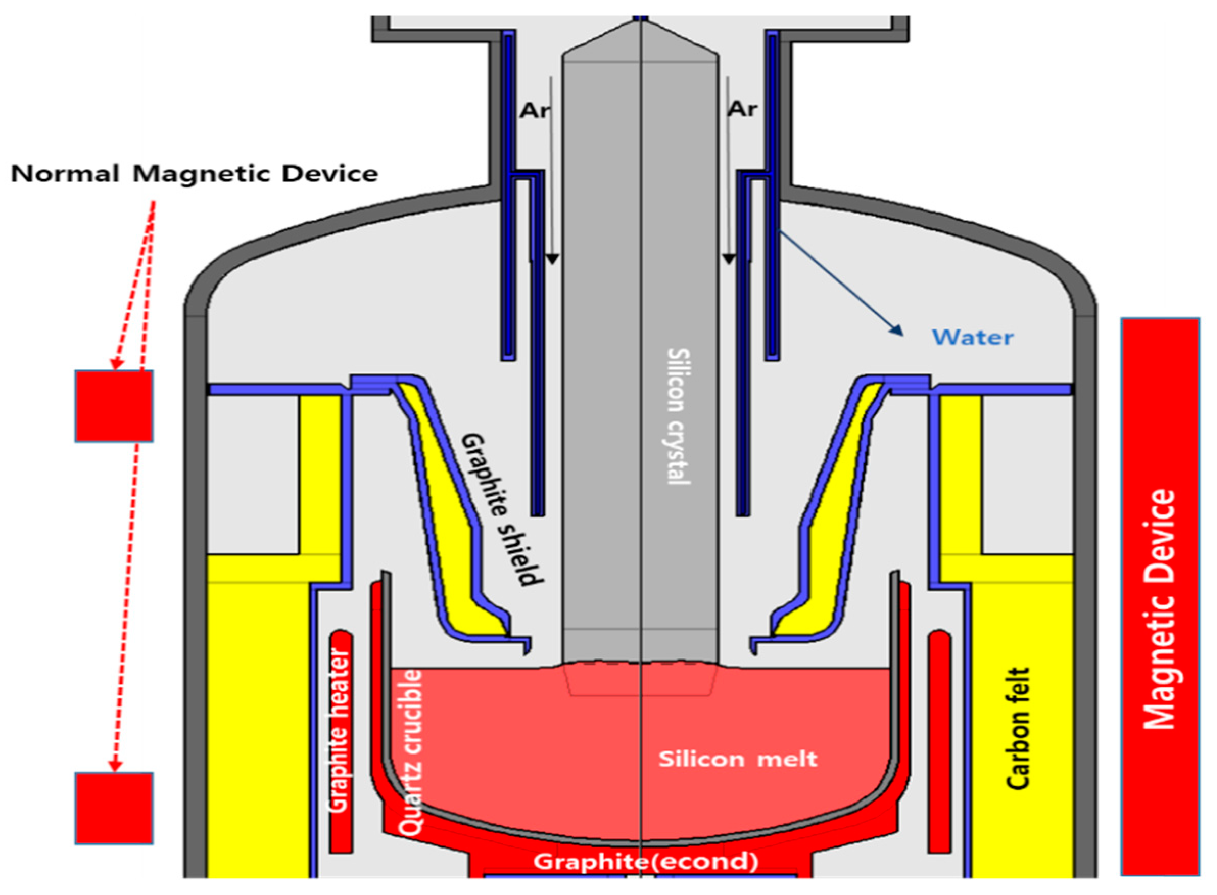
2.1. Process and Mathematical Modeling
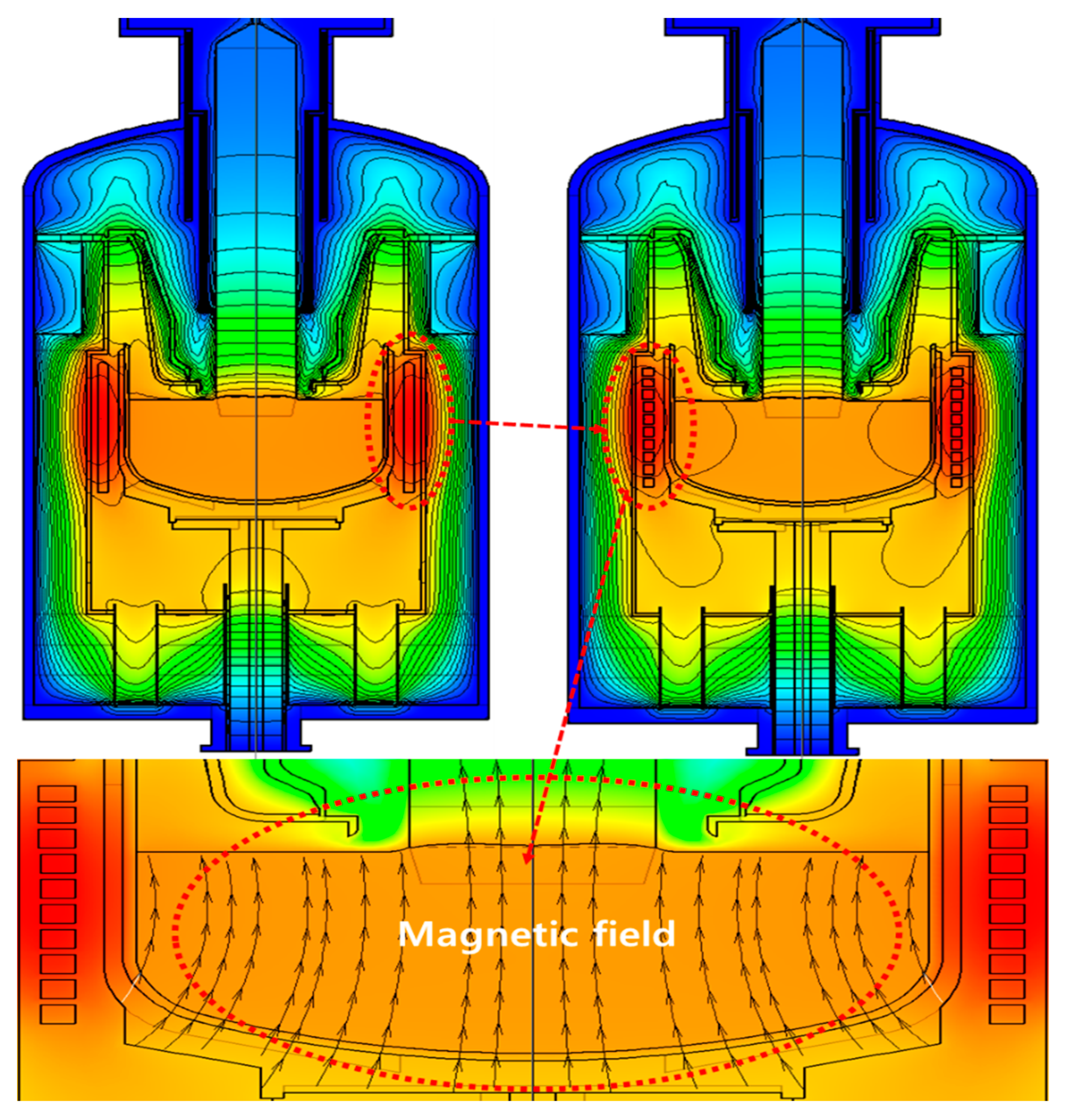
2.2. Motivation of Impurities
3. Results and Discussion
4. Conclusions
Author Contributions
Funding
Institutional Review Board Statement
Informed Consent Statement
Data Availability Statement
Conflicts of Interest
Software
References
- Park, D.; Kim, M.; So, W.; Oh, S.-Y.; Park, H.; Jang, S.; Park, S.-H.; Kim, W.K. Evaluation of Bifacial Si Solar Module with Different Albedo Conditions. Curr. Photovolt. Res. 2018, 6, 62–67. [Google Scholar] [CrossRef]
- Chen, Q.; Jiang, Y.; Yan, J.; Qin, M. Progress in modeling of fluid flows in crystal growth processes. Prog. Nat. Sci. 2008, 18, 1465–1473. [Google Scholar] [CrossRef]
- Deai, H.; Iwasaki, T.; Ikematsu, Y.; Kawakami, K.; Harada, H.; Matsumura, A. Influence of crystal originated particles on gate oxide breakdown. Jpn. J. Appl. Phys. 1996, 35, 1476–1479. [Google Scholar] [CrossRef]
- Friedrich, J.; von Ammon, W.; Müller, G. Czochralski growth of silicon crystals. In Handbook of Crystal Growth; Elsevier: Amsterdam, The Netherlands, 2014; pp. 45–104. [Google Scholar]
- Wang, C.; Zhang, H.; Wang, T.; Ciszek, T. A continuous Czochralski silicon crystal growth system. J. Cryst. Growth 2003, 250, 209–214. [Google Scholar] [CrossRef]
- Fisher, G.; Searist, M.R.; Standley, R.W. Silicon Crystal Growth and Wafer Technologies. Proc. IEEE 2012, 100, 1454–1474. [Google Scholar] [CrossRef]
- Von Ammon, W.; Gelfgat, Y.; Gorbunov, L.; Muhlbauer, A.; Muiznieks, A.; Makarov, Y.; Virbulis, J.; Muller, G. Application of magnetic fields in industrial growth of silicon single crystals. In Proceedings of the Joint 15th Riga and 6th PAMIR International Conference on Fundamental and Applied MHD, Rigas, Latvia, 27 June–1 July 2005; pp. 41–45. [Google Scholar]
- Kalaev, V.; Sattler, A.; Kadinski, L. Crystal twisting in Cz Si growth. J. Cryst. Growth 2015, 413, 12–16. [Google Scholar] [CrossRef]
- Zhao, W.; Li, J.; Liu, L. Control of Oxygen Impurities in a Continuous-Feeding Czochralski-Silicon Crystal Growth by the Double-Crucible Method. Crystals 2021, 11, 264. [Google Scholar] [CrossRef]
- Voronkov, V.-V.; Falster, R. Vacancy-type microdefect formation in Czochralski silicon. J. Cryst. Growth 1998, 194, 76–88. [Google Scholar] [CrossRef]
- Hirata, H.; Hoshikawa, K. Silicon crystal growth in a cusp magnetic field. J. Cryst. Growth 1989, 96, 747–755. [Google Scholar] [CrossRef]
- Ding, J.; Li, Y.; Liu, L. Effect of cusp magnetic field on the turbulent melt flow and crystal/melt interface during large-size Czochralski silicon crystal growth. Int. J. Therm. Sci. 2021, 170, 107137. [Google Scholar] [CrossRef]
- Collet, Y.; Magotte, O.; Van den Bogaert, N.; Rolinsky, R.; Loix, F.; Jacot, M.; Regnier, V.; Marchal, J.-M.; Durpet, F. Effective simulation of the effect of a transverse magnetic field (TMF) in Czochralski Silicon growth. J. Cryst. Growth 2012, 360, 18–24. [Google Scholar] [CrossRef]
- Frank-Rotsch, C.; Dropka, N.; Kießling, F.-M.; Rudolph, P. Semiconductor Crystal Growth under the Influence of Magnetic Fields. Cryst. Res. Technol. 2020, 55, 1900115. [Google Scholar] [CrossRef]
- Kakimoto, K.; Eguchi, M.; Ozoe, H. Use of an inhomogenous magnetic field for silicon crystal growth. J. Cryst. Growth 1997, 180, 442–449. [Google Scholar] [CrossRef]
- Huang, X.; Taishi, T.; Wang, T.; Hoshikawa, K. Measurement of temperature gradient in Czochralski silicon crystal growth. J. Cryst. Growth 2001, 229, 6–10. [Google Scholar] [CrossRef]
- Nam, W.; Hahn, Y.; Baik, S. Local optimization of graphite heater to save a power consumption of Czochralski Si ingot grower for PV application. Energy Procedia 2017, 124, 767–776. [Google Scholar] [CrossRef]
- Yokoyama, R.; Nakamura, T.; Sugimura, W.; Ono, T.; Fujiwara, T.; Kakimoto, K. Time-dependent behavior of melt flow in the industrial scale silicon Czochralski growth with a transverse magnetic field. J. Cryst. Growth 2001, 519, 77–83. [Google Scholar] [CrossRef]
- Naguyen, T.H.T.; Chen, J.-J.; Hu, C.; Chen, C.-H. Numerical simulation of heat and mass transfer during Czochralski silicon crystal growth under the application of crystal-crucible counter- and iso-rotations. J. Cryst. Growth 2019, 507, 50–57. [Google Scholar] [CrossRef]
- Seigneur, H.; Mohajeri, N.; Brooker, K.R.P.; Davis, O.; Schneller, E.J.; Dhere, N.G.; Rodgers, M.P.; Wohlgemuth, J.; Shiradkar, N.S.; Scardera, G.; et al. Manufacturing metrology for c-Si photovoltaic module reliability and durability, Part I: Feedstock, crystallization and wafering. Renew. Sustain. Energy Rev. 2016, 59, 84–106. [Google Scholar]
- Gaspar, G.M.M.; Autruffe, A.; Pó, J.-M. Silicon growth technologies for PV applications. In New Research on Silicon—Structure, Properties, Technology, Vitalyi Igorevich Talanin; IntechOpen: London, UK, 2017. [Google Scholar] [CrossRef] [Green Version]
- Phuc, L.T.H.; Jeon, H.; Truong, N.T.N.; Hak, J.J. Improving the Dipping Step in Czochraski Process Using Haar-Cascade Algorithm. Electronics 2019, 8, 646. [Google Scholar] [CrossRef] [Green Version]
- Kalaev, V.; Lukanin, D.; Zabelin, V.; Makarov, Y.N.; Virbulis, J.; Dornberger, E.; Von Ammon, W. Calculation of bulk defects in CZ Si growth: Impact of melt turbulent fluctuations. J. Cryst. Growth 2003, 250, 203–208. [Google Scholar] [CrossRef]
- Voronkov, V.; Falster, R. Vacancy and self-interstitial concentration incorporated into growing silicon crystals. J. Appl. Phys. 1999, 86, 5975–5982. [Google Scholar] [CrossRef]
- Mukaiyama, Y.; Sueoka, K.; Maeda, S.; Iizuka, M.; Mamedov, V.M. Numerical analysis of effect of thermal stress depending on pulling rate on behavior of intrinsic point defects in large-diameter Si crystal grown by Czochralski method. J. Cryst. Growth 2020, 531, 125334. [Google Scholar] [CrossRef]
- Sortland, Ø.-S.; Øvrelid, E.-J.; M’Hamdi, M.; Di Sabatino, M. Investigation of pinholes in Czochralski silicon ingots in relation to structure loss. J. Cryst. Growth 2019, 510, 1–6. [Google Scholar] [CrossRef]
- Shockley, W.; Read, W., Jr. Statistics of the recombinations of holes and electrons. Phys. Rev. Rev. 1952, 87, 835–842. [Google Scholar] [CrossRef]
- Forrest, E.C.; Hu, L.-W.; Buongiorno, J.; McKrell, T.J. Convective heat transfer in a high aspect ratio minichannel heated on one side. J. Heat Transf. 2016, 138, 021704. [Google Scholar] [CrossRef]
- Evstratov, I.Y.; Alaev, V.V.; Zhmakin, A.I.; Makarov, Y.N.; Abramov, A.G.; Ivanov, N.G.; Smirnov, E.M.; Dornberger, E.; Virbulis, J.; Tomzig, E.; et al. Modeling analysis of unsteady three-dimensional turbulent melt flow during Czochralski growth of Si crystals. J. Cryst. Growth 2001, 230, 22–29. [Google Scholar] [CrossRef]
- Patience, G.-S. Experimental Methods and Instrumentation for Chemical Engineers; Elsevier: Amsterdam, The Netherlands, 2013; pp. 227–263. [Google Scholar] [CrossRef]
- Lord Rayleigh, O.M.F.R.S. LIX.On convection currents in a horizontal layer of fluid, when the higher temperature is on the under side. Phil. Mag. 2009, 32, 529–546. [Google Scholar] [CrossRef] [Green Version]
- Çengel, Y.; Turner, R.; Cimbala, J. Fundamentals of Thermal-Fluid Sciences, 5th ed.; McGraw-Hill Education: New York, NY, USA, 2017; pp. 715–820. [Google Scholar]
- Squires, M.-T.; Quake, S.-R. Microfluidics: Fluid physics at the nanoliter scale. Rev. Mod. Phys. 2005, 77, 977–1026. [Google Scholar] [CrossRef] [Green Version]
- Patankar, S.-V. Numerical Heat Transfer and Fluid Flow; McGraw-Hill Education: New York, NY, USA, 1980; p. 715. [Google Scholar]
- Prostomolotov, A.-I.; Verezub, N.-A.; Mezhennii, M.-V.; Reznik, V.-Y. Thermal optimization of CZ bulk growth and wafer annealing for crystalline dislocation-free silicon. J. Cryst. Growth 2011, 318, 187–192. [Google Scholar] [CrossRef]
- Sim, B.-C.; Jung, Y.-H.; Lee, H.-W. Effect of the ingot cooling on the grown-in defects in silicon Czochralski growth. Jpn. J. Appl. Phys. 2009, 48, 105503. [Google Scholar] [CrossRef]
- Zhao, W.; Liu, L. Control of heat transfer in continuous-feeding Czochralski-silicon crystal growth with a water-cooled jacket. J. Cryst. Growth 2017, 458, 31–36. [Google Scholar] [CrossRef]
- Jeon, H.J.; Park, H.; Koyyada, G.; Alhammadi, S.; Jung, J.H. Optimal Cooling System Design for Increasing the Crystal Growth Rate of Single-Crystal Silicon Ingots in the Czochralski Process Using the Crystal Growth Simulation. Processes 2020, 8, 1077. [Google Scholar] [CrossRef]
- Fumio, S. Single-Crystal Silicon: Growth and Properties. In Springer Handbook of Electronic and Photonic Materials; Springer: Cham, Switzerland, 2017. [Google Scholar] [CrossRef] [Green Version]
- Digges, T.-G.; Shima, R. The Effect of Growth Rate, Diameter and Impurities Concentration on structure Czochralski silicon crystal growth. J. Cryst. Growth 1980, 50, 865–869. [Google Scholar] [CrossRef]
- Kulkarni, M.S. Defect dynamics in the presence of oxygen in growing Czochralski silicon crystals. J. Cryst. Growth 2007, 303, 438–448. [Google Scholar] [CrossRef]
- Hopkins, R.-H.; Seidensticker, R.-G.; Davis, J.-R.; Choudhruy, P.-R.; Blais, P.D. Crystal growth considerations in the use of solar grade silicon. J. Cryst. Growth 1997, 42, 493–498. [Google Scholar] [CrossRef]
- Burton, J.-A.; Prim, R.-C.; Slichter, W.-P. The distribution of solute in crystals grown from the melt. Part I. Theoretical. J. Chem. Phys. 1953, 21, 1987–1991. [Google Scholar] [CrossRef]
- Yen, C.-T.; Tiller, W.-A. Oxygen partitioning analysis during Czochralski silicon crystal growth via a dopant marker and a simple transfer function modeling technique Ⅱ. Growth velocity and applied magnetic field transients. J. Cryst. Growth 1991, 109, 142–148. [Google Scholar] [CrossRef]
- Huang, X.; Terashima, K.; Izunome, K.; Kimura, S. Effect of antimony-doping on the oxygen segregation coefficient in silicon crystal growth. J. Cryst. Growth 1995, 149, 59–63. [Google Scholar] [CrossRef]
- Izunome, K.; Huang, X.; Togawa, S.; Terashima, K.; Kimura, S. Control of oxygen concentration in heavily antimony-doped Czochralski Si crystals by ambient argon pressure. J. Cryst. Growth 1995, 151, 291–294. [Google Scholar] [CrossRef]
- Zhang, J.; Liu, D.; Zhao, Y.; Jiao, S. Impact of heat shield structure in the growth process of Czochralski silicon derived from numerical simulation. Chin. J. Mech. Eng. 2014, 27, 504–510. [Google Scholar] [CrossRef]
- Jeon, H.-J.; Park, J.-H.; Artemyev, V.; Hwang, S.-H.; Song, S.-J.; Kim, N.-Y.; Jung, J.-H. A Czochralski process design for Si-Single crystal O2 impurity minimization with pulling rate, rotation speed and melt charge level optimization. Korean Chem. Eng. Res. 2020, 58, 369–380. [Google Scholar] [CrossRef]
- Hong, Y.-H.; Shim, K.-B. Effect of asymmetric magnetic fields on the interface shape in Czochralski silicon crystals. J. Korean Cryst. Growth Cryst. Technol. 2008, 18, 140–145. [Google Scholar]
- Jana, S.; Dost, S.; Kumar, V.-V.; Durst, F. A numerical simulation study for the Czochralski growth process of Si under magnetic field. Int. J. Eng. Sci. 2006, 44, 554–573. [Google Scholar] [CrossRef]
- Ivanov, N.-G.; Korsakov, A.-B.; Smirnov, E.M.; Khodosevitch, K.-V.; Kalaev, V.-V.; Makarov, Y.-N.; Dornberger, E.; Virbulis, J.; von Ammon, W. Analysis of magnetic field effect on 3D melt flow in CZ Si growth. J. Cryst. Growth 2003, 250, 183–188. [Google Scholar] [CrossRef]
- Cen, X.-R.; Zhan, J.; Li, Y.-S. Large eddy simulation of Marangoni convection in Czochralski crystal growth. Cryst. Res. Technol. 2011, 46, 14–22. [Google Scholar] [CrossRef]
- Grabner, O.; Muller, G.; Virbulis, J.; Tomzig, E.; von Ammon, W. Effects of various magnetic field configurations on temperature distributions in Czochralski silicon melts. Microelectron. Eng. 2001, 56, 83–88. [Google Scholar] [CrossRef]
- Kivelson, M.; Russell, C.T. Introduction to Space Physics; Cambridge University Press: Cambridge, NY, USA, 1995; p. 29. [Google Scholar]
- Dehel, T.-F.; Dickinson, M.; Lorge, F.; Startzel, R., Jr. Electric field and Lorentz force contribution to atmosphere vortex phenomena. J. Electrostat. 2007, 65, 631–638. [Google Scholar] [CrossRef]


| Materials | Properties | Value |
|---|---|---|
| Si crystal | Heat capacity (J/kg) | 1000 |
| Heat conductivity(W/m) | 75.22 | |
| Emissivity | 0.7 | |
| Si melt | Heat capacity (J/kg) | 915 |
| Heat conductivity(W/m) | 66.5 | |
| Emissivity | 0.3 | |
| Density (kg/m3) | 3194 − 0.3701 × T(K) | |
| Melting temperature (K) | 1685 | |
| Latent heat (J/kg) | 1.8 × 10⁶ | |
| Wetting angle (degree) | 11 | |
| Surface tension (N/m) | 0.7835 | |
| Dynamic viscosity (Pa·s) | 0.0008 | |
| Marangoni coefficient (N/(m·K)) | 0.0001 | |
| Graphite | Heat capacity (J/kg) | 720 |
| Heat conductivity(W/m) | 105.26 | |
| Emissivity | 0.8 | |
| Quartz(crucible) | Heat capacity (J/kg) | 1232 |
| Heat conductivity(W/m) | 4 | |
| Emissivity | 0.85 | |
| Steel | Heat capacity (J/kg) | 438 |
| Heat conductivity(W/m) | 15 | |
| Emissivity | 0.45 | |
| Carbon felt | Heat conductivity(W/m) | 0.02 |
| Emissivity | 0.9 | |
| Ar | Heat capacity (J/kg) | 521 |
| Heat conductivity(W/m) | 3.06 |
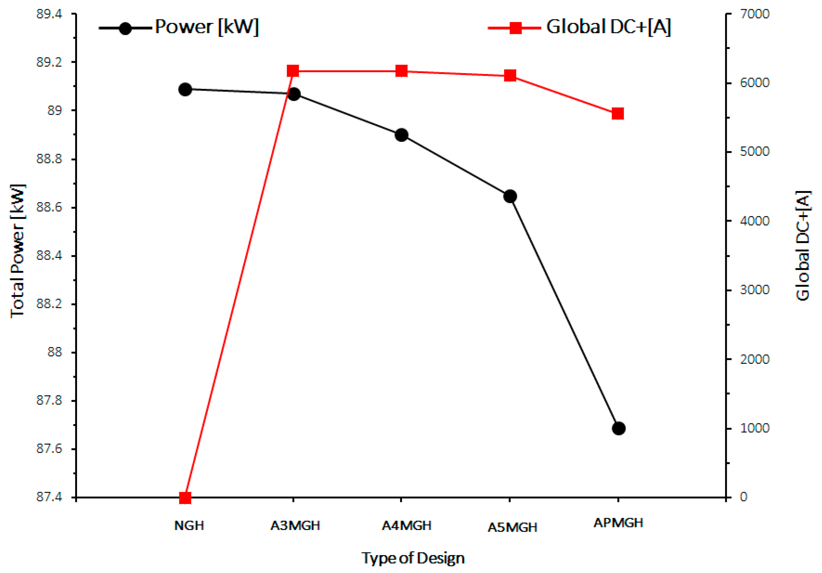
| NGH | A3MGH | A4MGH | A5MGH | APMGH | |
|---|---|---|---|---|---|
| Total Power [kW] | 89.09 | 89.07 | 88.90 | 88.65 | 87.69 |
| Global DC+[A] | 0 | 6176.81 | 6170.72 | 6104.15 | 5556.09 |
Publisher’s Note: MDPI stays neutral with regard to jurisdictional claims in published maps and institutional affiliations. |
© 2021 by the authors. Licensee MDPI, Basel, Switzerland. This article is an open access article distributed under the terms and conditions of the Creative Commons Attribution (CC BY) license (https://creativecommons.org/licenses/by/4.0/).
Share and Cite
Jeon, H.J.; Park, H.; Alhammadi, S.; Jung, J.H.; Kim, W.K. Optimal Magnetic Graphite Heater Design for Impurity Control in Single-Crystal Si Grower Using Crystal Growth Simulation. Processes 2022, 10, 70. https://doi.org/10.3390/pr10010070
Jeon HJ, Park H, Alhammadi S, Jung JH, Kim WK. Optimal Magnetic Graphite Heater Design for Impurity Control in Single-Crystal Si Grower Using Crystal Growth Simulation. Processes. 2022; 10(1):70. https://doi.org/10.3390/pr10010070
Chicago/Turabian StyleJeon, Hye Jun, Hyeonwook Park, Salh Alhammadi, Jae Hak Jung, and Woo Kyoung Kim. 2022. "Optimal Magnetic Graphite Heater Design for Impurity Control in Single-Crystal Si Grower Using Crystal Growth Simulation" Processes 10, no. 1: 70. https://doi.org/10.3390/pr10010070
APA StyleJeon, H. J., Park, H., Alhammadi, S., Jung, J. H., & Kim, W. K. (2022). Optimal Magnetic Graphite Heater Design for Impurity Control in Single-Crystal Si Grower Using Crystal Growth Simulation. Processes, 10(1), 70. https://doi.org/10.3390/pr10010070