
Analytical Techniques for the Characterization of Bioactive Coatings for Orthopaedic Implants


Abstract
1. Introduction
2. Interaction and Morphology Studies
2.1. Techniques for the Determination of the Chemical Composition of Coatings
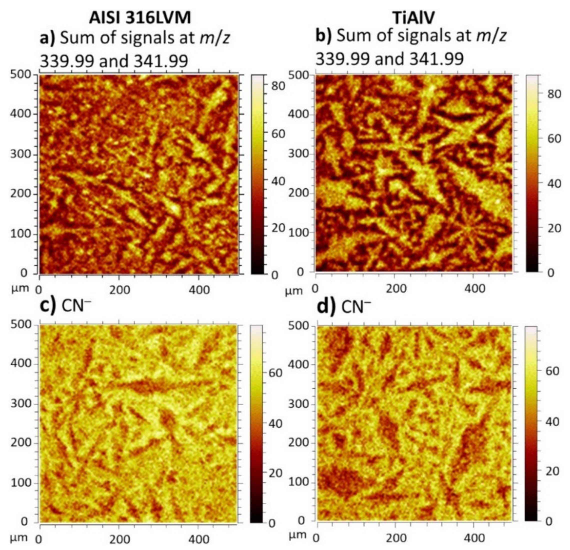
2.1.1. ToF-SIMS Analyses
2.1.2. XPS Analysis
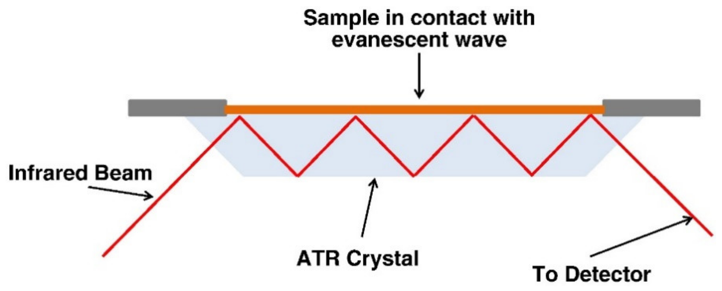
2.1.3. FTIR/ATR-FTIR
2.2. Techniques for the Determination of Morphology, Topography, and Internal Structure
2.2.1. AFM (At Nanoscale)/Profilometry (Larger Area)
2.2.2. SEM/EDX (SAXS)
2.2.3. TEM
2.2.4. 3D-Tomography
2.3. QCM
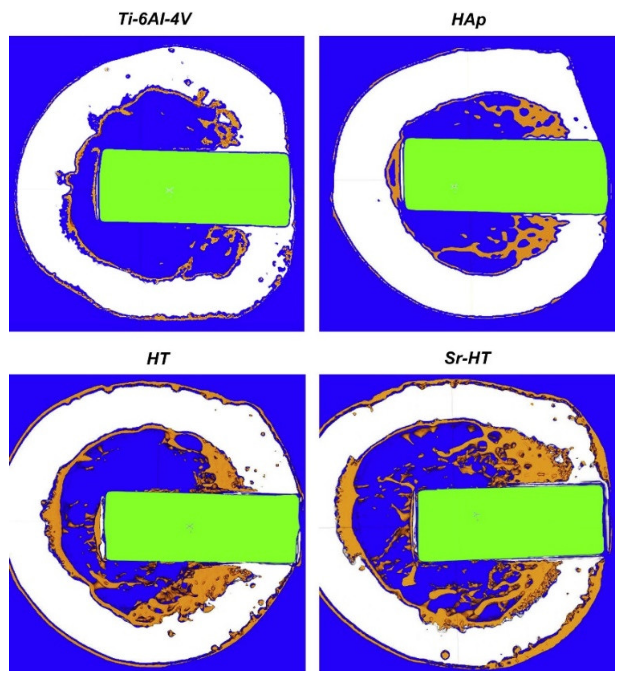
2.4. Coating Adhesion Measurements
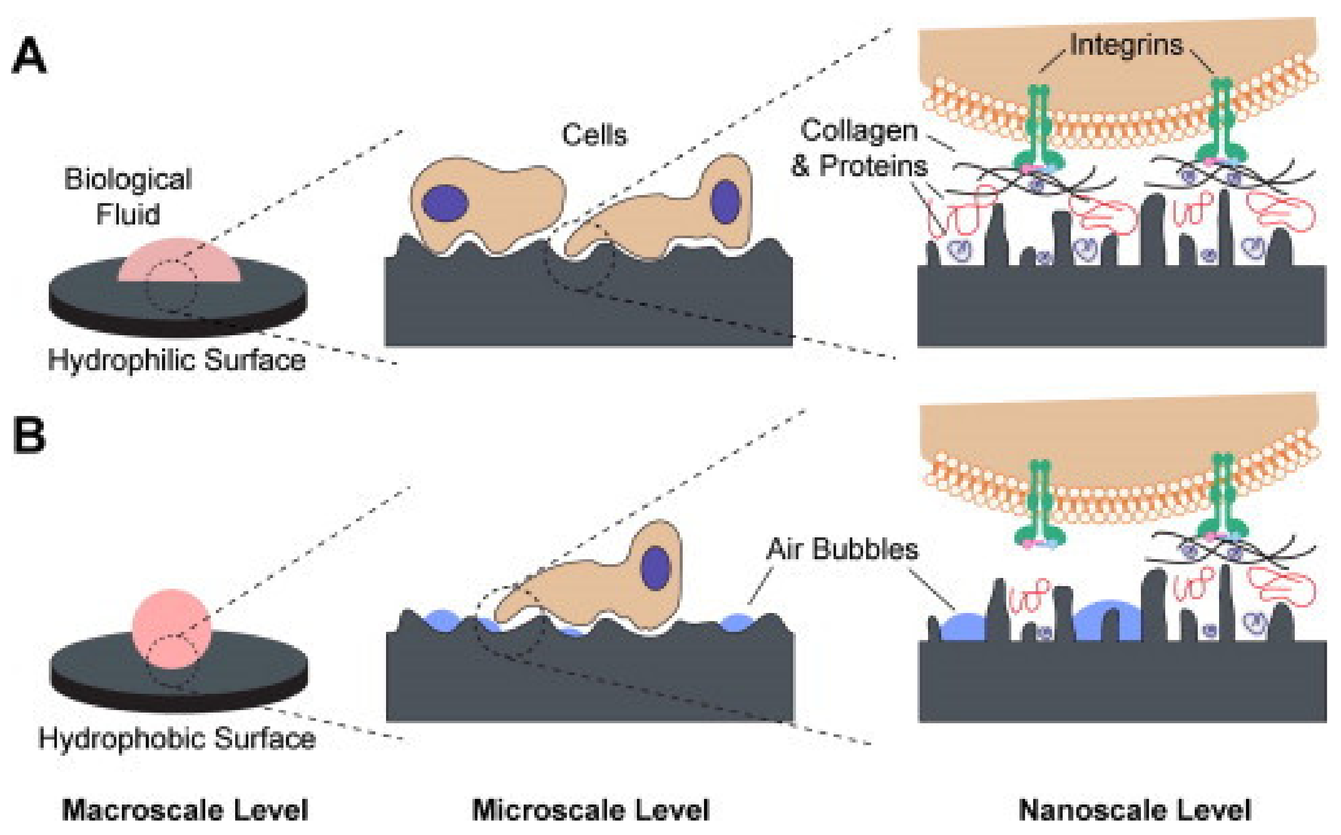
2.5. Contact Angle Measurements
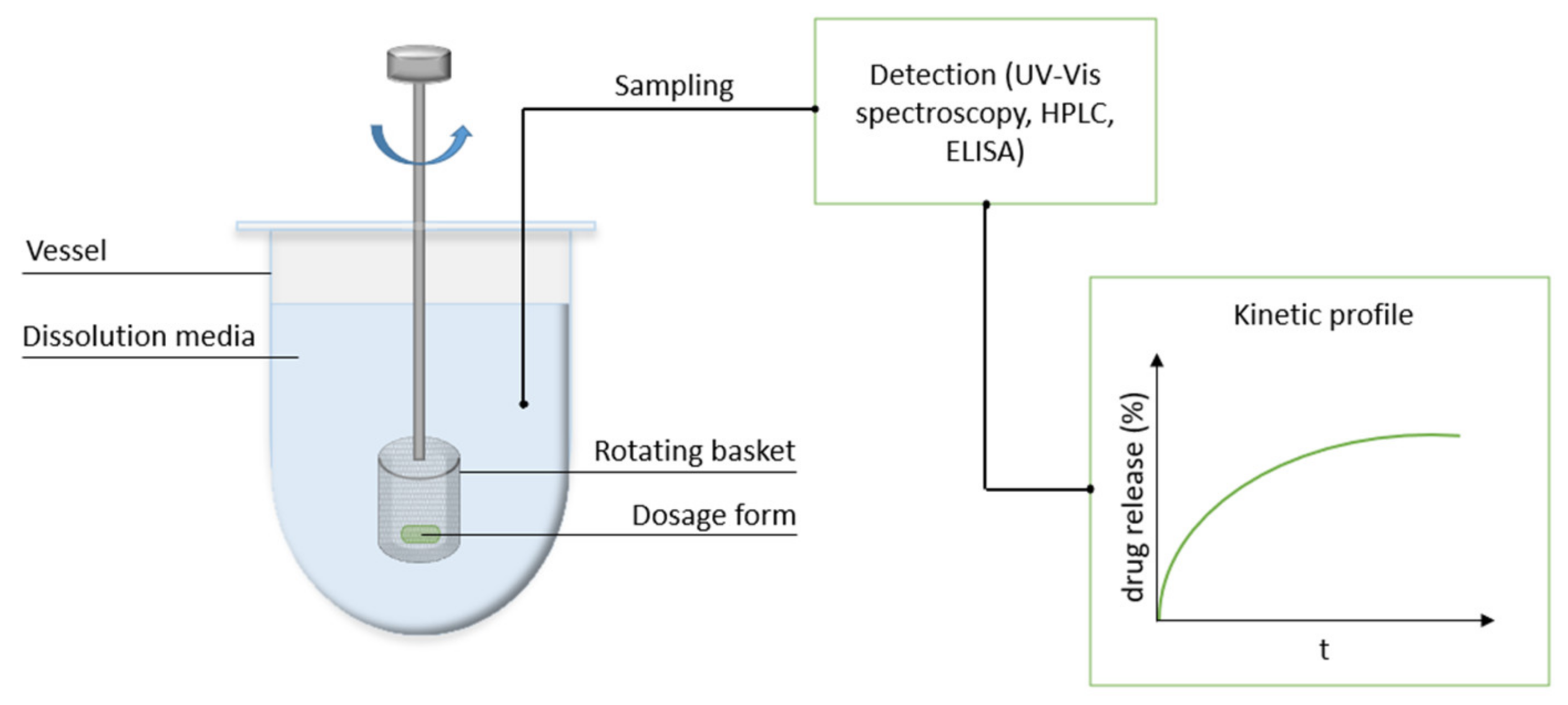
3. Controlled Release
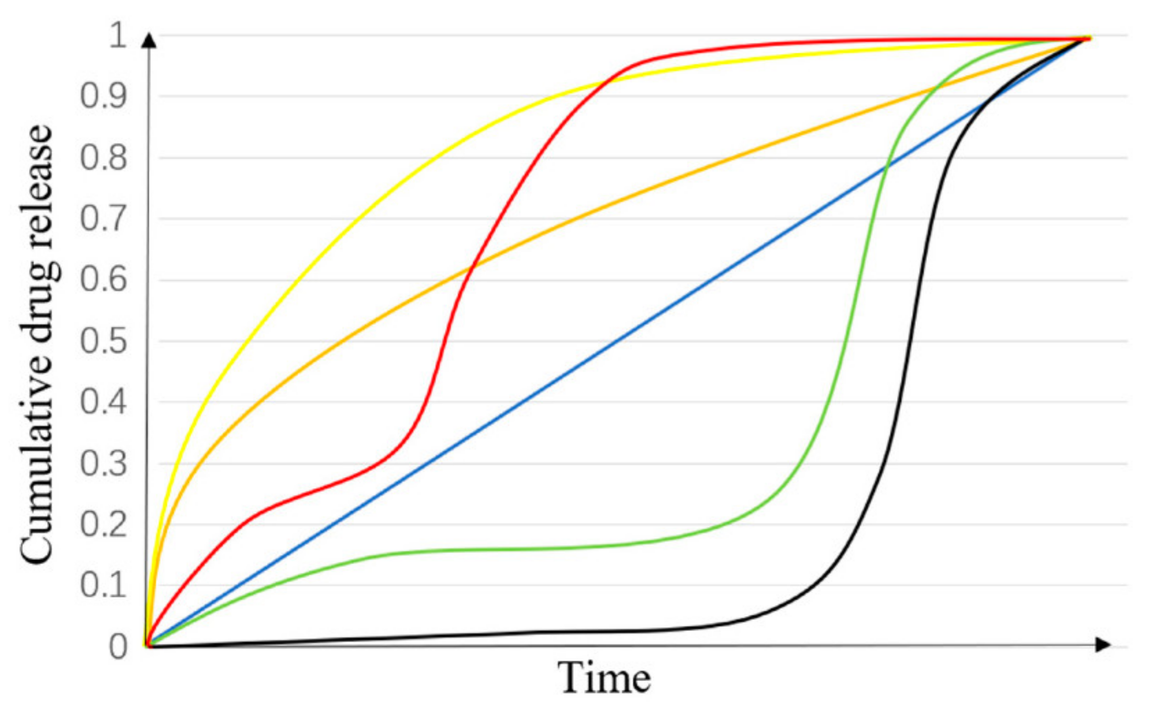
3.1. Release Models
3.2. Drug Release from Bioactive Coatings
4. Conclusions
Author Contributions
Funding
Institutional Review Board Statement
Informed Consent Statement
Data Availability Statement
Conflicts of Interest
Abbreviations
| AC | alternating current |
| AFM | atomic force microscopy |
| ANAB | accelerated neutral atom beam |
| ASTM | American Society for Testing and Materials |
| ATR-FTIR | attenuated total reflection Fourier transform infrared spectroscopy |
| BE | binding energy |
| BG | bioactive glass |
| CA | contact angle |
| CaP | calcium phosphate |
| CHI | chitosan |
| CMC | carboxymethyl cellulose |
| CT | computed tomography |
| DC | direct current |
| DCF | diclofenac |
| EDX/EDXS | energy dispersive X-ray spectroscopy |
| FTIR | Fourier transform infrared spectroscopy |
| FTT | Fast Fourier Transform |
| GCIB | gas cluster ion beam |
| GMA | glycidyl methacrylate |
| HA | Hydroxyapatite |
| HAADF | high-angle annular dark field |
| LbL | layer-by-layer |
| MAO | microarc oxidation |
| MCD | microcrystalline diamond |
| MH | microwave hydrothermal treatment |
| NCD | nanocrystalline diamond |
| NSAIDs | nonsteroidal anti-inflammatory drugs |
| nTiO2 | nano titania |
| PAA | poly(acrylic acid) |
| PCL | poly(ε-caprolactone) |
| PEEK | polyether ether ketone |
| PLGA | poly(lactic-co glycolic acid) |
| PLL | poly(l-lysine) |
| PVA | polyvinyl alcohol |
| QCM | quartz crystal microbalance |
| QCM-D | quartz crystal microbalance with dissipation monitoring |
| SAXS | small-angle X-ray scattering |
| SBF | simulated body fluids |
| SEM | scanning electron microscopy |
| Sr-HT | strontium-substituted hardystonite |
| STM | scanning tunnelling microscopy |
| TEM | transmission electron microscopy |
| TEOS–MTES | tetraethylorthosilicate–methyltriethoxysilane |
| TNTs | titania nanotubes |
| ToF-SIMS | time-on-flight secondary ion mass spectrometry |
| USP | United States Pharmacopeia |
| XPS | X-ray photoelectron spectroscopy |
| β-CD | beta cyclodextrin |
References
- Zhang, B.G.X.; Myers, D.E.; Wallace, G.G.; Brandt, M.; Choong, P.F.M. Bioactive Coatings for Orthopaedic Implants—Recent Trends in Development of Implant Coatings. Int. J. Mol. Sci. 2014, 15, 11878–11921. [Google Scholar] [CrossRef]
- Saini, M.; Singh, Y.; Arora, P.; Arora, V.; Jain, K. Implant biomaterials: A comprehensive review. World J. Clin. Cases WJCC 2015, 3, 52. [Google Scholar] [CrossRef] [PubMed]
- Mitra, I.; Bose, S.; Dernell, W.S.; Dasgupta, N.; Eckstrand, C.; Herrick, J.; Yaszemski, M.J.; Goodman, S.B.; Bandyopadhyay, A. 3D Printing in alloy design to improve biocompatibility in metallic implants. Mater. Today 2021, 45, 20–34. [Google Scholar] [CrossRef] [PubMed]
- Albrektsson, T.; Johansson, C. Osteoinduction, osteoconduction and osseointegration. Eur. Spine J. 2001, 10, S96–S101. [Google Scholar]
- Geng, Z.; Li, Z.; Cui, Z.; Wang, J.; Yang, X.; Liu, C. Novel Bionic Topography with MiR-21 Coating for Improving Bone-Implant Integration through Regulating Cell Adhesion and Angiogenesis. Nano Lett. 2020, 20, 7716–7721. [Google Scholar] [CrossRef]
- Rosales-Leal, J.I.; Rodriguez-Valverde, M.A.; Mazzaglia, G.; Ramón-Torregrosa, P.J.; Díaz-Rodríguez, L.; García-Martínez, O.; Vallecillo-Capilla, M.; Ruiz, C.; Cabrerizo-Vílchez, M.A. Effect of roughness, wettability and morphology of engineered titanium surfaces on osteoblast-like cell adhesion. Colloids Surf. A Physicochem. Eng. Asp. 2010, 365, 222–229. [Google Scholar] [CrossRef]
- Kulangara, K.; Leong, K.W. Substrate topography shapes cell function. Soft Matter 2009, 5, 4072–4076. [Google Scholar] [CrossRef]
- Chen, Y.; Xu, Z.; Smith, C.; Sankar, J. Recent advances on the development of magnesium alloys for biodegradable implants. Acta Biomater. 2014, 10, 4561–4573. [Google Scholar] [CrossRef] [PubMed]
- Perez, L.M.; Lalueza, P.; Monzon, M.; Puertolas, J.A.; Arruebo, M.; Santamaría, J. Hollow porous implants filled with mesoporous silica particles as a two-stage antibiotic-eluting device. Int. J. Pharm. 2011, 409, 1–8. [Google Scholar] [CrossRef]
- Prefac, G.-A.; Milea, M.-L.; Vadureanu, A.-M.; Muraru, S.; Dobrin, D.-I.; Isopencu, G.-O.; Jinga, S.-I.; Raileanu, M.; Bacalum, M.; Busuioc, C. CeO2 Containing Thin Films as Bioactive Coatings for Orthopaedic Implants. Coatings 2020, 10, 642. [Google Scholar] [CrossRef]
- Mehnath, S.; Arjama, M.; Rajan, M.; Premkumar, K.; Karthikeyan, K.; Jeyaraj, M. Mineralization of bioactive marine sponge and electrophoretic deposition on Ti-6Al-4V implant for osteointegration. Surf. Coat. Technol. 2020, 392, 125727. [Google Scholar] [CrossRef]
- Nuswantoro, N.F.; Juliadmi, D.; Fajri, H.; Manjas, M.; Suharti, N.; Tjong, D.H.; Affi, J. Electrophoretic Deposition Performance of Hydroxyapatite Coating on Titanium Alloys for Orthopedic Implant Application. In Proceedings of the Materials Science Forum; Trans Tech Publications: Stafa-Zurich, Switzerland, 2020; pp. 69–81. [Google Scholar]
- Nichol, T.; Callaghan, J.; Townsend, R.; Stockley, I.; Hatton, P.V.; Le Maitre, C.; Smith, T.J.; Akid, R. The antimicrobial activity and biocompatibility of a controlled gentamicin-releasing single-layer sol-gel coating on hydroxyapatite-coated titanium. Bone Jt. J. 2021, 103, 522–529. [Google Scholar] [CrossRef]
- Ansari, Z.; Kalantar, M.; Kharaziha, M.; Ambrosio, L.; Raucci, M.G. Polycaprolactone/fluoride substituted-hydroxyapatite (PCL/FHA) nanocomposite coatings prepared by in-situ sol-gel process for dental implant applications. Prog. Org. Coat. 2020, 147, 105873. [Google Scholar] [CrossRef]
- Escobar, A.; Muzzio, N.; Moya, S.E. Antibacterial Layer-by-Layer Coatings for Medical Implants. Pharmaceutics 2021, 13, 16. [Google Scholar] [CrossRef]
- Gulati, K.; Ramakrishnan, S.; Aw, M.S.; Atkins, G.J.; Findlay, D.M.; Losic, D. Biocompatible polymer coating of titania nanotube arrays for improved drug elution and osteoblast adhesion. Acta Biomater. 2012, 8, 449–456. [Google Scholar] [CrossRef] [PubMed]
- Ordikhani, F.; Zustiak, S.P.; Simchi, A. Surface Modifications of Titanium Implants by Multilayer Bioactive Coatings with Drug Delivery Potential: Antimicrobial, Biological, and Drug Release Studies. JOM 2016, 68, 1100–1108. [Google Scholar] [CrossRef]
- Ballarre, J.; Aydemir, T.; Liverani, L.; Roether, J.A.; Goldmann, W.; Boccaccini, A.R. Versatile bioactive and antibacterial coating system based on silica, gentamicin, and chitosan: Improving early stage performance of titanium implants. Surf. Coat. Technol. 2020, 381, 125138. [Google Scholar] [CrossRef]
- Kaur, G.; Kumar, V.; Baino, F.; Mauro, J.C.; Pickrell, G.; Evans, I.; Bretcanu, O. Mechanical properties of bioactive glasses, ceramics, glass-ceramics and composites: State-of-the-art review and future challenges. Mater. Sci. Eng. C 2019, 104, 109895. [Google Scholar] [CrossRef]
- Zarghami, V.; Ghorbani, M.; Bagheri, K.P.; Shokrgozar, M.A. Prevention the formation of biofilm on orthopedic implants by melittin thin layer on chitosan/bioactive glass/vancomycin coatings. J. Mater. Sci. Mater. Med. 2021, 32, 75. [Google Scholar] [CrossRef] [PubMed]
- Harb, S.V.; Bassous, N.J.; de Souza, T.A.; Trentin, A.; Pulcinelli, S.H.; Santilli, C.V.; Webster, T.J.; Lobo, A.O.; Hammer, P. Hydroxyapatite and β-TCP modified PMMA-TiO2 and PMMA-ZrO2 coatings for bioactive corrosion protection of Ti6Al4V implants. Mater. Sci. Eng. C 2020, 116, 111149. [Google Scholar] [CrossRef]
- Yao, Q.; Jiang, Y.; Tan, S.; Fu, X.; Li, B.; Liu, L. Composition and bioactivity of calcium phosphate coatings on anodic oxide nanotubes formed on pure Ti and Ti-6Al-4V alloy substrates. Mater. Sci. Eng. C 2020, 110, 110687. [Google Scholar] [CrossRef]
- Bhong, S.Y.; More, N.; Choppadandi, M.; Kapusetti, G. Review on carbon nanomaterials as typical candidates for orthopaedic coatings. SN Appl. Sci. 2019, 1, 76. [Google Scholar] [CrossRef]
- Maver, U.; Xhanari, K.; Žižek, M.; Gradišnik, L.; Repnik, K.; Potočnik, U.; Finšgar, M. Carboxymethyl cellulose/diclofenac bioactive coatings on AISI 316LVM for controlled drug delivery, and improved osteogenic potential. Carbohydr. Polym. 2020, 230, 115612. [Google Scholar] [CrossRef] [PubMed]
- Li, Y.; Yang, Y.; Li, R.; Tang, X.; Guo, D.; Qing, Y.; Qin, Y. Enhanced antibacterial properties of orthopedic implants by titanium nanotube surface modification: A review of current techniques. Int. J. Nanomed. 2019, 14, 7217. [Google Scholar] [CrossRef]
- Xiao, W.; Fu, H.; Rahaman, M.N.; Liu, Y.; Bal, B.S. Hollow hydroxyapatite microspheres: A novel bioactive and osteoconductive carrier for controlled release of bone morphogenetic protein-2 in bone regeneration. Acta Biomater. 2013, 9, 8374–8383. [Google Scholar] [CrossRef]
- Zhang, J.; Li, J.; Jia, G.; Jiang, Y.; Liu, Q.; Yang, X.; Pan, S. Improving osteogenesis of PLGA/HA porous scaffolds based on dual delivery of BMP-2 and IGF-1 via a polydopamine coating. RSC Adv. 2017, 7, 56732–56742. [Google Scholar] [CrossRef]
- Gan, Q.; Zhu, J.; Yuan, Y.; Liu, H.; Qian, J.; Li, Y.; Liu, C. A dual-delivery system of pH-responsive chitosan-functionalized mesoporous silica nanoparticles bearing BMP-2 and dexamethasone for enhanced bone regeneration. J. Mater. Chem. B 2015, 3, 2056–2066. [Google Scholar] [CrossRef] [PubMed]
- Peter, B.; Pioletti, D.P.; Laïb, S.; Bujoli, B.; Pilet, P.; Janvier, P.; Guicheux, J.; Zambelli, P.Y.; Bouler, J.M.; Gauthier, O. Calcium phosphate drug delivery system: Influence of local zoledronate release on bone implant osteointegration. Bone 2005, 36, 52–60. [Google Scholar] [CrossRef]
- Wan, P.; Wang, W.; Zheng, L.; Qin, L.; Yang, K. One-step electrodeposition synthesis of bisphosphonate loaded magnesium implant: A strategy to modulate drug release for osteoporotic fracture healing. J. Mater. Sci. Technol. 2021, 78, 92–99. [Google Scholar] [CrossRef]
- Pan, C.-J.; Pang, L.-Q.; Gao, F.; Wang, Y.-N.; Liu, T.; Ye, W.; Hou, Y.-H. Anticoagulation and endothelial cell behaviors of heparin-loaded graphene oxide coating on titanium surface. Mater. Sci. Eng. C 2016, 63, 333–340. [Google Scholar] [CrossRef]
- Maver, T.; Mastnak, T.; Mihelič, M.; Maver, U.; Finšgar, M. Clindamycin-Based 3D-Printed and Electrospun Coatings for Treatment of Implant-Related Infections. Materials 2021, 14, 1464. [Google Scholar] [CrossRef]
- Yusoff, M.F.M.; Kadir, M.R.A.; Iqbal, N.; Hassan, M.A.; Hussain, R. Dipcoating of poly (ε-caprolactone)/hydroxyapatite composite coating on Ti6Al4V for enhanced corrosion protection. Surf. Coat. Technol. 2014, 245, 102–107. [Google Scholar] [CrossRef]
- Mishra, S.K.; Kannan, S. Development, mechanical evaluation and surface characteristics of chitosan/polyvinyl alcohol based polymer composite coatings on titanium metal. J. Mech. Behav. Biomed. Mater. 2014, 40, 314–324. [Google Scholar] [CrossRef] [PubMed]
- Omar, S.A.; Ballarre, J.; Castro, Y.; Martinez Campos, E.; Schreiner, W.; Durán, A.; Cere, S.M. 58S and 68S sol-gel glass-like bioactive coatings for enhancing the implant performance of AZ91D magnesium alloy. Surf. Coat. Technol. 2020, 400, 126224. [Google Scholar] [CrossRef]
- Stigter, M.; de Groot, K.; Layrolle, P. Incorporation of tobramycin into biomimetic hydroxyapatite coating on titanium. Biomaterials 2002, 23, 4143–4153. [Google Scholar] [CrossRef]
- Wang, T.; Weng, Z.; Liu, X.; Yeung, K.W.; Pan, H.; Wu, S. Controlled release and biocompatibility of polymer/titania nanotube array system on titanium implants. Bioact. Mater. 2017, 2, 44–50. [Google Scholar] [CrossRef]
- Kamaly, N.; Yameen, B.; Wu, J.; Farokhzad, O.C. Degradable Controlled-Release Polymers and Polymeric Nanoparticles: Mechanisms of Controlling Drug Release. Chem. Rev. 2016, 116, 2602–2663. [Google Scholar] [CrossRef] [PubMed]
- Aydemir, T.; Liverani, L.; Pastore, J.I.; Ceré, S.M.; Goldmann, W.H.; Boccaccini, A.R.; Ballarre, J. Functional behavior of chitosan/gelatin/silica-gentamicin coatings by electrophoretic deposition on surgical grade stainless steel. Mater. Sci. Eng. C 2020, 115, 111062. [Google Scholar] [CrossRef]
- Pan, H.; Han, J.J.; Park, Y.-D.; Cho, T.H.; Hwang, S.J. Effect of sustained release of rhBMP-2 from dried and wet hyaluronic acid hydrogel carriers compared with direct dip coating of rhBMP-2 on peri-implant osteogenesis of dental implants in canine mandibles. J. Cranio-Maxillofac. Surg. 2016, 44, 116–125. [Google Scholar] [CrossRef] [PubMed]
- Pishbin, F.; Mouriño, V.; Flor, S.; Kreppel, S.; Salih, V.; Ryan, M.P.; Boccaccini, A.R. Electrophoretic Deposition of Gentamicin-Loaded Bioactive Glass/Chitosan Composite Coatings for Orthopaedic Implants. ACS Appl. Mater. Interfaces 2014, 6, 8796–8806. [Google Scholar] [CrossRef]
- Kim, H.W.; Knowles, J.C.; Kim, H.E. Porous scaffolds of gelatin–hydroxyapatite nanocomposites obtained by biomimetic ap-proach: Characterization and antibiotic drug release. J. Biomed. Mater. Res. Part B Appl. Biomater. 2005, 74, 686–698. [Google Scholar] [CrossRef]
- Graham, D.J.; Wagner, M.S.; Castner, D.G. Information from complexity: Challenges of TOF-SIMS data interpretation. Appl. Surf. Sci. 2006, 252, 6860–6868. [Google Scholar] [CrossRef]
- Hofmann, S. Quantitative depth profiling in surface analysis: A review. Surf. Interface Anal. 1980, 2, 148–160. [Google Scholar] [CrossRef]
- Wirtz, T.; Philipp, P.; Audinot, J.N.; Dowsett, D.; Eswara, S. High-resolution high-sensitivity elemental imaging by secondary ion mass spectrometry: From traditional 2D and 3D imaging to correlative microscopy. Nanotechnology 2015, 26, 434001. [Google Scholar] [CrossRef] [PubMed]
- Seah, M.P. A review of the analysis of surfaces and thin films by AES and XPS. Vacuum 1984, 34, 463–478. [Google Scholar] [CrossRef]
- Seah, M. The quantitative analysis of surfaces by XPS: A review. Surf. Interface Anal. 1980, 2, 222–239. [Google Scholar] [CrossRef]
- Valand, R.; Tanna, S.; Lawson, G.; Bengtström, L. A review of Fourier Transform Infrared (FTIR) spectroscopy used in food adulteration and authenticity investigations. Food Addit. Contam. Part A 2020, 37, 19–38. [Google Scholar] [CrossRef] [PubMed]
- Smith, J.; Larson, C.; Campbell, S. Recent applications of SEM and AFM for assessing topography of metal and related coatings—A review. Trans. IMF 2011, 89, 18–27. [Google Scholar] [CrossRef]
- Dong, Z.L.; Khor, K.A.; Quek, C.; White, T.J.; Cheang, P. TEM and STEM analysis on heat-treated and in vitro plasma-sprayed hydroxyapatite/Ti-6Al-4V composite coatings. Biomaterials 2003, 24, 97–105. [Google Scholar] [CrossRef]
- Seong, H.; Choi, S.; Matusik, K.E.; Kastengren, A.L.; Powell, C.F. 3D pore analysis of gasoline particulate filters using X-ray tomography: Impact of coating and ash loading. J. Mater. Sci. 2019, 54, 6053–6065. [Google Scholar] [CrossRef]
- Alassi, A.; Benammar, M.; Brett, D. Quartz Crystal Microbalance Electronic Interfacing Systems: A Review. Sensors 2017, 17, 2799. [Google Scholar] [CrossRef]
- Chalker, P.R.; Bull, S.J.; Rickerby, D.S. A review of the methods for the evaluation of coating-substrate adhesion. Mater. Sci. Eng. A 1991, 140, 583–592. [Google Scholar] [CrossRef]
- Eral, H.; Oh, J. Contact angle hysteresis: A review of fundamentals and applications. Colloid Polym. Sci. 2013, 291, 247–260. [Google Scholar] [CrossRef]
- Liu, F.; Gu, Y.; Shen, X.; Ferdous, S.; Wang, H.-W.; Russell, T.P. Characterization of the morphology of solution-processed bulk heterojunction organic photovoltaics. Prog. Polym. Sci. 2013, 38, 1990–2052. [Google Scholar] [CrossRef]
- Guo, Q. Polymer Morphology: Principles, Characterization, and Processing; John Wiley & Sons: Hoboken, NJ, USA, 2016. [Google Scholar]
- Finšgar, M.; Kovač, J.; Maver, U. The development and characterization of bioactive coatings for local drug delivery in orthopedic applications. Prog. Org. Coat. 2021, 158, 106350. [Google Scholar] [CrossRef]
- Finšgar, M. Advanced surface analysis using GCIB-C60++-tandem-ToF-SIMS and GCIB-XPS of 2-mercaptobenzimidazole corrosion inhibitor on brass. Microchem. J. 2020, 159, 105495. [Google Scholar] [CrossRef]
- Winograd, N. Gas Cluster Ion Beams for Secondary Ion Mass Spectrometry. Annu. Rev. Anal. Chem. 2018, 11, 29–48. [Google Scholar] [CrossRef] [PubMed]
- Michiardi, A.; Hélary, G.; Nguyen, P.-C.T.; Gamble, L.J.; Anagnostou, F.; Castner, D.G.; Migonney, V. Bioactive polymer grafting onto titanium alloy surfaces. Acta Biomater. 2010, 6, 667–675. [Google Scholar] [CrossRef]
- Acheson, J.; McKillop, S.; Lemoine, P.; Boyd, A.; Meenan, B. Control of magnesium alloy corrosion by bioactive calcium phosphate coating: Implications for resorbable orthopaedic implants. Materialia 2019, 6, 100291. [Google Scholar] [CrossRef]
- Zanna, S.; Saulou, C.; Mercier-Bonin, M.; Despax, B.; Raynaud, P.; Seyeux, A.; Marcus, P. Ageing of plasma-mediated coatings with embedded silver nanoparticles on stainless steel: An XPS and ToF-SIMS investigation. Appl. Surf. Sci. 2010, 256, 6499–6505. [Google Scholar] [CrossRef]
- Ratner, B.D.; McElroy, B.J. Electron Spectroscopy for Chemical Analysis: Applications in the Biomedical Sciences. In Spectroscopy in the Biomedical Sciences; John Wiley & Sons: West Sussex, UK, 2018; pp. 107–140. [Google Scholar]
- Cumpson, P.J.; Portoles, J.F.; Barlow, A.J.; Sano, N.; Birch, M. Depth profiling organic/inorganic interfaces by argon gas cluster ion beams: Sputter yield data for biomaterials, in-vitro diagnostic and implant applications. Surf. Interface Anal. 2013, 45, 1859–1868. [Google Scholar] [CrossRef]
- Sano, N.; Barlow, A.J.; Tsakonas, C.; Cranton, W.; Cumpson, P.J. Optimal conditions for gas cluster ion beams in studying inorganic interface species: Improved chemical information at a ZnO interface. Surf. Interface Anal. 2016, 48, 575–579. [Google Scholar] [CrossRef]
- Vokoun, D.; Racek, J.; Kadeřávek, L.; Kei, C.C.; Yu, Y.S.; Klimša, L.; Šittner, P. Atomic Layer-Deposited TiO2 Coatings on NiTi Surface. J. Mater. Eng. Perform. 2018, 27, 572–579. [Google Scholar] [CrossRef]
- Pei, X.; Zeng, Y.; He, R.; Li, Z.; Tian, L.; Wang, J.; Wan, Q.; Li, X.; Bao, H. Single-walled carbon nanotubes/hydroxyapatite coatings on titanium obtained by electrochemical deposition. Appl. Surf. Sci. 2014, 295, 71–80. [Google Scholar] [CrossRef]
- Ballarre, J.; Manjubala, I.; Schreiner, W.H.; Orellano, J.C.; Fratzl, P.; Ceré, S. Improving the osteointegration and bone–implant interface by incorporation of bioactive particles in sol–gel coatings of stainless steel implants. Acta Biomater. 2010, 6, 1601–1609. [Google Scholar] [CrossRef] [PubMed]
- De Santis, S.; Sotgiu, G.; Porcelli, F.; Marsotto, M.; Iucci, G.; Orsini, M. A Simple Cerium Coating Strategy for Titanium Oxide Nano-tubes’ Bioactivity Enhancement. Nanomaterials 2021, 11, 445. [Google Scholar] [CrossRef]
- Lai, M.; Cai, K.; Zhao, L.; Chen, X.; Hou, Y.; Yang, Z. Surface Functionalization of TiO2 Nanotubes with Bone Morphogenetic Protein 2 and Its Synergistic Effect on the Differentiation of Mesenchymal Stem Cells. Biomacromolecules 2011, 12, 1097–1105. [Google Scholar] [CrossRef]
- Youn, Y.H.; Lee, S.J.; Choi, G.R.; Lee, H.R.; Lee, D.; Heo, D.N.; Kim, B.-S.; Bang, J.B.; Hwang, Y.-S.; Correlo, V.M. Simple and facile preparation of recombinant human bone morphogenetic protein-2 immobilized titanium implant via initiated chemical vapor deposition technique to promote osteogenesis for bone tissue engineering application. Mater. Sci. Eng. C 2019, 100, 949–958. [Google Scholar] [CrossRef] [PubMed]
- Hong, W.; Guo, F.; Chen, J.; Wang, X.; Zhao, X.; Xiao, P. Bioactive glass–chitosan composite coatings on PEEK: Effects of surface wettability and roughness on the interfacial fracture resistance and in vitro cell response. Appl. Surf. Sci. 2018, 440, 514–523. [Google Scholar] [CrossRef]
- Asmatulu, R.; Khan, W.S. (Eds.) Chapter 13—Characterization of electrospun nanofibers. In Synthesis and Applications of Electrospun Nanofibers; Elsevier: Amsterdam, The Netherlands, 2019; pp. 257–281. [Google Scholar]
- Titus, D.; Samuel, E.J.J.; Roopan, S.M. Nanoparticle characterization techniques. In Green Synthesis, Characterization and Applications of Nanoparticles; Elsevier: Amsterdam, The Netherlands, 2019; pp. 303–319. [Google Scholar]
- Berthomieu, C.; Hienerwadel, R. Fourier transform infrared (FTIR) spectroscopy. Photosynth. Res. 2009, 101, 157–170. [Google Scholar] [CrossRef]
- Song, K. 4—Interphase characterization in rubber nanocomposites. In Progress in Rubber Nanocomposites; Thomas, S., Maria, H.J., Eds.; Woodhead Publishing: Duxford, UK, 2017; pp. 115–152. [Google Scholar]
- Skoog, D.A.; Holler, F.J.; Crouch, S.R. Principles of Instrumental Analysis; Cengage Learning: Boston, MA, USA, 2017. [Google Scholar]
- Kowalczuk, D.; Pitucha, M. Application of FTIR Method for the Assessment of Immobilization of Active Substances in the Matrix of Biomedical Materials. Materials 2019, 12, 2972. [Google Scholar] [CrossRef] [PubMed]
- FT-IR Spectroscopy Attenuated Total Reflectance (ATR) (PDF). Available online: https://cmdis.rpi.edu/sites/default/files/ATR_FTIR.pdf (accessed on 2 November 2021).
- Margenot, A.J.; Calderón, F.J.; Goyne, K.W.; Mukome, F.N.D.; Parikh, S.J. IR Spectroscopy, Soil Analysis Applications. In Encyclopedia of Spectroscopy and Spectrometry, 3rd ed.; Lindon, J.C., Tranter, G.E., Koppenaal, D.W., Eds.; Academic Press: Oxford, UK, 2017; pp. 448–454. [Google Scholar]
- Shai, Y. ATR-FTIR studies in pore forming and membrane induced fusion peptides. Biochim. Biophys. Acta 2013, 1828, 2306–2313. [Google Scholar] [CrossRef] [PubMed]
- Akhtar, M.A.; Mariotti, C.E.; Conti, B.; Boccaccini, A.R. Electrophoretic deposition of ferulic acid loaded bioactive glass/chitosan as antibacterial and bioactive composite coatings. Surf. Coat. Technol. 2021, 405, 126657. [Google Scholar] [CrossRef]
- Huang, Y.; Hao, M.; Nian, X.; Qiao, H.; Zhang, X.; Zhang, X.; Song, G.; Guo, J.; Pang, X.; Zhang, H. Strontium and copper co-substituted hydroxyapatite-based coatings with improved antibacterial activity and cytocompatibility fabricated by electrodeposition. Ceram. Int. 2016, 42, 11876–11888. [Google Scholar] [CrossRef]
- Likibi, F.; Jiang, B.; Li, B. Biomimetic nanocoating promotes osteoblast cell adhesion on biomedical implants. J. Mater. Res. 2008, 23, 3222–3228. [Google Scholar] [CrossRef][Green Version]
- Huang, P.; Wang, J.; Lai, S.; Liu, F.; Ni, N.; Cao, Q.; Liu, W.; Deng, D.Y.; Zhou, W. Surface modified titania nanotubes containing anti-bacterial drugs for controlled delivery nanosystems with high bioactivity. J. Mater. Chem. B 2014, 2, 8616–8625. [Google Scholar] [CrossRef]
- Khoshnood, N.; Zamanian, A.; Massoudi, A. Mussel-inspired surface modification of titania nanotubes as a novel drug delivery system. Mater. Sci. Eng. C 2017, 77, 748–754. [Google Scholar] [CrossRef] [PubMed]
- Kiran, A.S.K.; Kizhakeyil, A.; Ramalingam, R.; Verma, N.K.; Lakshminarayanan, R.; Kumar, T.S.; Doble, M.; Ramakrishna, S. Drug loaded electrospun polymer/ceramic composite nanofibrous coatings on titanium for implant related infections. Ceram. Int. 2019, 45, 18710–18720. [Google Scholar] [CrossRef]
- Li, X.; Zhitomirsky, I. Deposition of poly(methyl methacrylate) and composites containing bioceramics and bioglass by dip coating using isopropanol-water co-solvent. Prog. Org. Coat. 2020, 148, 105883. [Google Scholar] [CrossRef]
- Zhao, P.; Liu, H.; Deng, H.; Xiao, L.; Qin, C.; Du, Y.; Shi, X. A study of chitosan hydrogel with embedded mesoporous silica nanoparticles loaded by ibuprofen as a dual stimuli-responsive drug release system for surface coating of titanium implants. Colloids Surf. B Biointerfaces 2014, 123, 657–663. [Google Scholar] [CrossRef] [PubMed]
- Rožanc, J.; Žižek, M.; Milojević, M.; Maver, U.; Finšgar, M. Dexamethasone-Loaded Bioactive Coatings on Medical Grade Stainless Steel Promote Osteointegration. Pharmaceutics 2021, 13, 568. [Google Scholar] [CrossRef]
- Horvat, G.; Xhanari, K.; Finšgar, M.; Gradišnik, L.; Maver, U.; Knez, Ž.; Novak, Z. Novel ethanol-induced pectin–xanthan aerogel coatings for orthopedic applications. Carbohydr. Polym. 2017, 166, 365–376. [Google Scholar] [CrossRef] [PubMed]
- Jahanmard, F.; Croes, M.; Castilho, M.; Majed, A.; Steenbergen, M.; Lietaert, K.; Vogely, H.; van der Wal, B.; Stapels, D.; Malda, J. Bactericidal coating to prevent early and delayed implant-related infections. J. Control. Release 2020, 326, 38–52. [Google Scholar] [CrossRef] [PubMed]
- Finšgar, M.; Uzunalić, A.P.; Stergar, J.; Gradišnik, L.; Maver, U. Novel chitosan/diclofenac coatings on medical grade stainless steel for hip replacement applications. Sci. Rep. 2016, 6, 26653. [Google Scholar] [CrossRef] [PubMed]
- Rezk, A.I.; Mousa, H.M.; Lee, J.; Park, C.H.; Kim, C.S. Composite PCL/HA/simvastatin electrospun nanofiber coating on biodegradable Mg alloy for orthopedic implant application. J. Coat. Technol. Res. 2019, 16, 477–489. [Google Scholar] [CrossRef]
- Hashemi, A.; Ezati, M.; Mohammadnejad, J.; Houshmand, B.; Faghihi, S. Chitosan Coating of TiO2 Nanotube Arrays for Improved Metformin Release and Osteoblast Differentiation. Int. J. Nanomed. 2020, 15, 4471–4481. [Google Scholar] [CrossRef] [PubMed]
- Cordero-Arias, L.; Cabanas-Polo, S.; Goudouri, O.M.; Misra, S.K.; Gilabert, J.; Valsami-Jones, E.; Sanchez, E.; Virtanen, S.; Boccaccini, A.R. Electrophoretic deposition of ZnO/alginate and ZnO-bioactive glass/alginate composite coatings for antimicrobial applications. Mater. Sci. Eng. C 2015, 55, 137–144. [Google Scholar] [CrossRef] [PubMed]
- Sasireka, A.; Rajendran, R.; Raj, V. In vitro corrosion resistance and cytocompatibility of minerals substituted apatite/biopolymers duplex coatings on anodized Ti for orthopedic implant applications. Arab. J. Chem. 2020, 13, 6312–6326. [Google Scholar] [CrossRef]
- Nandi, T.; Ainavarapu, S.R.K. Applications of atomic force microscopy in modern biology. Emerg. Top. Life Sci. 2021, 5, 103–111. [Google Scholar] [CrossRef]
- Zeller, A.; Musyanovych, A.; Kappl, M.; Ethirajan, A.; Dass, M.; Markova, D.; Klapper, M.; Landfester, K. Nanostructured Coatings by Adhesion of Phosphonated Polystyrene Particles onto Titanium Surface for Implant Material Applications. ACS Appl. Mater. Interfaces 2010, 2, 2421–2428. [Google Scholar] [CrossRef]
- Burnat, B.; Olejarz, P.; Batory, D.; Cichomski, M.; Kaminska, M.; Bociaga, D. Titanium Dioxide Coatings Doubly-Doped with Ca and Ag Ions as Corrosion Resistant, Biocompatible, and Bioactive Materials for Medical Applications. Coatings 2020, 10, 169. [Google Scholar] [CrossRef]
- Brammer, K.S.; Oh, S.; Cobb, C.J.; Bjursten, L.M.; van der Heyde, H.; Jin, S. Improved bone-forming functionality on diameter-controlled TiO2 nanotube surface. Acta Biomater. 2009, 5, 3215–3223. [Google Scholar] [CrossRef]
- Verza, B.S.; van den Beucken, J.J.; Brandt, J.V.; Junior, M.J.; Barão, V.A.; Piazza, R.D.; Tagit, O.; Spolidorio, D.M.; Vergani, C.E.; de Avila, E.D. A long-term controlled drug-delivery with anionic beta cyclodextrin complex in layer-by-layer coating for percutaneous implants devices. Carbohydr. Polym. 2021, 257, 117604. [Google Scholar] [CrossRef] [PubMed]
- Singh, A.K. (Ed.) Chapter 4—Experimental Methodologies for the Characterization of Nanoparticles. In Engineered Nanoparticles; Academic Press: Boston, MA, USA, 2016; pp. 125–170. [Google Scholar]
- Van de Ven, A.L.; Mack, A.; Dunner, K.; Ferrari, M.; Serda, R.E. Chapter one—Preparation, Characterization, and Cellular Associations of Silicon Logic-Embedded Vectors. In Methods in Enzymology; Düzgüneş, N., Ed.; Academic Press: San Diego, CA, USA, 2012; Volume 508, pp. 1–16. [Google Scholar]
- Mohammed, A.; Abdullah, A. Scanning electron microscopy (SEM): A review. In Proceedings of the 2018 International Conference on Hydraulics and Pneumatics—HERVEX, Băile Govora, Romania, 7–9 November 2018; pp. 7–9. [Google Scholar]
- Tao, B.; Zhao, W.; Lin, C.; Yuan, Z.; He, Y.; Lu, L.; Chen, M.; Ding, Y.; Yang, Y.; Xia, Z. Surface modification of titanium implants by ZIF-8@ Levo/LBL coating for inhibition of bacterial-associated infection and enhancement of in vivo osseointegration. Chem. Eng. J. 2020, 390, 124621. [Google Scholar] [CrossRef]
- Xia, K.; Pan, H.; Wang, T.; Ma, S.; Niu, J.; Xiang, Z.; Song, Y.; Yang, H.; Tang, X.; Lu, W. Effect of Ca/P ratio on the structural and corrosion properties of biomimetic Ca/P coatings on ZK60 magnesium alloy. Mater. Sci. Eng. C 2017, 72, 676–681. [Google Scholar] [CrossRef] [PubMed]
- Wei, Y.; Liu, Z.; Zhu, X.; Jiang, L.; Shi, W.; Wang, Y.; Xu, N.; Gang, F.; Wang, X.; Zhao, L. Dual directions to address the problem of aseptic loosening via electrospun PLGA@ aspirin nanofiber coatings on titanium. Biomaterials 2020, 257, 120237. [Google Scholar] [CrossRef] [PubMed]
- Tolde, Z.; Starý, V.; Cvrček, L.; Vandrovcová, M.; Remsa, J.; Daniš, S.; Krčil, J.; Bačáková, L.; Špatenka, P. Growth of a TiNb adhesion interlayer for bioactive coatings. Mater. Sci. Eng. C 2017, 80, 652–658. [Google Scholar] [CrossRef] [PubMed]
- Eawsakul, K.; Tancharoen, S.; Nasongkla, N. Combination of dip coating of BMP-2 and spray coating of PLGA on dental implants for osseointegration. J. Drug Deliv. Sci. Technol. 2021, 61, 102296. [Google Scholar] [CrossRef]
- Gkomoza, P.; Vardavoulias, M.; Pantelis, D.; Sarafoglou, C. Comparative study of structure and properties of thermal spray coatings using conventional and nanostructured hydroxyapatite powder, for applications in medical implants. Surf. Coat. Technol. 2019, 357, 748–758. [Google Scholar] [CrossRef]
- Khosravi, F.; Khorasani, S.N.; Khalili, S.; Neisiany, R.E.; Ghomi, E.R.; Ejeian, F.; Das, O.; Nasr-Esfahani, M.H. Development of a Highly Proliferated Bilayer Coating on 316L Stainless Steel Implants. Polymers 2020, 12, 1022. [Google Scholar] [CrossRef] [PubMed]
- Meng, Y.; Zhang, Z.; Yin, H.; Ma, T. Automatic detection of particle size distribution by image analysis based on local adaptive canny edge detection and modified circular Hough transform. Micron 2018, 106, 34–41. [Google Scholar] [CrossRef] [PubMed]
- Amidon, G.E.; Meyer, P.J.; Mudie, D.M. Chapter 10—Particle, Powder, and Compact Characterization. In Developing Solid Oral Dosage Forms, 2nd ed.; Qiu, Y., Chen, Y., Zhang, G.G.Z., Yu, L., Mantri, R.V., Eds.; Academic Press: Boston, MA, USA, 2017; pp. 271–293. [Google Scholar]
- Radda’a, N.S.; Goldmann, W.H.; Detsch, R.; Roether, J.A.; Cordero-Arias, L.; Virtanen, S.; Moskalewicz, T.; Boccaccini, A.R. Electrophoretic deposition of tetracycline hydrochloride loaded halloysite nanotubes chitosan/bioactive glass composite coatings for orthopedic implants. Surf. Coat. Technol. 2017, 327, 146–157. [Google Scholar] [CrossRef]
- Pilz, I.; Glatter, O.; Kratky, O. Small-angle x-ray scattering. In Methods in Enzymology; Elsevier: Cambridge, MA, USA, 1979; Volume 61, pp. 148–249. [Google Scholar]
- Fratzl, P.; Gupta, H.S.; Paris, O.; Valenta, A.; Roschger, P.; Klaushofer, K. Diffracting “stacks of cards”-some thoughts about small-angle scattering from bone. In Scattering Methods and the Properties of Polymer Materials; Springer: Berlin/Heidelberg, Germany, 2005; pp. 33–39. [Google Scholar]
- Li, J.; Rong, P.; Huang, Q. Characterization of food materials in multiple length scales using small-angle X-ray scattering and nuclear magnetic resonance: Principle and applications. In Nanotechnology in the Food, Beverage and Nutraceutical Industries; Huang, Q., Ed.; Woodhead Publishing: Cambridge, UK, 2012; pp. 149–176. [Google Scholar]
- Misof, B.; Roschger, P.; Fratzl, P. 3.325—Imaging Mineralized Tissues in Vertebrates. In Comprehensive Biomaterials; Ducheyne, P., Ed.; Elsevier: Oxford, UK, 2011; pp. 407–426. [Google Scholar]
- Sonia, T.A.; Sharma, C.P. (Eds.) 4—Experimental techniques involved in the development of oral insulin carriers. In Oral Delivery of Insulin; Woodhead Publishing: Cambridge, UK, 2014; pp. 169–217. [Google Scholar]
- Warren, J.B.; Panessa-Warren, B.J. A Comparison of Nanometrology Using SEM and TEM. Microsc. Microanal. 2005, 11, 1932–1933. [Google Scholar] [CrossRef][Green Version]
- Gherasim, O.; Grumezescu, A.M.; Grumezescu, V.; Negut, I.; Dumitrescu, M.F.; Stan, M.S.; Nica, I.C.; Holban, A.M.; Socol, G.; Andronescu, E. Bioactive Coatings Based on Hydroxyapatite, Kanamycin, and Growth Factor for Biofilm Modulation. Antibiotics 2021, 10, 160. [Google Scholar] [CrossRef]
- Kaya, C. Electrophoretic deposition of carbon nanotube-reinforced hydroxyapatite bioactive layers on Ti–6Al–4V alloys for biomedical applications. Ceram. Int. 2008, 34, 1843–1847. [Google Scholar] [CrossRef]
- Lopez-Esteban, S.; Saiz, E.; Fujino, S.; Oku, T.; Suganuma, K.; Tomsia, A.P. Bioactive glass coatings for orthopedic metallic implants. J. Eur. Ceram. Soc. 2003, 23, 2921–2930. [Google Scholar] [CrossRef]
- Oh, S.; Daraio, C.; Chen, L.H.; Pisanic, T.R.; Fiñones, R.R.; Jin, S. Significantly accelerated osteoblast cell growth on aligned TiO2 nanotubes. J. Biomed. Mater. Res. Part A 2006, 78, 97–103. [Google Scholar] [CrossRef]
- Du, Q.; Wei, D.; Wang, S.; Cheng, S.; Wang, Y.; Li, B.; Jia, D.; Zhou, Y. TEM analysis and in vitro and in vivo biological performance of the hydroxyapatite crystals rapidly formed on the modified microarc oxidation coating using microwave hydrothermal technique. Chem. Eng. J. 2019, 373, 1091–1110. [Google Scholar] [CrossRef]
- Moreno, L.; Mohedano, M.; Mingo, B.; Arrabal, R.; Matykina, E. Degradation Behaviour of Mg0.6Ca and Mg0.6Ca2Ag Alloys with Bioactive Plasma Electrolytic Oxidation Coatings. Coat. 2019, 9, 383. [Google Scholar] [CrossRef]
- Paris, J.L.; Vallet-Regí, M. Chapter 1—Nanostructures for imaging, medical diagnostics and therapy. In Fundamentals of Nanoparticles; Barhoum, A., Hamdy Makhlouf, A.S., Eds.; Elsevier: Amsterdam, The Netherlands, 2018; pp. 1–28. [Google Scholar]
- Liu, Y.; Xie, D.; Zhou, R.; Zhang, Y. 3D X-ray micro-computed tomography imaging for the microarchitecture evaluation of porous metallic implants and scaffolds. Micron 2021, 142, 102994. [Google Scholar] [CrossRef]
- Feldkamp, L.A.; Davis, L.C.; Kress, J.W. Practical cone-beam algorithm. J. Opt. Soc. Am. 1984, 1, 612–619. [Google Scholar] [CrossRef]
- Zhang, J.; Jiang, Z.; Guo, H.; Sun, T.; Chen, A.; Zhou, Y.; He, Y. Function-structure-integrated Ti-HA coatings on TiNbZr with enhanced mechanical properties and bioactivity prepared by spark plasma sintering. Vacuum 2021, 184, 109863. [Google Scholar] [CrossRef]
- Baino, F.; Montealegre, M.A.; Örlygsson, G.; Novajra, G.; Vitale-Brovarone, C. Bioactive glass coatings fabricated by laser cladding on ceramic acetabular cups: A proof-of-concept study. J. Mater. Sci. 2017, 52, 9115–9128. [Google Scholar] [CrossRef]
- Wang, S.; Li, R.; Li, D.; Zhang, Z.-Y.; Liu, G.; Liang, H.; Qin, Y.; Yu, J.; Li, Y. Fabrication of bioactive 3D printed porous titanium implants with Sr ion-incorporated zeolite coatings for bone ingrowth. J. Mater. Chem. B 2018, 6, 3254–3261. [Google Scholar] [CrossRef]
- Jung, H.-D.; Jang, T.-S.; Lee, J.E.; Park, S.J.; Son, Y.; Park, S.-H. Enhanced bioactivity of titanium-coated polyetheretherketone implants created by a high-temperature 3D printing process. Biofabrication 2019, 11, 045014. [Google Scholar] [CrossRef]
- He, T.; Cao, C.; Xu, Z.; Li, G.; Cao, H.; Liu, X.; Zhang, C.; Dong, Y. A comparison of micro-CT and histomorphometry for evaluation of osseointegration of PEO-coated titanium implants in a rat model. Sci. Rep. 2017, 7, 16270. [Google Scholar] [CrossRef] [PubMed]
- Fu, Q.; Huang, W.; Jia, W.; Rahaman, M.N.; Liu, X.; Tomsia, A.P. Three-Dimensional Visualization of Bioactive Glass-Bone Integration in a Rabbit Tibia Model Using Synchrotron X-ray Microcomputed Tomography. Tissue Eng. Part A 2011, 17, 3077–3084. [Google Scholar] [CrossRef]
- Qiao, S.; Sheng, Q.; Li, Z.; Wu, D.; Zhu, Y.; Lai, H.; Gu, Y. 3D-printed Ti6Al4V scaffolds coated with freeze-dried platelet-rich plasma as bioactive interface for enhancing osseointegration in osteoporosis. Mater. Des. 2020, 194, 108825. [Google Scholar] [CrossRef]
- Zhang, W.; Wang, G.; Liu, Y.; Zhao, X.; Zou, D.; Zhu, C.; Jin, Y.; Huang, Q.; Sun, J.; Liu, X.; et al. The synergistic effect of hierarchical micro/nano-topography and bioactive ions for enhanced osseointegration. Biomaterials 2013, 34, 3184–3195. [Google Scholar] [CrossRef]
- Haugen, H.J.; Qasim, S.B.; Matinlinna, J.P.; Vallittu, P.; Nogueira, L.P. Nano-CT as tool for characterization of dental resin composites. Sci. Rep. 2020, 10, 15520. [Google Scholar] [CrossRef]
- Molino, G.; Bari, A.; Baino, F.; Fiorilli, S.; Vitale-Brovarone, C. Electrophoretic deposition of spray-dried Sr-containing mesoporous bioactive glass spheres on glass–ceramic scaffolds for bone tissue regeneration. J. Mater. Sci. 2017, 52, 9103–9114. [Google Scholar] [CrossRef]
- Nawaz, Q.; de Pablos-Martín, A.; Martins de Souza e Silva, J.; Berthold, L.; Hurle, K.; Jaimes, A.T.C.; Sitarz, M.; Brauer, D.S.; Boccaccini, A.R. Crystallization study of sol–gel derived 13-93 bioactive glass powder. J. Eur. Ceram. Soc. 2021, 41, 1695–1706. [Google Scholar] [CrossRef]
- Jaimes, A.T.C.; de Pablos-Martín, A.; Hurle, K.; Martins de Souza e Silva, J.; Berthold, L.; Kittel, T.; Boccaccini, A.R.; Brauer, D.S. Deepening our understanding of bioactive glass crystallization using TEM and 3D nano-CT. J. Eur. Ceram. Soc. 2021, 41, 4958–4969. [Google Scholar] [CrossRef]
- Cuijpers, V.M.; Jaroszewicz, J.; Anil, S.; Al Farraj Aldosari, A.; Walboomers, X.F.; Jansen, J.A. Resolution, sensitivity, and in vivo application of high-resolution computed tomography for titanium-coated polymethyl methacrylate (PMMA) dental implants. Clin. Oral Implant. Res. 2014, 25, 359–365. [Google Scholar] [CrossRef]
- Balasingam, J.A.; Swaminathan, S.; Nazemi, H.; Love, C.; Birjis, Y.; Emadi, A. Chemical Sensors: Gas Sensors, Acoustic Sensors. In Reference Module in Biomedical Sciences; Elsevier: Amsterdam, The Netherlands, 2021. [Google Scholar]
- Santoro, K.; Ricciardi, C. Biosensors. In Encyclopedia of Food and Health; Caballero, B., Finglas, P.M., Toldrá, F., Eds.; Academic Press: Oxford, UK, 2016; pp. 430–436. [Google Scholar]
- Bridle, H.; Desmulliez, M. Chapter 7—Biosensors for the detection of waterborne pathogens. In Waterborne Pathogens, 2nd ed.; Bridle, H., Ed.; Academic Press: London, UK, 2021; pp. 189–235. [Google Scholar]
- Felgueiras, H.P.; Antunes, J.C.; Martins, M.C.L.; Barbosa, M.A. 1—Fundamentals of protein and cell interactions in biomaterials. In Peptides and Proteins as Biomaterials for Tissue Regeneration and Repair; Barbosa, M.A., Martins, M.C.L., Eds.; Woodhead Publishing: Duxford, UK, 2018; pp. 1–27. [Google Scholar]
- Terada, C.; Komasa, S.; Kusumoto, T.; Kawazoe, T.; Okazaki, J. Effect of Amelogenin Coating of a Nano-Modified Titanium Surface on Bioactivity. Int. J. Mol. Sci. 2018, 19, 1274. [Google Scholar] [CrossRef] [PubMed]
- Redondo-Morata, L.; Losada-Pérez, P.; Giannotti, M.I. Chapter One—Lipid bilayers: Phase behavior and nanomechanics. In Current Topics in Membranes; Levitan, I., Trache, A., Eds.; Academic Press: Cambridge, MA, USA, 2020; Volume 86, pp. 1–55. [Google Scholar]
- Rego, S.J.; Vale, A.C.; Luz, G.M.; Mano, J.F.; Alves, N.M. Adhesive bioactive coatings inspired by sea life. Langmuir 2016, 32, 560–568. [Google Scholar] [CrossRef] [PubMed]
- Ajdnik, U.; Finšgar, M.; Zemljič, L.F. Characterization of chitosan-lysine surfactant bioactive coating on silicone substrate. Carbohydr. Polym. 2020, 232, 115817. [Google Scholar] [CrossRef]
- Rickerby, D. A review of the methods for the measurement of coating-substrate adhesion. Surf. Coat. Technol. 1988, 36, 541–557. [Google Scholar] [CrossRef]
- Duncan, B.; Crocker, L. Review of Tests for Adhesion Strength; National Physical Laboratoy: Middlesex, UK, 2001. [Google Scholar]
- Vaca-Cortés, E.; Lorenzo, M.A.; Jirsa, J.O.; Wheat, H.G.; Carrasquillo, R.L. Adhesion Testing of Epoxy Coating; Research Report No. 1265-6; Center for Transportation Research: Austin, TX, USA, 1998; pp. 1–129. [Google Scholar]
- ASTM D6677; Standard Test Method for Evaluating Adhesion by Knife; ASTM International: West Conshohocken, PA, USA, 2012.
- ASTM D3359; Standard Test Methods for Measuring Adhesion by Tape Test; ASTM International: West Conshohocken, PA, USA, 2009.
- Valli, J. A review of adhesion test methods for thin hard coatings. J. Vac. Sci. Technol. A Vac. Surf. Film. 1986, 4, 3007–3014. [Google Scholar] [CrossRef]
- Chen, Q.; Cordero-Arias, L.E.; Roether, J.A.; Cabanas-Polo, S.; Virtanen, S.; Boccaccini, A.R. Alginate/Bioglass® composite coatings on stainless steel deposited by direct current and alternating current electrophoretic deposition. Surf. Coat. Technol. 2013, 233, 49–56. [Google Scholar] [CrossRef]
- ASTM D2197; Standard Test Method for Adhesion of Organic Coatings by Scrape Adhesion; ASTM International: West Conshohocken, PA, USA, 2013.
- Laugier, M. The development of the scratch test technique for the determination of the adhesion of coatings. Thin Solid Films 1981, 76, 289–294. [Google Scholar] [CrossRef]
- Steinmann, P.A.; Tardy, Y.; Hintermann, H.E. Adhesion testing by the scratch test method: The influence of intrinsic and extrinsic parameters on the critical load. Thin Solid Film. 1987, 154, 333–349. [Google Scholar] [CrossRef]
- El-Shabasy, M. Adhesion measurements of thin metallic films: Comparison of the direct pull-off and the scratch methods. Period. Polytech. Electr. Eng. Arch. 1981, 25, 283–290. [Google Scholar]
- Wu, C.; Ramaswamy, Y.; Gale, D.; Yang, W.; Xiao, K.; Zhang, L.; Yin, Y.; Zreiqat, H. Novel sphene coatings on Ti–6Al–4V for orthopedic implants using sol–gel method. Acta Biomater. 2008, 4, 569–576. [Google Scholar] [CrossRef] [PubMed]
- Booth, L.; Catledge, S.A.; Nolen, D.; Thompson, R.G.; Vohra, Y.K. Synthesis and Characterization of Multilayered Diamond Coatings for Biomedical Implants. Materials 2011, 4, 857–868. [Google Scholar] [CrossRef] [PubMed]
- ASTM D4541; Standard Test Method for Pull-Off Strength of Coatings Using Portable Adhesion Testers; ASTM International: West Conshohocken, PA, USA, 2002.
- Maxwell, A. Review of Test Methods for Coating Adhesion; National Physical Laboratory: Middlesex, UK, 2001. [Google Scholar]
- Sharifnabi, A.; Fathi, M.; Yekta, B.E.; Hossainalipour, M. The structural and bio-corrosion barrier performance of Mg-substituted fluorapatite coating on 316L stainless steel human body implant. Appl. Surf. Sci. 2014, 288, 331–340. [Google Scholar] [CrossRef]
- Charalambides, P.; Lund, J.; Evans, A.; McMeeking, R. A Test Specimen for Determining the Fracture Resistance of Bimaterial Interfaces. J. Appl. Mech. 1989, 56, 77–82. [Google Scholar] [CrossRef]
- Sexsmith, M.; Troczynski, T. Peel strength of thermal sprayed coatings. J. Therm. Spray Technol. 1996, 5, 196–206. [Google Scholar] [CrossRef]
- Nase, M.; Zankel, A.; Langer, B.; Baumann, H.J.; Grellmann, W.; Poelt, P. Investigation of the peel behavior of polyethylene/polybutene-1 peel films using in situ peel tests with environmental scanning electron microscopy. Polymer 2008, 49, 5458–5466. [Google Scholar] [CrossRef]
- Kurzweg, H.; Heimann, R.B.; Troczynski, T. Adhesion of thermally sprayed hydroxyapatite–bond-coat systems measured by a novel peel test. J. Mater. Sci. Mater. Electron. 1998, 9, 9–16. [Google Scholar] [CrossRef]
- Mahltig, B. 10—Smart hydrophobic and soil-repellent protective composite coatings for textiles and leather. In Smart Composite Coatings and Membranes; Montemor, M.F., Ed.; Woodhead Publishing: Cambridge, UK, 2016; pp. 261–292. [Google Scholar]
- Guy, O.J.; Walker, K.-A.D. Chapter 4—Graphene Functionalization for Biosensor Applications. In Silicon Carbide Biotechnology, 2nd ed.; Saddow, S.E., Ed.; Elsevier: Amsterdam, The Netherlands, 2016; pp. 85–141. [Google Scholar]
- Sreekumar, P.A.; Thomas, S. 2—Matrices for natural-fibre reinforced composites. In Properties and Performance of Natural-Fibre Composites; Pickering, K.L., Ed.; Woodhead Publishing: Cambridge, UK, 2008; pp. 67–126. [Google Scholar]
- Fujii, H.; Matsumoto, T.; Izutani, S.; Kiguchi, S.; Nogi, K. Surface tension of molten silicon measured by microgravity oscillating drop method and improved sessile drop method. Acta Mater. 2006, 54, 1221–1225. [Google Scholar] [CrossRef]
- Xue, J.; Shi, P.; Zhu, L.; Ding, J.; Chen, Q.; Wang, Q. A modified captive bubble method for determining advancing and receding contact angles. Appl. Surf. Sci. 2014, 296, 133–139. [Google Scholar] [CrossRef]
- Ramé, E. The Interpretation of Dynamic Contact Angles Measured by the Wilhelmy Plate Method. J. Colloid Interface Sci. 1997, 185, 245–251. [Google Scholar] [CrossRef]
- Yan, Y.; Neville, A. Bio-tribocorrosion: Surface interactions in total joint replacement (TJR). In Bio-Tribocorrosion in Biomaterials and Medical Implants; Yan, Y., Ed.; Woodhead Publishing: Cambridge, UK, 2013; pp. 309–340. [Google Scholar]
- Kohli, R. Chapter 3—Methods for Monitoring and Measuring Cleanliness of Surfaces. In Developments in Surface Contamination and Cleaning; Kohli, R., Mittal, K.L., Eds.; William Andrew Publishing: Oxford, UK, 2012; pp. 107–178. [Google Scholar]
- Prodana, M.; Nistor, C.-E.; Stoian, A.B.; Ionita, D.; Burnei, C. Dual Nanofibrous Bioactive Coatings on TiZr Implants. Coatings 2020, 10, 526. [Google Scholar] [CrossRef]
- Avcu, E.; Yıldıran Avcu, Y.; Baştan, F.E.; Rehman, M.A.U.; Üstel, F.; Boccaccini, A.R. Tailoring the surface characteristics of electrophoretically deposited chitosan-based bioactive glass composite coatings on titanium implants via grit blasting. Prog. Org. Coat. 2018, 123, 362–373. [Google Scholar] [CrossRef]
- Spriano, S.; Chandra, V.S.; Cochis, A.; Uberti, F.; Rimondini, L.; Bertone, E.; Vitale, A.; Scolaro, C.; Ferrari, M.; Cirisano, F.; et al. How do wettability, zeta potential and hydroxylation degree affect the biological response of biomaterials? Mater. Sci. Eng. C 2017, 74, 542–555. [Google Scholar] [CrossRef]
- Li, L.; Li, L.H.; Ramakrishnan, S.; Dai, X.J.; Nicholas, K.; Chen, Y.; Chen, Z.; Liu, X. Controlling Wettability of Boron Nitride Nanotube Films and Improved Cell Proliferation. J. Phys. Chem. C 2012, 116, 18334–18339. [Google Scholar] [CrossRef]
- Gittens, R.A.; Scheideler, L.; Rupp, F.; Hyzy, S.L.; Geis-Gerstorfer, J.; Schwartz, Z.; Boyan, B.D. A review on the wettability of dental implant surfaces II: Biological and clinical aspects. Acta Biomater. 2014, 10, 2907–2918. [Google Scholar] [CrossRef] [PubMed]
- Chen, Q.; Cabanas-Polo, S.; Goudouri, O.-M.; Boccaccini, A.R. Electrophoretic co-deposition of polyvinyl alcohol (PVA) reinforced alginate–Bioglass® composite coating on stainless steel: Mechanical properties and in-vitro bioactivity assessment. Mater. Sci. Eng. C 2014, 40, 55–64. [Google Scholar] [CrossRef]
- Gebhardt, F.; Seuss, S.; Turhan, M.C.; Hornberger, H.; Virtanen, S.; Boccaccini, A.R. Characterization of electrophoretic chitosan coatings on stainless steel. Mater. Lett. 2012, 66, 302–304. [Google Scholar] [CrossRef]
- Menzies, K.L.; Jones, L. The Impact of Contact Angle on the Biocompatibility of Biomaterials. Optom. Vis. Sci. 2010, 87, 387–399. [Google Scholar] [CrossRef] [PubMed]
- Khoury, J.; Kirkpatrick, S.R.; Maxwell, M.; Cherian, R.E.; Kirkpatrick, A.; Svrluga, R.C. Neutral atom beam technique enhances bioactivity of PEEK. Nucl. Instrum. Methods Phys. Res. Sect. B 2013, 307, 630–634. [Google Scholar] [CrossRef]
- Cordero-Arias, L.; Cabanas-Polo, S.; Gao, H.; Gilabert, J.; Sanchez, E.; Roether, J.; Schubert, D.; Virtanen, S.; Boccaccini, A.R. Electrophoretic deposition of nanostructured-TiO2/chitosan composite coatings on stainless steel. RSC Adv. 2013, 3, 11247–11254. [Google Scholar] [CrossRef]
- Usinskas, P.; Stankeviciute, Z.; Beganskiene, A.; Kareiva, A. Sol-gel derived porous and hydrophilic calcium hydroxyapatite coating on modified titanium substrate. Surf. Coat. Technol. 2016, 307, 935–940. [Google Scholar] [CrossRef]
- Mahlooji, E.; Atapour, M.; Labbaf, S. Electrophoretic deposition of Bioactive glass—Chitosan nanocomposite coatings on Ti-6Al-4V for orthopedic applications. Carbohydr. Polym. 2019, 226, 115299. [Google Scholar] [CrossRef]
- Kiran, A.S.K.; Kumar, T.S.S.; Sanghavi, R.; Doble, M.; Ramakrishna, S. Antibacterial and Bioactive Surface Modifications of Titanium Implants by PCL/TiO2 Nanocomposite Coatings. Nanomaterials 2018, 8, 860. [Google Scholar] [CrossRef]
- Wang, L.; Zhang, L.; Yan, J.; Yin, Z.; Tang, C.; Guo, Y.; Li, D.; Wei, B.; Xu, Y.; Gu, Q. Electrospun vancomycin-loaded coating on titanium implants for the prevention of implant-associated infections. Int. J. Nanomed. 2014, 9, 3027–3036. [Google Scholar] [CrossRef] [PubMed]
- Popat, K.C.; Eltgroth, M.; LaTempa, T.J.; Grimes, C.A.; Desai, T.A. Decreased Staphylococcus epidermis adhesion and increased osteoblast functionality on antibiotic-loaded titania nanotubes. Biomaterials 2007, 28, 4880–4888. [Google Scholar] [CrossRef]
- Lyndon, J.A.; Boyd, B.J.; Birbilis, N. Metallic implant drug/device combinations for controlled drug release in orthopaedic applications. J. Control. Release 2014, 179, 63–75. [Google Scholar] [CrossRef]
- Langer, R.; Peppas, N. Chemical and Physical Structure of Polymers as Carriers for Controlled Release of Bioactive Agents: A Review. J. Macromol. Sci. Part C 1983, 23, 61–126. [Google Scholar] [CrossRef]
- Zhang, L.; Yu, D.; Regenstein, J.M.; Xia, W.; Dong, J. A comprehensive review on natural bioactive films with controlled release characteristics and their applications in foods and pharmaceuticals. Trends Food Sci. Technol. 2021, 112, 690–707. [Google Scholar] [CrossRef]
- Siepmann, J.; Siegel, R.A.; Siepmann, F. Diffusion Controlled Drug Delivery Systems. In Fundamentals and Applications of Controlled Release Drug Delivery; Siepmann, J., Siegel, R.A., Rathbone, M.J., Eds.; Springer: Boston, MA, USA, 2012; pp. 127–152. [Google Scholar]
- Srikonda, S.; Kotamraj, P.; Barclay, B. Osmotic controlled drug delivery systems. In Design of Controlled Release Drug Delivery Systems; McGraw-Hill: New York, NY, USA, 2006; p. 203. [Google Scholar]
- Sahoo, C.K.; Sahoo, N.K.; Rao, S.R.M.; Sudhakar, M.; Satyanarayana, K. A review on controlled porosity osmotic pump tablets and its evaluation. Bull. Fac. Pharm. Cairo Univ. 2015, 53, 195–205. [Google Scholar] [CrossRef]
- Danckwerts, M.; Fassihi, A. Implantable Controlled Release Drug Delivery Systems: A Review. Drug Dev. Ind. Pharm. 1991, 17, 1465–1502. [Google Scholar] [CrossRef]
- Kastellorizios, M.; Burgess, D.J. In vitro drug release testing and in vivo/in vitro correlation for long acting implants and injections. In Long Acting Injections and Implants; Springer: Boston, MA, USA, 2012; pp. 475–503. [Google Scholar]
- Bhowmick, M.; Tamizharasi Sengodan, D.; Thangavel, S. Evaluation and characterization of transdermal therapeutic systems: An exhaustive pictorial and figurative review. J. Drug Deliv. Ther. 2014, 4, 9–22. [Google Scholar] [CrossRef]
- D’Souza, S.S.; DeLuca, P.P. Methods to Assess in vitro Drug Release from Injectable Polymeric Particulate Systems. Pharm. Res. 2006, 23, 460–474. [Google Scholar] [CrossRef]
- Singhvi, G.; Singh, M. In-vitro drug release characterization models. Int. J. Pharm. Stud. Res. 2011, 2, 77–84. [Google Scholar]
- Nur, A.O.; Zhang, J.S. Captopril Floating and/or Bioadhesive Tablets: Design and Release Kinetics. Drug Dev. Ind. Pharm. 2000, 26, 965–969. [Google Scholar] [CrossRef] [PubMed]
- Dash, S.; Murthy, P.N.; Nath, L.; Chowdhury, P. Kinetic modeling on drug release from controlled drug delivery systems. Acta Pol. Pharm. 2010, 67, 217–223. [Google Scholar] [PubMed]
- Costa, P.; Sousa Lobo, J.M. Modeling and comparison of dissolution profiles. Eur. J. Pharm. Sci. 2001, 13, 123–133. [Google Scholar] [CrossRef]
- Li, Z.; Mei, S.; Dong, Y.; She, F.; Li, Y.; Li, P.; Kong, L. Functional Nanofibrous Biomaterials of Tailored Structures for Drug Delivery—A Critical Review. Pharmaceutics 2020, 12, 522. [Google Scholar] [CrossRef]
- Stigter, M.; Bezemer, J.; de Groot, K.; Layrolle, P. Incorporation of different antibiotics into carbonated hydroxyapatite coatings on titanium implants, release and antibiotic efficacy. J. Control. Release 2004, 99, 127–137. [Google Scholar] [CrossRef] [PubMed]
- Mu, C.; Hu, Y.; Huang, L.; Shen, X.; Li, M.; Li, L.; Gu, H.; Yu, Y.; Xia, Z.; Cai, K. Sustained raloxifene release from hyaluronan-alendronate-functionalized titanium nanotube arrays capable of enhancing osseointegration in osteoporotic rabbits. Mater. Sci. Eng. C 2018, 82, 345–353. [Google Scholar] [CrossRef] [PubMed]
- Barik, A.; Chakravorty, N. Targeted Drug Delivery from Titanium Implants: A Review of Challenges and Approaches. In Advances in Experimental Medicine and Biology; Springer: Cham, Switzerland, 2019; pp. 1–17. [Google Scholar]
- Gulati, K.; Kant, K.; Findlay, D.; Losic, D. Periodically tailored titania nanotubes for enhanced drug loading and releasing performances. J. Mater. Chem. B 2015, 3, 2553–2559. [Google Scholar] [CrossRef] [PubMed]
- Goudarzi, A.; Sadrnezhaad, S.K.; Johari, N. The prominent role of fully-controlled surface co-modification procedure using titanium nanotubes and silk fibroin nanofibers in the performance enhancement of Ti6Al4V implants. Surf. Coat. Technol. 2021, 412, 127001. [Google Scholar] [CrossRef]
- Wei, P.; Wang, B.; Lu, X.; Xin, R.; Ren, F. Bio-inspired immobilization of strontium substituted hydroxyapatite nanocrystals and alendronate on the surface of AZ31 magnesium alloy for osteoporotic fracture repair. Surf. Coat. Technol. 2017, 313, 381–390. [Google Scholar] [CrossRef]
- Gulati, K.; Aw, M.S.; Findlay, D.; Losic, D. Local drug delivery to the bone by drug-releasing implants: Perspectives of nano-engineered titania nanotube arrays. Ther. Deliv. 2012, 3, 857–873. [Google Scholar] [CrossRef] [PubMed]


| Drug/Bioactive Coating Material | Functional Groups | Wavenumber (cm−1) | References |
|---|---|---|---|
| Drugs | |||
| Clindamycin | N–C=O stretching | 1682 and 1550 | [32] |
| C–O stretching | 1038 and 1079 | ||
| S–C–H bending | 1209 and 1249 | ||
| DCF | R–C=O stretching | 1305, 1500–1750 | [24,93] |
| R=C=O stretching | 1577 | ||
| C–Cl stretching | 650–780 | ||
| HC–N–CH bending | 1376 | ||
| CH2 bending | 1462 | ||
| Vancomycin | C–H | 3284 | [92] |
| Rifampicin | C–H | 2880 | [87,92] |
| OH− | 3480 | ||
| furanone (C=O) | 1644 | ||
| acetyl (C=O) | 1725 | ||
| (C=O) | 1567 | ||
| N–CH3 | 2878 | ||
| Enrofloxacin | C=O | 1731 | [85] |
| OH bending | 1631 | ||
| COO–stretching | 1508 | ||
| COO− | 1477 | ||
| Dexamethason | P–O | 1041 | [86] |
| Ibuprofen | C=O stretching | 1720 | [89] |
| C=C of the phenyl ring | 1513 | ||
| C–H | 1463 and 1378 | ||
| Polymers | |||
| PCL | asymmetric C=H stretching | 2939 | [87,94] |
| symmetric C=H stretching | 2864 | ||
| C=O stretching | 1730 | ||
| C–O/C–C stretching | 1294 | ||
| asymmetric C–O–C stretching | 1240 | ||
| asymmetric CH2 stretching | 2944 and 2865 | ||
| Poly(lactic-co glycolic acid) (PLGA) | C–H | 3000–2850 | [92] |
| CHI | O–H | 3700–3000 | [34,82,93,95] |
| Amide NHCOCH3 | 1643 and 1540 | ||
| NH2 stretching | 3430 | ||
| NH stretching | 1654 | ||
| CH scissoring | 1422–1380 | ||
| CH stretching | 2920 | ||
| C–O–C stretching | 900; 1015; | ||
| Poly(methyl methacrylate) (PMMA) | C–O–C symmetric stretching | 1149 | [88] |
| CH2 bending | 1439 | ||
| C=O stretching | 1721 | ||
| asymmetric CH3 stretching | 2951 | ||
| Polyvinyl alcohol (PVA) | OH stretching | 3520 | [34] |
| OH bending | 1440 | ||
| asymmetric CH2 stretching | 2910 | ||
| C–O stretching | 1067 | ||
| C=O stretching | 1740 | ||
| Alginate | symmetric COO−stretching | 1620 and 1413 | [96] |
| COOH stretching | 1723 | ||
| Carboxymethyl cellulose (CMC) | Carboxylate group | 1630 | [32] |
| O–H | 3200–3400 | ||
| C–OH stretching | 1000–1250 | [24] | |
| C–O–C bending | |||
| Polydopamine | OH stretching | 3348 | [86] |
| NH stretching | 3176 | ||
| Other bioactive materials | |||
| HA | PO43− | 956, 1055, and 1101; 567, 603, and 1032; | [39,67,69] |
| CO23− | 854, 1410 | ||
| OH– | 3484 | ||
| BG | Si–O–Si bending | 450 | [82,88] |
| Si–O–Si stretching | 930; 1030; | ||
| P–O stretching | 1015 | ||
| TNTs | Ti–O | 480; 696 | [85,97] |
| TiO–H | 3396 | ||
| Ti-O-Ti | 540 | ||
| TiO2 | Ti–O | 800 | [88] |
| Single-walled carbon nanotubes | C–O | 1112 | [67] |
| C–C | 1630 | ||
| C=O | 1730 | ||
| O–H | 3440 |
| Coating Deposition Technique | Implant and Coating Materials | AFM Specifications | Information Obtained | References |
|---|---|---|---|---|
| Anodization | Ti substrate, TNT coatings | Tapping mode, tapping cantilever tips (NSC15/NoAl), a scanning size of 1.0 µm2 | Higher surface roughness compared to bare substrate, which contributes to an increase in the osteoblast adhesion and osseointegration of the implant material | [101] |
| Layer-by-layer | Ti6Al4V alloy and AISI316LVM substrates, poly(2-hydroxyethyl methacrylate) (PHEMA), poly(2-hydroxypropylmethacrylate) (PHPMA), and sodium deoxycholate (NaDOC) coatings containing the anti-inflammatory drug DCF | Acoustic mode, in air at 25 °C, a scanning size of 1 × 1 µm2 | The coatings are structured in a particle-like form in the case of a polymer layer in the uppermost position, low values of roughness parameters with a decrease in scan size indicate flat morphologies on the substrate and very smooth coating layers | [57] |
| AISI316LVM substrate, CHI and DCF coating layers | Tapping mode at room temperature, a sample size of 5 × 5 μm2, a resolution of 2048 × 2048 pixels, silicon cantilevers with a resonance frequency of 210–490 kHz, and a force constant of 12–110 N m−1 | Smaller and thinner surface interconnects in the case of a polymer layer in the uppermost position | [93] | |
| AISI316LVM substrate, CMC and DCF coating layers | Acoustic mode with scan sizes of 10 × 10, 5 × 5, and 1 × 1 μm2, a resolution of at least 512 × 512 pixels, silicon cantilevers with a resonance frequency of 210–490 kHz and a force constant of 12–110 N m−1 | All samples showed similar results regarding topography, with substrate lines visible on all samples due to the grinding process, the roughness parameters slightly increased for the samples with the DCF layers on top | [24] | |
| Ti substrate, coatings of poly(acrylic acid) (PAA) and poly(l-lysine) (PLL), with beta cyclodextrin (β-CD) complexes used to retain tetracycline (TC) | Peak-force tapping mode, silicon nitride cantilevers, a nominal spring constant of 0.7 N/m, and a scanning size of 2 × 2 mm | Significantly decreased values of roughness, suggesting that the incorporation of TC/anionic β-CD macromolecules smoothens the surface | [102] | |
| 3D printing, electrospinning | 3D printing: Ti6Al4V and AISI 316LVM substrates, coatings of cellulose nanofibril suspension, alginate, and CMC, loaded with clindamycin Electrospinning: TiAlV and AISI 316LVM substrates, coatings of CMC and polyethylene oxide, loaded with clindamycin | Tapping mode, room temperature, silicon cantilevers, a resonance frequency of 210–490 kHz, a force constant of 12–110 N m−1, scanning sizes of 10 × 10 and 1 × 1 μm2, a resolution of 512 × 512 pixels | Relatively smooth surface of the noncoated coatings, functionalization with clindamycin showed no significant effect on the morphology and roughness of the samples, indicating a homogeneous distribution of the drug in the coating | [32] |
| Grafting | Ti6Al4V substrate, coatings of polymers bearing sulfonate (styrene sodium sulfonate, NaSS) and carboxylate (methylacrylic acid, MA) groups | Contact mode, NP-S tips, a scan rate of 3.3 Hz, two images per sample were acquired from 41 × 41 µm2 areas and flattened by first-order line flattening | Increasing the oxidation treatment time from 1 to 3 min. resulted in a doubling of the surface roughness | [60] |
| Drop casting | Ti substrate, CH/PVA coatings | Tapping mode, a scanning size of 1 × 1 μm2, the images are first-order x–y plane fitted and then first-order flattened using Nanoscope software (v1.30) | Nanometer-sized islands throughout the CH/PVA composite films, roughness, which promotes cell adhesion and proliferation, increased with the coating concentration | [34] |
| Initiated chemical vapor deposition (iCVD) | Ti substrate, coatings of rhBMP-2 immobilized on glycidyl methacrylate (GMA) | A scanning area of 10 × 10 μm 2, room temperature | Smooth, bare, and pGMA-coated surface, a rough surface after functionalization with rhBMP-2 | [71] |
| Kinetic Models | Equations | |
|---|---|---|
| Zero-order | (4) | |
| where represents the concentration, t represents time, and represents the release rate constant. | ||
| First-order | (5) | |
| Higuchi | (6) | |
| or a simplified Higuchi equation: | ||
| (7) | ||
| where Q represents the amount of released drug at a given time and area, represents the concentration at time t, cs represents the drug solubility in the media matrix, D represents the diffusion coefficient, and represents the Higuchi release rate constant. | ||
| Hixon–Crowell | (8) | |
| where represents the Hixon–Crowell release rate constant. | ||
| Korsmeyer–Peppas | (9) | |
| where represents the equilibrium drug concentration, represents the release rate constant, and the release exponent. | ||
| Baker–Lonsdale | (10) | |
| System | Drug | Drug Release | Reference |
|---|---|---|---|
| Electrospinning | |||
| PCL/HA nanoparticle composite coatings on AZ31 Mg alloy | Simvastatin | Initial burst release controlled by diffusion (first day), followed by sustained release for up to 6 days controlled by polymer degradation | [94] |
| PLGA on Ti | Aspirin | Prolonged release: early rapid release (50–60% in the first 2 weeks) followed by a slow release for up to 2 months | [108] |
| Vancomycin | Biphasic release pattern: initial burst release on day 1, followed by slow and controlled release for up to 28 days | [193] | |
| PCL/HA on Ti | Rifampicin | Initial burst release (40% in the first day), followed by sustained release for 32 days | [87] |
| Electrophoretic deposition | |||
| CaP on Mg alloy | Zoledronate | Continual gradient increase until 1 week | [30] |
| CHI/BG on AISI 316LVM | Gentamicin | Initial burst release in the first week, slow release for up to 56 days | [41] |
| halloysite nanotubes/CHI/BG on AISI 315 LVM | Tetracycline hydrochloride | Rapid release within the first 14 days (54% of the drug), followed by slower release for up to 42 days (73% of the drug) | [114] |
| Electrophoretic deposition + sol-gel | |||
| CHI/mesoporous silica nanoparticles on Ti | Ibuprofen | Plateau within the first day | [89] |
| Drop casting | |||
| CHI/amino-functionalized BG on Ti | Vancomycin | Burst release of 42% in the early stages, slow release for up to 14 days | [20] |
| Dip coating | |||
| HA hydrogel on dental implants (Implantium, Dentum Co. Ltd., Suwon, Korea) | rhBMP2 | Slow and sustained release for up to 35 days | [40] |
| Sol-gel | |||
| HA/BMP2 on Ti | Gentamicin | Release of more than 99% of gentamicin contained in the coating after 2 days | [13] |
| Biomimetic deposition | |||
| HA on Ti6Al4V | Tobramycin | Initial rapid release, followed by a plateau, 90% of the drug released within 180 min | [36] |
| Carbonated HA on Ti | Cephalothin, cefamandole, tobramycin and gentamicin | Rapid release: all of the gentamicin within 1 h, 80–90% of the cefamandole and tobramycin within 8 h, 70% of the cephalothin within 16 h | [210] |
| LbL deposition | |||
| CMC on AISI 316LVM | DCF | 1–10 min: burst release following the zero-order release mechanism, 10–30 min: fast release (60% of the drug is released by this point) following the Higuchi release mechanism, 30–360 min: slow release, Higuchi, 360–1440 min: the plateau | [24] |
| CHI/gelatin on Ti | Levofloxacine | Gradual release for up to 4 days | [106] |
| PAA/PLL/β-CD | Tetracycline | Burst release within the first day, continuous release over the next 15 days, plateau for up to 30 days | [102] |
| Anodization (TNTs) | |||
| TNT/polydopamine | Dexamethasone | Slow release over a period of 75 h (maximum drug release is 84%) | [86] |
| Periodically tailored TNTs | Indomethacin | A zero-order release mechanism, slow and steady release for up to 17 days (maximum drug release of 50%) | [213] |
| (-NH2)- and (-SH)-treated TNTs | Enrofloxacin | Higuchi release mechanism, initial burst release for up to 7 h, followed by slower matrix-controlled release for up to 50 h | [85] |
| 1–10 layers of PLGA on TNTs | Ibuprofen | Prolonged and controlled release for up to 40 days with 10 layers of PLGA | [37] |
| Silk fibroin on TNTs | Vancomycin | Higuchi release mechanism, initial burst release on the first day (20% of drug released), followed by a slower release, but constant release for up to 40 days | [214] |
| Alendronate-grafted HA on TNTs | Raloxifene | Steady and sustained release until 92 h, release rate gradually decreasing from 92 h to 192 h | [211] |
| Co-immobilization | |||
| Sr-HA nanocrystals co-immobilized on AZ31 Mg alloy with polydopamine and carboxymethyl CHI | Alendronate | Initial fast release of 25% of the drug within the first day, followed by slower release with 1–4% of the drug released per day for up to 14 days | [215] |
Publisher’s Note: MDPI stays neutral with regard to jurisdictional claims in published maps and institutional affiliations. |
© 2021 by the authors. Licensee MDPI, Basel, Switzerland. This article is an open access article distributed under the terms and conditions of the Creative Commons Attribution (CC BY) license (https://creativecommons.org/licenses/by/4.0/).
Share and Cite
Kravanja, K.A.; Finšgar, M. Analytical Techniques for the Characterization of Bioactive Coatings for Orthopaedic Implants. Biomedicines 2021, 9, 1936. https://doi.org/10.3390/biomedicines9121936
Kravanja KA, Finšgar M. Analytical Techniques for the Characterization of Bioactive Coatings for Orthopaedic Implants. Biomedicines. 2021; 9(12):1936. https://doi.org/10.3390/biomedicines9121936
Chicago/Turabian StyleKravanja, Katja Andrina, and Matjaž Finšgar. 2021. "Analytical Techniques for the Characterization of Bioactive Coatings for Orthopaedic Implants" Biomedicines 9, no. 12: 1936. https://doi.org/10.3390/biomedicines9121936
APA StyleKravanja, K. A., & Finšgar, M. (2021). Analytical Techniques for the Characterization of Bioactive Coatings for Orthopaedic Implants. Biomedicines, 9(12), 1936. https://doi.org/10.3390/biomedicines9121936