Study on Ultrasonic Assisted Electrochemical Drill-Grinding of Superalloy


Abstract
1. Introduction
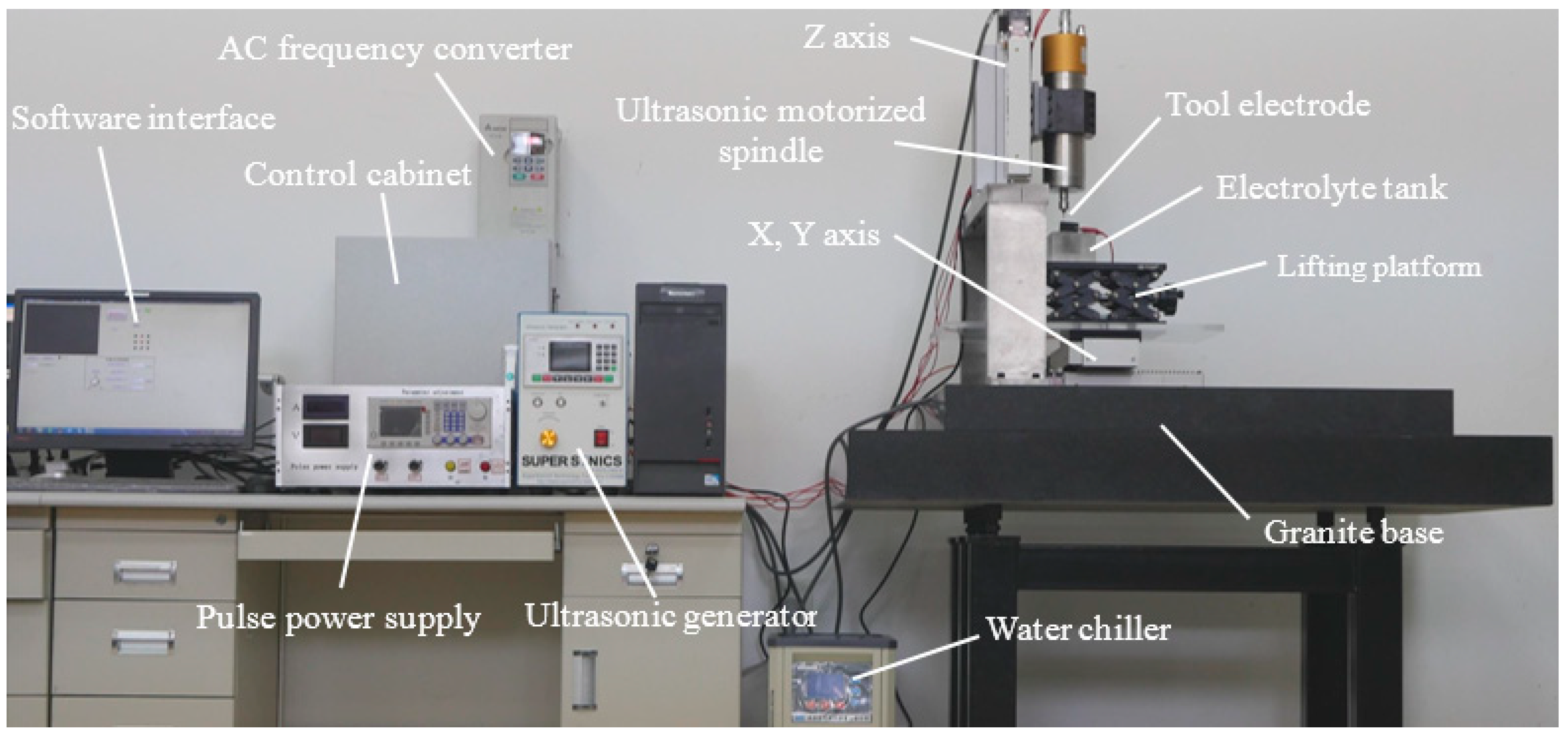
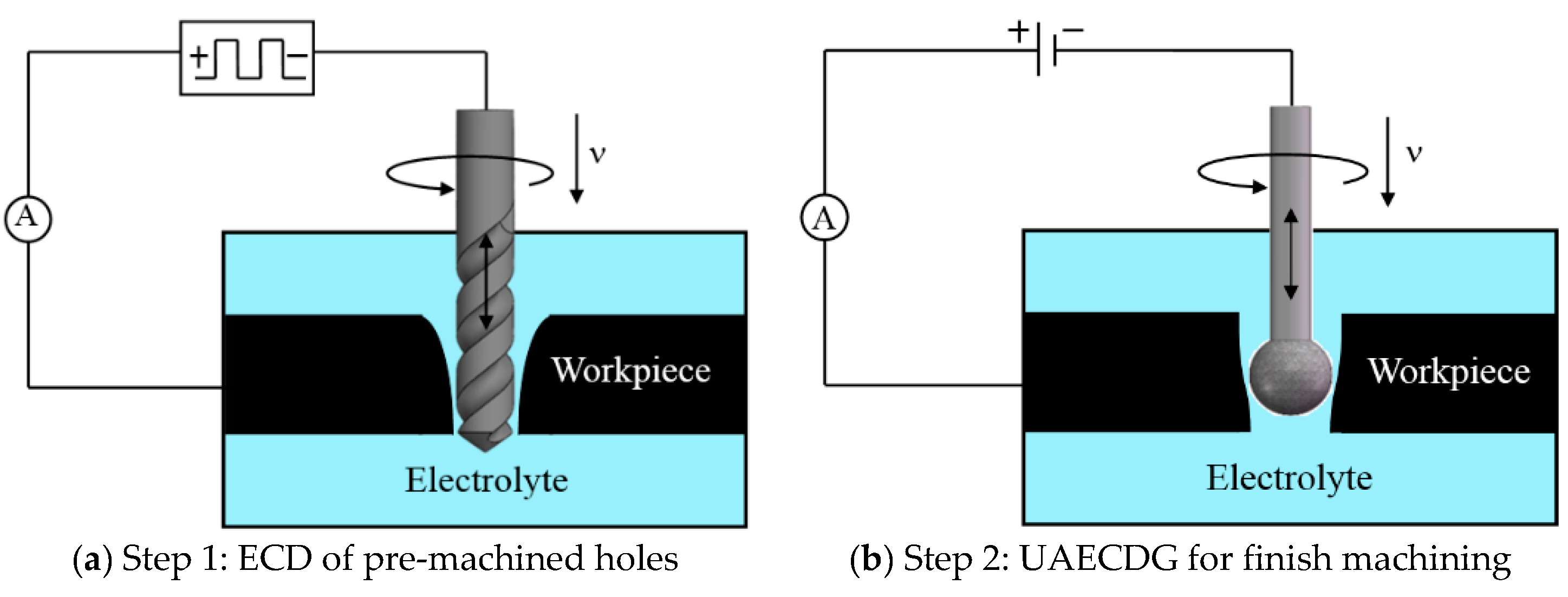
2. Experimental Set-Up and Machining Process Analysis
3. Material and Mathematical Model
3.1. Electrochemical Behavior of Materials
3.2. Mathematical Model
4. Experimental Results and Discussion
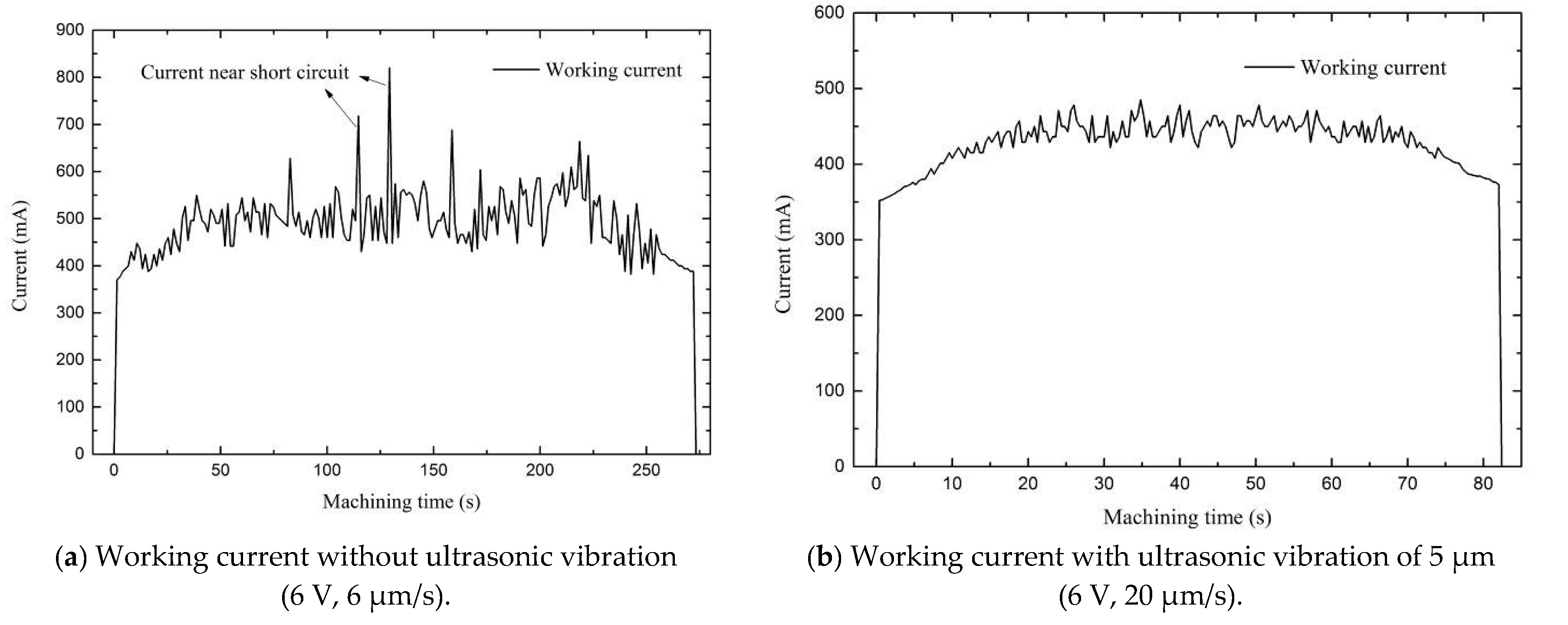
4.1. Influence of Ultrasonic Amplitude
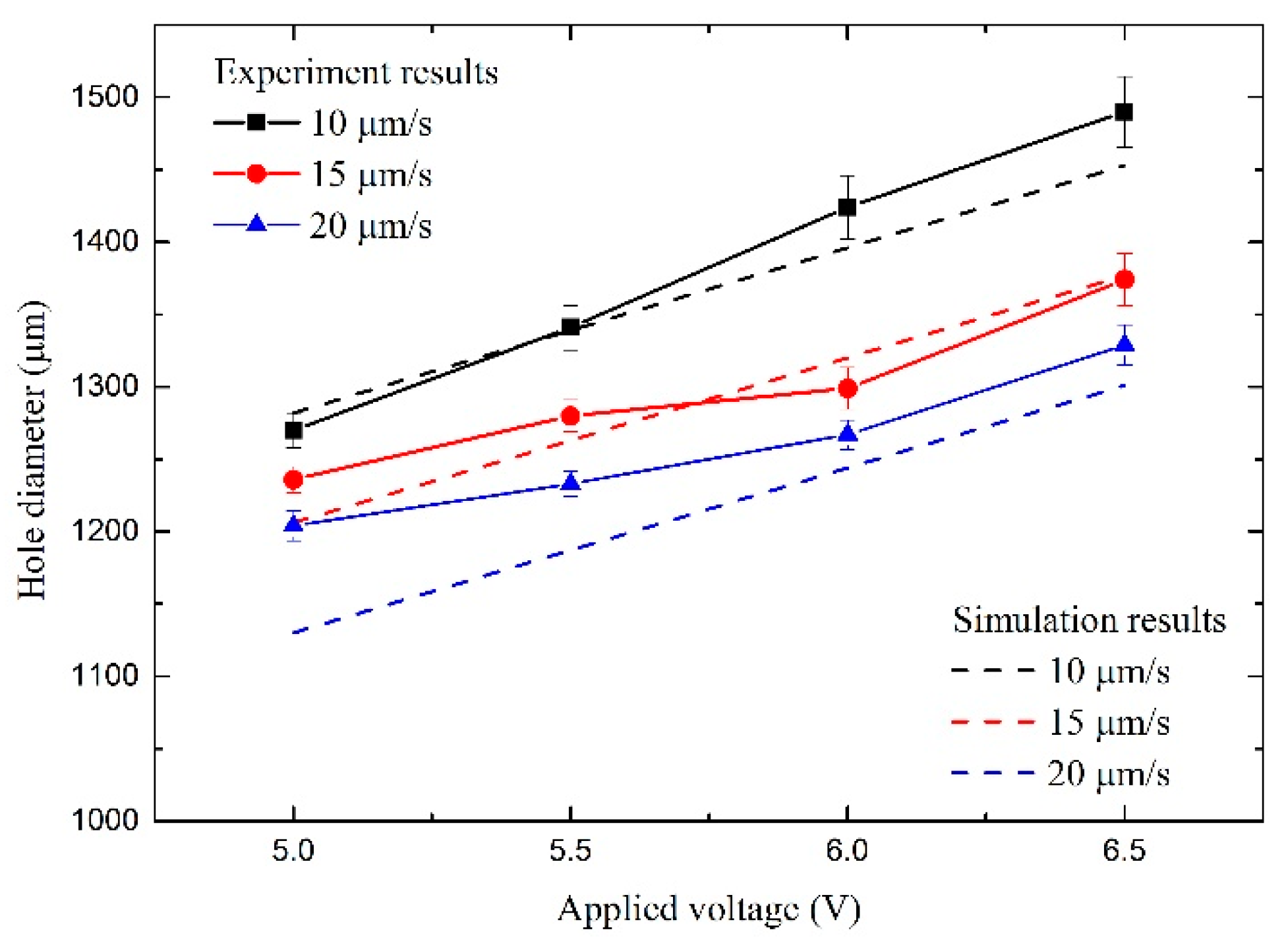
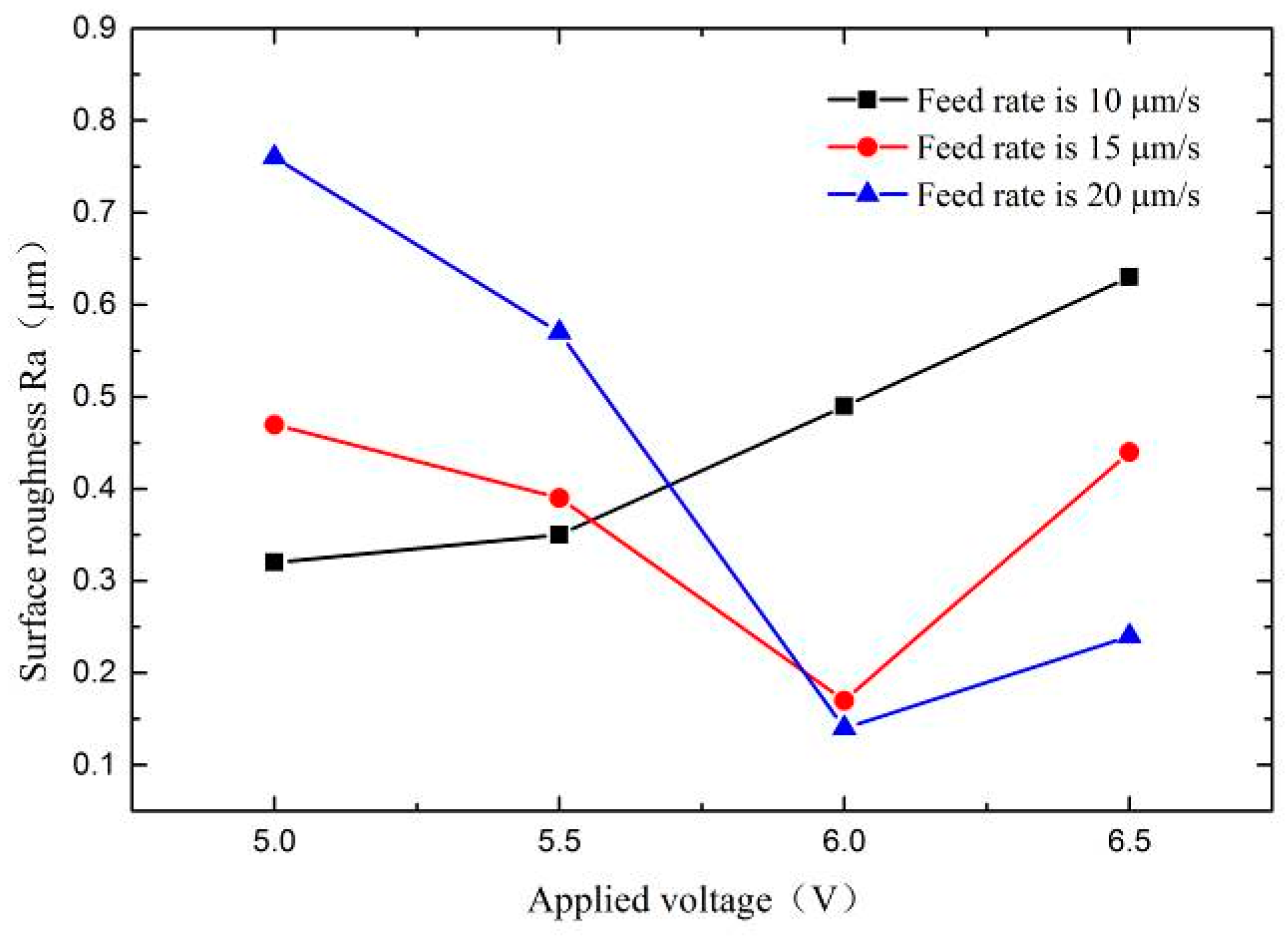
4.2. Influence of Ultrasonic Amplitude Influence of Applied Voltage and Feed Rate
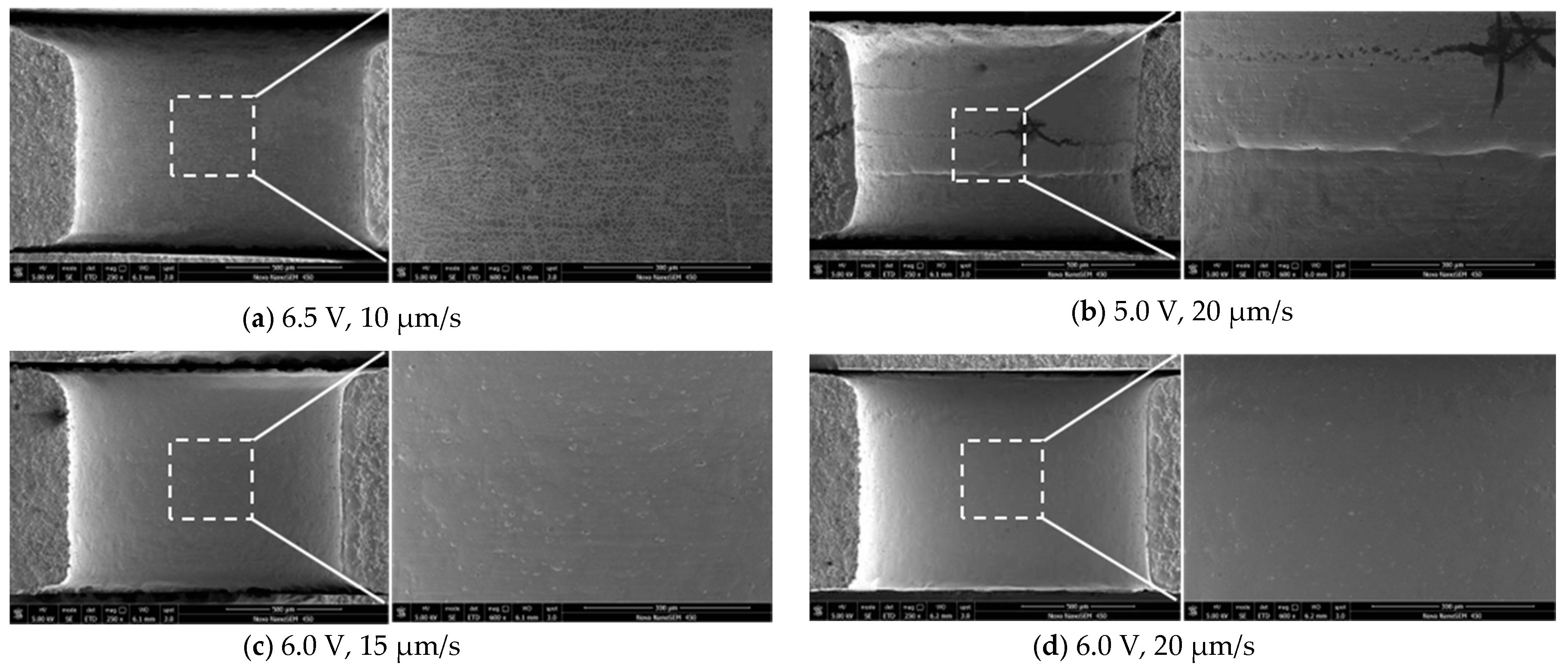
4.3. Experimental Result with Potimized Parameters
5. Conclusions
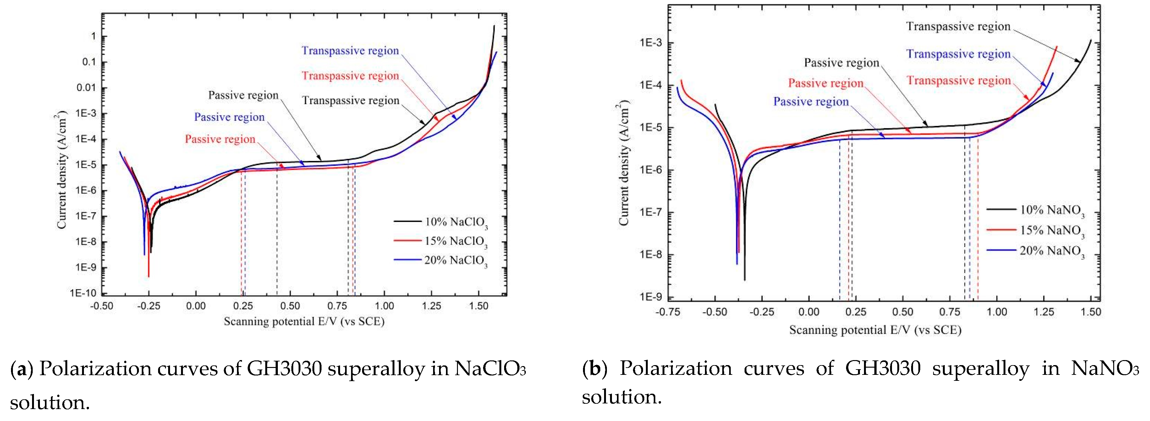
- (1)
- GH3030 superalloy has a passive behavior both in NaNO3 solution and NaClO3 solution. To obtain a stable passivation, the 20% NaNO3 solution is employed as an electrolyte in UAECDG because of the wider passive potential range, as well as the lower passive current density.
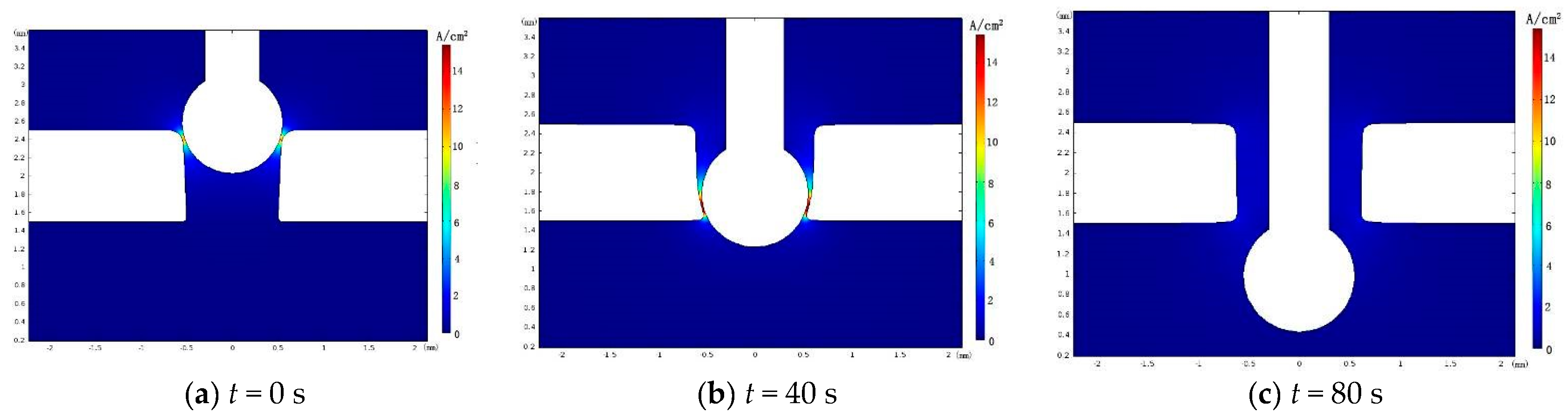
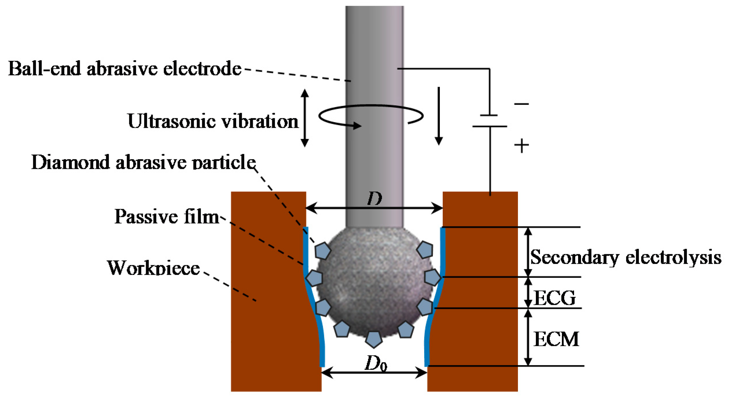
- (2)
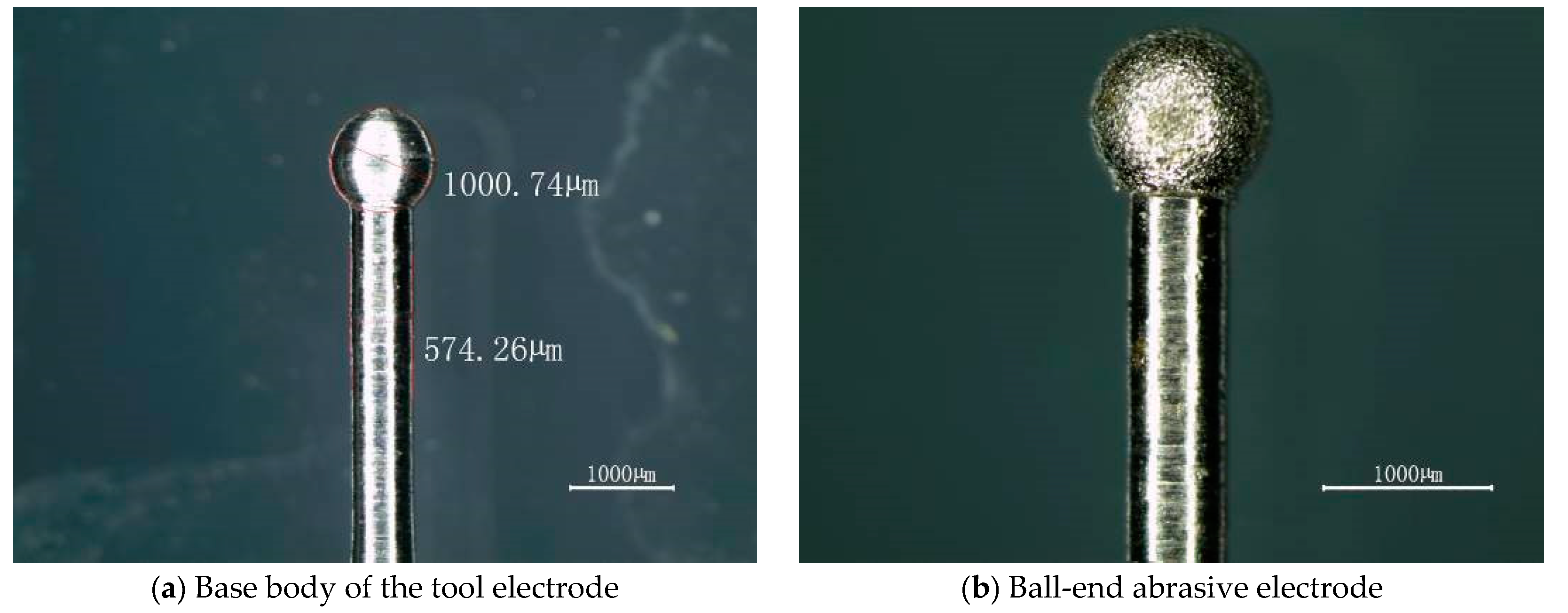
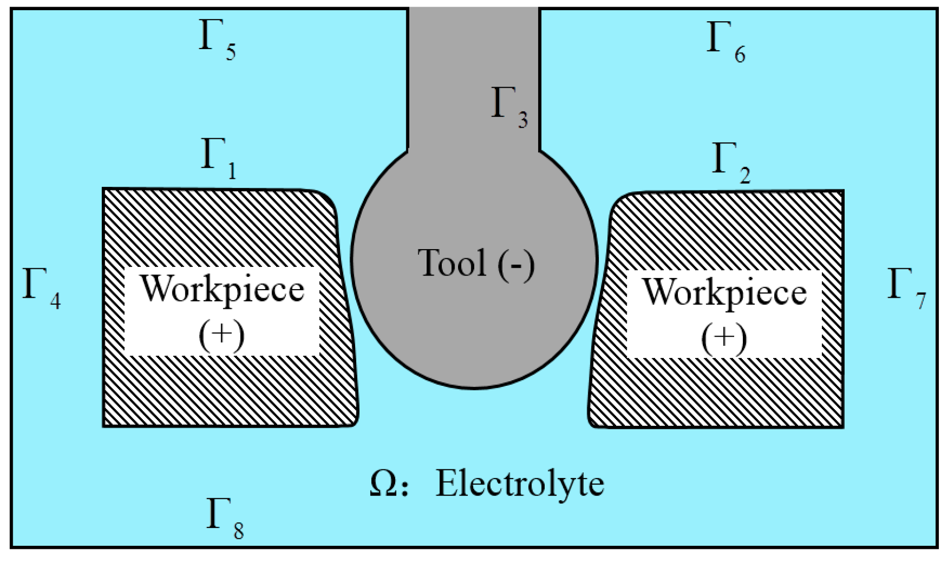
- The electric field simulation of machining gap shows that electrochemical reaction can be restricted to the region around the ball-end of the tool electrode. By using the abrasive electrode with a ball-end, the machining localization can be improved and the hole taper can be reduced. In addition, the experiment results show that the hole wall is straighter after UAECDG by using the ball-end abrasive electrode.
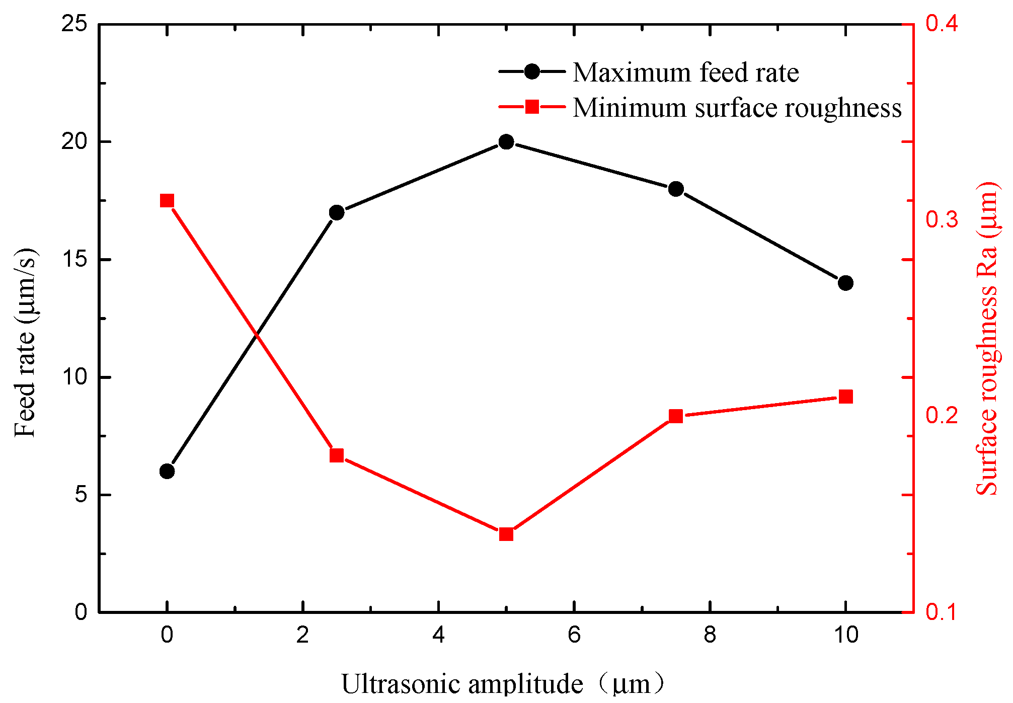
- (3)
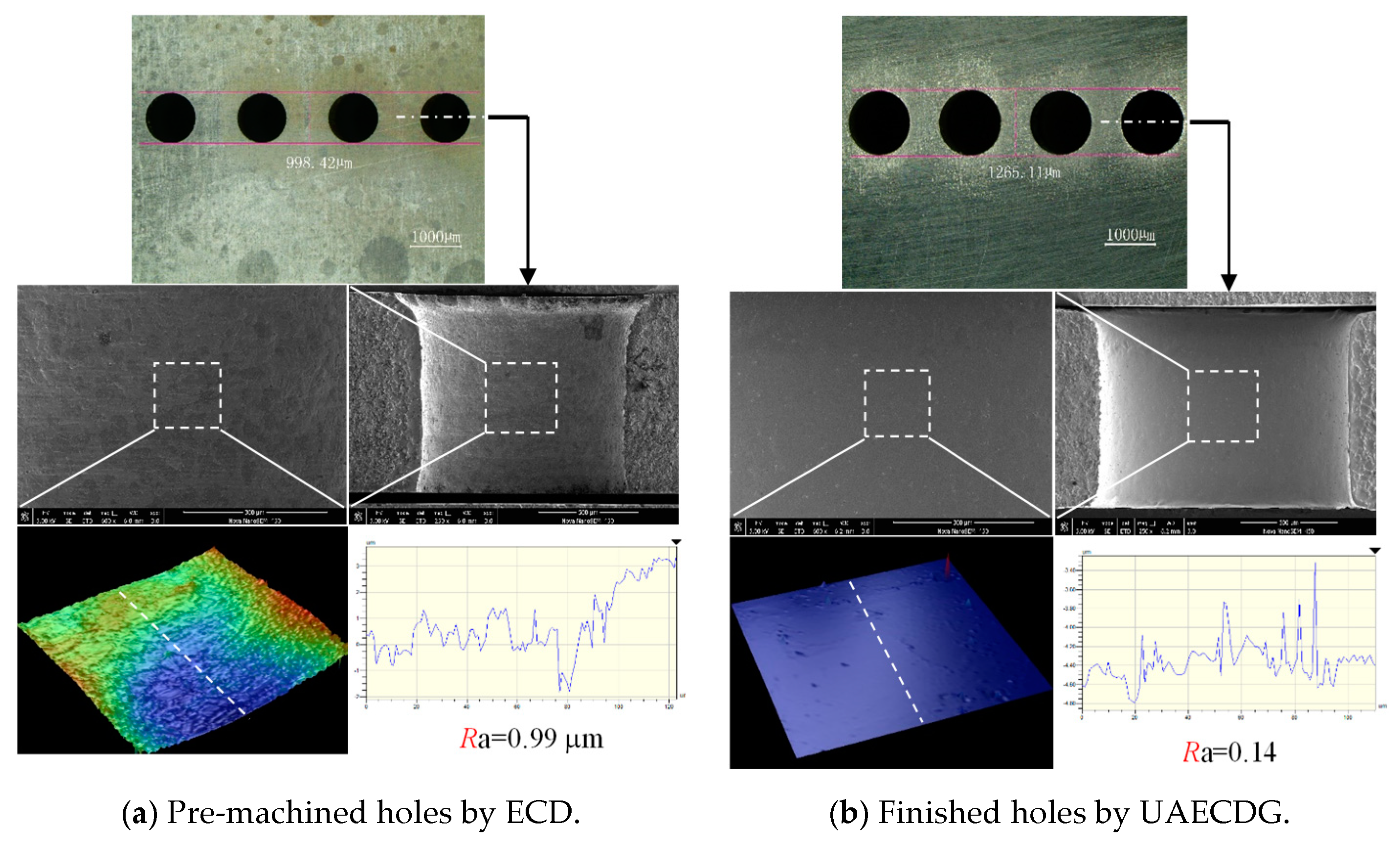
- The surface quality is determined by the balance of ECM and mechanical grinding. By applying an ultrasonic vibration with a proper amplitude on the tool electrode, the refreshment of the electrolyte is promoted and the machining efficiency and stability can be improved significantly. By optimizing the applied voltage, tool feed rate and ultrasonic amplitude, the small holes with high surface quality can be obtained. Compared with the surface machined by electrochemical drilling, the final surface machined by UAECDG is significantly improved with surface quality which demonstrates that the UAECDG is a highly promising technique to machine superalloy with high quality.
Author Contributions
Funding
Conflicts of Interest
References
- Zhan, T.; Chai, F.; Zhao, J.; Yan, F.; Wang, W. A study of microstructures and mechanical properties of laser welded joint in GH3030 alloy. J. Mech. Sci. Technol. 2018, 32, 2613–2618. [Google Scholar] [CrossRef]
- Xue, C.; Chen, W. Adhering layer formation and its effect on the wear of coated carbide tools during turning of a nickel-based alloy. Wear 2011, 270, 895–902. [Google Scholar] [CrossRef]
- Goswami, T. Conjoint bending torsion fatigue—Fractography. Mater. Des. 2002, 23, 385–390. [Google Scholar] [CrossRef]
- Imran, M.; Mativenga, P.; Gholinia, A.; Withers, P.J. Comparison of tool wear mechanisms and surface integrity for dry and wet micro-drilling of nickel-base superalloys. Int. J. Mach. Tools Manuf. 2014, 76, 49–60. [Google Scholar] [CrossRef]
- Zhu, D.; Zhang, X.; Ding, H. Tool wear characteristics in machining of nickel-based superalloys. Int. J. Mach. Tools Manuf. 2013, 64, 60–77. [Google Scholar] [CrossRef]
- Uçak, N.; Çiçek, A. The effects of cutting conditions on cutting temperature and hole quality in drilling of inconel 718 using solid carbide drills. J. Manuf. Process. 2018, 31, 662–673. [Google Scholar] [CrossRef]
- Sinha, M.K.; Setti, D.; Ghosh, S.; Rao, P.V. An investigation on surface burn during grinding of inconel 718. J. Manuf. Process. 2016, 21, 124–133. [Google Scholar] [CrossRef]
- Yılmaz, B.; Karabulut, Ş.; Güllü, A. Performance analysis of new external chip breaker for efficient machining of inconel 718 and optimization of the cutting parameters. J. Manuf. Process. 2018, 32, 553–563. [Google Scholar] [CrossRef]
- Wang, Y.L.; Chen, C.Y.; Liu, Z.C.; Ren, W.X.; Zhu, L.Z.; Wang, L. Machining and characterization of deep micro holes on super alloy processed by millisecond pulsed laser. Key Eng. Mater. 2016, 703, 34–38. [Google Scholar] [CrossRef]
- Pan, Z.; Feng, Y.; Hung, T.-P.; Jiang, Y.-C.; Hsu, F.-C.; Wu, L.-T.; Lin, C.-F.; Lu, Y.-C.; Liang, S.Y. Heat affected zone in the laser-assisted milling of inconel 718. J. Manuf. Process. 2017, 30, 141–147. [Google Scholar] [CrossRef]
- Lee, L.; Lim, L.; Narayanan, V.; Venkatesh, V. Quantification of surface damage of tool steels after EDM. Int. J. Mach. Tools Manuf. 1988, 28, 359–372. [Google Scholar] [CrossRef]
- Kliuev, M.; Florio, K.; Akbari, M.; Wegener, K. Influence of energy fraction in EDM drilling of inconel 718 by statistical analysis and finite element crater-modelling. J. Manuf. Process. 2019, 40, 84–93. [Google Scholar] [CrossRef]
- Rahman, Z.; Das, A.K.; Chattopadhyaya, S. Microhole drilling through electrochemical processes: A Review. Mater. Manuf. Process. 2017, 33, 1379–1405. [Google Scholar] [CrossRef]
- Maksoud, T.; Brooks, A. Electrochemical grinding of ceramic form tooling. J. Mater. Process. Technol. 1995, 55, 70–75. [Google Scholar] [CrossRef]
- Puri, A.B.; Banerjee, S. Multiple-response optimisation of electrochemical grinding characteristics through response surface methodology. Int. J. Adv. Manuf. Technol. 2012, 64, 715–725. [Google Scholar] [CrossRef]
- Curtis, D.; Soo, S.; Aspinwall, D.; Sage, C. Electrochemical superabrasive machining of a nickel-based aeroengine alloy using mounted grinding points. CIRP Ann. 2009, 58, 173–176. [Google Scholar] [CrossRef]
- Goswami, R.N.; Mitra, S.; Sarkar, S. Experimental investigation on electrochemical grinding (ECG) of alumina-aluminum interpenetrating phase composite. Int. J. Adv. Manuf. Technol. 2008, 40, 729–741. [Google Scholar] [CrossRef]
- Li, H.; Fu, S.; Zhang, Q.; Niu, S.; Qu, N. Simulation and experimental investigation of inner-jet electrochemical grinding of GH4169 alloy. Chin. J. Aeronaut. 2018, 31, 608–616. [Google Scholar] [CrossRef]
- Ming, P.M.; Zhu, D.; Xu, Z.Y. Electrochemical grinding for unclosed internal cylinder surface. Key Eng. Mater. 2007, 359, 360–364. [Google Scholar] [CrossRef]
- Zhu, D.; Zeng, Y.; Xu, Z.; Zhang, X. Precision machining of small holes by the hybrid process of electrochemical removal and grinding. CIRP Ann. 2011, 60, 247–250. [Google Scholar] [CrossRef]
- Qu, N.; Zhang, Q.; Fang, X.; Ye, E.; Zhu, D. Experimental investigation on electrochemical grinding of inconel 718. Procedia CIRP 2015, 35, 16–19. [Google Scholar] [CrossRef]
- Przystupa, K.; Litak, G. Electrochemical grinding of titanium-containing materials. Adv. Sci. Technol. Res. J. 2017, 11, 183–188. [Google Scholar] [CrossRef][Green Version]
- Li, H.; Niu, S.; Zhang, Q.; Fu, S.; Qu, N. Investigation of material removal in inner-jet electrochemical grinding of GH4169 alloy. Sci. Rep. 2017, 7, 3482. [Google Scholar] [CrossRef] [PubMed]
- Li, H. Simulation and experimental investigation of electrochemical mill-grinding of GH4169 alloy. Int. J. Electrochem. Sci. 2018, 13, 6608–6625. [Google Scholar] [CrossRef]
- Niu, S.; Qu, N.; Yue, X.; Li, H. Effect of tool-sidewall outlet hole design on machining performance in electrochemical mill-grinding of inconel 718. J. Manuf. Process. 2019, 41, 10–22. [Google Scholar] [CrossRef]
- Niu, S.; Qu, N.; Li, H. Investigation of electrochemical mill-grinding using abrasive tools with bottom insulation. Int. J. Adv. Manuf. Technol. 2018, 97, 1371–1382. [Google Scholar] [CrossRef]
- Ge, Y.; Zhu, Z.; Wang, D.; Ma, Z.; Zhu, D. Study on material removal mechanism of electrochemical deep grinding. J. Mater. Process. Technol. 2019, 271, 510–519. [Google Scholar] [CrossRef]
- Zhu, X.; Liu, Y.; Zhang, J.; Wang, K.; Kong, H. Ultrasonic-assisted electrochemical drill-grinding of small holes with high-quality. J. Adv. Res. 2020, 23, 151–161. [Google Scholar] [CrossRef]
- Liu, Y.; Li, M.; Niu, J.; Lu, S.; Jiang, Y. Fabrication of taper free micro-holes utilizing a combined rotating helical electrode and short voltage pulse by ECM. Micromachines 2019, 10, 28. [Google Scholar] [CrossRef]
- Wang, D.; Zhu, Z.; Wang, N.; Zhu, D.; Wang, H. Investigation of the electrochemical dissolution behavior of inconel 718 and 304 stainless steel at low current density in NaNO3 solution. Electrochim. Acta 2015, 156, 301–307. [Google Scholar] [CrossRef]


| Item | Value |
|---|---|
| Diameter of the pre-machined hole | 1 mm |
| Diameter of the ball-end | 1.1 mm |
| Diameter of the rod | 0.6 mm |
| Thickness of the workpiece | 1 mm |
| Electrical conductivity of the electrolyte | 11.6 S/m |
| Applied voltage | 6 V |
| Feed rate | 20 μm/s |
| Item | Value |
|---|---|
| Diameter of the pre-machined hole | 1 mm |
| Diameter of tool electrode ball-end | 1.1 mm |
| Electrolyte | 20% NaNO3 solution |
| Rotating speed of tool electrode | 12,000 r/min |
| Applied voltage | 5.06.5 V |
| Feed rate | 10–20 μm/s |
| Ultrasonic amplitude | 0–10 μm |
| Ultrasonic frequency | 25 kHz |
© 2020 by the authors. Licensee MDPI, Basel, Switzerland. This article is an open access article distributed under the terms and conditions of the Creative Commons Attribution (CC BY) license (http://creativecommons.org/licenses/by/4.0/).
Share and Cite
Kong, H.; Liu, Y.; Zhu, X.; Peng, T. Study on Ultrasonic Assisted Electrochemical Drill-Grinding of Superalloy. Chemosensors 2020, 8, 62. https://doi.org/10.3390/chemosensors8030062
Kong H, Liu Y, Zhu X, Peng T. Study on Ultrasonic Assisted Electrochemical Drill-Grinding of Superalloy. Chemosensors. 2020; 8(3):62. https://doi.org/10.3390/chemosensors8030062
Chicago/Turabian StyleKong, Huanghai, Yong Liu, Xiangming Zhu, and Tengfei Peng. 2020. "Study on Ultrasonic Assisted Electrochemical Drill-Grinding of Superalloy" Chemosensors 8, no. 3: 62. https://doi.org/10.3390/chemosensors8030062
APA StyleKong, H., Liu, Y., Zhu, X., & Peng, T. (2020). Study on Ultrasonic Assisted Electrochemical Drill-Grinding of Superalloy. Chemosensors, 8(3), 62. https://doi.org/10.3390/chemosensors8030062