1. Introduction
The accidental discovery of carbon quantum dots (CQDs) occurred in 2004 as reported by Xu et al. [
1] during the purification of single-walled carbon nanotubes (SWNTs) produced by arc-discharge soot. In that context, short tubular carbon and a mixture of fluorescent nanoparticles were isolated. This was the origin of CQDS, paving the way to a twofold outcome: two classes of nanomaterials from the SWNTs and a breakthrough in photoluminescence (PL) materials [
2]. Although both exhibit nanosized characteristics, a crucial distinction should be made between carbon quantum dots being small semiconductor nanoparticles of all kinds, while the carbon dots (CDs) are small carbon nanoparticles. The term ‘dots’ implies a 0-dimensional material, while the term ‘quantum dots’ indicates nano-scale semiconductors, neither metal nor insulator materials. Carbon dots are the 0-dimensional structures belonging to the carbon material class, which are highly versatile and cannot be divided exactly into metal, semiconductor, or insulator. In the results, we designate the CDs as carbon materials without making the distinction whether the carbon materials are metal [
3], semiconductor [
4], or insulator [
5]. Briefly, it could be stated that all CQDs are CDs, but not all CDs are CQDs.
In recent years, there has been a development in in-depth research on the process for the production of CDs [
6] connected to their emerging applications in imaging, sensing, and anti-counterfeiting, to name a few. Typically, CDs consist of carbon and oxygen, and the large number of carboxyl and epoxy functional groups on their surfaces induces non-radiative recombination between surface electrons and holes, which results in low luminescence. These CDs [
7] are usually produced from natural products or synthetic organic compounds through microwave or hydrothermal processes. The functionalization of the CDs is being widely investigated for the enhancement of their photophysical and photochemical properties.
To assist the functionalization of the CDs, it is possible to move from single-source to multi-component synthesis even if in this case special attention should be dedicated to the purification stage; using different isomers of the same precursor [
8]; using the same starting materials and different solvents [
9,
10]; introducing additives [
11,
12] to increase the content of heteroatoms to yield the fluorescence to red (nitric acid helping the formation of the conjugated π system.) or yellow. Indeed, it is known that the introduction of types of heteroatoms, as well as their location, is adapted to tune the emission wavelength of CDs.
The doping of CDs means modifying their surfaces by inducing reactions with small molecules to provide new functionalities and broaden their applications. CDs with respect to traditional organic dyes, inorganic quantum dots, and perovskite quantum dots exhibit wide emission and narrow half-width characteristics, higher stability, and low toxicity, which are not typical features that belong to fluorescent materials [
13,
14]. Although CDs have been produced from several types of raw material and fascinating luminescence properties have been studied on the basis of their structural diversity, as well as their biocompatibility [
15,
16], the relations between the surface properties, the crystalline and/or amorphous structures and shape of CDs, their solubility, their optical properties, and their luminescence mechanism are still a source of debate.
The mainstream agreement assigns the absorption peaks in the ultra-violet (UV) region below 280 nm to π-π* transitions of the C=C bonds in the carbon core; the one located at 320–350 nm is assigned to
n-π* transitions of the C=O bonds at the CDs edge [
17]. In case of the amino-functionalized CDs, the luminescence peaks located at 420–460 nm are assigned to
n-π* transitions and seem to be due to the doping of CDs with oxygen and nitrogen heteroatoms [
18]. A large majority of the published works describe the preparation of CDs by chemical processes, such as surface passivation, synthesis from candle soot, or the hydrothermal carbonization of citric acid [
19,
20]. Kalytchuk et al. [
21] realized highly sensitive temperature sensing based on in vitro photoluminescence of CDs prepared using citric acid and cysteine as raw materials. It is worth remembering that these approaches usually involve complex processes and severe synthesis conditions; frequently, the results are toxic byproducts. Alternative and successful approaches adopted for the synthesis of such luminescent carbon nanostructures are electrochemical oxidation [
22], microwave synthesis [
23], and organic carbonization [
24]. The recent literature mentions the use of pulsed lasers as a promising method for the synthesis of CDs at moderate cost, without the need for vacuum systems and using an easily implemented setup. Pulsed laser systems have a long record in fundamental research [
25], material modification [
26], and production of nanoparticles [
27,
28]. It seems that carbon nanoparticles produced by pulsed laser ablation (PLA) in water reveal trivial fluorescence with respect to when other liquids like acetone, isopropyl alcohol, polyethylene glycol, ethylenediamine, or polyethyleneimine are used [
29]. In the routine PLA process, laser pulses, even with high repetition rates, produce cavitation bubbles that shield the next laser pulses. The subsequent loss of the laser energy impacting the target reduces the production rate of CDs [
30].
In this frame, to the best of our knowledge, following the research introduced by our scientific group, for the first time, CDs have been generated using easily available and low-cost charcoal by continuous laser ablation, leading to higher productivity of CDs. This used phosphate-buffered saline (PBS) as liquid, which is a 100% biocompatible solution, removing any need for the integration of activators or typically used reagents, avoiding any requirement for a purification process. Over again, the effect of the illumination of UV light at a wavelength of 365 nm is compared to that of 2 MeV and 800 keV energy ions irradiating a suspension of CDs for the first time, as far as we know.
The electronic energy deposition, produced by MeV proton beams, is employed to induce luminescence in CDs produced by laser ablation of CDs in PBS solutions, which has never been reported before in the literature. Probably the generation of electron levels within the CDs band gap energy is responsible for the luminescence shifts towards the high wavelength region. Our results lead the way to the use of carbon dots surface functionalized for the design of new materials suitable for the production of dosimeters, detectors for ionizing radiation.
2. Materials and Methods
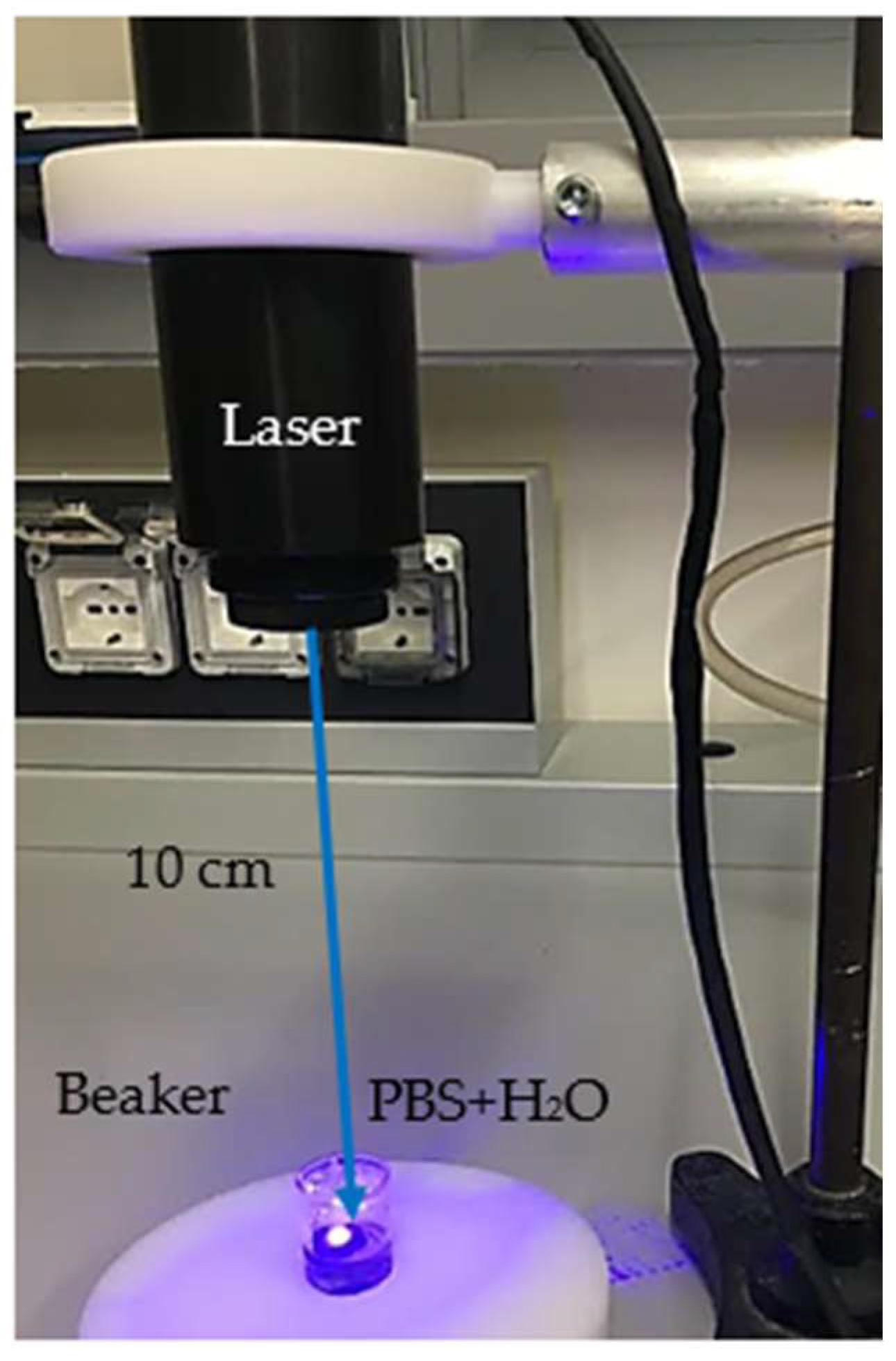
A semiconductor laser system, later denominated ‘blue laser’, operating at a wavelength of 450 nm was used in continuous wave (CW) mode, at an output power of 50 W, and intensity of 5 × 10
3 W/cm
2, and with a beam size of about 1 mm × 5 mm. A phosphate-buffered saline (PBS) tablet, having a weight of 2 g, purchased from Sigma Aldrich (Milan, Italy), was dissolved in 200 mL of deionized water [
31]. A piece of charcoal in a rectangular shape of 1.1 cm
2 surface and 0.15 cm thickness was used as the primary target. It was located in a glass vessel containing 4 mL of PBS at a controlled pH of 7.
Figure 1 shows the setup employed for the CDs’ preparation [
32].
The carbon target has a volume of 0.165 cm3 and a mass of about 0.110 g, corresponding to a density of 0.67 g/cm3.
The target was covered by 1 mm of liquid, and laser irradiations, generally, had a duration of 180 min. The weight of the charcoal after 3 h of CW laser irradiation was about 0.108 g, indicating a removal of 0.002 g.
Ten substrates of Al having the same thickness and smoothness were selected to reduce any possible error due to different surface tension and CDs droplet spreading. Then, these metallic substrates were covered with 1 μL of suspension containing CDs. To assess the layer uniformity, the same drying rate and temperature were used, and all the samples were prepared the same day using a spin coating system. The slight variation of the layer thickness could be associated with the uneven concentration of CDs contained in the amount of suspension poured onto the Al substrates. The error associated with the preparation of the target dedicated to the proton irradiation could be connected to different CDs concentrations in the layer reacting differently to the ion irradiation.
2.1. Laser Ablation in Liquid
The laser ablation in liquid can be considered a simple technique, although it is based on the accurate control of the laser irradiation parameters (irradiation time, repetition rate, pulse duration, and wavelength). Further important parameters are connected to the liquid features like pH and dielectric constant [
33]. The laser is pointed towards a glass vessel containing the charcoal target immersed in liquid. The laser beam with a size of 1 mm × 5 mm passes through 1 mm of liquid and then hits the surface of the target. During the path of the laser beam to the target surface, part of the laser energy is reflected, part is scattered, and most is absorbed. This results in an increase in the temperature at the solid/liquid surface of the order of several kilokelvins, and leads to the generation of a plasma. This plasma, confined by the liquid, expands and then condenses, forming a vapor layer. The progressive expansion of the vapor layer induces a cavitation bubble. Subsequently, the plasma shrinks with the compression of the vapor of about several GPa, starting a chemical interaction between vaporized liquid and ablated material [
34]. When the bubble is broken, the new solid phase structures formed at the plasma–liquid interface are first dispersed in the liquid, and then they grow until they cool down to the same temperature as the liquid [
35].
2.2. Luminescence Induced by UV and Proton Irradiation
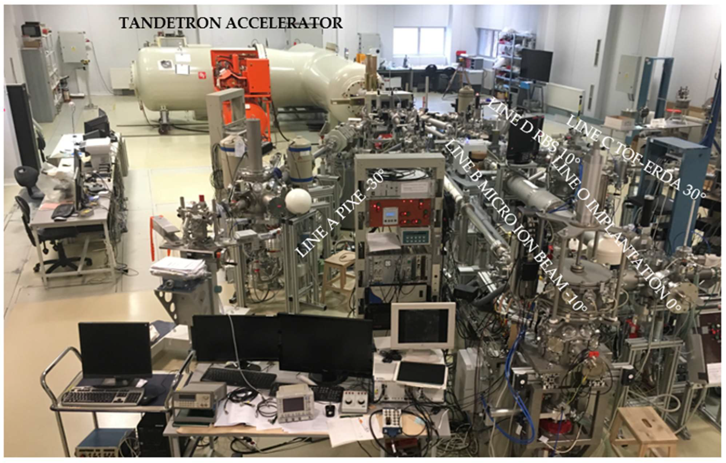
The substrates of Al covered with a thin layer of CDs suspension were placed in the holder inside a vacuum chamber. Following the different stopping power, proton ions with energies of 2 MeV and 800 keV were released from a Tandetron accelerator and sent to the line A located at −30°.
Figure 2 reports a photo of the Tandetron Laboratory at the Nuclear Physics Institute (Rez, Czech Republic) where measurements were performed.
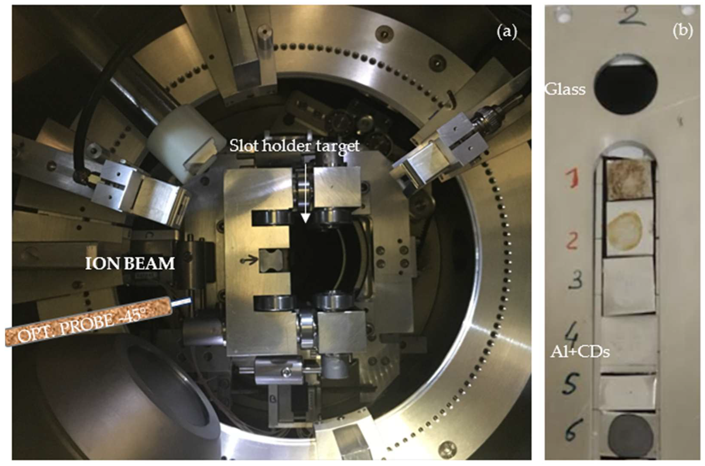
Figure 3 displays the vacuum chamber at
line A, and it reports the incoming proton ions at a 0° incident angle in the center of the slot where the sample holders are located.
The Avantes optical spectrometer AvaSpec-2048-USB2, Apeldoorn, Netherlands is indicated in
Figure 3 as opt. probe was set inside the vacuum chamber and connected to a dedicated PC for the monitoring and collection of the measurements and the storing of the optical spectra. The integration time was 10 s, and the acquired spectra were not smoothed.
A 2 MeV H
+ beam collimated to 4 mm × 4 mm was delivered by the 3 MeV Tandetron accelerator [
36]. The ion current of 32 nA was measured at the beginning and the end of the irradiation using a Faraday cup located at the entrance of the vacuum chamber.
2.3. Morphological Characterization of the CDs
The size and shape of the CDs obtained by laser ablation in liquid were examined by Atomic Force Microscopy (AFM). The study of material surface morphology was performed using the atomic force microscope Dimension ICON (Bruker Corp., Bremen, Germany). ScanAsyst® mode in air was applied with a silicon tip on Nitride Lever SCANASYST-AIR and a spring constant of 0.4 Nm−1. Two scan sizes of 300 nm2 and 3 µm2 were acquired.
The samples studied were set by depositing the obtained suspension on a silicon wafer under the same conditions used for the production of the Al substrates covered by the CDs suspension.
3. Results and Discussion
Assuming a spherical shape for the produced CDs with a size of about 10 nm in diameter, and three hours of laser irradiation of the charcoal immersed in PBS, the number of nanoparticles/cm
3 produced should be of the order of 4.7 × 10
15.
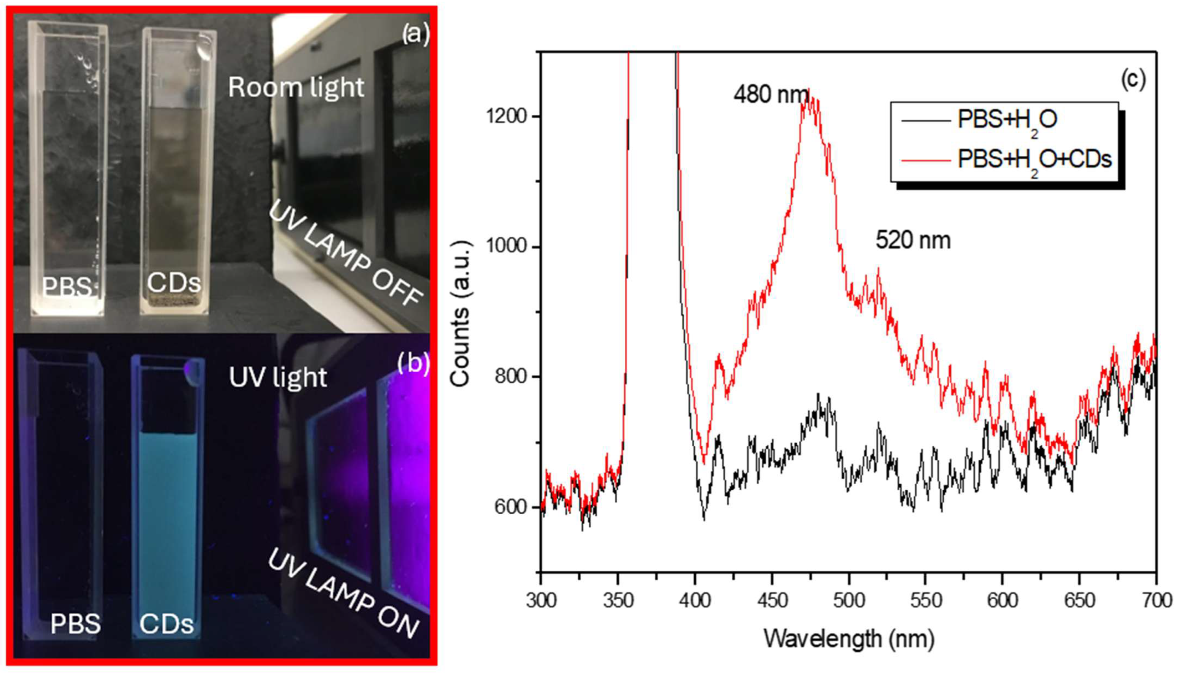
Figure 4 shows quartz cuvettes containing the pristine PBS and CDs suspensions illuminated by room light (see
Figure 4a) and then by UV light (see
Figure 4b). Under UV exposition, the cuvette containing the CDs is luminescent while the cuvette containing only PBS is merely visible.
Figure 4c shows the luminescence spectrum revealed when both the cuvettes without and with CDs are illuminated by UV light at 365 nm. The excitation peaks are visible at 480 nm and 520 nm in both cases. However, the presence of CDs significantly amplifies the luminescence at 480 nm as mentioned in ref. [
37].
The maximum number of counts for PBS + H
2O was about 780, while for PBS + H
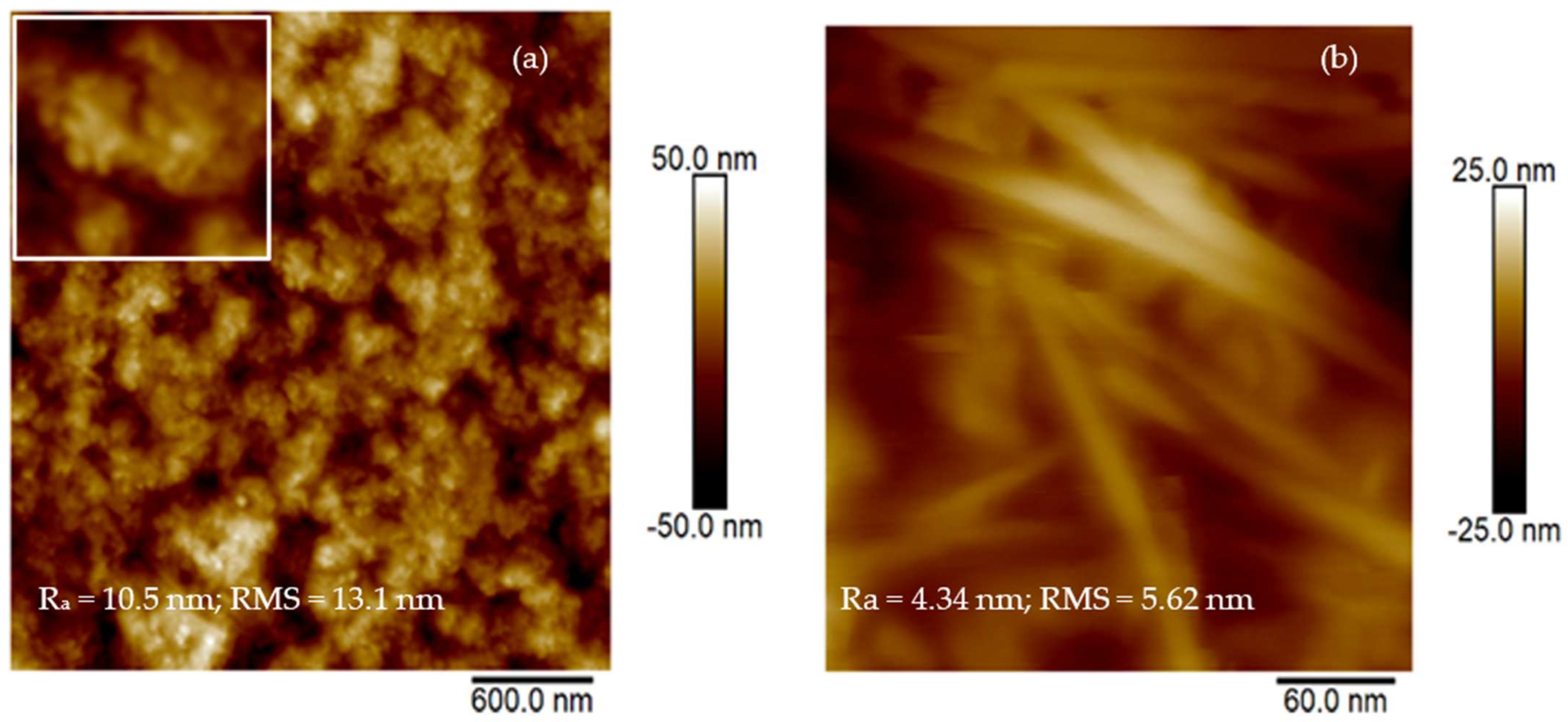
2O + CDs it was more than 1200 counts. For further confirmation of the presence of CDs in the suspension prepared by continuous laser ablation in liquid, AFM analysis was performed as shown in
Figure 5a. An inset in a white frame has been included in
Figure 5a for a better visualization of the formed structures.
The average size of the produced CDs is about 10 nm.
Figure 5b reports the presence of structures resembling CNT with a size of about 20 nm and a length of the order of microns, in agreement with the literature [
38].
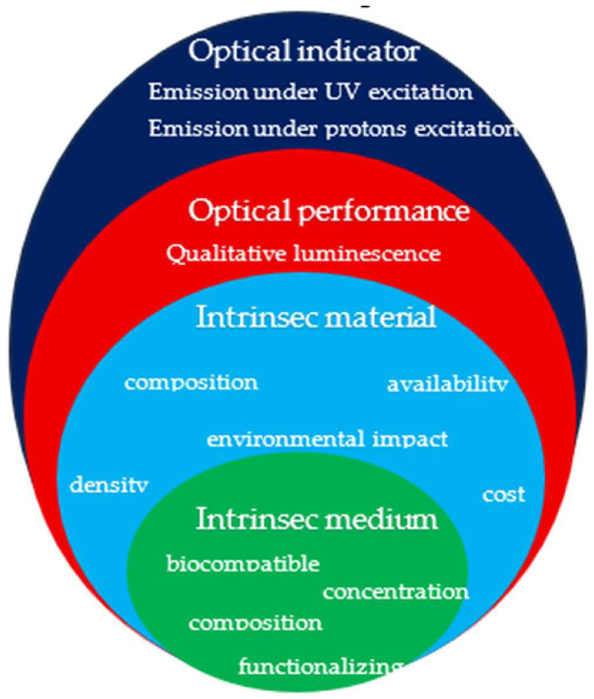
To design and compare the performance of the CDs produced by laser ablation, the Key Performance Indicators (KPIs) have been included (see
Figure 6). KPIs are classified into four main groups: (1) intrinsic medium properties related to composition and concentration of components with respect the solvent (water) content; (2) intrinsic material properties related to composition, density, and porosity of the charcoal used as primary material for the production of CDs by laser ablation; (3) optical performance of the CDs suspension related to qualitative luminescence under excitation of UV light, (4) optical indicators related to the behavior and yield under excitation of UV light and proton ions at two different energies.
Once the luminescence of produced CDs was proven under UV irradiation, we proceeded to investigate the effectiveness of proton ions as a source of excitation for the luminescence of CDs.
Figure 7 reports the comparison of the luminescence emission spectra vs. wavelength of an Al substrate covered with a thin film of CDs under UV with exposition times of 10 s (
Figure 7a) and 100 s (
Figure 7b).
Figure 7 suggests that the film, formed by 1 μL of CDs dried on the surface of Al, does not induce a luminescence identifiable from the background.
The excitation peak around 365 nm, produced by the UV lamp, is clearly visible, while the emission peak at 480 nm is absent, probably due to the low thickness of the layer or the concentration of CDs contained in the suspension deposited on the Al substrate. The obtained spectra suggest that Al covered with a thin film of CDs is not luminescent under UV excitation.
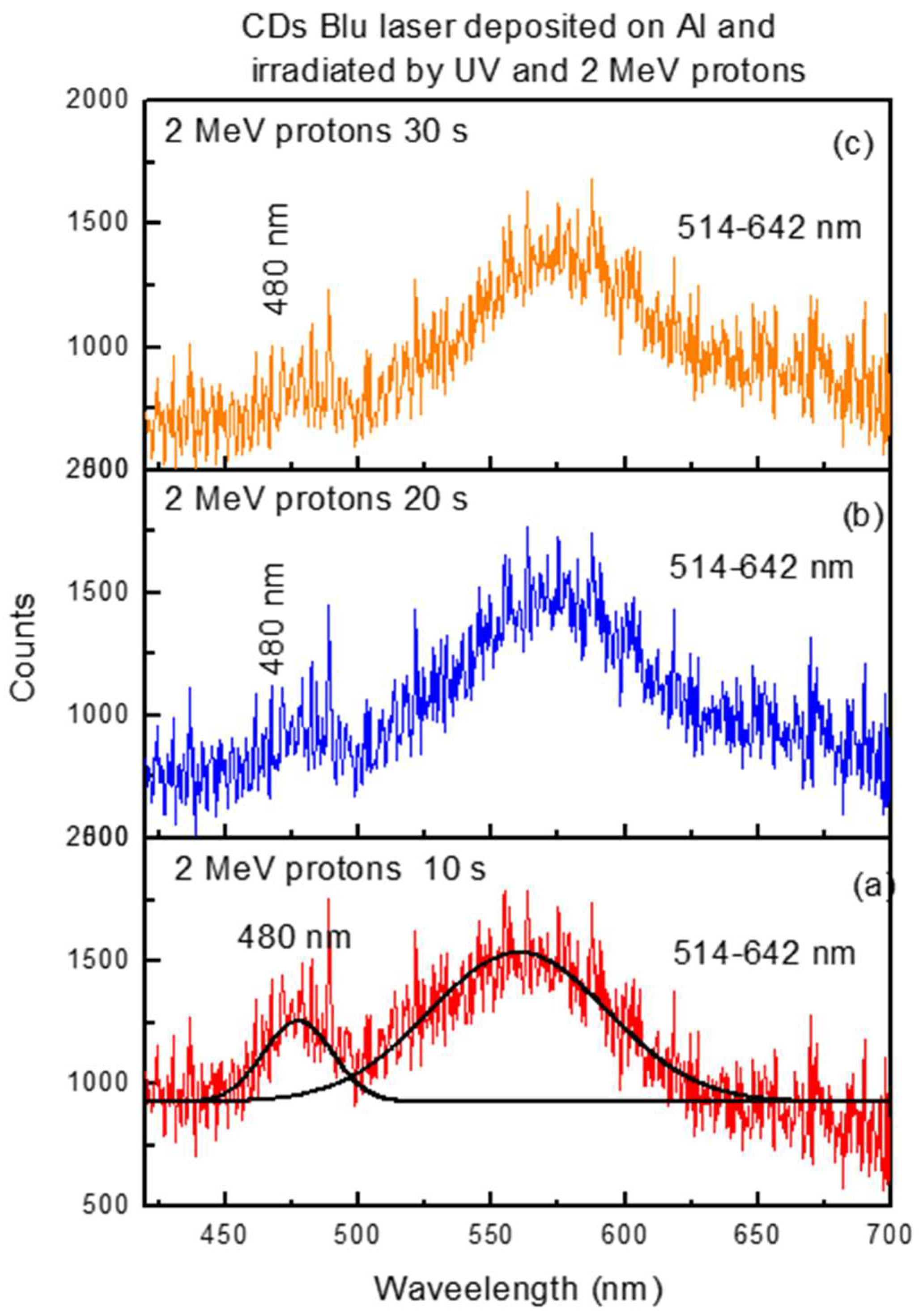
Figure 8 reports the photoluminescence emission spectra exhibited by the same volume of CDs suspension covering the Al substrate with respect to the wavelength from 420 nm to 700 nm, excited by 2 MeV protons. This indicates that proton ions engender luminescence even at low concentrations of CDs, amplifying the effect over the case of excitation from UV, shown in
Figure 7.
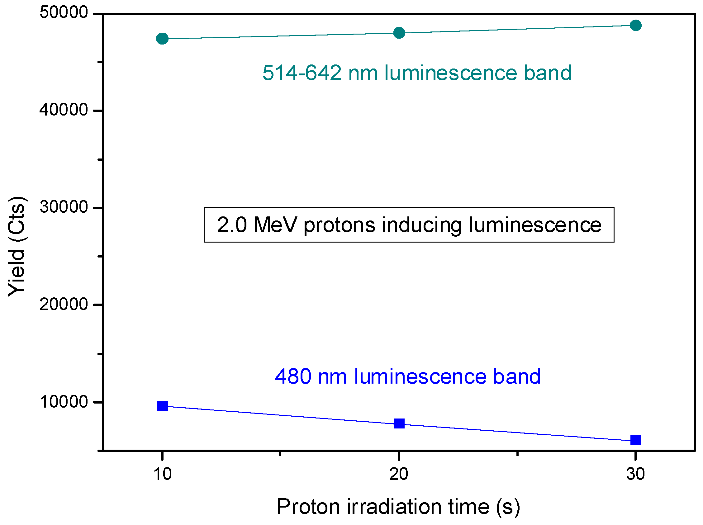
Assuming the two bands centered at 480 nm and at 560 nm have a Gaussian shape, their areas were evaluated in the range of 460–500 nm and 520–640 nm, respectively, and reported in
Figure 9.
The yield of the luminescence induced by two different proton energies as a function of the ion irradiation time was monitored for 10 s, 20 s, and 30 s.
It is evident that proton ions induce excitation and deexcitation of electrons between the valence band and the conduction band, with emission around 480 nm more significant than between the intermediate levels of the bands, with emission of less energetic photons in the visible band between 514 nm and 642 nm.
Figure 9 clearly shows that the luminescence in the band centered at 480 nm decreases with the irradiation time of protons.
Figure 9 shows a relatively weak photoemission upon 2 MeV energy proton irradiation. The weak yield could be ascribable to the low thickness of the layer containing CDs or to the concentration of CDs contained in the used suspension. However, this issue could be solved by increasing the layer thickness and/or the concentration of CDs. Indeed, in both cases, the higher number of CDs is expected to enhance the optical density of the suspension, leading to improved light absorption. This would generate many sites for exciton [
39] production because of the wider cross-section for the interaction with photons.
It might be valuable, in this frame, to remind ourselves that in the case of dominant electronic stopping power, the energy loss of ions in a material containing CDs is mainly transferred to electrons. This leads to a higher number of excitations responsible for photoemission.
The deposition of proton energy observed in our study is due more to the electronic contribution than the nuclear one, as confirmed by the SRIM code [
40] and reported in
Table 1.
Table 1 lists the stopping powers for 2 MeV and 800 keV proton ions to prove the dominant contribution of the electron stopping power over the nuclear stopping power.
The electronic stopping power assumes a value of about 32 keV/mm in the first case and 60 keV/mm in the second case, respectively, which are higher with respect to the nuclear stopping power values.
The beam of ions induces a degradation of the luminescence as a consequence of the deposition of the proton energy on the surface covered with CDs. Indeed, the yield at 480 nm decreases with the increase in the irradiation time, that is, with the dose released on the thin film containing CDs. At 514–642 nm, it seems that a slight increase occurs, maybe due to the presence of carbon nanotubes (CNT), which could be produced together with CDs, as confirmed in the literature [
38].
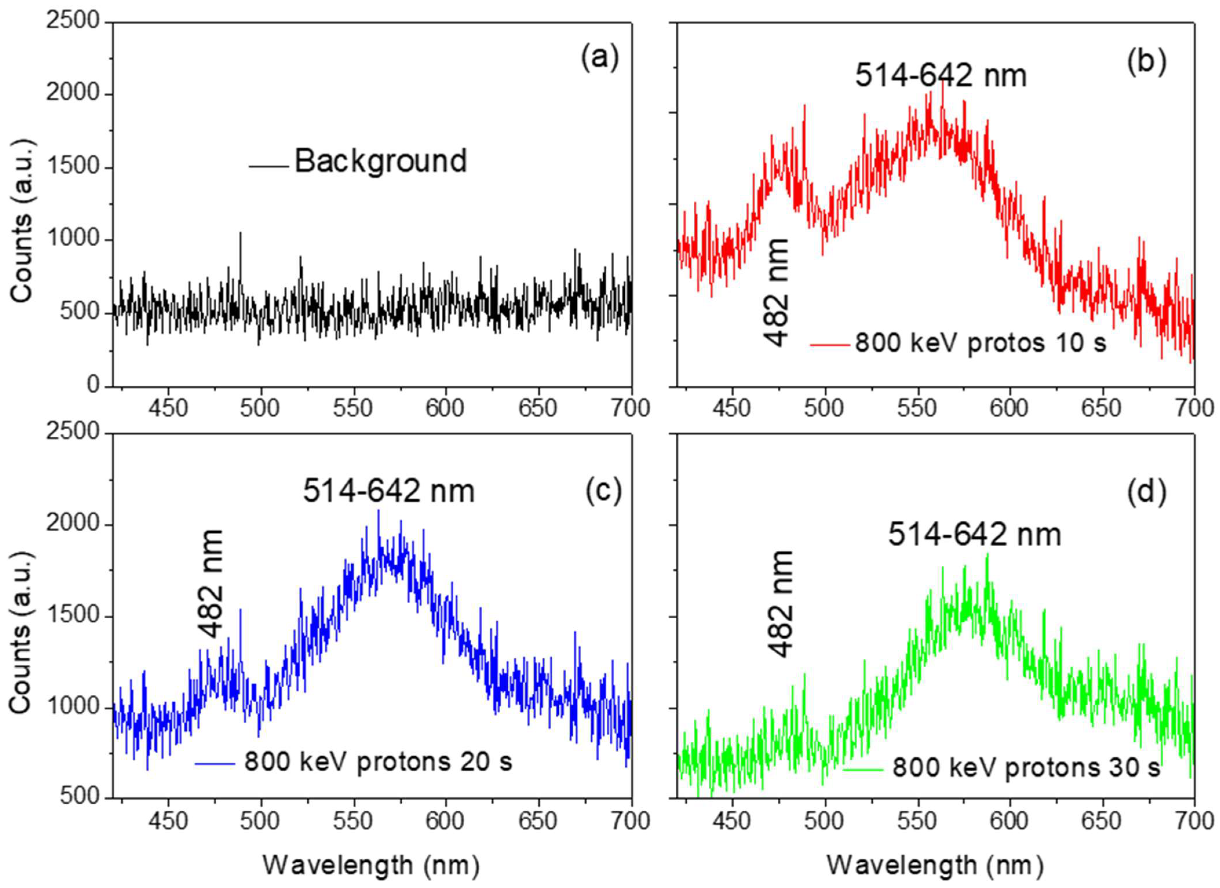
Figure 10 reports the optical spectra obtained by irradiating the Al substrate covered with a thin film of CDs in the same volume as in the previous measurement and irradiated by less energetic protons at an energy of 800 keV.
The optical spectrum recorded when CDs are not deposited on the Al substrate is shown in
Figure 10a. The signal of the emission bands at 480 nm and 514–642 nm is missing, indicating that the luminescence depends on the CDs.
Figure 10b–d shows the effect of the luminescence of CDs deposited on Al substrates when irradiated by protons at 800 keV for 10 s, 20 s, and 30 s to explore the possible dependence on the stopping power.
Figure 11 reports a comparison of the luminescence yield of the CDs versus the irradiation time of 10 s, 20 s, and 30 s for 2 MeV and 800 keV proton ions, respectively. Results prove the dependence of the luminescence yield on the proton energy loss; indeed, increasing the electronic energy loss increases the CDs luminescence, making the materials promising candidates for scintillator detectors.
In the studied case of CD suspension, irradiated by energetic ions, it seems that the observed luminescence could be attributable to molecular electronic transitions [
41]. Typically, these take place when electrons in a molecule are excited from one energy level to a higher energy level that can be determined by UV-Vis spectroscopy. In carbon molecules, the promotion of an electron from a π orbital to an antibonding π* orbital can be induced and is denoted as a π→π* transition involving the aromatic C=C sp
2 carbon bonds, and the C=O chemical bonds or also the
n →
p* transitions, as a result of the lone-pairs vibrating out of plane due to surface level states above the valence band from which the transition with the conduction band may occur [
42]. Carbonyl groups can be generated on the surface of CDs during the carbon nucleation under the laser ablation process [
6,
43].
The use of a continuous laser assists the production of a higher number of CDs, as indicated in ref [
44]. The production of a number of CDs (~ 5.7 × 10
15 particles/cm
3) lower than in a previous experiment [
44] may be ascribable to the use of an unfocused laser beam during the laser ablation process.
The presence of CDs in the suspension produced by laser ablation is confirmed in
Figure 4, which shows the luminescence revealed when both the cuvettes without and with CDs are illuminated by UV light at 365 nm. Moreover, the excitation peaks are visible at 480 nm and 520 nm. The CDs in the suspension affect the luminescence at 480 nm as mentioned in ref. [
45].
The blue color of the CDs suspension suggests a size ranging between 2 nm and 10 nm [
46].
Figure 11 reports, as far as we know, for the first time, the luminescence yield versus the CDs proton irradiation time for two energies, 2.0 MeV and 800 keV. The proton energy loss in the thin film containing the CDs deposited on the Al substrate is different due to the different stopping power, which is higher for 800 keV. In other words, the QY increases with the electronic energy loss of energetic protons.
The reproducibility of the results was observed and monitored by irradiating ten Al substrates covered with CDs under the same conditions. However, in the present study, only three samples irradiated for 10 s, 20 s, and 30 s by 800 keV and 2 MeV proton energies were reported, in
Figure 9 and
Figure 11, to highlight the significance of the results.
The reduction of the luminescence with the irradiation time, observed in
Figure 9 and
Figure 11 at 480 nm, could be induced by the degradation of CDs due to the mechanical interaction between ions and CD structures or by the nucleation of CDs, which increases their size but reduces their luminescence property. The very slight increase in the luminescence at the band between 514 and 642 nm could be ascribed to the presence of CNT in the suspension.
Hamada et al. [
47] predicted that CNTs exhibit high variations in electronic transport, from metallic to semiconducting materials with narrow and moderate band gaps, as a consequence of their diameter and the degree of helical arrangement of the carbon hexagons. The photoluminescence due to recombination of electron–hole pairs at the bandgap is highly predictable if it is assumed that two-thirds of single-walled carbon nanotubes (SWNTs) are direct bandgap semiconductors [
48].
The intrinsic band structure, besides surface reconstructions, dislocations, dopants, dielectric environment, chemical interactions, external electric or magnetic fields, or defects, strongly influences the luminescence of a material [
48]. These factors can deplete or fill existing bands or modify the structure of the band, inducing the shift or the variation of the photoluminescence emission intensities.
The luminescence of the CDs obtained by laser ablation in liquid could be employed for limitless applications such as microelectronics, medicine, biology, or sensors.
The CDs’ luminescence could be used for bioimaging when localized in distinct tissues of cell membranes, which may intensify or quench the luminescence intensity depending on the pH value [
49].
The CDs’ luminescence, depending on the chemical interaction in organisms, could be used to distinguish functional cells from damaged ones or specific molecules like NO
2 or H
2S [
50]. The stability of the substrates coated with a thin layer of CDs was assessed by proton irradiation under the same conditions, three days and three months after their preparation, showing the same behavior over time.
This study is limited to the use of proton ions, whereas other energetic ions could be employed to monitor and compare the fluorescence response of our CDs. However, the work is in progress, and beam time has already been obtained at the Tandetron lab of the Czech Academy of Science.
4. Conclusions
The production, characterization, and application of CDs are animating the scientific community worldwide. In this work, CDs were produced for the first time using a continuous laser; a biocompatible source material as charcoal, and a biocompatible solution as PBS. This choice made it possible to use a low-cost laser system and a well-established technique: laser ablation in liquid. The properties of produced CDs are strictly related to the nature of the charcoal, the composition of the PBS, and the thermal and chemical interactions induced during the laser irradiation.
CDs were produced using a diode laser operating in the visible region, irradiating charcoal immersed in a PBS solution for 180 min. CDs are obtained from photo-thermal and photochemical effects with the ejection of carbon atoms and molecules bonded by van der Waals forces. The measured ablation yield is about 5.7 × 10¹⁵ particles/cm3.
In this study, the luminescence of CDs was revealed by irradiation with UV light at 365 nm wavelength and, for the first time, also using energetic protons at 800 keV and 2 MeV.
The existing literature reports on studies of luminescence induced by X-rays, while we report on luminescence induced by proton ions. In this case, the luminescence depends on the energy loss by protons in the CDs layer, which is proportional to the ion current and their stopping power. It is well established that the photoluminescence of CDs is strictly related to synthesis methods, primary materials, and heteroatom doping as indicated in the KPIs. The revealed photoemission increased from 2 MeV to 800 keV proton energies. This is the first attempt at luminescence induced by energetic proton ions; however, developments concerning the improvement of the CDs concentration and the use of thicker layers of CDs could be promising to promote the emission yield and the evaluation of the ion shift in the luminescence due to the energy loss of protons.
This study could pave the way for the manufacturing of high-sensitivity detectors of ionizing radiation proportional to proton current (i.e., dose), scintillators with higher efficiency, and new materials usable as dosimeters.
The importance of this study lies, besides the original procedure for the CDs manufacturing, in the detection of luminescence under ion irradiation. This makes the produced CDs useful for cell culture treatment for biomedicine applications. The CDs’ luminescence emission due to proton irradiation indicates that a further application can be devoted to the use of the CD thin film as ion detectors for nuclear applications.

 ,
, 


