Abstract
Bipyridyl Ruthenium-decorated Ni-MOFs on multi-walled carbon nanotubes (MWCNT-RuBpy@Ni-MOF) were synthesized. In an alkaline solution, the glucose was electrocatalytically oxidized at +0.5 V vs. Ag/AgCl at the composite interface of MWCNT-RuBpy@Ni-MOF on a glassy carbon electrode. The Ni3+/Ni2+ redox couples in Ni-MOFs played a key role as the active center for the catalytic oxidation of glucose at the electrode, where both RuBpy and MWCNTs enhanced the current responses to glucose. The resulting enzymeless glucose sensor from MWCNT-RuBpy@Ni-MOF exhibited a wide range of linear responses, high sensitivity and selectivity for the determination of glucose.
1. Introduction
The quantitative detection of glucose plays an important role in food science, agricultural science, biological science and other fields [1,2,3,4,5,6]. Since biological oxidases and dehydrogenase for substrates such as lactate, glucose and alcohols have limitations such as a low stability, difficulty in reuse and high costs, people explore various ways to detect these substrates via their direct oxidation. However, under normal circumstances, these substances are not easily directly oxidized. The catalytic activity of some MOFs enables the electrocatalytic oxidation of the target analytes without the need for the enzymes [7,8,9,10,11]. Moreover, the catalytic performance of MOFs can be greatly enhanced by incorporating other materials. The rational design and engineering of MOFs and their composite materials provide new opportunities for the development of various new catalytic sensing strategies and detection mechanisms [12,13,14,15,16,17,18]. On the other hand, the low conductivity and instability of MOFs in aqueous media limit their application in electrochemical processes and sensors [19].
Theoretically, the Ni-H2O system yields a gradual increase in the valence state of Ni from Ni2+ to Ni4+ with increasing potential values. Experimentally, cyclic voltametric tests have been efficiently implemented to observe Ni2+/Ni3+ and Ni3+/Ni4+ electron pairs [20,21]. Indeed, the reduction of high valence Ni4+ to low valence Ni2+ can be achieved by two consecutive single-electron-transfer channels, Ni4+/Ni3+ and Ni3+/Ni2+ [22,23]. The observation of isolated oxidation peaks in nickel-based electrochemistry is very important since the higher valence and smaller radius of the transition metal cation are more oxidatively active [24,25]. The redox reactions of glucose catalyzed by nickel-based materials are generally interpreted as the deprotonation and isomerization of glucose by Ni3+/Ni2+ redox couples. In fact, some glucose sensors have been developed using Ni-based MOFs composites for improving the catalytic performance and catalytic efficiency of the sensors. For example, the Ni2(dihydroxyterephthalic acid) (also known as CPO-27-NiII)-modified glassy carbon electrode exhibited a wide linear range of glucose detection with high sensitivity (~585 μA mM−1 cm−2) and a low detection limit (1.46 μM) [1]. A layer-assembled flower-like Ni-MOF/carbon nanotube composite was used to fabricate the glucose sensor with a sensitivity of 77.7 μA mM−1 cm−2 and a linear range of 20 μM to 4.4 mM [3]. The glucose sensor employing ultrathin Ni-MOF nanoribbons was reported with a sensitivity of 1.542 μA mM−1 cm−2 and a linear range of 1–500 μM [26]. However, in most cases, due to low conductivity and the absence of electron transfer mediators, the sensors based on Ni-MOFs usually have limited sensitivity in the detection of glucose. Exceptionally, Lu and Sun et al. reported that a glucose sensor based on a conductive Ni-MOF material Ni3(HHTP)2 displayed a high sensitivity of 21,744 μA mM−1 cm−2 [27].
Tris(2,2′-bipyridyl) ruthenium dichloride (RuBpy) is an electron transfer mediator with both fluorescent and electrochemical redox properties. Many reports have focused on the immobilization of RuBpy, including the Langmuir–Blodgett technological approach [28,29,30], the self-assembly technique [31,32] and the sol-gel method [33,34,35,36]. The immobilization materials for RuBpy have also been applied to sensing, such as cation-exchange polymers [37,38,39], SiO2 nanoparticles [40,41,42,43], carbon nanotubes [44,45], metal nanoparticles [46] and MOF materials [47]. Among these materials, multi-walled carbon nanotubes (MWCNTs) have excellent electrical conductivity (1.85 × 10³ S cm−1) as a carrier material [48]. Current densities close to 109 A cm−2 have also been reported for MWCNTs [49]. Together with the robust adsorption and mechanical properties of MWCNTs, this makes them strong candidates for microelectronic devices and electrode interconnections in numerous applications.
In this work, the Ni-MOF material was synthesized using p-phthalic acid (PTA) as the ligand. RuBpy was spontaneously adsorbed on the Ni-MOF material to form RuBpy@Ni-MOF. Then, RuBpy@Ni-MOF and MWCNTs were co-suspended in a Nafion solution. The resulting MWCNT-RuBpy@Ni-MOF (Scheme 1) was then loaded on electrodes as an electrocatalyst to construct the enzymeless glucose electrochemical sensor. Both RuBpy as an electron transfer mediator and MWCNTs as a carrier enhanced the catalytic efficiency of the Ni-MOF material for glucose oxidation and thus strengthened the sensor performance.

Scheme 1.
Synthesis of MWCNT-RuBpy@Ni-MOF.
2. Materials and Methods
All experiments and experimental preparations were carried out at ambient conditions at room temperature (22 ± 1 °C), except for those specified. Ni(NO3)2·6H2O and DMF were purchased from Xilong Scientific (Shantou, China). The Tris(2,2′-bipyridyl)ruthenium dichloride was from D&B Biotech (Shanghai, China). MWCNTs, uric acid and L-Cysteine (L-Cys) were purchased from Aladdin (Shanghai, China). The MWCNTs from Aladdin (Product # C139823) contain 95% of multi-walled carbon nanotubes with an average length of 50 μm, whose interior and outer diameters are in the range of 3–5 nm and 8–15 nm, respectively. P-phthalic acid (PTA), Nafion (5%), glucose, fructose, maltose, D-ribose and sucrose were purchased from Macklin Biochem (Shanghai, China). D-lactose was purchased from Yuanye Biotech (Shanghai, China). L-ascorbic acid and urea were obtained from Rhawn Reagents (Shanghai, China). All reagents were used without further purification.
The solvothermal synthesis of Ni-MOFs in DMF has been reported using either Ni (NO3)2 or NiCl2 as the source of Ni2+ with a variety of ligands [1,3,14,50]. In this work, the Ni-MOF material was synthesized using a similar procedure as previously reported [1,3,14,50]. In total, 2.18 g of Ni(NO3)2·6H2O and 0.50 g of PTA were dissolved in 60 mL DMF via stirring, forming into an emerald-green solution. The solution was transferred to a polytetrafluoroethylene-lined reaction kettle and allowed to react at 120 °C for 24 h. Then, it was cooled to room temperature. The reacted mixture was centrifuged at 10,000 rpm for 5 min. The deposit was washed with ethanol and centrifuged five times to remove the excess reactants and residual DMF. The deposit was dried in a vacuum drying oven at 60 °C for 12 h. The dried deposit was ground and, thus, the Ni-MOF material was obtained.
A total of 45 mg of Ni-MOFs was dispersed and suspended in 9 mL of ethanol. A total of 18 mg of RuBpy was dissolved in 9 mL of ethanol. The Ni-MOF suspension and the RuBpy solution were mixed and shaken at 1000 rpm at 4 °C for 10 h to allow RuBpy to be adsorbed on Ni-MOF. The mixture was washed with ethanol and centrifuged at 7000 rpm for 5 min three times. The deposit was dried at room temperature. The dried deposit was ground and, thus, RuBpy@Ni-MOF was obtained.
In total, 0.25 mL of 2 mg/mL of RuBpy@Ni-MOF in 0.05% Nafion aqueous solution was mixed well with 0.25 mL of 1 mg/mL of MWCNTs in 0.05% Nafion aqueous solution until it was well dispersed and ready for use. The glassy carbon electrode (GCE, diameter: 3 mm) was polished until it was subsequently smooth with 1 μm, 0.3 μm and 0.05 μm alumina polishing powder. The GCE surface was then ultrasonically cleaned with 1:3 nitric acid, deionized water and ethanol, respectively. Then, the clean GCE was dried with N2. Then, 5 μL of the prepared suspension of RuBpy@Ni-MOF and MWCNTs in 0.05% Nafion aqueous solution was pipetted onto the GCE surface and allowed to dry at room temperature. Thus, the working electrode MWCNT-RuBpy@Ni-MOF/GCE was obtained. In the absence of MWCNTs, the control electrodes Ni-MOF/GCE and RuBpy@Ni-MOF/GCE were prepared in a similar way.
The three-electrode electrochemical measurements were carried out with a CHI730E electrochemical workstation in 5 mL of 0.1 M NaOH solution, where MWCNT-RuBpy@Ni-MOF/GCE or the control electrode was the working electrode, a Ag/AgCl (3M KCl) electrode was the reference electrode and a platinum wire was the counter electrode. The electrochemical measurements were implemented with cyclic voltammetry and chronoamperometry (current versus time (i-t) curve). For cyclic voltametric tests, the potential range was scanned from 0.0 V to +0.8 V at the scanning rate of 100 mV/s. In i-t tests, the glucose was successively added under constant stirring with the potential set at +0.5 V, except for those specified.
Scanning electron microscopy (SEM) images were acquired by a field emission scanning electron microscope (HT7000, Hitachi SU5000, Tokyo, Japan) operated at 5 kV. Transmission electron microscopy (TEM) images were obtained at a working voltage of 200 kV by a field emission transmission electron microscope (JEM-2100F, Japan Electronics, Tokyo, Japan). X-ray photoelectron spectroscopy (XPS) was measured on an XPS spectrometer (ESCALAB 250Xi, Thermo Electron Corporation, Round Rock, TX, USA).
3. Results and Discussion
The SEM images show the morphologies of Ni-MOFs, RuBpy@Ni-MOF and MWCNT-RuBpy@Ni-MOF (Figure 1). Figure 1a displays that Ni-MOFs had a morphology of aggregated spherical and irregular particles. Figure 1b shows that the morphology of RuBpy@Ni-MOF did not change much but with some fine particles of RuBpy decorated on Ni-MOFs. Figure 1c demonstrates that RuBpy@Ni-MOF particles were embellished and more dispersive on MWCNTs, compared to those aggregates in the absence of MWCNTs (Figure 1a,b). Figure 2a shows the TEM image of Ni-MOFs. The morphology of the Ni-MOF particles shows a spherical shape, and the size is about 100 nm. There are some extra crystals on the surface of RuBpy@Ni-MOF, and thus, it appears much rougher than Ni-MOFs (Figure 2a,b), indicating RuBpy was compounded on Ni-MOFs. Figure 2c shows the TEM image of MWCNT-RuBpy@Ni-MOF. Obviously, MWCNTs were entangled around RuBpy@Ni-MOF. The image with high-angle annular dark-field transmission electron microscopy (HAADF-TEM) and the EDS elemental distribution mappings of O, Ni, N and Ru of RuBpy@Ni-MOF are displayed in Figure 2d–h. The major and characteristic elements, O, Ni, N and Ru, were uniformly distributed with RuBpy@Ni-MOF (Figure 2d–h). The results demonstrate that RuBpy was uniformly distributed all over the Ni-MOF surface.
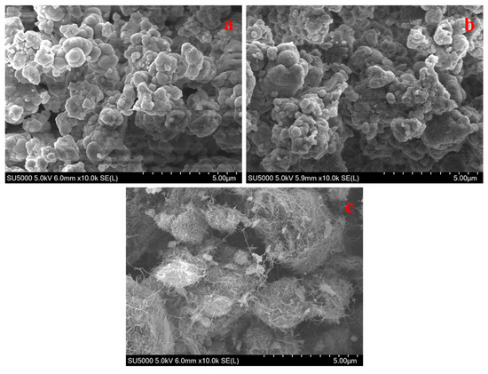
Figure 1.
SEM images of Ni-MOFs (a); RuBpy@Ni-MOF (b); MWCNT-RuBpy@Ni-MOF (c).
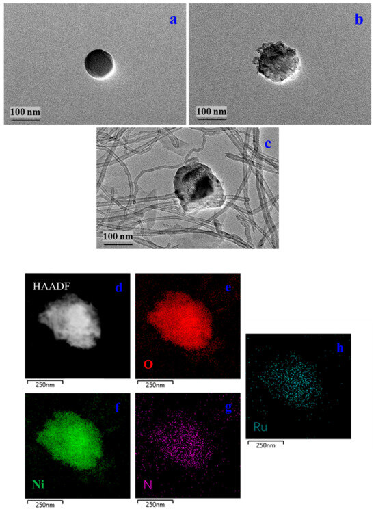
Figure 2.
TEM images of Ni-MOFs (a); RuBpy@Ni-MOF (b); MWCNT-RuBpy@Ni-MOF (c); HAADF-TEM image of RuBpy@Ni-MOF (d); Single-colored EDS elemental dot mappings of O, Ni, N and Ru, respectively (e–h).
XPS tests of RuBpy@Ni-MOF could reveal the surface electronic state and core energy levels of the elements. Figure 3a shows the full spectra of the representative elements Ni, O, N, C and Ru present in RuBpy@Ni-MOF. The binding energies of Ru and C are located in the same region, and the binding energy of C is large, so the characteristic peak of Ru is partially masked by the characteristic peak of C. Figure 3b–d demonstrate the analytical spectra of Ni 2p, Ru 3d and N 1s. Figure 3b illustrates the core energy level spectra of Ni 2p, showing the presence of two states of Ni. In the fine spectrum of Ni 2p, the two peaks observed at 855.9 eV and 873.7 eV belong to Ni 2p3/2 and Ni 2p1/2 of Ni0, respectively, while the peaks of Ni 2p3/2 and Ni 2p1/2 in Ni2+ are located at 860.34 eV and 878.0 eV, respectively. In addition, the other two peaks are the satellite peaks of Ni 2p3/2 and Ni 2p1/2 of Ni2+ with the spin-orbit energy level located at 863.7 eV and 881.2 eV, respectively [51]. Figure 3c demonstrates the analytical spectrum of Ru 3d. The high-resolution XPS spectra of RuBpy@Ni-MOF show Ru 3d has the double peaks Ru 3d5/2 and Ru 3d3/2 located at 284.6 eV and 287.9 eV, respectively, with a spin-orbit splitting energy of 3.3 eV. The Coster–Kronig effect is responsible for the 3d3/2 peak being much wider than the 3d5/2 peak, which is consistent with the report [52]. Figure 3d demonstrates the analytical spectrum of N 1s. There are two characteristic peaks for N 1s, which are C=N-C and N-Ru, located at 400.0 eV and 406.9 eV, respectively [53]. The results demonstrate that RuBpy@Ni-MOF was successfully synthesized.
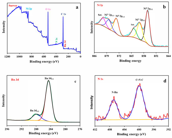
Figure 3.
XPS spectra of RuBpy@Ni-MOF (a), Ni 2p (b), Ru 3d (c), and N 1s (d).
Cyclic voltametric experiments were carried out with GCE, Ni-MOF/GCE, RuBpy@Ni-MOF/GCE and MWCNT-RuBpy@Ni-MOF/GCE in the absence and presence of 1 mM glucose in 0.1 M NaOH. Figure 4 shows the well-defined redox peaks resulting from Ni3+/Ni2+ redox couples of Ni-MOF/GCE, RuBpy@Ni-MOF/GCE and MWCNT-RuBpy@Ni-MOF/GCE. Compared to the bare GCE, the redox peaks were attributed to the Ni2+/Ni3+ redox electron pair [14]. The oxidation peaks of all three electrodes were located around +0.51 V (Figure 4). The reduction peaks of Ni-MOF/GCE and RuBpy@Ni-MOF/GCE were located around +0.33 V, while the reduction peak of MWCNT-RuBpy@Ni-MOF/GCE was located around 0.29 V (Figure 4). Since the baselines of cyclic voltammograms of three modified electrodes were nearly the same as that of the naked GCE during the potential scanning in the direction from the low potential to the high potential prior to the oxidation of Ni2+ to Ni3+, in the absence of glucose, the current increase could result from a reduced resistance of the system upon adding RuBpy and MWCNTs. The peak currents of the Ni3+/Ni2+ redox couples were in the range of 0.5–1.0 mA. This is a large current range for GCE with a diameter of 3 mm. In the presence of glucose, the catalytic currents were observed for all three modified electrodes. The catalytic currents, the differences in the oxidation peak currents in the absence and presence of glucose, were actually increased larger and larger when the working electrode switched from Ni-MOF/GCE to RuBpy@Ni-MOF/GCE and then to MWCNT-RuBpy@Ni-MOF/GCE. For example, at +0.55 V, the differences in the oxidation peak currents in the absence and presence of glucose were about 66.0, 71.0 and 100.1 μA for Ni-MOF/GCE, RuBpy@Ni-MOF/GCE and MWCNT-RuBpy@Ni-MOF/GCE, respectively. The results demonstrate that, besides providing greater conductivity and a larger electrode area, MWCNTs could allow the aggregated RuBpy@Ni-MOF particles to be more dispersive on the electrode (Figure 1c), which could thus expose more active sites for the catalytic oxidation of glucose and accordingly enhance the catalytic currents to some extent. Although the differences in the oxidation peak currents in the absence and presence of glucose seemed as a small fraction of the peak currents of three modified electrodes, such catalytic currents over 60.0 μA were still quite large for 3 mm GCE. MWCNT-RuBpy@Ni-MOF/GCE was thus selected as the working electrode for the rest of this work.
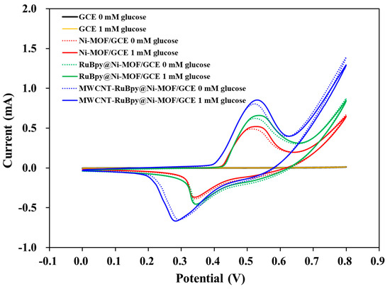
Figure 4.
Cyclic voltammograms of GCE, Ni-MOF/GCE, RuBpy@Ni-MOF/GCE and MWCNT-RuBpy@Ni-MOF/GCE in 0.1 M NaOH in the absence and the presence of 1 mM glucose, respectively. The scanning rate: 100 mV/s.
In 0.1 M NaOH, the specific reaction formula was proposed as the following equation [14]:
Ni(OH)2 + OH− → NiOOH + H2O + e−
2NiOOH + glucose → 2Ni(OH)2 + gluconolactone
During anodic scanning in 0.1 M NaOH, it was proposed that Ni(OH)2 could be generated at the surface of MWCNT-RuBpy@Ni-MOF/GCE. Ni(OH)2 could lose one electron to generate NiOOH in 0.1 M NaOH, as shown in Equation (1). In the presence of 1 mM glucose, NiOOH could oxidize glucose to generate Ni(OH)2 again, thus increasing the anodic peak current, as shown in Equation (2) [54]. The positive shift of the anodic peak indicates the slower kinetics of the reaction, including the oxidized intermediates and the uptake of glucose at the active site [55].
Figure 5a shows cyclic voltammograms of MWCNT-RuBpy@Ni-MOF/GCE at different scan rates in the presence of 1 mM glucose in 0.1 M NaOH. The redox peak currents increased as the scan rate increased, and the oxidation and reduction peak currents (Ia and Ic) were proportional to the square root of the scan rate (Figure 5b). The results demonstrate that the electrocatalytic glucose oxidation process at MWCNT-RuBpy@Ni-MOF/GCE was a typical diffusion-controlled electrochemical reaction [56].
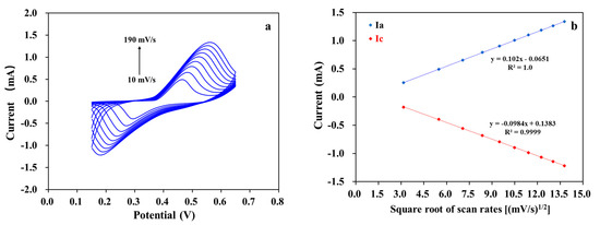
Figure 5.
(a) Cyclic voltammograms of MWCNT-RuBpy@Ni-MOF/GCE with scan rates from 10 mV/s to 190 mV/s in 0.1 M NaOH containing 1 mM glucose; (b) Fitting curve of peak currents vs. square root of scan rates.
The i-t curves were tested using MWCNT-RuBpy@Ni-MOF/GCE at different applied potentials with the step concentrations of 0.5 mM, 1 mM, 1.5 mM, 2 mM and 2.5 mM in the testing solution for glucose (Figure 6a). Overall, at +0.45 V and +0.50 V, the current responses were larger than those at +0.55 V and +0.60 V. And the current response at +0.50 V was slightly higher than that at +0.45 V. At +0.60 V, the increase in the current response was not significant, and the baseline current was much larger than that at +0.45, +0.50, and +0.55 V. Considering that the higher the potential, the greater the number of possible interfering substances, +0.50 V was selected as the optimal working potential for subsequent testing. In order to investigate the selectivity of MWCNT-RuBpy@Ni-MOF/GCE, the potential interferences such as AA, UA, L-Cys, Urea, fructose, lactose, maltose, sucrose and D-ribose were tested under the same conditions as for glucose. In human serum, the concentration of glucose is more than 30 times higher than that of these interferences. The experiments were carried out under continuous stirring in the presence of 0.5 mM glucose and 50 μM interfering substances (Figure 6b). The results demonstrate that the responses to all tested substances were minimal. Therefore, the glucose sensor developed in this work could be practically applied for the determination of glucose in some real samples.
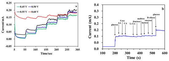
Figure 6.
(a) Amperometric responses of MWCNT-RuBpy@Ni-MOF/GCE to successive additions of glucose at the different potentials in 0.1 M NaOH. The concentration of glucose in the testing solution was 0.5 mM, 1 mM, 1.5 mM, 2 mM and 2.5 mM for each step of glucose addition; (b) Current responses (i-t curve) of MWCNT-RuBpy@Ni-MOF/GCE of 0.5 mM glucose and 50 μM AA, Urea, UA, L-Cys, fructose, lactose, maltose, sucrose and D-ribose, respectively, in 0.1 M NaOH at +0.50 V.
For the calibration plot, the i-t curve was obtained with MWCNT-RuBpy@Ni-MOF/GCE at +0.50 V (Figure 7a). The inset represents the i-t curve for low concentrations of glucose with a minimum concentration of 5 μM. The detection limit of the resulting glucose sensor based on MWCNT-RuBpy@Ni-MOF/GCE was as low as 1.5 μM. The fitting curve of response currents vs. glucose concentrations exhibited that the glucose sensor had a wide linear detection range from 5 μM to 3.5 mM, spanning three orders of magnitude (Figure 7b). The R2 values were 0.9966, 0.9977 and 0.9959 for the linear ranges of 5 μM to 50 μM (upper-left inset of Figure 7b), 50 μM to 0.5 mM (lower-right inset of Figure 7b) and 5 mM to 3.5 mM of glucose concentrations, respectively. When taking the entire linear range from 5 μM to 3.5 mM of glucose into account, its R2 value was 0.9967 (Figure 7b). Based on the slope of 0.103 μA·μM−1 and the GCE surface area (0.07 cm2), the sensitivity of the glucose sensor was calculated as 1471.43 μA·mM−1·cm−2.
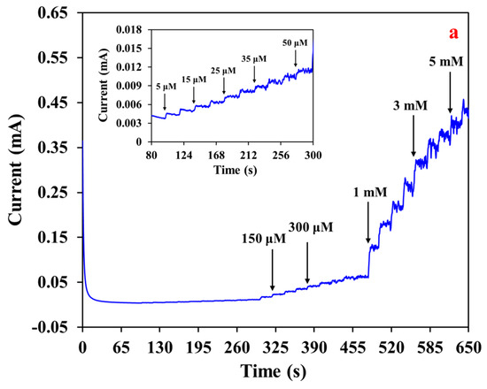
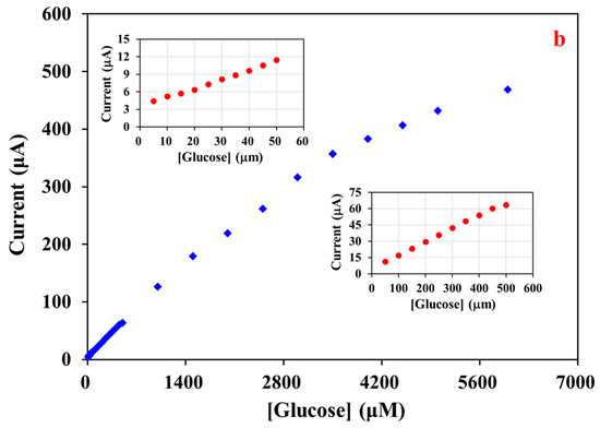
Figure 7.
(a) Amperometric responses of MWCNT-RuBpy@Ni-MOF/GCE to successive additions of glucose at +0.50 V in a 0.1 M NaOH. Inset: i-t curve of low concentrations of glucose; (b) Calibration plot of glucose in a wide linear range.
The response stability of MWCNT-RuBpy@Ni-MOF/GCE was evaluated by continuously recording the i-t curve in the presence of 1 mM glucose (Figure 8a). The current signal was measured over 2500 s. Taking the increment of the current response at the time of addition of glucose at 100 s as 100%, the current signal was retained by 99.65% after 1000 s, 95.24% after a 1500 s scan and 92.51% after 2500 s, respectively. The results show that MWCNT-RuBpy@Ni-MOF/GCE was relatively stable in detecting glucose. The response stability of MWCNT-RuBpy@Ni-MOF in the detection of glucose was also characterized by multiple assays with the same sensor in the presence of 1 mM glucose (Figure 8b). The response stability was retained by 99.52% after 5 assays and by 91.47% after 30 assays, respectively. The data demonstrate that MWCNT-RuBpy@Ni-MOF/GCE had an outstanding response stability.
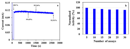
Figure 8.
(a) Amperometric response stability of MWCNT-RuBpy@Ni-MOF/GCE; (b) Stability of MWCNT-RuBpy@Ni-MOF after multiple assays. [Glucose]: 1 mM. Working solution: 0.1 M NaOH. Working potential: +0.50 V.
The reproducibility of multiple sensors was tested with six MWCNT-RuBpy@Ni-MOF/GCEs prepared from the same preparing process (Figure 9). For the response of 0.5 mM glucose, the relative standard deviation (RSD) of 1.11% was acquired with the time window 800 to 1000 s for the six sensors (Figure 9a and the inset). Figure 9b shows the response reproducibility by recording the i-t curves of six sensors under successive additions of glucose. For the glucose concentration steps from 0.1 to 0.8 mM, the RSD of 7.21–15.75% was obtained with the current signal at 10 s of each step plateau for the six sensors (Figure 9b). The results demonstrate that the constructed enzymeless glucose sensors had good performance reproducibility.

Figure 9.
(a) Amperometric responses of six MWCNT-RuBpy@Ni-MOF/GCEs in the presence of 0.5 mM glucose at +0.50 V in 0.1 M NaOH; (b) i-t curves of six MWCNT-RuBpy@Ni-MOF/GCEs at +0.50 V in 0.1 M NaOH. The glucose concentration in the testing solution for each step was 0.1, 0.2, 0.3, 0.4, 0.5, 0.6, 0.7 and 0.8 mM, respectively.
The chronoamperograms (i-t curves) were measured with different concentrations of glucose at +0.5 V to further evaluate the electrocatalytic kinetics of glucose oxidation at MWCNT-RuBpy@Ni-MOF/GCE (Figure 10a). The electrocatalytic kinetics were studied for the initial rate of current responses in the time window at the very beginning of the development of the i-t curve from 0.4 to 1.3 s (Figure 10a). Figure 10b shows that the linear curve of Icat/I0 vs. t1/2 originated from the chronoamperogram at 0.0 mM and 1.0 mM glucose. Therefore, the catalytic rate constant (kcat) for glucose oxidation can be calculated using the following equation [14]:
where Icat and I0 are the currents in the presence and absence of glucose, respectively; C is the concentration of glucose; and t is the time in s. When [glucose] was 1 mM, based on the slope of the plot of Icat/I0 vs. t1/2, , indicating that the composite electrode interface of MWCNT-RuBpy@Ni-MOF/GCE had good electrocatalytic activity for glucose oxidation.
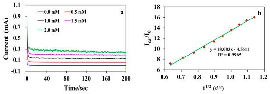
Figure 10.
(a) Chronoamperograms of MWCNT-RuBpy@Ni-MOF/GCE in the presence of various concentrations of glucose in 0.1 M NaOH; (b) The plot of Icat/I0 vs. t1/2, derived from the data of the chronoamperogram for 1 mM glucose.
The comparison of the performances of the enzymeless glucose sensors based on Ni-based materials including Ni-MOFs is in Table 1. Compared to the enzymeless electrochemical glucose sensors based on other Ni-based composite materials, MWCNT-RuBpy@Ni-MOF/GCE exhibited high sensitivity and a wide linear range of responses. However, the catalytic current in the presence of glucose only accounted for a small fraction of the oxidation peak currents of the composite material-modified electrodes in the absence of glucose, implying that the ratio of Ni-MOF compositing with RuBpy and MWCNTs could be optimized to reduce the base current. The detection limit could thus be further improved compared to that of other enzymeless glucose sensors reported (Table 1). The actual measurements of glucose in a honey product from the local market with MWCNT-RuBpy@Ni-MOF/GCE was studied by the recovery experiment. The calibration plot based on the i-t curve (Figure 7) with the successive addition of glucose was used to determine the glucose concentration in honey samples. Using the same procedure for the calibration plot displayed in Figure 7, the diluted honey sample was first added in the testing solution, and subsequently, three glucose solutions were successively added under stirring, and the current responses were continuously recorded. Each current value was calculated based on the calibration plot. The experimental results are summarized in Table 2. The sample recoveries were in the range of 100.26–102.14%, which demonstrated the potential application prospects of MWCNT-RuBpy@Ni-MOF/GCE in the analysis of practical samples.

Table 1.
Comparison of the performances of the electrochemical glucose sensors based on MWCNT-RuBpy@Ni-MOF and other Ni-based materials in the electrolyte 0.1 M NaOH.

Table 2.
Determination of glucose in the testing solution for honey samples (n = 3).
4. Conclusions
In summary, the composite material of MWCNT-RuBpy@Ni-MOF was prepared and successfully applied to glucose oxidation and enzymeless electrochemical glucose sensing. In the alkaline condition, the catalytic oxidation peak of the redox pair of Ni2+/Ni3+ from Ni-MOFs occurred around the working potential of +0.50 V (vs. Ag/AgCl). The catalytic current was enhanced by decorating the Ni-MOF material with the electron transfer mediator RuBpy, and the catalytic current was further enhanced after compositing with MWCNTs. Besides providing greater conductivity and a larger electrode area, MWCNTs could allow the aggregated RuBpy@Ni-MOF particles to be more dispersive on the electrode and thus expose more catalytic active sites for the oxidation of glucose and accordingly enhance the catalytic currents to some extent. The resulting enzymeless sensor based on MWCNT-RuBpy@Ni-MOF had an excellent performance in detecting glucose, with a wide range of linear responses, a low detection limit, high sensitivity and good selectivity. The sensor also had good stability and reproducibility and was successfully applied for the glucose measurement of the honey product. The results demonstrate that Ni-MOFs served as the catalytic and active center, while RuBpy and MWCNTs also promoted the glucose oxidation at the electrode and thus the sensor performance.
Author Contributions
Conceptualization, C.L. (Chenghong Lei) and C.L. (Chang Liu); methodology, Y.Z. and C.L. (Chang Liu); validation, Y.Z. and R.Y.; formal analysis, Y.Z., R.Y. and C.L. (Chang Liu); investi-gation, Y.Z., R.Y. and C.L. (Chang Liu); resources, C.L. (Chenghong Lei); data curation, Y.Z., R.Y. and C.L. (Chang Liu); writing—original draft preparation, C.L. (Chenghong Lei), Y.Z. and C.L. (Chang Liu); writing—review and editing, C.L. (Chenghong Lei), Y.Z. and R.Y.; supervision, C.L. (Chenghong Lei); project administration, C.L. (Chenghong Lei); funding acquisition, C.L. (Chenghong Lei). All authors have read and agreed to the published version of the manuscript.
Funding
This work was funded by the National Natural Science Foundation of China (Grant number 32060521) and the Natural Science Foundation of Guangxi, China (Grant numbers AD22035016 and 2020GXNSFDA297023).
Institutional Review Board Statement
Not applicable.
Informed Consent Statement
Not applicable.
Data Availability Statement
The raw data supporting the conclusions of this article will be made available by the authors on request.
Conflicts of Interest
The authors report no conflicts of interest.
References
- Lopa, N.S.; Rahman, M.; Ahmed, F.; Sutradhar, S.C.; Ryu, T.; Kim, W. A Ni-based redox-active metal-organic framework for sensitive and non-enzymatic detection of glucose. J. Electroanal. Chem. 2018, 822, 43–49. [Google Scholar] [CrossRef]
- Chen, C.; Zhong, Y.; Cheng, S.; Huanga, Y.; Li, T.; Shi, T.; Liao, G.; Tang, Z. In Situ Fabrication of Porous Nanostructures Derived from Bimetal-Organic Frameworks for Highly Sensitive Non-Enzymatic Glucose Sensors. J. Electrochem. Soc. 2020, 167, 027531. [Google Scholar] [CrossRef]
- Wang, F.; Chen, X.; Chen, L.; Yang, J.; Wang, Q. High-performance non-enzymatic glucose sensor by hierarchical flower-like nickel(II)-based MOF/carbon nanotubes composite. Mater. Sci. Eng. C 2019, 96, 41–50. [Google Scholar] [CrossRef]
- Zheng, W.; Liu, Y.; Yang, P.; Chen, Y.; Tao, J.; Hu, J.; Zhao, P. Carbon nanohorns enhanced electrochemical properties of Cu-based metal organic framework for ultrasensitive serum glucose sensing. J. Electroanal. Chem. 2020, 862, 114018. [Google Scholar] [CrossRef]
- Wang, H.-B.; Zhang, H.-D.; Chen, Y.; Li, Y.; Gan, T. H2O2-mediated fluorescence quenching of double-stranded DNA templated copper nanoparticles for label-free and sensitive detection of glucose. RSC Adv. 2015, 5, 77906–77912. [Google Scholar] [CrossRef]
- Wang, H.-B.; Chen, Y.; Li, N.; Liu, Y.-M. A fluorescent glucose bioassay based on the hydrogen peroxide-induced decomposition of a quencher system composed of MnO2 nanosheets and copper nanoclusters. Microchim. Acta 2017, 184, 515–523. [Google Scholar] [CrossRef]
- Kreno, L.E.; Leong, K.; Farha, O.K.; Allendorf, M.; Van Duyne, R.P.; Hupp, J.T. Metal–Organic Framework Materials as Chemical Sensors. Chem. Rev. 2012, 112, 1105–1125. [Google Scholar] [CrossRef]
- Lustig, W.P.; Mukherjee, S.; Rudd, N.D.; Desai, A.V.; Li, J.; Ghosh, S.K. Metal–organic frameworks: Functional luminescent and photonic materials for sensing applications. Chem. Soc. Rev. 2017, 46, 3242–3285. [Google Scholar] [CrossRef]
- Yang, Q.; Xu, Q.; Jiang, H.-L. Metal–organic frameworks meet metal nanoparticles: Synergistic effect for enhanced catalysis. Chem. Soc. Rev. 2017, 46, 4774–4808. [Google Scholar] [CrossRef]
- Jiao, L.; Wang, Y.; Jiang, H.-L.; Xu, Q. Metal–Organic Frameworks as Platforms for Catalytic Applications. Adv. Mater. 2018, 30, 1703663. [Google Scholar] [CrossRef]
- Dhakshinamoorthy, A.; Li, Z.; Garcia, H. Catalysis and photocatalysis by metal organic frameworks. Chem. Soc. Rev. 2018, 47, 8134–8172. [Google Scholar] [CrossRef]
- McKeithan, C.R.; Mayers, J.M.; Wojtas, L.; Larsen, R.W. Photophysical studies of Ru(II)tris(2,2′-bipyridine) encapsulated within the ZnHKUST-1 metal organic framework. Inorg. Chim. Acta 2018, 483, 1–5. [Google Scholar] [CrossRef]
- Jin, X.; Li, G.; Xu, T.; Su, L.; Yan, D.; Zhang, X. Ruthenium-based Conjugated Polymer and Metal-organic Framework Nanocomposites for Glucose Sensing. Electroanalysis 2021, 33, 1902–1910. [Google Scholar] [CrossRef]
- Chen, J.; Yin, H.; Zhou, J.; Wang, L.; Gong, J.; Ji, Z.; Nie, Q. Efficient Nonenzymatic Sensors Based on Ni-MOF Microspheres Decorated with Au Nanoparticles for Glucose Detection. J. Electron. Mater. 2020, 49, 4754–4763. [Google Scholar] [CrossRef]
- Abbasi, A.R.; Yousefshahi, M.; Daasbjerg, K. Non-enzymatic Electroanalytical Sensing of Glucose Based on Nano Nickel-Coordination Polymers-Modified Glassy Carbon Electrode. J. Inorg. Organomet. Polym. Mater. 2020, 30, 2027–2038. [Google Scholar] [CrossRef]
- Li, L.-X.; He, S.; Zeng, S.; Chen, W.-T.; Ye, J.-W.; Zhou, H.-L.; Huang, X.-C. Equipping carbon dots in a defect-containing MOF via self-carbonization for explosive sensing. J. Mater. Chem. C 2022, 11, 321–328. [Google Scholar] [CrossRef]
- Elizbit Liaqat, U.; Hussain, Z.; Baig, M.M.; Khan, M.A.; Arif, D. Preparation of porous ZIF-67 network interconnected by MWCNTs and decorated with Ag nanoparticles for improved non-enzymatic electrochemical glucose sensing. J. Korean Ceram. Soc. 2021, 58, 598–605. [Google Scholar] [CrossRef]
- Wen, Y.; Meng, W.; Li, C.; Dai, L.; He, Z.; Wang, L.; Li, M.; Zhu, J. Enhanced glucose sensing based on a novel composite CoII-MOF/Acb modified electrode. Dalton Trans. 2018, 47, 3872–3879. [Google Scholar] [CrossRef]
- Li, W.-H.; Lv, J.; Li, Q.; Xie, J.; Ogiwara, N.; Huang, Y.; Jiang, H.; Kitagawa, H.; Xu, G.; Wang, Y. Conductive metal–organic framework nanowire arrays for electrocatalytic oxygen evolution. J. Mater. Chem. A 2019, 7, 10431–10438. [Google Scholar] [CrossRef]
- Lennon, S.J.; Robinson, F.P.A. The experimental determination of potential-pH diagrams for the Ni-H2O and low alloy steel-H2O systems. Corros. Sci. 1986, 26, 995–1007. [Google Scholar] [CrossRef]
- Camasso, N.M.; Sanford, M.S. Design, synthesis, and carbon-heteroatom coupling reactions of organometallic nickel(IV) complexes. Science 2015, 347, 1218–1220. [Google Scholar] [CrossRef]
- Leem, Y.J.; Cho, K.; Oh, K.H.; Han, S.-H.; Nam, K.M.; Chang, J. A self-assembled Ni(cyclam)-BTC network on ITO for an oxygen evolution catalyst in alkaline solution. Chem. Commun. 2017, 53, 3454–3457. [Google Scholar] [CrossRef]
- Rahmanifar, M.S.; Hesari, H.; Noori, A.; Masoomi, M.Y.; Morsali, A.; Mousavi, M.F. A dual Ni/Co-MOF-reduced graphene oxide nanocomposite as a high performance supercapacitor electrode material. Electrochim. Acta 2018, 275, 76–86. [Google Scholar] [CrossRef]
- Gao, M.; Sheng, W.; Zhuang, Z.; Fang, Q.; Gu, S.; Jiang, J.; Yan, Y. Efficient Water Oxidation Using Nanostructured α-Nickel-Hydroxide as an Electrocatalyst. J. Am. Chem. Soc. 2014, 136, 7077–7084. [Google Scholar] [CrossRef] [PubMed]
- Bediako, D.K.; Lassalle-Kaiser, B.; Surendranath, Y.; Yano, J.; Yachandra, V.K.; Nocera, D.G. Structure–Activity Correlations in a Nickel–Borate Oxygen Evolution Catalyst. J. Am. Chem. Soc. 2012, 134, 6801–6809. [Google Scholar] [CrossRef] [PubMed]
- Xiao, X.; Zheng, S.; Li, X.; Zhang, G.; Guo, X.; Xue, H.; Pang, H. Facile synthesis of ultrathin Ni-MOF nanobelts for high-efficiency determination of glucose in human serum. J. Mater. Chem. B 2017, 5, 5234–5239. [Google Scholar] [CrossRef] [PubMed]
- Qiao, Y.; Liu, Q.; Lu, S.; Chen, G.; Gao, S.; Lu, W.; Sun, X. High-performance non-enzymatic glucose detection: Using a conductive Ni-MOF as an electrocatalyst. J. Mater. Chem. B 2020, 8, 5411–5415. [Google Scholar] [CrossRef] [PubMed]
- Zhang, X.; Bard, A.J. Electrogenerated chemiluminescent emission from an organized (L-B) monolayer of a tris(2,2′-bipyridine)ruthenium(2+)-based surfactant on semiconductor and metal electrodes. J. Phys. Chem. 1988, 92, 5566–5569. [Google Scholar] [CrossRef]
- Miller, C.J.; McCord, P.; Bard, A.J. Study of Langmuir monolayers of ruthenium complexes and their aggregation by electrogenerated chemiluminescence. Langmuir 1991, 7, 2781–2787. [Google Scholar] [CrossRef]
- Zholudov, Y.; Snizhko, D.; Kukoba, A.; Bilash, H.; Rozhitskii, M. Aqueous electrochemiluminescence of polycyclic aromatic hydrocarbons immobilized into Langmuir–Blodgett film at the electrode. Electrochim. Acta 2008, 54, 360–363. [Google Scholar] [CrossRef]
- Sato, Y.; Uosaki, K. Electrochemical and electrogenerated chemiluminescence properties of tris(2,2′-bipyridine)ruthenium(II)-tridecanethiol derivative on ITO and gold electrodes. J. Electroanal. Chem. 1995, 384, 57–66. [Google Scholar] [CrossRef]
- Obeng, Y.S.; Bard, A.J. Electrogenerated chemiluminescence. 53. Electrochemistry and emission from adsorbed monolayers of a tris(bipyridyl)ruthenium(II)-based surfactant on gold and tin oxide electrodes. Langmuir 1991, 7, 195–201. [Google Scholar] [CrossRef]
- Collinson, M.M.; Novak, B.; Martin, S.A.; Taussig, J.S. Electrochemiluminescence of Ruthenium(II) Tris(bipyridine) Encapsulated in Sol−Gel Glasses. Anal. Chem. 2000, 72, 2914–2918. [Google Scholar] [CrossRef]
- Sykora, M.; Meyer, T.J. Electrogenerated Chemiluminescence in SiO2 Sol−Gel Polymer Composites. Chem. Mater. 1999, 11, 1186–1189. [Google Scholar] [CrossRef]
- Matsui, K.; Momose, F. Luminescence Properties of Tris(2,2′-bipyridine)ruthenium(II) in Sol−Gel Systems of SiO2. Chem. Mater. 1997, 9, 2588–2591. [Google Scholar] [CrossRef]
- Choi, H.N.; Cho, S.-H.; Lee, W.-Y. Electrogenerated Chemiluminescence from Tris(2,2′-bipyridyl)ruthenium(II) Immobilized in Titania−Perfluorosulfonated Ionomer Composite Films. Anal. Chem. 2003, 75, 4250–4256. [Google Scholar] [CrossRef]
- Lin, Z.; Chen, G. Determination of carbamates in nature water based on the enhancement of electrochemiluminescent of Ru(bpy)32+ at the multi-wall carbon nanotube-modified electrode. Talanta 2006, 70, 111–115. [Google Scholar] [CrossRef]
- Hun, X.; Zhang, Z. Electrogenerated chemiluminescence sensor for metoclopramide determination based on Ru(bpy)32+-doped silica nanoparticles dispersed in Nafion on glassy carbon electrode. J. Pharm. Biomed. Anal. 2008, 47, 670–676. [Google Scholar] [CrossRef]
- Martin, A.F.; Nieman, T.A. Chemiluminescence biosensors using tris(2,2′-bipyridyl)ruthenium(II) and dehydrogenases immobilized in cation exchange polymers. Biosens. Bioelectron. 1997, 12, 479–489. [Google Scholar] [CrossRef]
- Zhao, C.-Z.; Egashira, N.; Kurauchi, Y.; Ohga, K. Electrochemiluminescence Sensor Having a Pt Electrode Coated with a Ru(bpy)32+-Modified Chitosan/Silica Gel Membrane. Anal. Sci. 1998, 14, 439–441. [Google Scholar] [CrossRef][Green Version]
- Wang, H.; Xu, G.; Dong, S. Electrochemiluminescence of tris(2,2′-bipyridine)ruthenium(II) immobilized in poly(p-styrenesulfonate)–silica–Triton X-100 composite thin-films. Analyst 2001, 126, 1095–1099. [Google Scholar] [CrossRef]
- Zhang, L.; Wang, F.; Dong, S. Layer-by-layer assembly of functional silica and Au nanoparticles for fabricating electrogenerated chemiluminescence sensor. Electrochim. Acta 2008, 53, 6423–6427. [Google Scholar] [CrossRef]
- Lee, J.-K.; Lee, S.-H.; Kim, M.; Kim, H.; Kim, D.-H.; Lee, W.-Y. Organosilicate thin film containing Ru(bpy)32+ for an electrogenerated chemiluminescence (ECL) sensor. Chem. Commun. 2003, 1602–1603. [Google Scholar] [CrossRef]
- Li, J.; Xu, Y.; Wei, H.; Huo, T.; Wang, E. Electrochemiluminescence Sensor Based on Partial Sulfonation of Polystyrene with Carbon Nanotubes. Anal. Chem. 2007, 79, 5439–5443. [Google Scholar] [CrossRef]
- Guo, Z.; Dong, S. Electrogenerated Chemiluminescence from Ru(Bpy)32+ Ion-Exchanged in Carbon Nanotube/Perfluorosulfonated Ionomer Composite Films. Anal. Chem. 2004, 76, 2683–2688. [Google Scholar] [CrossRef]
- Kang, C.H.; Choi, Y.-B.; Kim, H.-H.; Choi, H.N.; Lee, W.-Y. Electrogenerated Chemiluminescence Sensor Based on a Self-Assembled Monolayer of Ruthenium(II)-bis(2,2′-bipyridyl)(aminopropyl imidazole) on Gold Deposited Screen Printed Electrode. Electroanalysis 2011, 23, 2131–2138. [Google Scholar] [CrossRef]
- Xu, X.; Li, H.; Xu, Z. Multifunctional luminescent switch based on a porous PL-MOF for sensitivity recognition of HCl, trace water and lead ion. Chem. Eng. J. 2022, 436, 135028. [Google Scholar] [CrossRef]
- Ando, Y.; Zhao, X.; Shimoyama, H.; Sakai, G.; Kaneto, K. Physical properties of multiwalled carbon nanotubes. Int. J. Inorg. Mater. 1999, 1, 77–82. [Google Scholar] [CrossRef]
- Wei, B.Q.; Vajtai, R.; Ajayan, P.M. Reliability and current carrying capacity of carbon nanotubes. Appl. Phys. Lett. 2001, 79, 1172–1174. [Google Scholar] [CrossRef]
- Zeraati, M.; Alizadeh, V.; Kazemzadeh, P.; Safinejad, M.; Kazemian, H.; Sargazi, G. A new nickel metal organic framework (Ni-MOF) porous nanostructure as a potential novel electrochemical sensor for detecting glucose. J. Porous Mater. 2022, 29, 257–267. [Google Scholar] [CrossRef]
- Ma, X.; Tang, K.-l.; Yang, M.; Shi, W.; Zhao, W. Metal–organic framework-derived yolk–shell hollow Ni/NiO@C microspheres for bifunctional non-enzymatic glucose and hydrogen peroxide biosensors. J. Mater. Sci. 2021, 56, 442–456. [Google Scholar] [CrossRef]
- Morgan, D.J. Resolving ruthenium: XPS studies of common ruthenium materials. Surf. Interface Anal. 2015, 47, 1072–1079. [Google Scholar] [CrossRef]
- Al-Hinaai, M.; Khudaish, E.A. Electrochemical Construction of a Polymer-Metal Complex Surface Network for Selective Determination of Dopamine in Blood Serum. Anal. Lett. 2022, 55, 1249–1268. [Google Scholar] [CrossRef]
- Ren, Z.; Mao, H.; Luo, H.; Liu, Y. Glucose sensor based on porous Ni by using a graphene bottom layer combined with a Ni middle layer. Carbon 2019, 149, 609–617. [Google Scholar] [CrossRef]
- Cao, M.; Wang, H.; Ji, S.; Zhao, Q.; Pollet, B.G.; Wang, R. Hollow core-shell structured Cu2O@Cu1.8S spheres as novel electrode for enzyme free glucose sensing. Mater. Sci. Eng. C 2019, 95, 174–182. [Google Scholar] [CrossRef]
- Li, G.; Chen, D.; Chen, Y.; Dong, L. MOF Ni-BTC Derived Ni/C/Graphene Composite for Highly Sensitive Non-Enzymatic Electrochemical Glucose Detection. ECS J. Solid State Sci. Technol. 2020, 9, 121014. [Google Scholar] [CrossRef]
- Jia, H.; Shang, N.; Feng, Y.; Ye, H.; Zhao, J.; Wang, H.; Wang, C.; Zhang, Y. Facile preparation of Ni nanoparticle embedded on mesoporous carbon nanorods for non-enzymatic glucose detection. J. Colloid Interface Sci. 2021, 583, 310–320. [Google Scholar] [CrossRef]
- Chen, J.; Yin, H.; Zhou, J.; Wang, L.; Ji, Z.; Zheng, Y.; Nie, Q. Hybrid Ni3N-nitrogen-doped carbon microspheres (Ni3N@C) in situ derived from Ni-MOFs as sensitive non-enzymatic glucose sensors. Mater. Technol. 2021, 36, 286–295. [Google Scholar] [CrossRef]
- Li, G.; Xie, G.; Chen, D.; Gong, C.; Chen, X.; Zhang, Q.; Pang, B.; Zhang, Y.; Li, C.; Hu, J.; et al. Facile synthesis of bamboo-like Ni3S2@NCNT as efficient and stable electrocatalysts for non-enzymatic glucose detection. Appl. Surf. Sci. 2022, 585, 152683. [Google Scholar] [CrossRef]
- Asadian, E.; Shahrokhian, S.; Iraji Zad, A. Highly sensitive nonenzymetic glucose sensing platform based on MOF-derived NiCo LDH nanosheets/graphene nanoribbons composite. J. Electroanal. Chem. 2018, 808, 114–123. [Google Scholar] [CrossRef]
Disclaimer/Publisher’s Note: The statements, opinions and data contained in all publications are solely those of the individual author(s) and contributor(s) and not of MDPI and/or the editor(s). MDPI and/or the editor(s) disclaim responsibility for any injury to people or property resulting from any ideas, methods, instructions or products referred to in the content. |
© 2024 by the authors. Licensee MDPI, Basel, Switzerland. This article is an open access article distributed under the terms and conditions of the Creative Commons Attribution (CC BY) license (https://creativecommons.org/licenses/by/4.0/).