Abstract
Electrolyte-gated organic field-effect transistors (EGOFETs) is a popular platform for numerous sensing and biosensing applications in aqueous media. In this work, the variation of electrical characteristics of EGOFETs based on small-molecule organic semiconductor C8-BTBT and polystyrene blend in water solutions at different pH values was investigated. A positive shift of the threshold voltage with near-Nernstian pH sensitivity was demonstrated in the pH range from 4.9 to 2.8, while no measurable pH dependence in the range from 4.9 to 8.6 pH was registered. These results indicate chemical doping of the molecules of organic semiconductors by protons from the electrolyte in the acidic region. In order to check the applicability of the EGOFETs in a flow mode, a flow chamber was designed and assembled. The preliminary results obtained in the flow mode measurements showed a fast response to pH variation.
1. Introduction
Electrolyte-gated organic field-effect transistors (EGOFETs) are electronic devices containing organic semiconductors in water solutions [1,2,3,4]. During the last decade, they found various applications, the most actively growing of which are biosensors due to the ultra-high sensitivity of the EGOFETs resulting in the attomolar limit of detection in some cases [2,5,6]. Such a simple, inexpensive and precise sensing device could be extremely helpful in many cases, including early diagnostics of the globally spread COVID-19 pandemic [7,8,9] or for detection of many other dangerous diseases in the regions having no easy access to expensive laboratory tests. Among the other possible applications of EGOFETs are artificial synapsis [10,11,12,13] and memory devices [14].
EGOFETs are three-electrode electronic devices with an organic semiconductor (OSC) layer. The conductivity of the active channel of OSC between the source and drain electrodes can be adjusted over a wide range by a small change in the gate electrode voltage. The hallmark of EGOFETs is using an electrolyte solution as a gating medium that connects the gate electrode with the OSC conducting channel [15]. The gate voltage applied to the electrolyte in the EGOFET leads to the formation of two electric double layers (EDL, the first—on the interface between the gate electrode and electrolyte—and the second—on the interface between OSC and electrolyte) that represent a capacitor with high specific capacitance (up to tens of µF cm−2), which is several orders of magnitude higher than the specific capacitance of typical organic field-effect transistors (OFETs) [16]. It allows using EGOFETs at very low voltages (less than 0.5 V) that are favorable for biosensing applications in water solutions. The appearance of polar analyte molecules in the electrolyte influences the capacitance of the EGOFET, which leads to the change of one or several electrical parameters. To make the device specific for a particular molecule, a layer of biological recognition elements is usually applied to the gate or the organic semiconductor surface [2,17].
One of the problems that face biosensor devices is non-specific interaction between the particles in solution and with the device interfaces [18]. To date, a notable amount of methods exist to remove the non-specific adsorption of proteins or other biological molecules on the sensing surface [19]. However, the electrical parameters of the EGOFET could also be influenced by interactions with inorganic ions, an excess of hydroxyls, or protons that are always present in biological solutions [20]. Therefore, the aim of this work was to take a closer look at the interaction of small-molecule OSC layer with protons in water solutions because a lot of practical applications of EGOFET sensors involve operation in electrolytes with varying in a broad range of acidity, for instance, physiological solutions such as urine or sweat [21,22,23] as well as wastewater [24,25]. As analyte molecules, protons lead to some challenges associated with their small size and participation in redox reactions that may occur at the OSC—electrolyte interface. Furthermore, protons could also penetrate into the OSC volume of EGOFETs and charge the substrate [26,27]. Moreover, quick protons migration can cause gate voltage screening [28] or contribute to the leakage current [16]. The particular goal of this work was to investigate the influence of acidity on figures of merit of small-molecule organic semiconductor EGOFETs to specify possible limitations for applications of such devices. Finally, we designed and developed a flow chamber to test the EGOFET devices in close-to-real application conditions.
2. Materials and Methods
2.1. Materials
2,7-dioctyl [1]benzothieno[3,2-b]benzothiophene (C8-BTBT) was synthesized according to the method described previously [29]. Organic solvents (toluene, isopropanol) were purchased from Acros Organics (Thermo Fisher Scientific, Geel, Belgium). Polystyrene (PS) Mw = 280,000 was purchased from Sigma-Aldrich and used as received. Ultrapure deionized water with a resistance of 18.2 MΩ was obtained using an Akvilon deionizer D-301 (Akvilon, Moscow, Russia). NaCl, NaOH, and HCl solutions were obtained from Acros Organics. Poly(dimethylsiloxane) (PDMS) reservoir was produced using Ecoflex 0-50 rubber obtained from Smooth-On, Inc., (Macungie, PA, USA).
2.2. Fabrication of EGOFET Devices
Highly doped silicon wafers having total thickness of 600 µm with thermally grown 210 nm-thick silica dioxide layers (Si/SiO2) or 250 μm thick polyethylene naphthalate (PEN) were used as the substrates. Source (S) and drain (D) electrodes (Cr 2 nm, Au 35 nm) with the channel length L = 30 µm and the channel width W = 1000 µm (the geometrical ratio W/L = 33) was thermally evaporated on the substrates through a shadow mask. These pre-structured substrates were subsequently treated with oxygen plasma for 5 s, and then the S/D electrodes were modified by immersing the device for 15 min in a 15 mM 2,3,4,5,6-pentafluorothiophenol solution in isopropanol (according to [30]).
The C8-BTBT/polystyrene mixture with a weight ratio of 4:1 was prepared by adding a solution of polystyrene in toluene to C8-BTBT, obtaining a total concentration of 18 mg mL−1. The solution was heated on a hotplate (70 °C) for 40 min and then filtered to avoid any mechanical impurities. The organic semiconducting blend deposition to a pre-structured substrate was made in a laminar box (LamSystems, Chelyabinsk region, Miass, Russia) with Dr Blade coater Film Applicator Coatmaster 510 (Erichsen, Hemer, Germany) working at a fixed speed of 1 cm s−1 and keeping the substrate and solution temperature at 85 °C.
Two-component Ecoflex 0-50 rubber was used to manufacture a PDMS reservoir. The components were mixed and then poured into a mold printed from a photopolymer plastic. To avoid any reaction of the PDMS curing catalyst with the photopolymer material, after printing, the mold was rinsed in isopropanol using an ultrasonic bath and then treated with UV. The PDMS was cured in the photopolymer mold for 1 h, then the PDMS reservoir formed was released and washed with ethanol.
2.3. Device Characterization
The electrical measurements of the EGOFETs were performed with a Keithley 2634B (Tektronix Inc., Beaverton, OR, USA) source meter under ambient conditions using a probe station PS-100 (Printeltech LLC, Moscow, Russia). To provide EGOFET testing, a PDMS reservoir was placed on top of the device, then 0.2 mL of 0.1 M NaCl solution was added. A platinum wire (Ø 0.5 mm) was used as a gate electrode during measurements in the reservoir. A delay of 100 ms between the drain/gate voltage sourcing and current measurement was set to avoid capacitive effects. Every curve was measured in direct and reverse scans, which consisted of 41 points in each direction. The time for a single curve measurement was about 14 s.
All electrical parameters were calculated using the Shockley equation in a saturation mode (1):
where IDS is the source–drain current, µ is the charge carrier mobility, W and L are the channel width and length, respectively, Ci is the capacitance per unit area, Vth is the threshold voltage, VGS is the gate-source voltage and VDS is the drain–source voltage [31]. The transconductance in saturated regime was calculated as follows [32]:
The capacitance measurements were carried out with an immittance meter MNIPI E7-20 (OJSC MNIPI, Minsk, Belarus). The measurements protocol includes application of biased sinusoidal test signal, measurements of amplitude and phase of voltage and current across the device under test, and calculation of the impedance, from which the capacitance is then derived. The bias was set to 0.3 V, the amplitude—0.1 V— and the frequency—1 kHz.
Thin film morphology studies were performed using an NT-MDT SOLVER NEXT (NT-MDT LLC, Moscow, Zelenograd, Russia) atomic force microscope in a tapping mode under ambient environment using Bruker FESPA silicon probes with a resonance frequency of 70 kHz.
2.4. pH Variation Experiments
Before each experiment, 15 transfer characteristics with the rate of one transfer curve per minute in 0.1 M NaCl in the reservoir were recorded for system stabilization. Then 0.5 µL of acid (HCl or p-toluenesulfonic acid, pTSA) or alkali (NaOH) solution with different concentrations in 0.1 M NaCl was added consecutively to 0.1 M NaCl solution in the reservoir. After each addition of the acid or alkali, 5 transfer characteristics were recorded to obtain a stable value of electrical parameters, which was usually achieved after some shift on the first three points. During the pH measurements, the same measurement protocol as during the stabilization was used: 1 transfer curve per 1 min. The values of the last two points were averaged to obtain the final value of the electrical parameters.
2.5. Flow Chamber Development
A flow chamber developed consists of the following main parts: a main board with the solder mask defined electroless nickel immersion gold (ENIG)-coated pad acting as a gate electrode, a movable printed circuit board with spring-loaded pins matching source, and drain pads on the sample, a 3D printed on Anycubic photon 3D printer (Shenzhen, China) spacer and a seal holder, a PDMS seal, a top clamp with two standard injection needles and custom-machined Teflon needle-to-fitting adapters for tubes connection. The movable board with spring-loaded pins allows varying the distance between the sample surface and the gate electrode with a set of spacers and seals of different heights.
The seal is made from Ecoflex 00-50 rubber according to the method described above. The spacer was made from a photopolymer resin, while the housing and mounting parts were made using FDM-printer Intamsys Funmat HT (Shanghai, China) from ABS-plastic. Ismatec MCP-Z-Standard pump (ThermoScientific Fisher, Waltham, MA, USA) was used to maintain a solution flow in the cell.
3. Results and Discussion
3.1. EGOFET Manufacturing Technique
The device layout is schematically depicted in Figure 1a: it contains a Si/SiO2 or PET substrate, 2,7-dioctyl[1]benzothieno[3,2-b]benzothiophene (C8-BTBT) organic semiconducting layer, Au source (S) and drain (D) electrodes, water-based electrolyte and a Pt wire as a gate electrode. C8-BTBT was chosen for the work because this organic semiconductor (OSC) is chemically stable and widely used to produce high-mobility OFETs [33]. As was demonstrated earlier [30], the approach using blends of small molecule OSC and a polymer dielectric allows the production of high-performing semiconducting films, which are stable in water solutions. The blend of C8-BTBT and polystyrene (PS) in toluene was deposited on a silicon substrate using Dr Blade technique. After phase microsegregation promoted by high temperature, the polymer locates on the surface of the substrate, and the small molecule OSC forms the top layer [34]. A similar model was confirmed previously for the top-contact OFET structure, where an additional third ultrathin PS-rich skin layer on top (~1 nm) was detected [35]. In order to check the applicability of this model for the bottom-contact EGOFET devices described in this work, an AFM scan of the surface at the interface between the transistor channel and the gold contacts was made (see Figure S1a,b in the Supplementary Materials). As the formation of the crystals was observed on both types of surfaces, these data confirmed the idea that the blends of small molecule OSC with PS not only result in flatter crystals that are favorable for charge transport at the semiconductor–electrolyte interface [30] but also helps to isolate the gold contacts from undesirable interactions with aqueous solutions. The other advantage of this approach is that the same deposition technique is suitable for various substrates [36]. In this work, two different substrate materials were used—rigid wafers of doped silicon with a thermally grown SiO2 (Si/SiO2) layer and a flexible polyethylene naphthalate (PEN).
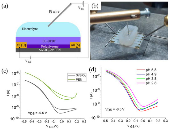
Figure 1.
(a) The device layout; (b) a photo of the setup used for electrical measurements with the device manufactured on PEN substrate; (c) typical transfer characteristics of an EGOFET recorded in 0.1 M NaCl with pH = 5.8 for devices manufactured on Si/SiO2 substrate (black) and PEN substrate (green); (d) typical transfer characteristics evolution of an EGOFET during adding of HCl for the device manufactured on Si/SiO2 substrate.
3.2. Electrical Characteristics of the Devices
In order to provide the EGOFETs testing, a PDMS reservoir was placed on the surface of the transistor, then 0.2 mL of 0.1 M NaCl was added (Figure 1b). The device showed good electrical performance: high on-off ratio, the product of charge mobility and effective capacitance, as well as a low threshold voltage. The averaged electrical parameters are shown in Table 1. The typical transfer characteristics of an EGOFET recorded in 0.1 M NaCl solution with pH = 5.8 on two different substrates are shown in Figure 1c. An example of the transfer characteristics with both drain and gate currents can be found in the Supplementary Materials in Figure S2.

Table 1.
Averaged electrical parameters of the EGOFET devices manufactured on different substrates.
In order to obtain the device response to pH variation, small volumes of acid or alkali solutions were added with different concentrations in 0.1 M NaCl to a neutral 0.1 M NaCl solution in the reservoir. It is worth noting that such a procedure allows adjusting the pH value without impact on the ionic strength of the final solution. Thus, this factor can be excluded from the list of reasons which can affect the electrical characteristics of the device [27]. A typical set of transfer characteristics of an EGOFET corresponding to different pH values is shown in Figure 1d.
3.3. Effect of HCl and NaOH Adding on the Electrical Characteristics
To clarify, which characteristics of an EGOFET are influenced by adding the acid, all electrical parameters of the device—the threshold voltage (Vth), the off-current, and the transconductance—were extracted from the transfer curves and analyzed. In order to exclude possible parameter changes during the device degradation, the operational stability was checked. By the device degradation, we understand it as electrical degradation: the threshold voltage shift (usually negative shift for p-type semiconductors), charge carrier mobility, and current decrease during the device operation [37]. In order to estimate the stability of the devices, the transfer characteristics of the EGOFET in 0.1 M NaCl solution were measured for 14 s every minute. The same measurement frequency was used for pH variation experiments. This interval was chosen because 1 min is enough to receive a dynamic response to pH change, according to the measurements of a drain current at a constant voltage during HCl addition (Figure 2a). The stability test demonstrated that an appreciable change of all the parameters was observed during the first 10–15 min (Figure 2b). Thus, before each pH experiment, 15 transfer characteristics were recorded for the system stabilization. After that, a moderate constant shift of the parameters caused by degradation was observed, which is typical for EGOFETs [30,37]: the threshold voltage shifted to negative values, while the off-current and the transconductance decreased without changing the sign (see Figure S3a–c in the Supplementary Materials). At the same time, the leakage current (IGS) decreased after stabilization during cyclic measurements (Figure S3d).
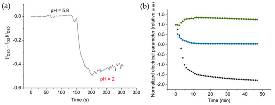
Figure 2.
(a) Drain–source current at a constant voltage during HCl addition (transient measurements). (b) Drift of the normalized electrical parameters due to device degradation during the cycling measurements at pH = 5.8 in 0.1 M NaCl water solution: the threshold voltage (black stars), the off current (blue circles), the transconductance (green squares).
Figure 3a shows that the threshold voltage shifted to positive values during pH decreasing caused by HCl addition (black dots). As the device degradation shifts Vth to the negative values, the positive shift was attributed to the effect of HCl addition. However, this dependence was not observed until the solution was adjusted to pH~5. In the range of pH = 4.9 to pH = 2.8 the threshold voltage increased significantly: the Vth–pH plot reveals an average slope of −62 ± 13 mV/pH. Using this slope as an estimation of the device’s sensitivity to pH, we can compare it to the sensitivity of the other FET-based pH sensors. The benchmark of this type of sensor is classical ISFET with a SiO2 layer as a gate material. The ideal ISFET sensitivity is determined by the Nernst equation according to the Bergveld model and predicts a shift of 59.5 mV/pH [38,39,40,41]. Thus, the pH sensitivity of the EGOFET investigated within the specified range is close to the Nernst limit and can be used to evaluate the acidity of water solutions at a constant ionic strength. At the same time, in the slightly acidic pH range (from pH = 5.8 to pH = 4.9), the threshold voltage does not demonstrate appreciable dependence on the acidity of solutions. However, the reversibility of the process check encountered some difficulties: to change the pH from acidic back to neutral, it is necessary to add an alkali solution to the acid solution in the reservoir. During this process, notable instability of all electrical parameters was observed (the threshold voltage variation is depicted in Figure S4a in the Supplementary Materials), which is probably caused by significant solution heating during the neutralization process. Therefore, a simplified procedure of the reversibility check was realized: after several measurements of the transfer characteristics in the drop of 0.1 M NaCl solution, the electrolyte was removed and replaced by a solution of HCl in 0.1 M NaCl (pH = 2). This procedure was repeated several times, and after a notable instability on the first step, the device showed rather good stability of the baseline (on current at pH = 5.8) and quick stabilization at the same value in the solution with pH = 2 (Figure S4b).
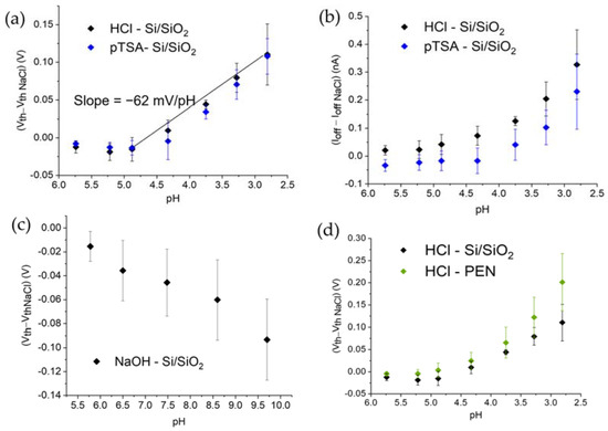
Figure 3.
The pH dependence of (a) the threshold voltage shift; (b) the off-current shift. Black dots correspond to the data obtained using hydrochloric acid and blue dots—for the data obtained with pTSA. The devices were manufactured on Si/SiO2 substrates and averaged over 5 different devices for HCl acid and for 4 devices for pTSA. (c) The pH dependence of the threshold voltage shift for the experiments with NaOH adding for devices manufactured on Si/SiO2 substrate and averaged over 4 different devices. (d) The pH dependence of the threshold voltage shift during addition of HCl acid for the devices on PEN substrate (green dots) and Si/SiO2 substrates (black dots). Each point on the plot represents a mean value and error bars correspond to the standard deviation of the data obtained.
To check if the pH dependence described above is a universal trend for the other types of acids, the experiments using the same protocol but with p-toluenesulfonic acid (pTSA) instead of HCl were performed. pTSA was chosen because the toluenesulfonate anion differs considerably from the chloride ion by size and charge distribution. The data obtained showed that the threshold voltage (Figure 3a, blue dots) and off-current (Figure 3b, blue dots) with increasing the amount of p-toluenesulfonic acid change the same way as in the experiments with HCl, which confirms that the trends described above are applicable for various acids.
Less obvious pH dependence was observed in the range of basic pH: the threshold voltage shifts to negative voltages (Figure 3c). However, as the effect of device degradation and NaOH addition on the threshold voltage are co-directional, it was not possible to distinguish between these two effects. An average slope of the Vth vs. pH plot in the pH range of 5.8–8.6 is −15 ± 9 mV, which is sufficiently weaker than the slope of the Vth vs. pH (pH sensitivity) in the acidic pH range. A more notable shift in the pH range from 8.6 to 9.7 could be caused by partial delamination of the organic semiconductor film at strongly basic solutions. Thus, the EGOFET devices based on C8-BTBT/PS blend are suitable for biosensing applications under slightly acidic or slightly basic solutions only (from pH = 8.6 to pH = 4.9) or for pH-sensing in acidic solutions in the range of pH = 4.9–2.8 with a near Nernstian sensitivity of −62 ± 13 mV/pH.
Chemical doping of OSC by polar gases such as nitrogen oxide was suggested as an explanation for the positive shift of threshold voltage in organic field-effect transistor (OFET) gas sensors [42]. Using this analogy, a positive shift of the threshold voltage in the acidic solutions of the EGOFETs could be explained by the chemical doping of the C8-BTBT organic semiconductor by protons. Nowadays, there is still a lack of information about organic semiconductor small molecules doping in water solutions. It was demonstrated that aqueous I2 solution treatment of the organic semiconducting layer in OFETs is able to reduce an interfacial charge density, which appears as a positive shift of the threshold voltage, the charge carrier mobility enhancement and does not affect the off-current [43]. Interestingly, since protons are weaker oxidants than iodine, their ability to dope chemically stable organic semiconductors is not expected. However, protons could attach to free electron pairs of sulfur atoms in C8-BTBT, leading to the formation of positive charges in the layer of organic semiconductor (Figure 4). Such charges could act as deep trap healers, which shift the threshold voltage to a positive value since a shift of the threshold voltage is usually associated with the deep traps [44]. It should be noted that similar changes in the threshold voltage in acidic solutions were also observed for EGOFETs based on the 2,6-dioctyl-tetrathienoacene (C8-TTA) organic semiconductor containing sulfur atoms [45], which is in favor of the suggested doping mechanism, including interactions of protons with sulfur atoms.
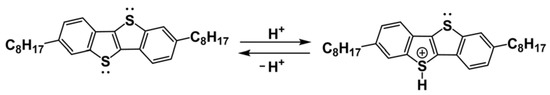
Figure 4.
The scheme proposed for doping a C8-BTBT semiconductor with protons in water-based electrolyte solutions.
The off-current demonstrated the same trend as it was observed for the threshold voltage during adding of acid (Figure 3b, black dots): there were no notable changes of the off-current with the first 2–3 portions of HCl, and then it rose by about three times with increasing pH from 4.9 to 2.8 occurred. The similarity of the threshold voltage and off-current pH dependencies points out the same reasons for the process. The pH dependence of the off-current distinguish doping of the C8-BTBT organic semiconductor by protons from doping of the OSC by iodine described above. It could be explained by the smaller size of protons that allows them to permeate into the organic semiconductor film leading to increased conductivity, which in this case should have a mixed character (electronic and ionic), including holes and protons. The absence of any notable pH dependence for the off-current in basic solutions favors this suggestion (see Figure S5a in the Supplementary Materials).
The other figure of merit that is often used as a response parameter of the FET sensors is charge carrier mobility. According to the Shockley equation (1), the charge carrier mobility is proportional to the quotient of the transconductance divided by specific capacitance per area of EDL layers (Ci) and W/L ratio: µ = gm2 2 L/(W Ci). However, since direct measurements of specific capacitance Ci in EGOFETs is a non-trivial task, one can estimate the mobility variation by extracting the transconductance from the electrical characteristics and measuring the total capacitance Ct (between the gate and the drain electrodes) during the impedance measurements. During HCl addition, a decrease in the transconductance in the whole range of pH variation was observed (Figure 5a). At the same time, the average transconductance change during the addition of NaOH is very low (see Figure S5b in the Supplementary Materials). A similar dependence of the transconductance was observed during the device degradation, and we can consider that the pH dependence of the transconductance is negligible. To prove that the transconductance decrease is caused by the mobility deterioration rather than the capacitance variation, the change of total capacitance between the source and drain electrodes during the addition of HCl to the solution was evaluated. For this goal, the immittance between the gate and drain electrodes during the portion-wise addition of HCl acid was measured according to the procedure described above. The capacitance showed moderate growth (Figure 5b), which confirms that the transconductance decrease is associated with mobility deterioration. Thereby, the protons added to the system do not improve the charge carrier mobility. It is in line with our suggestion that proton interactions with C8-BTBT lead to deep trap healing (as the threshold shift corresponds to the change of the deep trap amount [44]) and do not decrease the amount of the shallow traps associated with the charge carrier mobility [46].
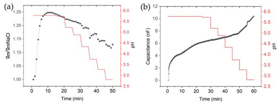
Figure 5.
Time dependences during HCl adding every 5 min for: (a) the transconductance; (b) the capacitance between the gate and the drain electrodes. The data were obtained using the devices on Si/SiO2 substrates.
3.4. Effect of the Substrate Material
The previous works on EGOFETs based on small-molecule OSC point out the important role of substrate for the device response to pH change [26,27]. It was shown that electrolyte molecules could permeate to a thin OSC layer and charge a quartz substrate, which acts as the second gate and cause the device response to pH variation [26]. In our case, the blend of C8-BTBT and polystyrene was used, which was supposed to hinder the interactions of the electrolyte ions with the substrate. Nevertheless, it was still not obvious if the pH dependence observed would remain the same for the substrate with a non-polar surface. To check this point, we repeated the experiments with HCl acid using the devices manufactured on a PEN substrate. The results obtained showed that the pH dependency of the threshold voltage (Figure 3d, green dots) shifts upon the addition of HCl acid, as in the case of the devices manufactured on Si/SiO2, but show even higher pH sensitivity. Similar trends were observed for the off-current and the transconductance (see Figure S6 in the Supplementary Materials). These results confirm that these trends are not related to proton–substrate interactions but rather can be explained by doping of the C8-BTBT OSC layer.
3.5. Flow Chamber Development and Application
For many EGOFET sensor applications, for example, body conditions monitoring or wastewater control, the device’s ability to work in continuous flow mode is very important. To check the suitability of our device for these types of applications, we designed and developed a flow chamber that allows continuous measurements in the flow mode. The flow chamber is used as follows: first, an appropriate spacer and PDMS seal are mounted on the main board. Then the sample is placed to the indention in the spacer and pressed down with a top clamp, compressing the seal and sealing the joints. The board with spring-loaded pins is pulled up with two screws, making a connection with the source and drain pads (Figure 6a). The needles are inserted through the seal and fixed by the needle-to-fitting adapters, making a connection to the pump (Figure 6b). Two dual in-line package (DMP) switches connect the transistor to a Keithley 2614 B source meter. In order to estimate the applicability of the chamber to work in a flow mode, a 24 h stability test (cyclic measurements of the transfer characteristics, one transfer curve per 30 min) was performed. After a significant shift in the first half an hour of the measurements, the current was stabilized with some constant shift (Figure 6c). Despite the two orders of magnitude decrease in the on-current, the device is still working after 24 h of continuous measurements (see Figure S7 in the Supplementary Materials). Similar time dependence was demonstrated for the operational stability of the EGOFET devices based on P3HT [37]. We also took the transient measurements during HCl acid adding to estimate the ability of the device to respond quickly to changes in the acidity in the flow mode (Figure 6d). The device showed almost the same fast response time that was registered during the transient measurement in the reservoir (about 1 min), which can be important for real-time measurements.
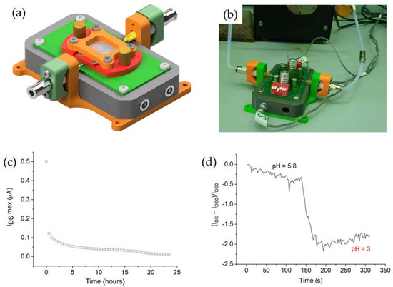
Figure 6.
(a) The rendered 3D model of the flow chamber. (b) A photo of the assembled flow chamber during the experiment. (c) Stability test (cyclic measurements, 1 transfer curve per 30 min) in the flow mode (5 mL/min). (d) Transient measurements in flow mode with HCl acid addition.
4. Conclusions
In this work, the effect of solution acidity on the electrical characteristics of C8-BTBT/PS-based EGOFETs was investigated. The devices showed significant pH dependence at the pH range of 4.9–2.8 and no notable pH dependence at the pH range of 4.9–8.6. These findings define possible application conditions of the device: it could be used for further biomodification and biosensing measurements under neutral, slightly acidic, or slightly basic solutions and could be used as a pH sensor for acidic solutions with near-Nernstian pH sensitivity. After consideration of the dependencies of different characteristics of the EGOFETs on pH values of the electrolyte solutions, a possible mechanism of the device response on acidic media was proposed, which includes doping of C8-BTBT organic semiconducting material with protons leading to deep traps healing. It appears as a positive shift of the threshold voltage and increases the off-current without influencing the charge carrier mobility. These patterns remain the same for two different types of substrates: polar Si/SiO2 and non-polar PEN, confirming that the trends observed are not related to proton–substrate interactions. It was also demonstrated that the pH dependencies are irrespective of the choice of the acid, whether it is HCl or p-toluenesulfonic acid. An EGOFET flow chamber was designed and developed for device testing under conditions close to practical applications. The measurements in a flow mode demonstrated that the system could respond quickly to pH variations and keep working for at least 24 h in the flowing solution with high ionic strength, which is important for further practical real-time applications.
Supplementary Materials
The following Supplementary Materials can be downloaded at: https://www.mdpi.com/article/10.3390/chemosensors11020074/s1. Figure S1. AFM scan of the surface of active layer at the interface between the transistor channel (the most part of the scan, pink frame) and the device contact (the upper right angle, framed with a yellow triangle): (a) topology, (b) cross-section through white line 1. Figure S2. The transfer characteristics of an EGOFET including both IDS (red curve) and IGS (black curve) registered in 0.1 M NaCl after stabilization for a typical device. Figure S3. Electrical parameters degradation of an EGOFET during cyclic measurements: (a) the threshold voltage; (b) the transconductance; (c) the off current; (d) the gate current. Figure S4. (a) The pH dependence of the threshold voltage shift during addition of HCl acid (forward, from 20 to 50 min) and NaOH solution (backward, from 50 to 80 min). (b) Variations of the on-current during successive replacements of the electrolyte from a solution with pH = 5.8 to a solution with pH = 2 and vice versa for 9 successive measurements. Figure S5. The pH dependence in basic solutions (during NaOH addition) of (a) the off-current shift; (b) the normalized transconductance shift. The data were obtained with devices manufactured on a Si/SiO2 substrate and averaged over 4 different EGOFETs. Figure S6. The pH dependencies of (a) the off-current shift; (b) the normalized transconductance shift. The data were obtained with the devices manufactured on a PEN substrate and averaged over 4 different EGOFETs. Figure S7. The transfer characteristics of an EFOFET in the flow chamber during 24 h long continues measurements: at the first measurement (circles), after 2 h (triangles), after 12 h (squares) and after 24 h (stars).
Author Contributions
Conceptualization, P.A.S., E.V.A. and S.A.P.; Methodology, E.Y.P., D.S.A., A.A.A., E.A.K. and A.A.T.; Formal analysis, P.A.S., A.A.T. and D.S.A.; Investigation, P.A.S., E.Y.P. and E.A.K.; Resources, A.A.A.; writing—original draft preparation, P.A.S., E.V.A. and A.A.A.; writing—review and editing, A.A.T., D.S.A., E.Y.P., E.A.K. and S.A.P., Supervision, E.V.A. and S.A.P.; Project administration E.V.A. and S.A.P.; Funding acquisition—S.A.P. All authors have read and agreed to the published version of the manuscript.
Funding
This research was funded by Russian Science Foundation, grant number 19-73-30028.
Institutional Review Board Statement
Not applicable.
Informed Consent Statement
Not applicable.
Data Availability Statement
The completed data of this study are available from the corresponding author.
Acknowledgments
The authors greatly thank M.S. Polinskaya (ISPM RAS, Russian Federation) for the synthesis of C8-BTBT, P.N. Karaman (ISPM RAS, Russian Federation) for the help with some EGOFET measurements, and A.E. Litvinov (ISPM RAS, Russian Federation) for fruitful discussions.
Conflicts of Interest
The authors declare no conflict of interest.
References
- Kergoat, L.; Herlogsson, L.; Braga, D.; Piro, B.; Pham, M.C.; Crispin, X.; Berggren, M.; Horowitz, G. A water-gate organic field-effect transistor. Adv. Mater. 2010, 22, 2565–2569. [Google Scholar] [CrossRef] [PubMed]
- Picca, R.A.; Manoli, K.; Macchia, E.; Sarcina, L.; Di Franco, C.; Cioffi, N.; Blasi, D.; Österbacka, R.; Torricelli, F.; Scamarcio, G.; et al. Ultimately Sensitive Organic Bioelectronic Transistor Sensors by Materials and Device Structure Design. Adv. Funct. Mater. 2020, 30, 1904513. [Google Scholar] [CrossRef]
- Wang, D.; Noël, V.; Piro, B. Electrolytic gated organic field-effect transistors for application in biosensors—A review. Electronics 2016, 5, 9. [Google Scholar] [CrossRef]
- Shaposhnik, P.A.; Zapunidi, S.A.; Shestakov, M.V.; Agina, E.V.; Ponomarenko, S.A. Modern bio and chemical sensors and neuromorphic devices based on organic semiconductors. Russ. Chem. Rev. 2020, 89, 1483–1506. [Google Scholar] [CrossRef]
- Macchia, E.; Romele, P.; Manoli, K.; Ghittorelli, M.; Magliulo, M.; Zsolt, M.K.-V.; Torricelli, F.; Luisa, T. Ultra-sensitive protein detection with organic electrochemical transistors printed on plastic substrate. Flex. Print. Electron. 2018, 034002. [Google Scholar] [CrossRef]
- Macchia, E.; Manoli, K.; Di Franco, C.; Scamarcio, G.; Torsi, L. New trends in single-molecule bioanalytical detection. Anal. Bioanal. Chem. 2020, 412, 5005–5014. [Google Scholar] [CrossRef]
- Seo, G.; Lee, G.; Kim, M.J.; Baek, S.H.; Choi, M.; Ku, K.B.; Lee, C.S.; Jun, S.; Park, D.; Kim, H.G.; et al. Rapid Detection of COVID-19 Causative Virus (SARS-CoV-2) in Human Nasopharyngeal Swab Specimens Using Field-Effect Transistor-Based Biosensor. ACS Nano 2020, 14, 5135–5142. [Google Scholar] [CrossRef]
- Guo, K.; Wustoni, S.; Koklu, A.; Díaz-Galicia, E.; Moser, M.; Hama, A.; Alqahtani, A.A.; Ahmad, A.N.; Alhamlan, F.S.; Shuaib, M.; et al. Rapid single-molecule detection of COVID-19 and MERS antigens via nanobody-functionalized organic electrochemical transistors. Nat. Biomed. Eng. 2021, 5, 666–677. [Google Scholar] [CrossRef]
- Liu, H.; Yang, A.; Song, J.; Wang, N.; Lam, P.; Li, Y.; Law, H.K.; Yan, F. Ultrafast, sensitive, and portable detection of COVID-19 IgG using flexible organic electrochemical transistors. Sci. Adv. 2021, 7, 8387. [Google Scholar] [CrossRef]
- Desbief, S.; di Lauro, M.; Casalini, S.; Guerin, D.; Tortorella, S.; Barbalinardo, M.; Kyndiah, A.; Murgia, M.; Cramer, T.; Biscarini, F.; et al. Electrolyte-gated organic synapse transistor interfaced with neurons. Org. Electron. 2016, 38, 21–28. [Google Scholar] [CrossRef]
- Lee, Y.; Lee, T.-W.W. Organic Synapses for Neuromorphic Electronics: From Brain-Inspired Computing to Sensorimotor Nervetronics. Acc. Chem. Res. 2019, 52, 964–974. [Google Scholar] [CrossRef] [PubMed]
- Di Lauro, M.; Berto, M.; Giordani, M.; Benaglia, S.; Schweicher, G.; Vuillaume, D.; Bortolotti, C.A.; Geerts, Y.H.; Biscarini, F. Liquid-Gated Organic Electronic Devices Based on High-Performance Solution-Processed Molecular Semiconductor. Adv. Electron. Mater. 2017, 3, 1700159. [Google Scholar] [CrossRef]
- Kim, D.H.; Yoon, S.M. Improvement in energy consumption and operational stability of electrolyte-gated synapse transistors using atomic-layer-deposited HfO2 thin films. Mater. Sci. Semicond. Process. 2023, 153, 107182. [Google Scholar] [CrossRef]
- Parkula, V.; Maglione, M.S.; Casalini, S.; Zhang, Q.; Greco, P.; Bortolotti, C.A.; Rovira, C.; Mas-Torrent, M.; Biscarini, F. EGOFET Gated by a Molecular Electronic Switch: A Single-Device Memory Cell. Adv. Electron. Mater. 2019, 5, 1800875. [Google Scholar] [CrossRef]
- Seshadri, P.; Manoli, K.; Schneiderhan-Marra, N.; Anthes, U.; Wierzchowiec, P.; Bonrad, K.; Di Franco, C.; Torsi, L. Low-picomolar, label-free procalcitonin analytical detection with an electrolyte-gated organic field-effect transistor based electronic immunosensor. Biosens. Bioelectron. 2018, 104, 113–119. [Google Scholar] [CrossRef]
- Cramer, T.; Kyndiah, A.; Murgia, M.; Leonardi, F.; Casalini, S.; Biscarini, F. Double layer capacitance measured by organic field effect transistor operated in water. Appl. Phys. Lett. 2012, 100, 86. [Google Scholar] [CrossRef]
- Poimanova, E.Y.; Shaposhnik, P.A.; Anisimov, D.S.; Zavyalova, E.G.; Trul, A.A.; Skorotetcky, M.S.; Borshchev, O.V.; Vinnitskiy, D.Z.; Polinskaya, M.S.; Krylov, V.B.; et al. Biorecognition Layer Based On Biotin-Containing [1]Benzothieno[3,2-b][1]benzothiophene Derivative for Biosensing by Electrolyte-Gated Organic Field-Effect Transistors. ACS Appl. Mater. Interfaces 2022, 14, 16462–16476. [Google Scholar] [CrossRef]
- Arlett, J.L.; Myers, E.B.; Roukes, M.L. Comparative advantages of mechanical biosensors. Nat. Nanotechnol. 2011, 6, 203–215. [Google Scholar] [CrossRef]
- Lichtenberg, J.Y.; Ling, Y.; Kim, S. Non-specific adsorption reduction methods in biosensing. Sensors 2019, 19, 2488. [Google Scholar] [CrossRef]
- Nikolka, M.; Simatos, D.; Foudeh, A.; Pfattner, R.; Mcculloch, I.; Bao, Z. Low-voltage, Dual-gate Organic Transistors with High-sensitivity and Stability towards Electrostatic Biosensing. ACS Appl. Mater. Interfaces 2020, 12, 40581–40589. [Google Scholar] [CrossRef]
- Coyle, S.; Morris, D.; Lau, K.; Diamond, D.; Di Francesco, F.; Taccini, N.; Trivella, M.G.; Clinica, F.; Costanzo, D.; Salvo, P. Textile sensors to measure sweat pH and sweat-rate during exercise. In Proceedings of the 3rd International Conference on Pervasive Computing Technologies for Healthcare, London, UK, 1–3 April 2009. [Google Scholar]
- Maalouf, N.M.; Cameron, M.A.; Moe, O.W.; Adams-Huet, B.; Sakhaee, K. Low urine pH: A novel feature of the metabolic syndrome. Clin. J. Am. Soc. Nephrol. 2007, 2, 883–888. [Google Scholar] [CrossRef] [PubMed]
- Dang, W.; Manjakkal, L.; Navaraj, W.T.; Lorenzelli, L.; Vinciguerra, V.; Dahiya, R. Stretchable wireless system for sweat pH monitoring. Biosens. Bioelectron. 2018, 107, 192–202. [Google Scholar] [CrossRef] [PubMed]
- Islam, A.; Dey, S. A Review on Textile Wastewater Characterization in Bangladesh. Resour. Environ. 2015, 5, 15–44. [Google Scholar] [CrossRef]
- Alam, A.U.; Qin, Y.; Nambiar, S.; Yeow, J.T.W.; Howlader, M.M.R.; Hu, N.X.; Deen, M.J. Polymers and organic materials-based pH sensors for healthcare applications. Prog. Mater. Sci. 2018, 96, 174–216. [Google Scholar] [CrossRef]
- Di Lauro, M.; Casalini, S.; Berto, M.; Campana, A.; Cramer, T.; Murgia, M.; Geoghegan, M.; Bortolotti, C.A.; Biscarini, F. The substrate is a pH-controlled second gate of electrolyte-gated organic field-effect transistor. ACS Appl. Mater. Interfaces 2016, 8, 31783–31790. [Google Scholar] [CrossRef]
- Buth, F.; Kumar, D.; Stutzmann, M.; Garrido, J.A. Electrolyte-gated organic field-effect transistors for sensing applications. Appl. Phys. Lett. 2011, 98, 2009–2012. [Google Scholar] [CrossRef]
- Sinno, H.; Fabiano, S.; Crispin, X.; Berggren, M.; Engquist, I. Bias stress effect in polyelectrolyte-gated organic field-effect transistors. Appl. Phys. Lett. 2013, 102, 113306. [Google Scholar] [CrossRef]
- Ebata, H.; Izawa, T.; Miyazaki, E.; Takimiya, K.; Ikeda, M.; Kuwabara, H.; Yui, T. Highly Soluble [1] Benzothieno [3, 2-b] benzothiophene (BTBT) Derivatives for. J. Am. Chem. Soc. 2007, 129, 15732–15733. [Google Scholar] [CrossRef]
- Zhang, Q.; Leonardi, F.; Casalini, S.; Temiño, I.; Mas-Torrent, M. High performing solution-coated electrolyte-gated organic field-effect transistors for aqueous media operation. Sci. Rep. 2016, 6, 39623. [Google Scholar] [CrossRef]
- Zaumseil, J.; Sirringhaus, H. Electron and ambipolar transport in organic field-effect transistors. Chem. Rev. 2007, 107, 1296–1323. [Google Scholar] [CrossRef]
- Wu, X.; Jia, R.; Jie, J.; Zhang, M.; Pan, J.; Zhang, X.; Zhang, X. Air Effect on the Ideality of p-Type Organic Field-Effect Transistors: A Double-Edged Sword. Adv. Funct. Mater. 2019, 29, 1906653. [Google Scholar] [CrossRef]
- Xie, P.; Liu, T.; Sun, J.; Yang, J. Structures, Properties, and Device Applications for [1]Benzothieno[3,2-b]Benzothiophene Derivatives. Adv. Funct. Mater. 2022, 32, 2200843. [Google Scholar] [CrossRef]
- Shaposhnik, P.A.; Anisimov, D.A.; Trul, A.A.; Agina, E.V.; Ponomarenko, S.A. A Simple Approach to Fabrication of Highly Efficient Electrolyte-Gated Organic Transistors by Phase Microsegregation of 2,7-Dioctyl [1]benzothieno[3,2-b]benzothiophene and Polystyrene Mixtures. Dokl. Phys. Chem. 2021, 496, 20–24. [Google Scholar] [CrossRef]
- Pérez-Rodríguez, A.; Temiño, I.; Ocal, C.; Mas-Torrent, M.; Barrena, E. Decoding the Vertical Phase Separation and Its Impact on C8-BTBT/PS Transistor Properties. ACS Appl. Mater. Interfaces 2018, 10, 7296–7303. [Google Scholar] [CrossRef]
- Kyndiah, A.; Leonardi, F.; Tarantino, C.; Cramer, T.; Millan-Solsona, R.; Garreta, E.; Montserrat, N.; Mas-Torrent, M.; Gomila, G. Bioelectronic Recordings of Cardiomyocytes with Accumulation Mode Electrolyte Gated Organic Field Effect Transistors. Biosens. Bioelectron. 2020, 150, 111844. [Google Scholar] [CrossRef] [PubMed]
- Picca, R.A.; Manoli, K.; Macchia, E.; Tricase, A.; Di Franco, C.; Scamarcio, G.; Cioffi, N.; Torsi, L. A Study on the Stability of Water-Gated Organic Field-Effect-Transistors Based on a Commercial p-Type Polymer. Front. Chem. 2019, 7, 667. [Google Scholar] [CrossRef]
- Knopfmacher, O.; Tarasov, A.; Fu, W.; Wipf, M.; Niesen, B.; Calame, M.; Schönenberger, C. Nernst limit in dual-gated Si-nanowire FET sensors. Nano Lett. 2010, 10, 2268–2274. [Google Scholar] [CrossRef] [PubMed]
- Bergveld, P. Thirty years of ISFETOLOGY: What happened in the past 30 years and what may happen in the next 30 years. Sens. Actuators B Chem. 2003, 88, 1–20. [Google Scholar] [CrossRef]
- Spijkman, M.J.; Brondijk, J.J.; Geuns, T.C.T.; Smits, E.C.P.; Cramer, T.; Zerbetto, F.; Stoliar, P.; Biscarini, F.; Blom, P.W.M.; De Leeuw, D.M. Dual-gate organic field-effect transistors as potentiometrie sensors in aqueous solution. Adv. Funct. Mater. 2010, 20, 898–905. [Google Scholar] [CrossRef]
- Jung, S.H.; Seo, Y.M.; Gu, T.; Jang, W.; Kang, S.G.; Hyeon, Y.; Hyun, S.H.; Lee, J.H.; Whang, D. Super-Nernstian pH Sensor Based on Anomalous Charge Transfer Doping of Defect-Engineered Graphene. Nano Lett. 2021, 21, 34–42. [Google Scholar] [CrossRef]
- Cramer, T.; Campana, A.; Leonardi, F.; Casalini, S.; Kyndiah, A.; Murgia, M.; Biscarini, F. Water-gated organic field effect transistors-opportunities for biochemical sensing and extracellular signal transduction. J. Mater. Chem. B 2013, 1, 3728–3741. [Google Scholar] [CrossRef] [PubMed]
- Li, J.; Babuji, A.; Temiño, I.; Salzillo, T.; D’Amico, F.; Pfattner, R.; Ocal, C.; Barrena, E.; Mas-Torrent, M. Chemical Doping of the Organic Semiconductor C8-BTBT-C8 Using an Aqueous Iodine Solution for Device Mobility Enhancement. Adv. Mater. Technol. 2022, 7, 2101535. [Google Scholar] [CrossRef]
- Völkel, A.R.; Street, R.A.; Knipp, D. Carrier transport and density of state distributions in pentacene transistors. Phys. Rev. B - Condens. Matter Mater. Phys. 2002, 66, 1953361–1953368. [Google Scholar] [CrossRef]
- Poimanova, E.Y.; Shaposhnik, P.A.; Karaman, P.N.; Anisimov, D.S.; Skorotetcky, M.S.; Polinskaya, M.S.; Borshchev, O.V.; Agina, E.V.; Ponomarenko, S.A. Electrolyte-gated organic field-effect transistors based on 2,6-dioctyltetrathienoacene as a convenient platform for fabrication of liquid biosensors. Russ. Chem. Bull. 2022, 71, 2116–2122. [Google Scholar] [CrossRef]
- Li, C.; Duan, L.; Li, H.; Qiu, Y. Universal trap effect in carrier transport of disordered organic semiconductors: Transition from shallow trapping to deep trapping. J. Phys. Chem. C 2014, 118, 10651–10660. [Google Scholar] [CrossRef]


Disclaimer/Publisher’s Note: The statements, opinions and data contained in all publications are solely those of the individual author(s) and contributor(s) and not of MDPI and/or the editor(s). MDPI and/or the editor(s) disclaim responsibility for any injury to people or property resulting from any ideas, methods, instructions or products referred to in the content. |
© 2023 by the authors. Licensee MDPI, Basel, Switzerland. This article is an open access article distributed under the terms and conditions of the Creative Commons Attribution (CC BY) license (https://creativecommons.org/licenses/by/4.0/).