Article

Self-Powered Wearable Breath-Monitoring Sensor Enabled by Electromagnetic Harvesting Based on Nano-Structured Electrochemically Active Aluminum

by
Marko V. Bošković
,
Miloš Frantlović
,
Evgenija Milinković
,
Predrag D. Poljak
,
Dana Vasiljević Radović
,
Jelena N. Stevanović
and
Milija Sarajlić
*
Center for Microelectronic Technologies, Institute of Chemistry, Technology and Metallurgy, National Institute of the Republic of Serbia, University of Belgrade, Njegoševa 12, 11000 Belgrade, Serbia
*
Author to whom correspondence should be addressed.
Chemosensors 2023, 11(1), 51; https://doi.org/10.3390/chemosensors11010051
Submission received: 9 December 2022 / Revised: 2 January 2023 / Accepted: 4 January 2023 / Published: 7 January 2023

Abstract

:
Self-powered sensors are gaining a lot of attention in recent years due to their possible application in the Internet of Things, medical implants and wireless and wearable devices. Human breath detection has applications in diagnostics, medical therapy and metabolism monitoring. One possible approach for breath monitoring is detecting the humidity in exhaled air. Here, we present an extremely sensitive, self-powered sensor for breath humidity monitoring. As a power source, the sensor uses electromagnetic energy harvested from the environment. Even electromagnetic energy harvested from the human body is enough for the operation of this sensor. The signal obtained using the human body as a source was up to 100 mV with an estimated power of 1 nW. The relatively low amount of energy that could be harvested in this way was producing a signal that was modulated by an interdigitated capacitor made out of electrochemically activated aluminum. The signal obtained in this way was rectified by a set of Schottky diodes and measured by a voltmeter. The sensor was capable of following a variety of different respiration patterns during normal breathing, exercise and rest, at the same time powered only by electromagnetic energy harvested from the human body. Everything happened in the normal environment used for everyday work and life, without any additional sources, and at a safe level of electromagnetic radiation.

1. Introduction

Human respiration can be used for the detection of overall health status [1,2,3]. There are hundreds of different substances present in exhaled breath [3]. Monitoring these substances in the exhaled air can provide data about the health condition and functioning of the body as a whole. Nevertheless, the presence of humidity is also important for the body’s functioning. In a healthy individual, the relative humidity of the exhaled breath is 95%. In the case of certain illnesses, this value can go down [3]. For this reason, monitoring humidity in human respiration can indicate specific health conditions. At the same time, detecting humidity in the exhaled air can serve as a respiration monitoring approach [1,2,3,4]. The field of wearable health monitoring systems is developing rapidly with new solutions emerging almost every day [5].
There is a wide variety of methods and devices that can be used to measure humidity in air. It is a very popular topic and some of the recent developments include graphene [6,7], optical microfiber [8], luminescent metal-organic frameworks [9], Mn2O3 particles [10], TiO2 modified by Au nanoparticles [11], cellulose [12] and paper-based sensors [13]. The introduction of flexible humidity sensors brings specific advantages in emerging applications such as armband-shaped sensing devices or smart textiles with incorporated sensors [14]. Additionally, self-powered humidity sensors are of key importance for the transition to wearable devices [15].
Self-powered sensors are ideally suited for battery-operated systems, the Internet of Things (IoT), medical implants, wireless devices [16,17] and wearable applications [1,18]. A self-powered device harvests energy available from the environment in order to power the sensing element. Mainly, triboelectric and piezoelectric nanogenerators (TENG and PENG) are utilized as a power source [19,20]. In the field of self-powered humidity sensors, one approach is to generate electricity directly from moisture and use it as a humidity detector [21,22,23,24,25,26,27,28,29], even though this approach can only provide the ability to detect the difference between very high and very low humidity levels. Other examples are based on TiO2 nanowire networks [15,30] and the aluminum–air battery principle [31,32]. Aluminum–air batteries represent a specific example of the much wider class of the so-called “metal–gas” batteries [33].
It has already been shown that the structure of an interdigitated capacitor made out of activated aluminum can serve as a humidity sensor and, at the same time, as a power source [31]. It was shown that this structure reacted in the presence of high humidity levels, close to 100% RH [31]. It was also proven [32] that the signal from this kind of structure was a consequence of the electrochemical reaction between aluminum and water on the surface of the sensor. In this work, the concept of a sensor based on activated aluminum is extended by adding electromagnetic (EM) harvesting and an electronic rectifier in order to modulate the output from the EM antenna. In this way, a very sensitive, self-powered and wearable breath-monitoring sensor was obtained, capable of monitoring human respiration in various situations during exercise and rest. Self-powered respiration monitoring is gaining significant interest in the scientific community due to various important applications such as health monitoring and exercise tracking, but with less reliance on conventional power sources, since the power is derived from the environment where the measurement is performed [1,20,30].
EM harvesting can be utilized as a power source in applications with very low power demands [5,34,35,36,37,38,39]. For the first time, it is shown in this work that it is possible to harvest EM energy by using the human body as an antenna and to modulate the obtained voltage by using a humidity sensor with activated aluminum electrodes in order to detect human breathing. The concept of an aluminum–air battery with mono-material electrodes and signal rectification with added EM harvesting is used to form a self-powered humidity sensor with the capability of extremely sensitive monitoring of human respiration. The sensor is based on a unique coupling between the EM-harvested energy and the electrochemical process on the surface of the activated aluminum electrodes. In this way, the voltage obtained from EM energy is modulated by the electrochemical energy coming from the aluminum–air battery formed by the sensor electrodes. So far, human body energy has been harvested by thermal, mechanical and chemical processes [40]. EM energy has also been harvested from the human body, but with the use of specially designed devices for that purpose [40,41]. Here, it is shown for the first time that EM energy can be harvested directly from the human body without additional devices, and used in a self-powered humidity sensor that, in turn, enables human respiration monitoring. It is important to mention that the EM radiation in the lab during the experiments was at the normal level, acceptable for everyday work or living. No extra EM sources were needed to enable the operation of this sensor set-up.

2. Materials and Methods
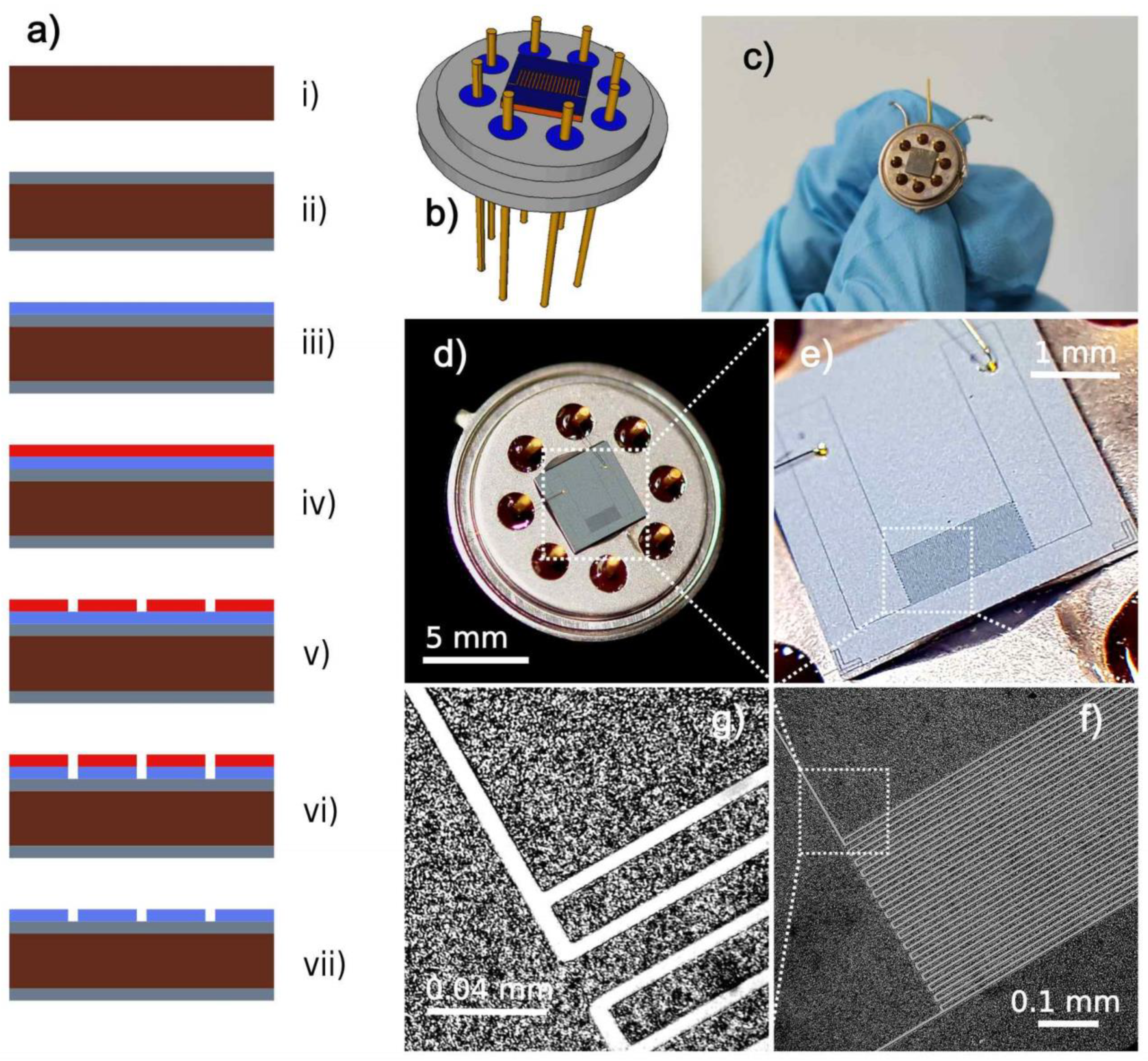
2.1. Fabrication

The sensor was made on a silicon wafer, 3” in diameter, single side polished, n-type, 3–5 Ωcm resistance, <100> orientation, Figure 1a(i–vii). Thermal SiO2 was grown on top of the Si wafer by thermal oxidation until a 600 nm thick oxide layer was formed. The wafer was then coated with a 700 nm thick layer of aluminum–silicon alloy (Al-1%Si) by sputtering (Sputtersphere, MRC, Orangeburg, NY, USA). Subsequently, the wafer was coated with 500 nm thick photoresist (AZ 1505, MicroChemicals, Ulm, Germany) by spin coating. Afterwards, the wafer was exposed to laser light by using a laser writer (LW405, MicroTech, Palermo, Italy) in vector mode, so that the designed pattern was polymerized in photoresist. The photoresist was developed, thus forming the designed structure. The final structure in Al-1%Si was formed by wet etching, using a mixture of H3PO4 80% (volumetric), HNO3 5%, CH3COOH 5% and H2O 10%. The remaining photoresist was removed using acetone. The wafer was diced and the best chips were glued to TO-8 housings. Electrical connections were made by wire bonding. The 3D design of the sensor chip on the TO-8 housing is given in Figure 1b. The photograph of the finished sensor is given in Figure 1c,d. The micrograph of the finished sensor is given in Figure 1e, as seen by using a 3D stereo microscope. A single chip contains one humidity sensor battery. Figure 1f shows a detail of the finished structure. The clearance between the digits was measured from the micrograph in Figure 1g, and estimated at 0.005 mm, while the width of the digits was 0.015 mm.

2.2. Activation

The method of aluminum activation described here is a novel method, discovered and used for the first time for aluminum-battery-based sensor activation [31,32]. Other methods have been used for aluminum activation [42,43]. The sensor was connected to a constant current source (Keithley 220, Programmable Current Source, Beaverton, OR, USA). A single drop of demineralized water was deposited onto the electrodes. A current of 0.001 mA was then applied. The voltage at the sensor contacts was monitored. The voltage signal exhibited a specific behavior, which recurred at all activated sensors. The voltage value increased steadily towards the saturation value. At a specific point in time, the voltage suddenly dropped, which was recognized as the surface oxide removal. After this point, the sensor was activated and ready for deployment.

2.3. Longevity

The longevity was tested by placing the aluminum-based sensor in a closed glass flask (250 mL) with a small amount of demineralized water (3 mL) at the bottom. The test has been run for more than 15 months now (Dec., 2022). The strength of the electrochemical signal has been stable through this period with no signs of fading away.

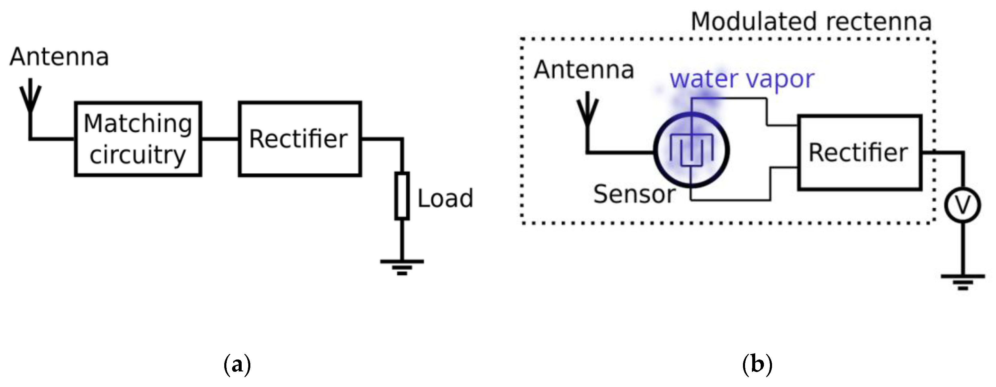
2.4. Concept of the Sensor Operation

A typical EM harvesting system consists of an antenna, a matching circuitry and a rectifier [35], Figure 2a. In the literature, this kind of a system is called a rectenna [36]. The harvested energy will then be used to power a useful device, such as a sensor or detector [37]. The amount of harvested EM energy is typically very small [38], which is the main limiting factor for applications in many fields. It is always in question whether the harvested energy is enough to power a useful device.
In the approach presented in this paper, we actually modulate the output from a rectenna by applying various levels of humidity, Figure 2b. Instead of harvesting EM energy and leading the energy to the humidity sensor, the rectenna system is a humidity sensor itself, Figure 2b. The matching circuitry from Figure 2a is now replaced with an interdigitated capacitor made out of activated aluminum. In this way, we achieve humidity sensing where the same task would be much harder to accomplish by using a typical EM harvesting system and a humidity sensor powered by it.
The sensor housing, Figure 3a, was connected to the harvesting antenna. The EM harvesting was tested by using two separate antennas, (1) a wire connected to the building foundation and (2) the human body. In the case of the human body, the volunteer had an antistatic wrist strap around his arm by which the signal harvested from his own body was connected to the sensor housing. In the case of the building foundation, a wire (copper, 10 mm2) was connected from the set-up in the lab to the building foundation iron bars in the basement, thus acting as an antenna and providing the most effective harvesting of the EM energy from the environment. In both cases, the collected EM energy was transferred from the sensor housing, through the layer of adsorbed water vapor, to the interdigitated electrodes made out of electrochemically active aluminum thin film. The activated aluminum facilitated water vapor adsorption on the surface of the electrodes due to the electrochemical reaction between aluminum and water. At the same time, the sensor’s output signal was formed by combining the voltage obtained by EM energy harvesting and the voltage generated by the electrochemical process occurring on the aluminum electrodes. The signal was then passed through the rectifier consisting of four Schottky diodes (STPS1150) [44]. The rectified signal was measured by a DC voltmeter (Keysight 34461A, Santa Rosa, CA, USA).
Figure 3b shows the equivalent circuit of the sensor connected to the rectifier and voltmeter. The element Cb is the capacitor formed by the interdigitated electrodes. The element Rb is the resistor formed by the thin water layer on the surface of the sensor. The element Eb represents the electromotive force generated by the aluminum–water reaction. The element Ca is the capacitor formed by the layer of adsorbed water between the electrodes and the sensor housing. The element Ra is the resistor formed by the layer of adsorbed water between the electrodes and the sensor housing. The sensor housing is connected to the EM harvesting antenna, which, in this work, could be a wire connected to the building foundation or human body. The voltage output measured by the voltmeter is 0.6 V lower than that produced by the harvesting system since the signal needs to cross two diodes, where each diode is producing a 0.3 V voltage drop [44]. Without the EM harvesting antenna connected to the sensor housing, the output signal measured by the voltmeter is very faint and indistinguishable from the noise due to the presence of the 0.6 V voltage drop introduced by the diodes. With EM harvesting from the sensor housing and the building foundation antenna, the output signal can reach up to 500 mV depending on the humidity applied. With EM harvesting from the human body, the output signal can reach up to 100 mV. The cables between the rectifier and the voltmeter were shielded and the shield was grounded. The voltmeter was also grounded in order to avoid EM interference from external sources.

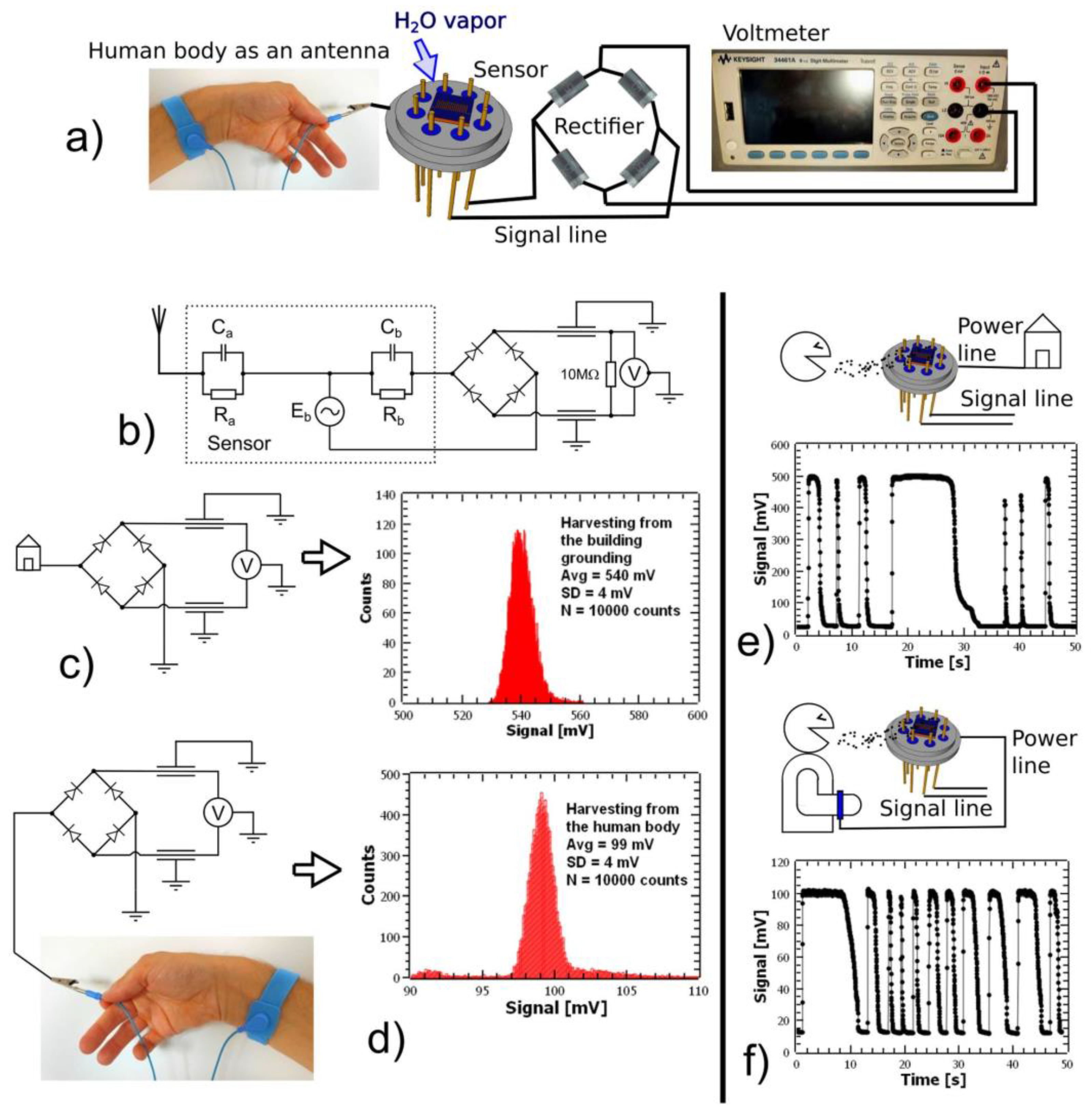
2.5. EM Energy Harvesting Quantification

In order to quantify the influence of EM energy harvesting on the sensor’s output signal, the voltage from the EM harvesting antenna was rectified using the full bridge Schottky rectifier, whose output was connected to the input of the voltmeter, Figure 3c,d. The same procedure was performed for the EM energy harvesting realized by using a wire connected to the building foundation, Figure 3c, and the EM energy harvesting from the human body using an antistatic wrist strap on the volunteer’s arm, Figure 3d. The signal harvested from the building foundation has a histogram with the average value of 540 mV, and standard deviation of 4 mV (statistics calculated based on 10,000 measurements). The signal harvested from the human body, using an antistatic wrist strap as a contact between the sensor housing and the volunteer’s body, has a histogram with the average value of 99 mV, and standard deviation of 4 mV (statistics calculated based on 10,000 measurements). The power obtained by EM harvesting in this way was up to 30 nW for the building foundation and around 1 nW for the human body harvesting. It is clear that the signal harvested from the building foundation was much stronger than the signal harvested from the human body, but nevertheless, even the human body can be used as an antenna for EM harvesting in this set-up. Here, it is important to mention that there was no special EM source in the lab provided for these measurements. The EM radiation came from the sources which are normally present in the lab on a daily basis. The measurements performed by using an oscilloscope (Siglent SDS5032X, Shenzhen, China) revealed that most of the EM harvesting came from the power network operating at 50 Hz. At the same time, the EM field measured by the field meter (Mastfuyi, FY8812, Guangdong, China) at the point of the sensor and the place of the volunteer showed zero V/m intensity.

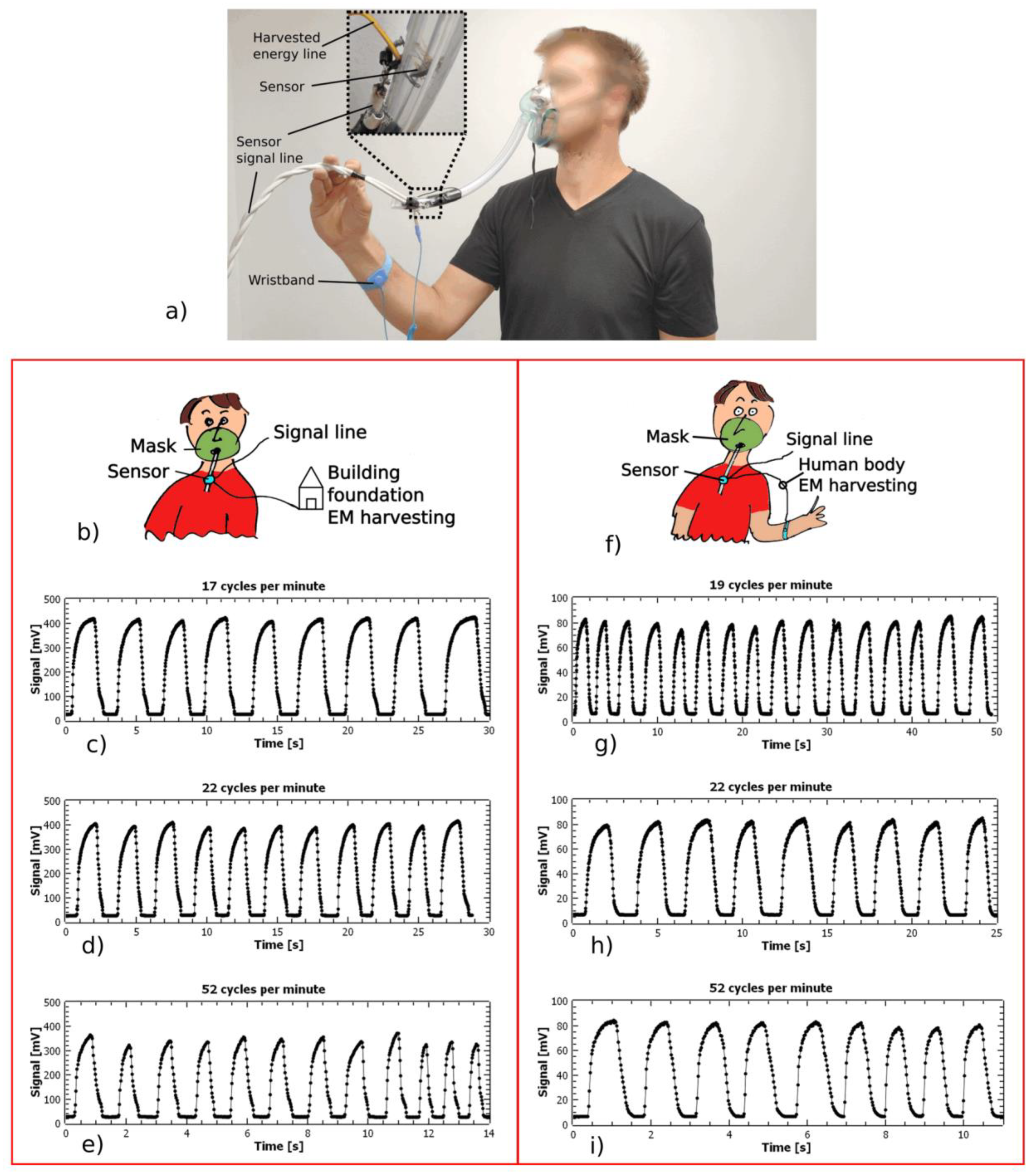
2.6. Direct Breath Blow Test

In order to test the responsiveness of the sensor system, a test with direct breath blow on the sensor surface was performed for the EM harvesting coming from the building foundation, Figure 3e, and, separately, for the EM harvesting coming from the volunteer’s body, Figure 3f. The volunteer was blowing directly on the sensor surface from a distance of about 10 cm. The breath blow pattern was examined for the short blow, as well as for the longer ones. The sensor can clearly discern between different phases of the breath blow, at the same time having a speed of response high enough to follow humidity adsorption and desorption from the sensor’s surface. The ambient humidity in the lab during this experiment was 35% RH, measured by a humidity meter (Testo 440, Titisee-Neustadt, Germany).
In the case of EM harvesting from the building foundation, the signal during direct breath blow reached values equal to 500 mV, which was the average value of the histogram in Figure 3c. This means that the voltage drop between the sensor housing and the interdigitated (ID) electrodes was practically zero, i.e., the impedance was very low. This could be the consequence of the aluminum ID electrodes adding OH ions into the adsorbed water and the electrochemical reaction adding energy into the process of EM harvesting. For a dry sensor, the impedance between the housing and the chip electrodes was 10 MΩ at 50 Hz frequency, measured using an LCR meter (GW Instek, LCR-6200, Taipei, Taiwan). For a humid sensor, this impedance was as low as 10 kΩ, which is less by a factor of 1000.
In the case of EM harvesting from the human body using a wristband, the signal during a direct breath blow reached values equal to 100 mV, which was the average value of the histogram in Figure 3d. Even though the signal was lower than in the case of EM harvesting from the building foundation, it showed no signs of quality deterioration. The sensor was still capable of clearly following the sequence of water vapor adsorption and desorption from the surface, at the same time following direct blow patterns, long and short breath sequences, the duration of each breath blow and its intensity. This experiment shows that even the relatively low amount of EM energy that could be harvested in this way is enough for the sensor’s operation. This opens up a door for wearable applications of this breath-detection set-up.

2.7. Software

All diagrams were prepared using “Sci Davis” software (Sci Davis, version 1.22, International). Illustrations were made using “Inkscape” software (Inkscape, version 1.1, International). All figures were edited using “Fast Stone” (FastStone Soft, version 7.5, Alberta, Canada) and “GIMP” software (Spencer Kimball, Peter Mattis and the GIMP Development Team, version 2.10.28, International). The aluminum crystal lattice and molecular structures were modeled using “Jmol” software (Jmol, version 14.32, International) [45]. 3D modeling was carried out using “FreeCAD” software (FreeCAD, version 0.19, International).

3. Results

3.1. Mask Breathing and Respiration Monitoring

The sensor connected to EM harvesting and signal rectification was utilized as a breath-detection device. The sensor was placed at the end of a flexible tube, while the other end was connected to the breathing mask, normally used for a patient’s oxygen supply (Idunmed, Ningbo, China), Figure 4a. The sensor was positioned inside of the tube, so that the inhaled and exhaled air could have an unobstructed flow through the tube and across the sensor’s surface, Figure 4a (inset). The experiment was conducted using nose breathing. The volunteer was breathing using the mask while sitting at rest and simulating fast and normal breathing. The EM energy for the sensor operation was harvested from the building foundation, Figure 4b. The output from the sensor after signal rectification is given in Figure 4c–e. The signal from the sensor was recorded by the voltmeter with a time resolution of 20 ms. Breathing detection was examined at various speeds: 17 cpm (cycles per minute), which is normal breathing, Figure 4c, 22 cpm (slightly faster than normal breathing), Figure 4d, and 52 cpm (very fast breathing) Figure 4e. In the second run of the experiment, the EM energy for the sensor operation was harvested from the volunteer’s body using the wristband, Figure 4f. The breathing detection was examined at three speeds: 19 cpm, which is normal breathing, Figure 4g, 22 cpm (slightly faster than normal breathing), Figure 4h, and 52 cpm (very fast breathing), Figure 4i. It is clear that the sensor was capable of resolving and following the breathing process in all cases. The experiment with the building foundation as an EM source gives a higher signal level, since the harvested EM power is higher than in the case of the wristband. Nevertheless, the signal with the human body EM harvesting using the wristband was strong and clear enough, which makes wearable applications possible.

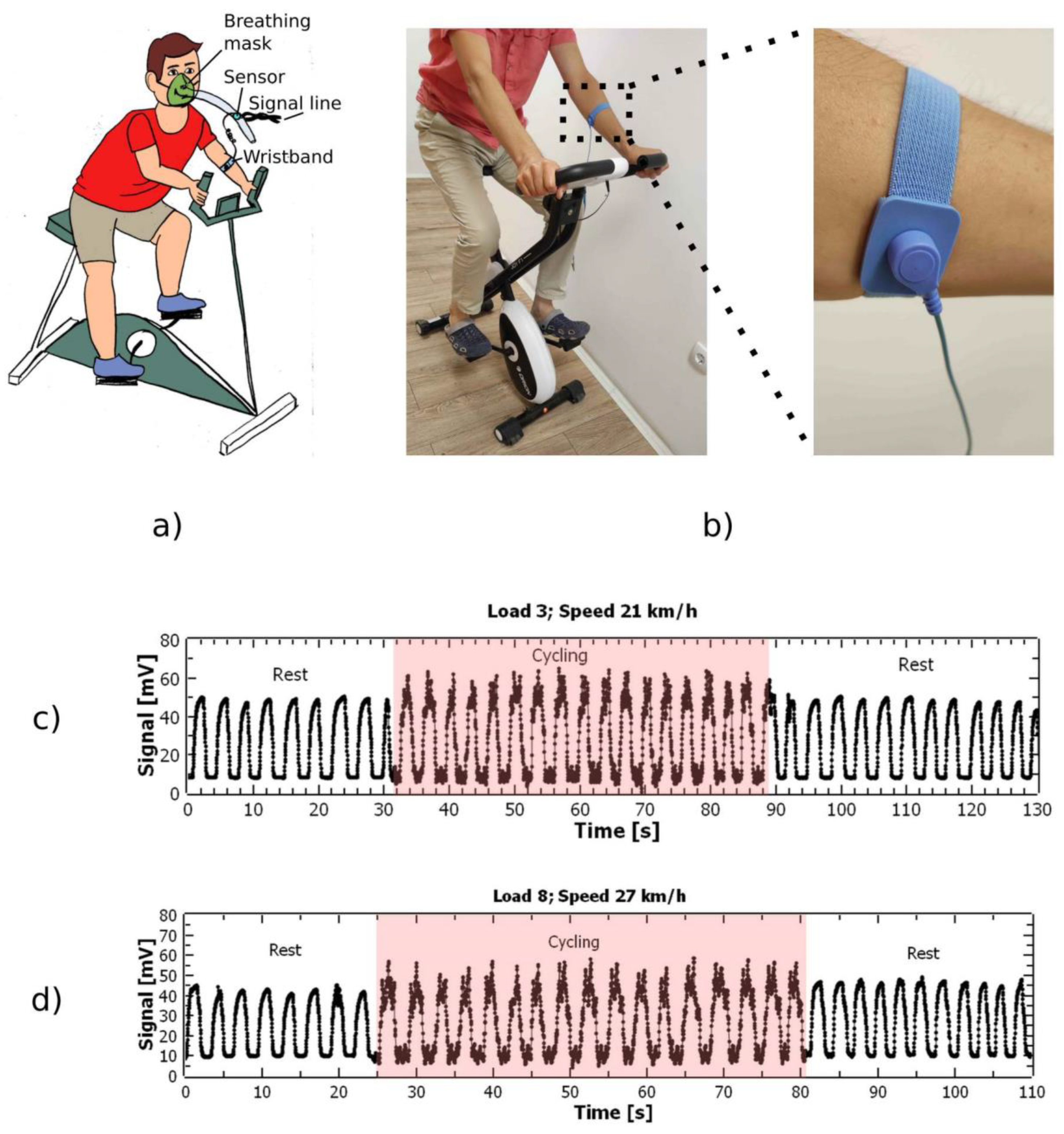
3.2. Wearable Applications

In order to assess the usability of the sensor for wearable applications, a test with respiration monitoring while exercising was performed. An exercise bicycle was used by the volunteer in order to carry out a cycling exercise while breathing through the mask with the sensor attached, Figure 5a,b. The sensor was connected to the EM harvesting through the wristband, thus using the body of the volunteer as a source of power. By this approach, a truly wearable respiration monitoring was performed. In Figure 5c,d, the results of the measurement are shown. The respiration rate of the volunteer was measured starting from the rest, cycling on various loads and speeds and resting again. In Figure 5c, the respiration for load 3 on the bicycle and the speed of 21 km/h is shown. In Figure 5d, the respiration was recorded for load 8 and the speed of 27 km/h. The load on the bicycle increased from 1 to 8. The sensor was capable of following the respiration of the volunteer with the antistatic wrist strap in all situations. The increase in noise visible in Figure 5c,d during cycling is associated with the influence of the exercise, as it had an EM control of the load exerted on the driver. The load on the volunteer was not enough to produce a significant difference in the breathing pattern but it was important to see that the sensor was applicable in this specific case of exercise.

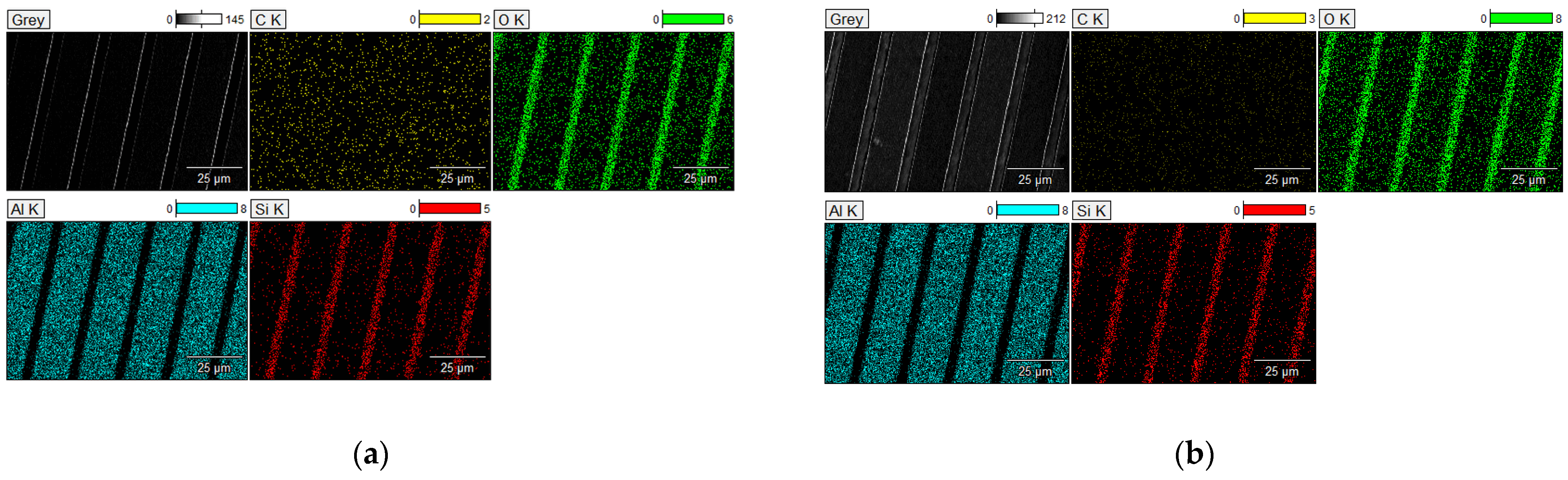
3.3. SEM and EDS Characterization of Activated and Non-Activated Samples

The activated and non-activated sensor surfaces, made out of aluminum thin film, were tested using scanning electron microscopy (SEM) and energy dispersive spectroscopy (EDS). The system used was an SEM FEI Scios2 Dual Beam System (Thermo Fisher Scientific, Waltham, MA, USA), Figure 6a,b.
Table 1 gives the percentage of counts for various elements found on the chip’s surface. It is interesting to note that the oxygen content increased after the process of activation. One possible scenario is that the aluminum oxide was removed from the digits’ surface, but the exposed activated aluminum attracted CO2 from the atmosphere, thus forming aluminum carbonate [46]. According to the chemical formula of aluminum carbonate, Al2(CO3)3 it is clear that each carbon atom will hold three oxygen atoms. In this scenario, we would expect that the increase in oxygen content on the chip’s surface would follow the increase in carbon content, but with a factor of three. From the data in Table 1, the percentage of counts associated with oxygen at the non-activated sample was 15.76%, while for the activated sample it was 18.35%. The difference is 2.59%. For carbon, the values were 1.549% for the non-activated and 2.401% for the activated sample. The difference is 0.852%. The ratio between the increase in oxygen and the increase in carbon is 2.59/0.852 = 3.03, which fits in the proposed scenario.

4. Discussion

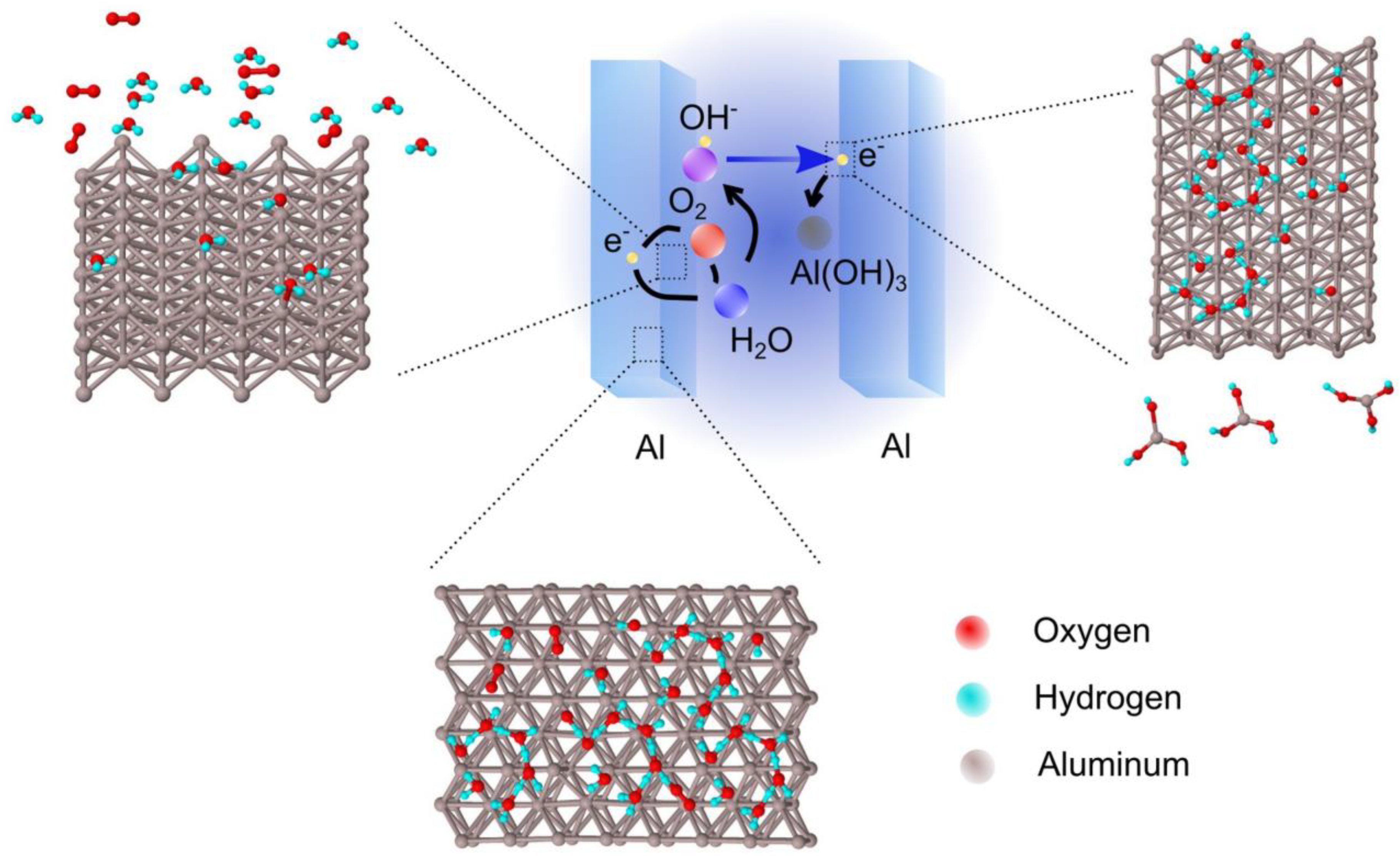
4.1. Electrochemical Activity of the Thin Film

The sensor based on activated aluminum adds electrochemical energy to the EM harvesting system by using the energy from the reaction of aluminum and water.
One option for energy addition comes from the general aluminum–air battery equations [47]:
Anode: Al(s) + 3OH (aq) → Al(OH)3(s) + 3e
Cathode: O2(g) + 2H2O(l) + 4e → 4OH (aq)
Overall: 4Al(s) + 3O2(g) + 6H2O(l) → 4Al(OH)3(s).
Another possibility is the reaction without involving O2 [48,49]:
Anode: Al(s) + 3OH(aq)→ Al(OH)3(s) + 3e
Cathode: 2H2O(l) + 2e → 2OH(aq) + H2(g)
Overall: 2Al(s) + 6H2O(l) → 2Al(OH)3(s) + 3H2(g).
The energy of the reaction is −300 kJ/mol. The theoretical electromotive force (EMF) of the reaction is 1.5 V. In this case, the reaction is occurring without oxygen, with the production of molecular hydrogen.
Figure 7 shows a possible mechanism responsible for energy addition to the EM harvesting for the sensor signal. The OH ions could be generated on both electrodes, since the sensor was made with mono-material electrodes. The OH ions can flow to the opposite electrode in order to react with aluminum, or they can come back to the same electrode and react with aluminum. This brings an uncertainty in the polarity of the signal because, at one moment, one electrode could play the role of an anode and, at another moment, the opposite electrode could become the anode. The accumulation of OH ions at one of the electrodes can produce an electric field strong enough to repel OH ions from another electrode. At any moment in time, one electrode could have significantly more OH ions than the other one. This produces the changeable polarity. In the case of coupling with EM harvesting, the changeable polarity can oscillate in the same frequency as the EM harvested signal. This can add energy to the EM harvesting. For this reason, EM harvesting plus electrochemical enhancement can increase the overall output from the sensor. More work will be needed in order to exactly quantify the ratio of energy added by electrochemistry with respect to EM harvesting.

4.2. Comparison with Other Respiration Monitoring Solutions Based on Humidity Detection

All solutions used for breath detection based on humidity measurements need to have a fast enough response to high humidity levels, in order to correctly monitor the respiration process. This essentially means that the rise-time and relaxation of the sensor needs to be around a few seconds. Many of these developments are compared in [3]. From the experiment presented in Figure 4, we see that our sensor has a rise-time and relaxation of 1 s or less, which makes it faster than most of the developments presented in [3].

4.3. Opportunity for Fully Independent Operation

The humidity sensor presented in this work is self-powered, meaning that the energy for its operation is harvested from the environment. This is yet not enough to make it fully independent, in the sense that the data needs to be transmitted, processed and displayed. This requires much more energy than it is possible to obtain through the EM harvesting presented here. One possible solution is to accumulate the harvested energy using large capacitors or other devices and subsequently use that energy for measuring humidity and also for data transmission. This will be the subject of our further work.
Supplementary material related to this article can be found online [50,51]. The supplementary material contains all figures in high resolution, raw data [50] and a short video [51] describing the process of measurements.

5. Conclusions

This work has shown that a self-powered, fully wearable, miniaturized breath-detection sensor is feasible, and can be realized by using the EM energy harvested from the human body. The key concept of the system operation is utilization of the interdigitated capacitor made out of an activated aluminum layer, which modulates the EM signal coming from the antenna that is harvesting EM energy from the environment. The system is so sensitive that even the human body can be used as an antenna, which is an advantage in the sense that no special devices or suits are needed. The unique concept of modulation of EM energy by humidity forms an exquisitely sensitive and versatile method for utilizing a low-power EM harvesting set-up as a humidity detector and thus, a wearable respiration monitoring system. The sensor fills the gap in self-powered human diagnostics, and provides an opportunity for other developments in wearable sensing. The system is capable of following human respiration in various situations with normal and fast breathing, including the cases of exercise and rest. This is the first development of this kind in the world. Further work will be in the direction of exactly quantifying the ratio of energy added by electrochemistry with respect to EM harvesting. For this purpose, materials other than aluminum will be tested in a similar experimental set-up.

Supplementary Materials

Supplementary material related to this article can be found online [50,51]. The supplementary material contains all figures in high resolution, raw data [50] and a short video [51] describing the process of measurements.

Author Contributions

Conceptualization, M.V.B. and M.S.; methodology, M.V.B. and M.S.; software, M.V.B. and M.S.; validation, M.V.B. and M.S.; formal analysis, M.V.B. and M.S.; investigation, M.V.B. and M.S.; resources, M.F., E.M., P.D.P. and J.N.S.; data curation, M.V.B. and M.S.; writing—original draft preparation, M.S.; writing—review and editing, M.V.B. and M.F.; visualization, M.V.B. and M.S.; supervision, M.S.; project administration, D.V.R.; funding acquisition, D.V.R. All authors have read and agreed to the published version of the manuscript.

Funding

This research was funded by the Ministry of Education, Science and Technological Development of the Republic of Serbia, grant number 451-03-68/2022-14/200026. The APC was funded by the Ministry of Education, Science and Technological Development of the Republic of Serbia, grant number 451-03-68/2022-14/200026.

Institutional Review Board Statement

Not applicable.

Informed Consent Statement

Not applicable.

Data Availability Statement

Not applicable.

Conflicts of Interest

The authors declare no conflict of interest. The funders had no role in the design of the study; in the collection, analyses, or interpretation of data; in the writing of the manuscript; or in the decision to publish the results.

References

  1. Dai, J.; Li, L.; Shi, B.; Li, Z. Recent progress of self-powered respiration monitoring systems. Biosens. Bioelectron. 2021, 194, 113609. [Google Scholar] [CrossRef]
  2. Beduk, T.; Durmus, C.; Hanoglu, S.B.; Beduk, D.; Salama, K.N.; Goksel, T.; Turhan, K.; Timur, S. Breath as the mirror of our body is the answer really blowing in the wind? Recent technologies in exhaled breath analysis systems as non-invasive sensing platforms. TrAC Trends Anal. Chem. 2021, 143, 116329. [Google Scholar] [CrossRef]
  3. Tai, H.; Wang, S.; Duan, Z.; Jiang, Y. Evolution of breath analysis based on humidity and gas sensors: Potential and challenges. Sensors Actuators B Chem. 2020, 318, 128104. [Google Scholar] [CrossRef]
  4. Güder, F.; Ainla, A.; Redston, J.; Mosadegh, B.; Glavan, A.; Martin, T.J.; Whitesides, G.M. Paper-Based Electrical Respiration Sensor. Angew. Chem. Int. Ed. 2016, 55, 5727–5732. [Google Scholar] [CrossRef] [Green Version]
  5. Sun, A.C.; Yao, C.; Venkatesh, A.G.; Hall, D.A. An efficient power harvesting mobile phone-based electrochemical biosensor for point-of-care health monitoring. Sensors Actuators B Chem. 2016, 235, 126–135. [Google Scholar] [CrossRef] [PubMed] [Green Version]
  6. Lv, C.; Hu, C.; Luo, J.; Liu, S.; Qiao, Y.; Zhang, Z.; Song, J.; Shi, Y.; Cai, J.; Watanabe, A. Recent Advances in Graphene-Based Humidity Sensors. Nanomaterials 2019, 9, 422. [Google Scholar] [CrossRef] [Green Version]
  7. Andrić, S.; Tomašević-Ilić, T.; Bošković, M.V.; Sarajlić, M.; Vasiljević-Radović, D.; Smiljanic, M.M.; Spasenović, M. Ultrafast humidity sensor based on liquid phase exfoliated graphene. Nanotechnology 2020, 32, 025505. [Google Scholar] [CrossRef] [PubMed]
  8. Peng, Y.; Zhao, Y.; Chen, M.-Q.; Xia, F. Research Advances in Microfiber Humidity Sensors. Small 2018, 14, e1800524. [Google Scholar] [CrossRef]
  9. Li, Y. Temperature and humidity sensors based on luminescent metal-organic frameworks. Polyhedron 2020, 179, 114413. [Google Scholar] [CrossRef]
  10. Malook, K.; Ali, M.; Ul-Haque, I. Elucidation of room temperature humidity sensing properties of Mn2O3 particles. Appl. Phys. A 2021, 127, 758. [Google Scholar] [CrossRef]
  11. Yu, S.; Zhang, H.; Zhang, J. Synthesis of high response gold/titanium dioxide humidity sensor and its application in human respiration. Ceram. Int. 2021, 47, 30880–30887. [Google Scholar] [CrossRef]
  12. Li, Z.; Wang, J.; Xu, Y.; Shen, M.; Duan, C.; Dai, L.; Ni, Y. Green and sustainable cellulose-derived humidity sensors: A review. Carbohydr. Polym. 2021, 270, 118385. [Google Scholar] [CrossRef] [PubMed]
  13. Tai, H.; Duan, Z.; Wang, Y.; Wang, S.; Jiang, Y. Paper-Based Sensors for Gas, Humidity, and Strain Detections: A Review. ACS Appl. Mater. Interfaces 2020, 12, 31037–31053. [Google Scholar] [CrossRef]
  14. Delipinar, T.; Shafique, A.; Gohar, M.S.; Yapici, M.K. Fabrication and Materials Integration of Flexible Humidity Sensors for Emerging Applications. ACS Omega 2021, 6, 8744–8753. [Google Scholar] [CrossRef] [PubMed]
  15. Shen, D.; Xiao, M.; Xiao, Y.; Zou, G.; Hu, L.; Zhao, B.; Liu, L.; Duley, W.W.; Zhou, Y.N. Self-Powered, Rapid-Response, and Highly Flexible Humidity Sensors Based on Moisture-Dependent Voltage Generation. ACS Appl. Mater. Interfaces 2019, 11, 14249–14255. [Google Scholar] [CrossRef]
  16. Kassal, P.; Steinberg, M.D.; Steinberg, I.M. Wireless chemical sensors and biosensors: A review. Sensors Actuators B Chem. 2018, 266, 228–245. [Google Scholar] [CrossRef]
  17. Xu, L.; Xuan, W.; Chen, J.; Zhang, C.; Tang, Y.; Huang, X.; Li, W.; Jin, H.; Dong, S.; Yin, W.; et al. Fully self-powered instantaneous wireless humidity sensing system based on triboelectric nanogenerator. Nano Energy 2021, 83, 105814. [Google Scholar] [CrossRef]
  18. Grattieri, M.; Minteer, S.D. Self-Powered Biosensors. ACS Sensors 2017, 3, 44–53. [Google Scholar] [CrossRef] [Green Version]
  19. Wen, Z.; Shen, Q.; Sun, X. Nanogenerators for Self-Powered Gas Sensing. Nano-Micro Lett. 2017, 9, 45. [Google Scholar] [CrossRef]
  20. Su, Y.; Chen, G.; Chen, C.; Gong, Q.; Xie, G.; Yao, M.; Tai, H.; Jiang, Y.; Chen, J. Self-Powered Respiration Monitoring Enabled By a Triboelectric Nanogenerator. Adv. Mater. 2021, 33, e2101262. [Google Scholar] [CrossRef]
  21. Wang, Y.; Dai, M.; Wu, H.; Xu, L.; Zhang, T.; Chen, W.; Wang, Z.L.; Yang, Y. Moisture induced electricity for self-powered microrobots. Nano Energy 2021, 90, 106499. [Google Scholar] [CrossRef]
  22. Fan, F.R.; Wu, W. Emerging Devices Based on Two-Dimensional Monolayer Materials for Energy Harvesting. Research 2019, 2019, 1–16. [Google Scholar] [CrossRef] [PubMed] [Green Version]
  23. Liu, X.; Gao, H.; Ward, J.E.; Liu, X.; Yin, B.; Fu, T.; Chen, J.; Lovley, D.R.; Yao, J. Power generation from ambient humidity using protein nanowires. Nature 2020, 578, 550–554. [Google Scholar] [CrossRef] [PubMed]
  24. Zhao, F.; Cheng, H.; Zhang, Z.; Jiang, L.; Qu, L. Direct Power Generation from a Graphene Oxide Film under Moisture. Adv. Mater. 2015, 27, 4351–4357. [Google Scholar] [CrossRef] [PubMed]
  25. Chen, Y.; Kuang, Y.; Shi, D.; Hou, M.; Chen, X.; Jiang, L.; Gao, J.; Zhang, L.; He, Y.; Wong, C.-P. A triboelectric nanogenerator design for harvesting environmental mechanical energy from water mist. Nano Energy 2020, 73, 104765. [Google Scholar] [CrossRef]
  26. Shao, C.; Gao, J.; Xu, T.; Ji, B.; Xiao, Y.; Gao, C.; Zhao, Y.; Qu, L. Wearable fiberform hygroelectric generator. Nano Energy 2018, 53, 698–705. [Google Scholar] [CrossRef]
  27. Chang, T.-H.; Peng, Y.-W.; Chen, C.-H.; Wu, J.-M.; Hwang, J.-C.; Gan, J.-Y.; Lin, Z.-H. Protein-based contact electrification and its uses for mechanical energy harvesting and humidity detecting. Nano Energy 2016, 21, 238–246. [Google Scholar] [CrossRef]
  28. Li, L.; Hao, M.; Yang, X.; Sun, F.; Bai, Y.; Ding, H.; Wang, S.; Zhang, T. Sustainable and flexible hydrovoltaic power generator for wearable sensing electronics. Nano Energy 2020, 72, 104663. [Google Scholar] [CrossRef]
  29. Zhang, Z.; Li, X.; Yin, J.; Xu, Y.; Fei, W.; Xue, M.; Wang, Q.; Zhou, J.; Guo, W. Emerging hydrovoltaic technology. Nat. Nanotechnol. 2018, 13, 1109–1119. [Google Scholar] [CrossRef]
  30. Xiao, Y.; Shen, D.; Zou, G.; Wu, A.; Liu, L.; Duley, W.W.; Zhou, Y.N. Self-powered, flexible and remote-controlled breath monitor based on TiO2nanowire networks. Nanotechnology 2019, 30, 325503. [Google Scholar] [CrossRef]
  31. Bošković, M.V.; Sarajlić, M.; Frantlović, M.; Smiljanić, M.M.; Randjelović, D.V.; Zobenica, K.C.; Radović, D.V. Aluminum-based self-powered hyper-fast miniaturized sensor for breath humidity detection. Sensors Actuators B Chem. 2020, 321, 128635. [Google Scholar] [CrossRef]
  32. Bošković, M.; Šljukić, B.; Radović, D.V.; Radulović, K.; Rafajilović, M.R.; Frantlović, M.; Sarajlić, M. Full-Self-Powered Humidity Sensor Based on Electrochemical Aluminum–Water Reaction. Sensors 2021, 21, 3486. [Google Scholar] [CrossRef] [PubMed]
  33. Li, Y.; Lu, J. Metal–Air Batteries: Will They Be the Future Electrochemical Energy Storage Device of Choice? ACS Energy Lett. 2017, 2, 1370–1377. [Google Scholar] [CrossRef]
  34. Zhang, X.; Grajal, J.; López-Vallejo, M.; McVay, E.; Palacios, T. Opportunities and Challenges of Ambient Radio-Frequency Energy Harvesting. Joule 2020, 4, 1148–1152. [Google Scholar] [CrossRef]
  35. Cambero, E.V.V.; da Paz, H.P.; da Silva, V.S.; Consonni, D.; Capovilla, C.E.; Casella, I.R.S. A revised methodology to analyze the rectenna power conversion efficiency based on antenna/rectifier interface losses. AEU-Int. J. Electron. Commun. 2021, 134, 153686. [Google Scholar] [CrossRef]
  36. Song, C.; Huang, Y.; Zhou, J.; Zhang, J.; Yuan, S.; Carter, P. A High-Efficiency Broadband Rectenna for Ambient Wireless Energy Harvesting. IEEE Trans. Antennas Propag. 2015, 63, 3486–3495. [Google Scholar] [CrossRef] [Green Version]
  37. Lopez, O.L.A.; Clerckx, B.; Latva-Aho, M. Dynamic RF Combining for Multi-Antenna Ambient Energy Harvesting. IEEE Wirel. Commun. Lett. 2021, 11, 493–497. [Google Scholar] [CrossRef]
  38. Assimonis, S.D.; Fusco, V.; Georgiadis, A.; Samaras, T. Efficient and Sensitive Electrically Small Rectenna for Ultra-Low Power RF Energy Harvesting. Sci. Rep. 2018, 8, 15038. [Google Scholar] [CrossRef] [PubMed] [Green Version]
  39. Lee, H.; Sriramdas, R.; Kumar, P.; Sanghadasa, M.; Kang, M.G.; Priya, S. Maximizing power generation from ambient stray magnetic fields around smart infrastructures enabling self-powered wireless devices. Energy Environ. Sci. 2020, 13, 1462–1472. [Google Scholar] [CrossRef]
  40. Gao, M.; Wang, P.; Jiang, L.; Wang, B.; Yao, Y.; Liu, S.; Chu, D.; Cheng, W.; Lu, Y. Power generation for wearable systems. Energy Environ. Sci. 2021, 14, 2114–2157. [Google Scholar] [CrossRef]
  41. Tian, X.; Lee, P.M.; Tan, Y.J.; Wu, T.L.Y.; Yao, H.; Zhang, M.; Li, Z.; Ng, K.A.; Tee, B.C.K.; Ho, J.S. Wireless body sensor networks based on metamaterial textiles. Nat. Electron. 2019, 2, 243–251. [Google Scholar] [CrossRef]
  42. Kravchenko, O.; Semenenko, K.; Bulychev, B.; Kalmykov, K. Activation of aluminum metal and its reaction with water. J. Alloy. Compd. 2005, 397, 58–62. [Google Scholar] [CrossRef]
  43. Trenikhin, M.V.; Kozlov, A.G.; Nizovskii, A.I.; Drozdov, V.A.; Lavrenov, A.V.; Bubnov, A.V.; Finevich, V.P.; Duplyakin, V.K. Activated aluminum: Features of production and application in the synthesis of catalysts for pertochemistry and oil processing. Russ. J. Gen. Chem. 2007, 77, 2320–2327. [Google Scholar] [CrossRef]
  44. STPS1150. 150 V, 1 A Power Schottky Rectifier. Available online: https://www.st.com/en/diodes-and-rectifiers/stps1150.html#documentation (accessed on 20 September 2022).
  45. Canepa, P.; Hanson, R.M.; Ugliengo, P.; Alfredsson, M. J-ICE: A new Jmol interface for handling and visualizing crystallographic and electronic properties. J. Appl. Crystallogr. 2010, 44, 225–229. [Google Scholar] [CrossRef]
  46. National Center for Biotechnology Information. “PubChem Compound Summary for CID 10353966, Aluminum carbonate” PubChem. Available online: https://pubchem.ncbi.nlm.nih.gov/compound/Aluminum-carbonate (accessed on 12 September 2022).
  47. Tamez, M.; Yu, J.H. Aluminum—Air Battery. J. Chem. Educ. 2007, 84, 1936A. [Google Scholar] [CrossRef]
  48. Pyun, S.-I.; Moon, S.-M. Corrosion mechanism of pure aluminium in aqueous alkaline solution. J. Solid State Electrochem. 2000, 4, 267–272. [Google Scholar] [CrossRef]
  49. Godart, P.; Fischman, J.; Seto, K.; Hart, D. Hydrogen production from aluminum-water reactions subject to varied pressures and temperatures. Int. J. Hydrogen Energy 2019, 44, 11448–11458. [Google Scholar] [CrossRef]
  50. Bošković, M.; Milinković, E.; Radović, D.V.; Stevanović, J.; Sarajlić, M. Self-powered wearable breath-monitoring sensor based on electrochemically modulated electromagnetic energy harvesting, Supplementary data 1. Mendeley Data, 2022; V1. [Google Scholar] [CrossRef]
  51. Sarajlic, M.; Bošković, M. Self-powered wearable breath-monitoring sensor based on electrochemically modulated electromagnetic energy harvesting, Supplementary data 2. Mendeley Data, 2022; V1. [Google Scholar] [CrossRef]
Figure 1. Fabricated sensor: (a) Schematic illustration of the fabrication process: (i) Untreated silicon wafer; (ii) Thermal oxidation; (iii) Aluminum thin film deposition by sputtering; (iv) Photoresist spin coating; (v) Optical lithography by direct laser writing; (vi) Aluminum wet etching; (vii) Photoresist removal. (b) Design of the chip on the housing, made by using 3D software (FreeCAD). (c) Photograph of the finished sensor mounted on a TO-8 housing and wire bonded; the diameter of the TO-8 housing is 13 mm, while the size of the diced chip is 3.8 mm. (d) Photograph of the finished sensor (scale bar is 5 mm). (e) Zoom into the sensor chip with a single battery, magnified by 3D stereo microscope (scale bar is 1 mm). (f) Zoom into the sensor digits magnified by optical microscope (scale bar is 0.1 mm). (g) Micrograph of the sensor surface by which the width of the digits was estimated at 0.015 mm, while the clearance between the digits was estimated at 0.005 mm (scale bar is 0.04 mm).
Chemosensors 11 00051 g001
Figure 2. Concept of the sensor operation: (a) EM harvesting by rectenna: basic structure; (b) The modified rectenna used in this work for humidity and breath detection. The signal that is harvested by the antenna is modulated by humidity using an interdigitated capacitor made out of activated aluminum.
Chemosensors 11 00051 g002
Figure 3. (a) Illustration of the breath humidity sensor powered by EM energy harvested from the human body; (b) Equivalent schematic of the sensor together with the antenna, rectifier and voltmeter; (c) Rectification of the voltage obtained by EM energy harvesting using a wire connected to the building foundation (left) and histogram of the recorded signal (right); (d) Rectification of the voltage coming from the EM energy harvested from the human body using an antistatic wrist strap (left) and histogram of the recorded signal (right); (e) Direct breath-blow on the sensor surface and signal from the voltmeter. The EM harvesting was realized by using a wire connected to the building foundation; (f) Direct breath-blow on the sensor surface and the signal from the voltmeter. The EM energy was sourced from the human body by using an antistatic wrist strap. The ambient humidity during all measurements was 35% RH.
Chemosensors 11 00051 g003
Figure 4. The sensor test on breathing with a mask: (a) The mask used for the breathing test with the sensor connected to the EM harvesting using a wristband. The sensor fixture (inset); (b) Schematic of the sensor test with mask breathing using building foundation as an EM source. The maximum signal was up to 400 mV; (c) Breath speed 17 cpm; (d) 22 cpm; (e) 52 cpm; (f) Schematic of the sensor test with mask breathing using human body as an EM source. The maximum signal was up to 80 mV; (g) Breath speed 19 cpm; (h) 22 cpm; (i) 52 cpm.
Chemosensors 11 00051 g004
Figure 5. The use of the sensor with human body EM harvesting in the case of cycling exercise: (a,b) The volunteer with antistatic wrist strap carrying out cycling exercise; (c) The output of the sensor for load 3 on exercise bike and the speed of 21 km/h; (d) The output of the sensor for load 8 on exercise bike and the speed of 27 km/h. The load increased from 1 to 8. The pronounced noise during cycling is the consequence of the EM interference coming from the exercise bike, since the bike used EM-based load exerted on a driver.
Chemosensors 11 00051 g005
Figure 6. SEM EDS characterization: (a) Non-activated Al surface; (b) Activated Al surface.
Chemosensors 11 00051 g006
Figure 7. Illustration of the electrochemical process described by Equations (1)–(3). Incoming electrons on one of the electrodes will take part in the reaction between water and oxygen. As a result of this reaction, the hydroxyl group (OH) is formed and diffuses through the water until it reaches the opposite electrode. At the opposite electrode, the hydroxyl group reacts with aluminum, thus forming aluminum hydroxide. At the same time, electrons are released on the aluminum electrode. The electrons drift through outer circuitry. Images of aluminum crystal lattice and molecules were generated using the software Jmol [45].
Chemosensors 11 00051 g007
Table 1. Results of EDS scan over the surface visible in Figure 6a,b.
Non-ActivatedActivated
ElementCountsPercentage Counts [%]CountsPercentage Counts [%]
C32301.54950892.401
O32,86915.7638,89218.35
Al157,69475.64152,96072.17
Si14,6667.03514,9857.071
Total208,459100211,926100
Disclaimer/Publisher’s Note: The statements, opinions and data contained in all publications are solely those of the individual author(s) and contributor(s) and not of MDPI and/or the editor(s). MDPI and/or the editor(s) disclaim responsibility for any injury to people or property resulting from any ideas, methods, instructions or products referred to in the content.

