Article

Effects of Acidic Solution on the One-Step Electrodeposition of Prussian Blue Nanocrystals on Screen-Printed Carbon Electrodes Modified with Magnetite Nanoparticles

Department of Applied Chemistry, National Chi Nan University, Puli 545, Nantou Hsien, Taiwan
*
Author to whom correspondence should be addressed.
Chemosensors 2022, 10(8), 325; https://doi.org/10.3390/chemosensors10080325
Submission received: 24 June 2022 / Revised: 4 August 2022 / Accepted: 9 August 2022 / Published: 11 August 2022
(This article belongs to the Collection Electrochemical Biosensors for Medical Diagnosis)

Abstract

:
This study investigated the electrochemical synthesis of Prussian blue (PB) nanocrystals on a screen-printed carbon electrode (SPCE) modified with a thin film of magnetite nanoparticles (nano-Fe3O4) in aqueous mixture solutions of potassium hexacyanoferrate(III) and different kinds of acids. The generated PB nanocrystals exhibited varied voltammetric responses that are highly related to the characteristics and properties of acids in the mixture solution. Interestingly, in the presence of glyphosate as an organic acid, surface magnetite nanoparticles were occluded within electrogenerated Prussian blue nanocubes (PBNC), which are characterized by scanning electron microscopy (SEM), X-ray photoelectron spectroscopy (XPS), attenuated total reflection Fourier-transform infrared spectroscopy (ATR-FTIR), and cyclic voltammetry (CV). Furthermore, the possible reaction mechanism for the formation of PBNC is proposed in this study. The obtained PBNC was also evaluated as an electrocatalyst of hydrogen peroxide and applied to the detection of glyphosate.

1. Introduction

With the considerable progress of nanoscience and nanotechnology, magnetic nanomaterials have attracted broad attention due to their electric, magnetic, chemical, optical and mechanical properties [1,2,3,4,5]. The literature has shown their potential applications in the forensic [1], synthetic [2] biomedical [3], catalytic [4] and environmental [5] fields as a result of their unique features. Magnetite nanoparticles (nano-Fe3O4) are one important kind of magnetic nanomaterials that possess many novel characteristics such as high crystalline structure, large specific surface area, excellent biocompatibility, favorable biodegradability, low cytotoxicity, facile surface functionalization and efficient biomolecule binding. Hence, nano-Fe3O4 are essentially investigated in energy harnessing, analytical techniques, environmental remediation and biomedical applications [6,7,8,9,10].
Prussian blue (PB) is a type of self-assembled coordination compound of iron(III) hexacyanoferrate(II) with a 3D crystalline framework structure of Fe3+, Fe2+, and bridging cyano groups [11,12,13,14]. Owing to PB’s excellent biocompatibility, remarkable photothermal effect, multiple enzyme-like characteristics and excellent redox property, synthetic approaches have been proposed to meet the demands and applications in various fields such as adsorption, catalysis, ion batteries, electrochromic displays, chemical sensing, enzymatic biosensors, biomedicine, and photomagnets [11,12,13,14]. PB is known as an electrochromic material; the colorless Prussian white (PW) is the fully reduced state, the Prussian yellow (PY) is the fully oxidized state, and the Berlin green (BG) is the intermediate form of PB and PY. Conversion between PW/PB and PB/PY is reversible upon potential modulation. The redox reactions of soluble PB (KFeFe(CN)6) and insoluble PB (Fe4[Fe(CN)6)]3) have been proposed as Equations (1)–(4), respectively [11].
KFe III Fe II ( CN ) 6 + e + K + K 2 Fe II Fe II ( CN ) 6
KFe III Fe II ( CN ) 6 Fe III Fe III ( CN ) 6 + e + K +
Fe III 4 [ Fe II ( CN ) 6 ] 3 + 4 e + 4 K + K 4 Fe II 4 [ Fe II ( CN ) 6 ] 3
Fe III 4 [ Fe II ( CN ) 6 ] 3 + 3 X Fe III 4 [ Fe III ( CN ) 6 ] X 3 + 3 e
The PB precipitate can be prepared by wet chemical routes via stirring an aqueous mixture solution of iron(III) salt (such as FeCl3) and potassium hexacyanoferrate(II) (K4Fe(CN)6). Alternatively, a PB product can be produced through a reaction between iron(II) salt (such as FeCl2) and potassium hexacyanoferrate(III) (K3Fe(CN)6) [14]. The product has two forms, soluble PB and insoluble PB, depending on the excess reagent in the preparation step [14]. The electrochemical synthesis of PB coatings has been immobilized at various conductive electrode substrates, and the electrolytic systems are usually a highly acidic HCl solution with two iron sources, Fe3+ ions and Fe(CN)63− [11].
Different from the classical method in which the formation of PB proceeds with two iron sources [11,12,13,14], there are reports on the synthesis of Prussian blue nanoparticles (PBNP) where K3Fe(CN)6 was used as the only iron source [15,16,17,18,19]. The obtained products showed diverse shapes, sizes, and morphologies, greatly affecting their multifunctional properties and potential applications. In 2012, Ming et al. prepared PBNP by heating a mixture of K3Fe(CN)6 and poly (vinylpyrrolidone) (PVP) in an HCl solution (pH < 2) at 80 °C for 20 h [15]. The formation of PBNP is associated with the chemical processes of acidic dissolution of Fe(CN)63− in releasing Fe3+ ions and a reduction reaction with PVP in producing Fe2+ ions. The reaction between Fe(CN)63− and Fe2+ further forms PBNP with PVP coating, which prevents the products from aggregations by binding to the iron ions of the PBNP. The obtained PBNP exhibits various sizes (20–200 nm) and shapes (cube and rectangle), depending on the reaction parameters [15]. Yang’s work demonstrated an electrochemical synthesis of PBNP at a Pt disk electrode in an acidic solution containing only K3Fe(CN)6 [19]. The results show that under a potential where an electrochemical reduction of Fe(CN)63− occurs, the reduced product Fe(CN)64− will dissociate in acidic conditions to release Fe2+ ions. Then, the free Fe2+ ions will coordinate with Fe(CN)64− to generate PW nanoparticles, which convert reversibly to PBNP as electrode potential is stepped to a more positive value [19].
Reports show that magnetite nanoparticles have been employed as a support material for forming a PBNP coating based on a solid/liquid route by stirring a nano-Fe3O4 dispersed solution containing diluted HCl, K3Fe(CN)6, and FeCl3 [17]. Due to adsorption effects, the two iron precursors were assembled to achieve a PBNP shell on the nano-Fe3O4 core; the obtained core-shell nanostructured product was found to be applicable to the electrocatalytic reduction of H2O2 [17]. Alternatively, magnetite nanoparticles-modified glassy carbon electrodes could be employed as an iron ion source that induces PBNP growth at an electrode surface via potential cycling in an acidic phosphate buffer solution (pH 2.0) containing Fe(CN)63− [16]. It was inferred that due to the instability in the acidic solution, free iron ions (Fe3+ and Fe2+) leach from a nano-Fe3O4-coated glassy carbon electrode and then react with Fe(CN)63− (or Fe(CN)64−) ions to form PBNP that shows cuboid and 3D polygon shapes with a wide size distribution (50–120 nm) [16]. The deposition of PBNP at the carbon paste electrode was also achieved through an electrochemical reaction between iron species encapsulated in multi-walled carbon nanotubes and Fe(CN)64− ions in an aqueous KCl solution, where no acid was mentioned in the work [18].
Glyphosate (N-(phosphonomethyl)glycine) is an organophosphate post-emergent herbicide, categorized as a carcinogen for humans [20,21]. Glyphosate is a polyprotic acid, and the zwitterion of glyphosate (Figure S1) possesses high acidity given that the acid dissociation constants (pKa) are 2.23 (carboxylate), 5.46 (2nd phosphonic), and 10.14 (amine) [22]. There is increasing use of glyphosate in food and non-food cropping systems due to its highly effective, broad-spectrum action to block the enzymatic functions in plants, leading to the reduction of annual weed between crop plants and the eventual consequences for facilitating the harvest [20,21]. Meanwhile, the glyphosate contamination in foods and the environment has raised concerns about the harmful effects on human society. Analytical methods for the quantitative determination of glyphosate have been reported [22,23,24,25,26,27,28,29,30], and some methods require highly-skilled operators, expensive instruments, and complicated sample treatments that restrict practical application [22,23,24]. Electrochemical methods are cost-effective alternative techniques. Though electrochemical determination of glyphosate has been developed previously [25,26,27,28,29,30], the preparation procedures of the modified electrodes are tedious. A recent report demonstrated a selective and efficient electrochemical glyphosate sensor that uses gold nanoelectrode arrays without any analyte derivatization or electrode functionalization [31].
The electrochemical formation of PBNP is very convenient and time-saving, and the characteristics of the obtained products depend on the source of the two iron precursors. Herein, a facial heterogeneous synthesis of PBNP has been developed on a magnetite nanoparticles-modified electrode, which is electrochemically treated in acidic KCl solutions containing K3Fe(CN)6. The obtained PBNP exhibited different sizes, shapes, surface morphology and electrochemical activities, depending on the features of the co-existing acids. Worthy of note, for the first time, glyphosate was utilized in this study as an organic acid, producing uniform PB nanocubes (PBNC) (Scheme 1). A plausible PBNC growth mechanism is being discussed; preliminary works on the application of the as-prepared PBNC show their potential for electrocatalytic H2O2 reduction (and also oxidation). Moreover, glyphosate detection based on the voltammetric technique is proposed.

2. Experimental

2.1. Reagents

Glyphosate, potassium hexacyanoferrate(III) (K3Fe(CN)6), ferric chloride hexahydrate (FeCl3·6H2O), ferrous chloride tetrahydrate (FeCl2·4H2O), ammonia solution, aminomethylphosphonic acid (AMPA) and dimethylformamide (DMF) were purchased from Acros Organics. The chemicals obtained were used without further purification. The supporting electrolyte was 0.1 M KCl solution prepared using deionized water from a Milli-Q ultrapure water system. The phosphate buffer solutions (PBS) were prepared with 0.1 M of potassium dihydrogen phosphate and then adjusted to the desired pH using small amounts of concentrated HCl or KOH.

2.2. Instruments

Cyclic Voltammetry (CV) was performed with a CHI electrochemical workstation (CH Instruments, model CHI-621C). Cyclic voltammograms are plotted according to the IUPAC (International Union of Pure and Applied Chemistry) convention. The three-electrode system consists of a screen-printed carbon electrode (SPCE, 5.0 mm in diameter, Zensor R&D, Taichung, Taiwan), a home-made Ag|AgCl|KCl (sat.) reference electrode, and a platinum counter electrode. All potentials were reported with respect to this reference electrode. Most of the experiments were carried out at room temperature (25 ± 2 °C). High temperature experiments were accomplished by simply immersing the electrochemical cell in a small hot water bath to maintain the desired elevated temperatures. The pH values were measured with a Thermo Scientific Orion pH meter (Model 420) and a Mettler Toledo pH electrode (Model Inlab 439/120).
Fourier-transform infrared spectra (FTIR) were recorded using a PerkinElmer frontier spectrophotometer for Fe3O4 nanoparticle/KBr pellet samples. The percent transmittance was recorded in a spectral range from 4000 cm−1 to 400 cm−1. Attenuated total reflection Fourier-transform infrared (ATR-FTIR) measurements were carried out for modified electrode surface using the same instrument equipped with an ATR ZnSe crystal (from 4000 cm−1 to 650 cm−1). The shape and size of nano-Fe3O4 were characterized by transmission electron microscope (TEM) with a high-resolution transmission electron microscope (JEOL, JEM-2010) operating at an accelerating voltage of 120 kV. The test sample was a thin film prepared by placing a drop of dispersed nano-Fe3O4 solution onto a copper grid coated with a carbon film. A Hitachi S-4700I filed-emission scanning electron microscope (FE-SEM) was used to characterize the electrode surface morphology. X-ray photoelectron spectroscopy (XPS) was investigated using a PHI 5000 VersaProbe/PHI Quantera SXM instrument with an AlKαX source to identify and quantify elemental compositions for the electrode surface.

2.3. Synthesis of Fe3O4 Nanoparticles

Magnetic nano-Fe3O4 were prepared by a simple chemical coprecipitation with chloride salts of Fe(III) and Fe(II) at a ratio of 2:1 [17]. Briefly, 100 mL of aqueous solution containing 2.90 g of FeCl3·6H2O (10.7 mmol) and 1.06 g of FeCl2·4H2O (5.3 mmol) was prepared. The mixture was heated to 80 °C under N2 atmosphere, and then 10 mL of ammonia solution (25%, v/v) was added dropwise under stirring for 60 min. The black color magnetic nanoparticles were precipitated, and separated from the solution using an external magnet, followed by washing three times with deionized water and 95% ethanol, respectively. The powder was then dried in vacuum at 60 °C for 24 h. The TEM image of the product is shown in the supplementary material. As shown in Figure S2, the bare nano-Fe3O4 are spherical with an average diameter of 14.9 nm.

2.4. Preparation of Nano-Fe3O4 Modified Electrodes

The screen-printed carbon electrodes modified with nano-Fe3O4 were obtained by a two-step procedure. First, bare electrode was treated by continuous cycling in a potential window of −0.6 V to +1.0 V at a scan rate of 0.1 Vs−1 in pH 7 phosphate buffer solutions (PBS) for three cycles to remove some organic binder. Second, 6.0 μL of the as-prepared nano-Fe3O4 dispersion solution (1 mg/1 mL DMF) was dropped on a treated SPCE, and then dried under an infrared lamp. The obtained modified electrode was labeled SPCE/nano-Fe3O4.

3. Results and Discussion

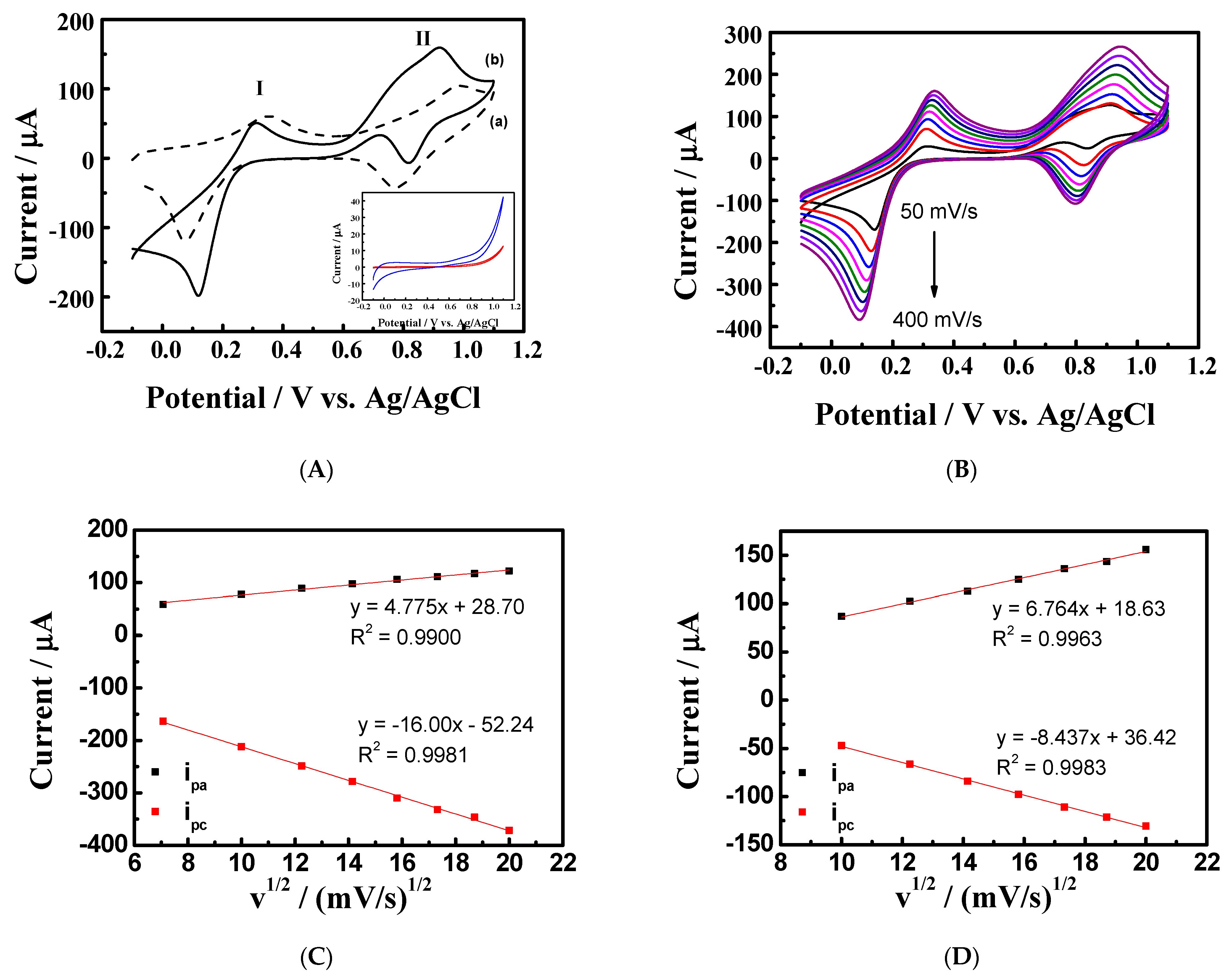
3.1. Electrochemical Study of SPCE/Nano-Fe3O4 in a Mixture Solution Containing Hexacyanoferrate(III) and Glyphosate

Four acidic mixture solutions were used as electrolytic solutions in this study. The composition and pH value of each electrolytic solution are shown in Table 1. The cyclic voltammetric responses of SPCE/nano-Fe3O4 in the electrolytic solutions are compared in Figure 1. The starting potential was +0.6 V, reversed at −0.1 V, and then ended at +0.6 V (defined as one CV cycle). All the consecutive multi-voltammetric curves showed a redox couple around 0.2 V with different extents of distortion. Furthermore, the peak currents apparently increased as the number of cycles increased, especially in Solutions I, II, and III.
As indicated for the first cycle in Figure 1A, in which the electrolytic solution contained 1.0 mM K3Fe(CN)6, 0.1 M KCl, and 1.0 mM glyphosate, a reduction peak appeared at +0.188 V, and an oxidation peak appeared at +0.282 V. The redox couple K3Fe(CN)6 is responsible for this redox peak being the electroactive compound in the examined potential window. The peak currents increase, and the cathodic peak shapes become sharper as the number of cycles increases, suggesting that an adsorption process occurs at the electrode/electrolyte interface. In addition, the peak-to-peak potential separation increases after each CV cycle, revealing that the electrochemical adsorption slows down gradually. After 10 CV cycles, the subsequent electrode was removed from Solution I, washed with deionized water, and then transferred into a 0.1 M KCl solution to record cyclic voltammetric responses (Figure 2A), obviously indicating that the PB film was generated. There are two pairs of redox peaks; the redox peak (I) occurs at E1/2 = 0.210 V (Epa1 = 0.294 V; Epc1 = 0.126 V), and the redox peak (II) occurs at E1/2 = 0.868 V (Epa2 = 0.923 V; Epc2 = 0.812 V). The redox peak (I) arises from an electron transfer between PB and PW, corresponding to the redox reaction of a high-spin system Fe3+/2+. The redox peak (II) is attributed to an electron transfer between PB and PY due to the redox reaction of low spin Fe(CN)63−/4− [11]. Figure 3A shows the representative SEM images (50,000× magnification) of the topmost modified electrode surfaces obtained after the 10 CV cycles in Solution I. The large quantity of compact crystalline cubes with an average size of 76.0 nm (RSD = 0.12%) completely cover the underlying nano-Fe3O4 and exceed its diameter. Figure 3E displays the SEM images of SPCE/nano-Fe3O4 as a reference. A spherical-shaped nano-Fe3O4 is observed. The result proved that Prussian blue nanocubes (PBNC) could be modified onto the electrode after the electrochemical treatment. Subsequently, the obtained modified electrode was labeled SPCE/nano-Fe3O4/PBNC.
It is considered that the nano-Fe3O4 not only acts as active substrates for PBNC growth but also provides iron ions, Fe3+ and Fe2+, responsible for PBNC deposition. In order to investigate the contribution of the nano-Fe3O4 to the electrochemical reactions in Solution I, cyclic voltammetry is carried out with a bare SPCE (without nano-Fe3O4 loading). As indicated in Figure S3A, a typical redox peak of Fe(CN)63−/Fe(CN)64− appeared at E1/2 = 0.225 V (Epa = 0.264 V; Epc = 0.186 V), and there were no changes in the voltammograms during the successive 10 cycles. After the potential scanning, the treated electrode showed a very small redox peak at about 0.2 V (Figure S3A’ and inset), which would be the adsorption of Fe(CN)63− on the SPCE carbon particles. Another possibility is the formation of a very small amount of PBNP due to the inherent Fe impurities present in the carbon paste for the mass production of the commercial SPCE. A previous study has revealed that commercial 3D-printed graphene-polylactic acid filament contains iron impurity, the iron ion source that generates PB [32]. The decomposition of Fe(CN)63− that produces the Fe3+ ion is assumed to be negligible for the time span of the CV experiments. In other words, the formation of PBNC from K3Fe(CN)6 as a single iron source is excluded under the given experimental conditions. Thus, the comparison between the results obtained from SPCE/nano-Fe3O4 and bare SPCE indicates that the coated nano-Fe3O4 serves as the iron ion sources and supports the growth of PBNC.
In order to elucidate the effects of chemical reagents in the electrolytic solution on the observed electrodeposition reactions, the electrochemical experiments using SPCE/nano-Fe3O4 were conducted again. However, the electrolytic solution contained only two components, either 0.1 M KCl and 1.0 mM glyphosate (Figure S3B) or 0.1 M KCl and 1.0 mM K3Fe(CN)6 (Figure S3C). The resultant electrodes (Figure S3B’,C’) proved that PBNC could not be deposited on the electrode without the presence of K3Fe(CN)6 and glyphosate, although the same potential scanning was employed. Furthermore, to understand the chemical structure of glyphosate as an influencing factor in PBNC formation, its metabolite AMPA was used instead of glyphosate in Solution I. As indicated in Figure S3D, the redox peak of Fe(CN)63−/Fe(CN)64− changed slightly, and the resultant electrode showed no discernible redox peak of PBNC after 10 CV cycles (Figure S3D’). It is noted in this test that although the precursors nano-Fe3O4 and K3Fe(CN)6 were present in the electrochemical system, there is no apparent PB growth in the presence of AMPA. Thus, for the electrolytic solution where SPCE/nano-Fe3O4 is examined, the co-existence of K3Fe(CN)6 and glyphosate is needed for PBNC production, and the chemical feature of glyphosate certainly plays an essential role in PBNC formation.

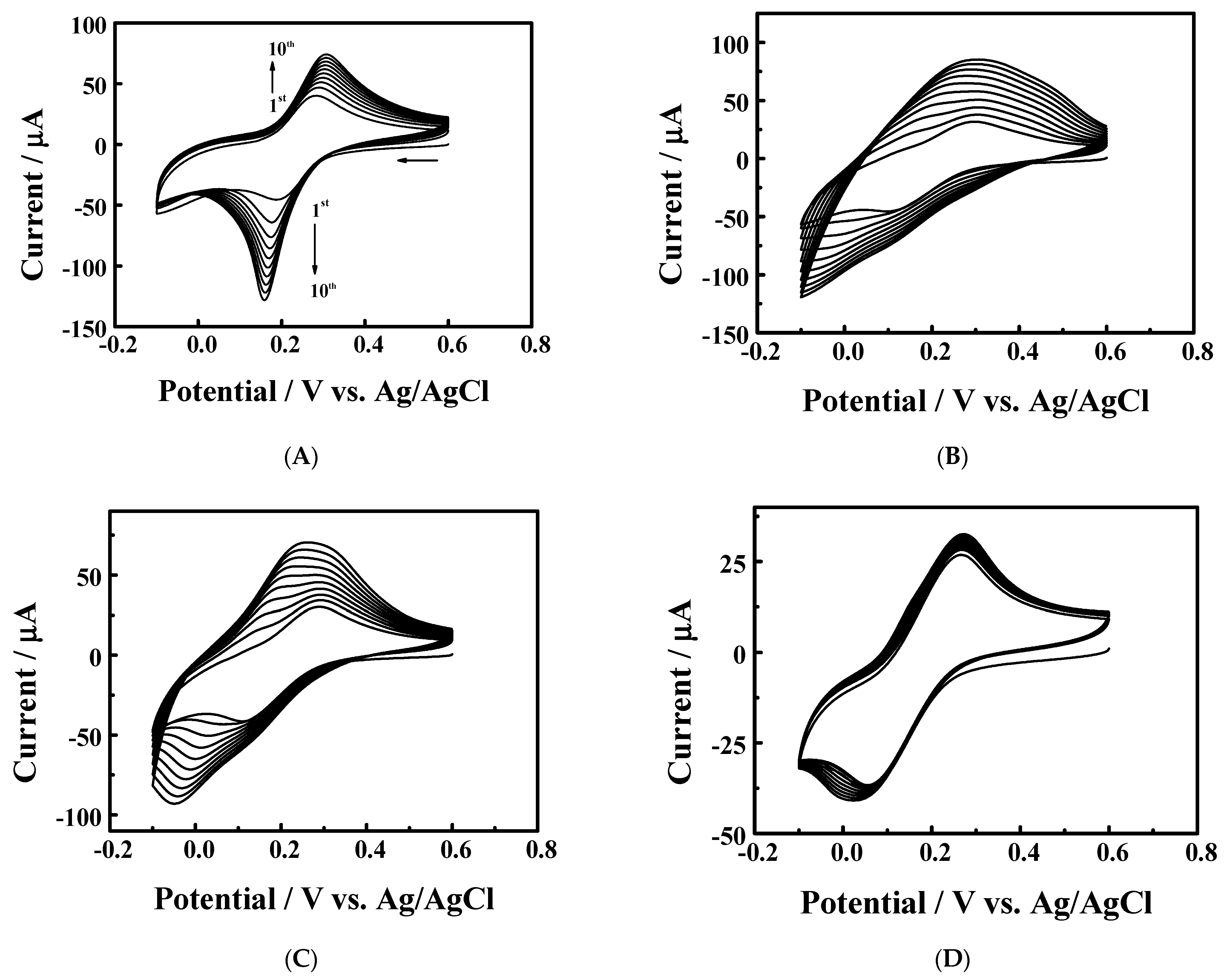
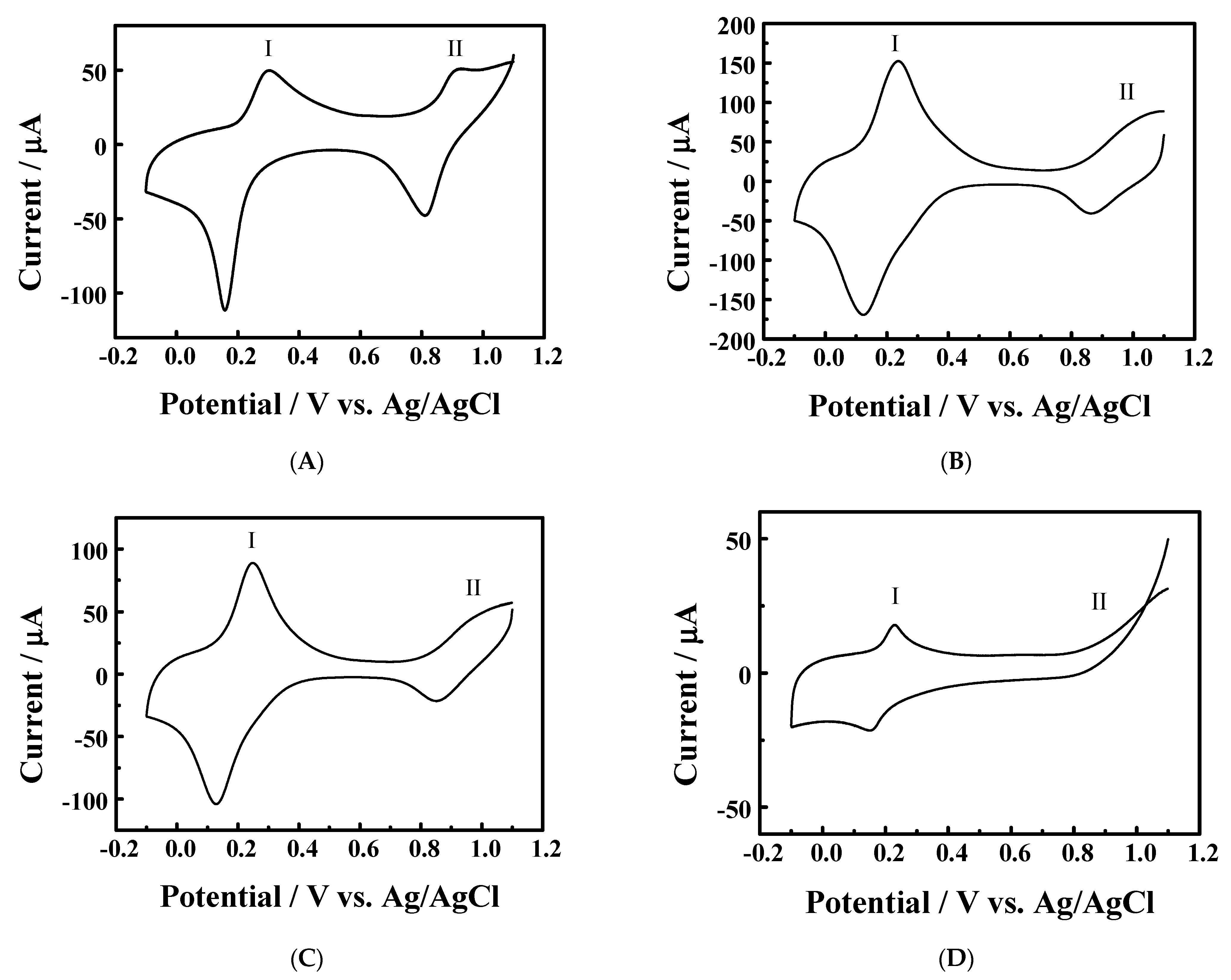
3.2. The Effects of Acids on the Electrochemical Formation of PBNC

In exploring the acidic effects of electrolytic solution on the PBNC formation, the same electrochemical deposition processes were performed in Solution II, where 1.0 mM HCl was present. Figure 1B shows the voltammograms, where a considerable CV peak shape broadening can be observed: (1) a large peak-to-peak potential separation is observed for the first cycle (Epa = 0.300 V; Epc = 0.104 V); (2) throughout the 10 CV cycles, a broad redox peak (or wave) between +0.6 V and −0.1 V increased. The electrochemical treatment also led to the formation of a Prussian blue modified electrode. As shown in Figure 2B, the redox peak of PB/PW is very broad and high, while that of PB/PY is weaker. The subsequent SEM images are presented in Figure 3B, revealing a high density of PB cubes (average size = 73.2 nm, RSD = 0.10%) and some polygons with varied sizes covered on the electrode surface. Notably, similar CV and SEM results were obtained when the 1.0 mM HCl in Solution II was replaced with 1.0 mM H3PO4 (not shown).
The same electrochemical deposition approach was conducted in Solution III containing 1.0 mM citric acid. As can be observed, the multi-cyclic voltammograms (Figure 1C) showed a similar pattern, in which the current responses increase as the number of CV cycles increased. The obtained PBNP showed clear redox couples (Figure 2C). The corresponding SEM images (Figure 3C) showed the formation of PB nanocrystals with a smaller average size of 58.2 nm (RSD = 0.11%) than those obtained from Solution I and Solution II. However, the formation of PBNP is not facilitated in Solution IV, where 1.0 mM acetic acid was used. As shown in Figure 1D, there was only a slight change for the multiple CV scanning, the resultant PBNP exhibited small redox currents (Figure 2D), and the obtained PBNP was very small (Figure 3D). The cumulative charge (Q) transferred for the reduction of PB to PW can be obtained based on the cathodic peak from 0.4 V to −0.1 V (Figure 2) by integrating current to time (the X-axis is converted to time). The amount of PBNP per geometric area was in the order of Solution II (8.25 nmol/cm2) > Solution III (4.15 nmol/cm2) > Solution I (3.34 nmol/cm2) > Solution IV (0.25 nmol/cm2). The values can be estimated from the charge using the formula Q/nFA, where n is the number of electrons (n = 1, Equation (1)), F is the Faraday constant (96,485 C/mol), and A is the surface area of the electrode (0.196 cm2).
Since the nano-Fe3O4 coatings participated in the PB formation, the above results reflected the different stability of the nano-Fe3O4 in the four electrolytic solutions. A previous report also indicated that nano-Fe3O4 are very stable in water, but subject to dissolution in an acidic solution due to protonation of surface oxygen [33]. This phenomenon weakens neighboring iron-oxygen bonds and leads to the release of lattice iron ions (Fe3+ and Fe2+) from the surface sites [33]. Thus, an aqueous solution that favors lattice iron ions released from nano-Fe3O4 results in a more probable formation of PBNP in the presence of Fe(CN)63−. Considering the acidity of the above four mixture solutions, Solution II has the smallest pH value (3.07), therefore it facilitates the PBNP growth. On the other hand, Solution IV has the highest pH value of 4.95, limiting the PBNP formation. In addition, the free nano-Fe3O4 in Solution II is subject to easier dissolution than the protected nano-Fe3O4 due to being in contact with organic acids. Organic compounds, such as dimercaptosuccinic acid, 3-aminopropyltriethoxysilane, and citric acid, have been used as surface modifiers to slow the iron ion release rate [34]. The resultant PBNP showed that fewer PBNP were obtained from Solution I (pH 3.12) than Solution III (pH 3.38), possibly due to a stronger iron-chelation ability of glyphosate than that of citric acid. The higher the interaction of the functional groups with nano-Fe3O4, the fewer the released iron ions, resulting in less PBNP formation in the presence of Fe(CN)63−. Indeed, glyphosate has high affinities for iron binding and shows larger stability constants with Fe(II) compared to citric acid (106.9 vs. 106.1) [20].
Another interesting aspect is the voltammetric curves for the above works. In the electrodeposition of PBNC in Solution I, the voltammetric curves have features contrasting greatly with the others from Solutions II, III, and IV. In Solution I, where glyphosate is present, the repetitive current responses are the sharpest among the above four solutions (Figure 1A). Furthermore, the obtained PBNC also exhibits the sharpest redox peaks (Figure 2A). The produced PB nuclei units are possibly aligned and grown in a more orderly fashion in Solution I, leading to good product quality and showing improved electron-transfer kinetics and homogeneity (Figure 3A), compared with those from the Solutions II, III, and IV. Meanwhile, the difference in the obtained products represents the combined results of the selective etching by acid types and precipitation processes. The synergic effects of the acidity and chelation ability of glyphosate may mostly contribute to the good morphology and electron transfer kinetics.
To analyze the growth of PBNC obtained from Solution I, the SEM images of the obtained electrode at different synthesis stages were monitored. Figure 4A shows that at the early electrodeposition stage (starting potential +0.6 V, ending potential +0.25 V), there were nanoscale clusters (small bright dots) acting as PB nuclei randomly distributed on the nano-Fe3O4 concave surface. As shown in Figure 4B, crystallization occurred as the ending potential moved to a more negative value at −0.1 V. The crystals then continued to grow and became a multi-crystalline structure after 1 (Figure 4C) and 2 CV cycles (Figure 4D). As the reaction proceeded, clear cubic shapes were formed after 3 (Figure 4E) and 5 CV cycles (Figure 4F), possibly by an interface-driven growth mechanism [35]. In contrast to the observed truncated crystals, a high-quality PBNC product was found after 10 CV cycles (Figure 3A), which showed a smooth surface with visible intercrystalline lines.
Thus, the reaction mechanism is proposed accordingly. As shown in Equation (5), the acidity from the acids (HX) causes a proton-promoted dissolution process from the solid/solution interface to the underlying nano-Fe3O4, especially in inorganic acids (HCl and H3PO4). By introducing an organic acid, such as glyphosate or citric acid, which has a strong surface interaction with the surface nano-Fe3O4 (noted as nano-Fe3O4....HX), the release of iron ions can be slowed down. The redox reactions of the iron species are presented as Equations (6) and (7). The iron precursors at the electrolyte/electrode interface may either be the oxidized form or the reduced form; their concentration ratio is controlled by the electrode potential. The half-wave potential (E1/2) of Fe(CN)63−/Fe(CN)64− is +0.225 V, while that of Fe3+/Fe2+ is +0.482 V and shifts negatively to +0.476 V in the presence of glyphosate (Figure S4). Equations (8)–(10) describe the precipitation reactions that occur instantaneously between these iron precursors. The supply of the iron precursors is controlled by the acid dissolution reactions and the electrode potential, affecting the growth of the external PBNC. Equations (11) and (12) are the redox reactions of PW/PB and PB/PY, respectively. In short, the efficient formation of PBNC nanostructure is mainly attributed to the electrochemical approach that modulate the concentration of iron precursors and the multiple functional groups of glyphosate that control the release of iron ions and act as nucleation sites.
nano- Fe 3 O 4 + HX Fe 3 + + Fe 2 + + nano- Fe 3 O 4 · · · HX
Fe 3 + + e Fe 2 +
Fe ( CN ) 6 3 + e Fe ( CN ) 6 4
Fe 3 + + Fe ( CN ) 6 4 PB
Fe 2 + + Fe ( CN ) 6 3 PB
Fe 2 + + Fe ( CN ) 6 4 PW
PB + e PW
PY + e PB
HX = inorganic or organic acids

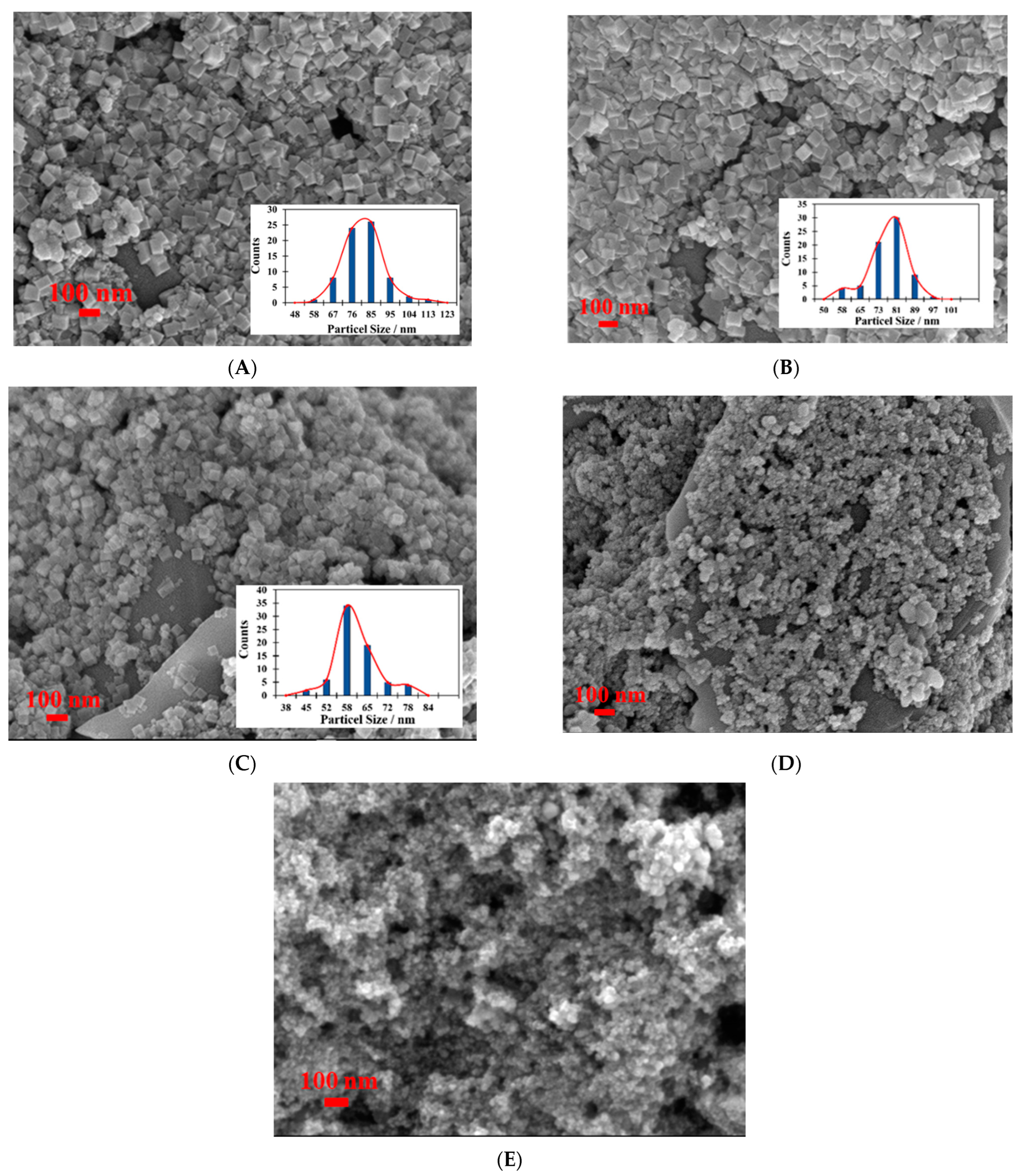
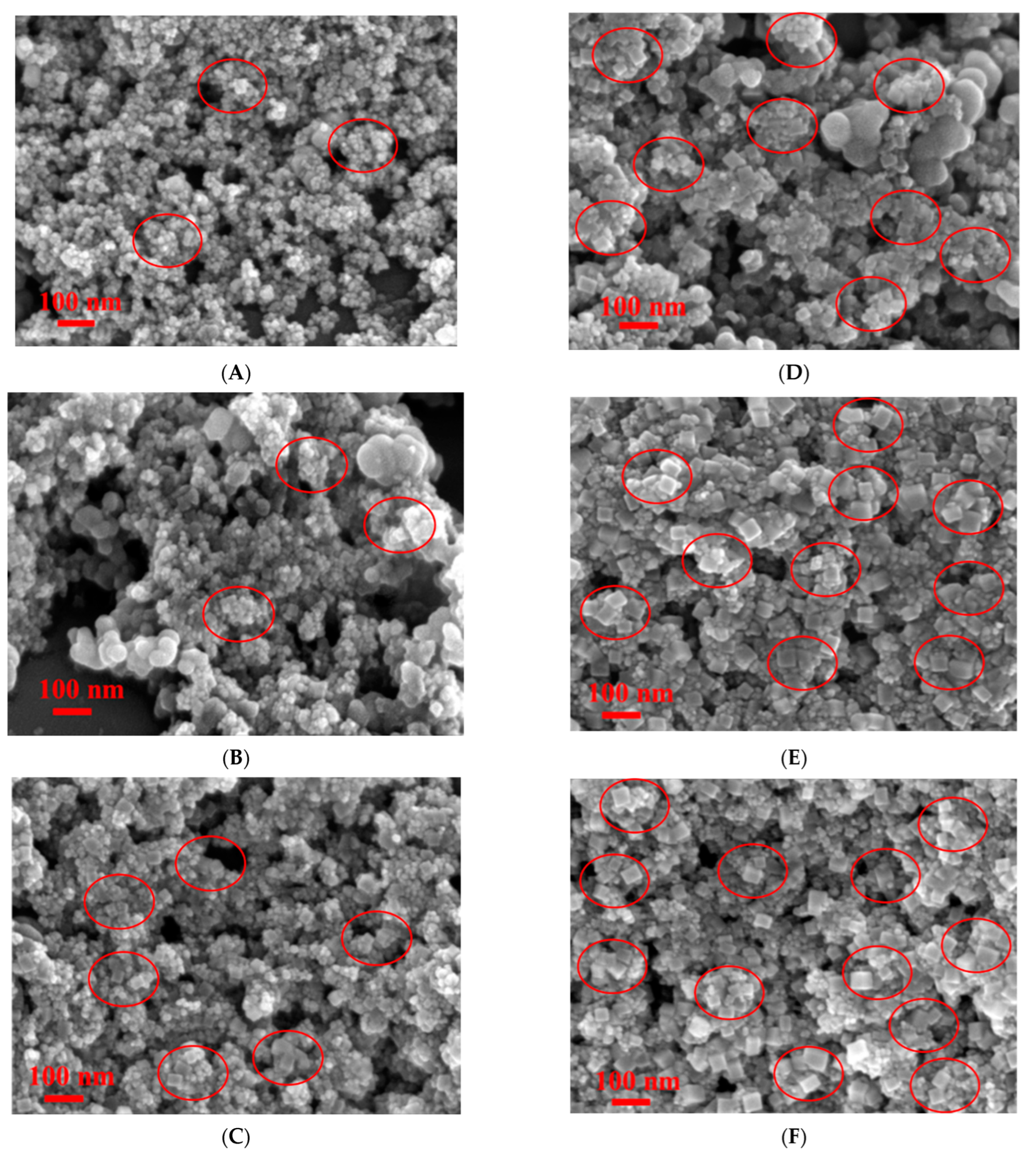
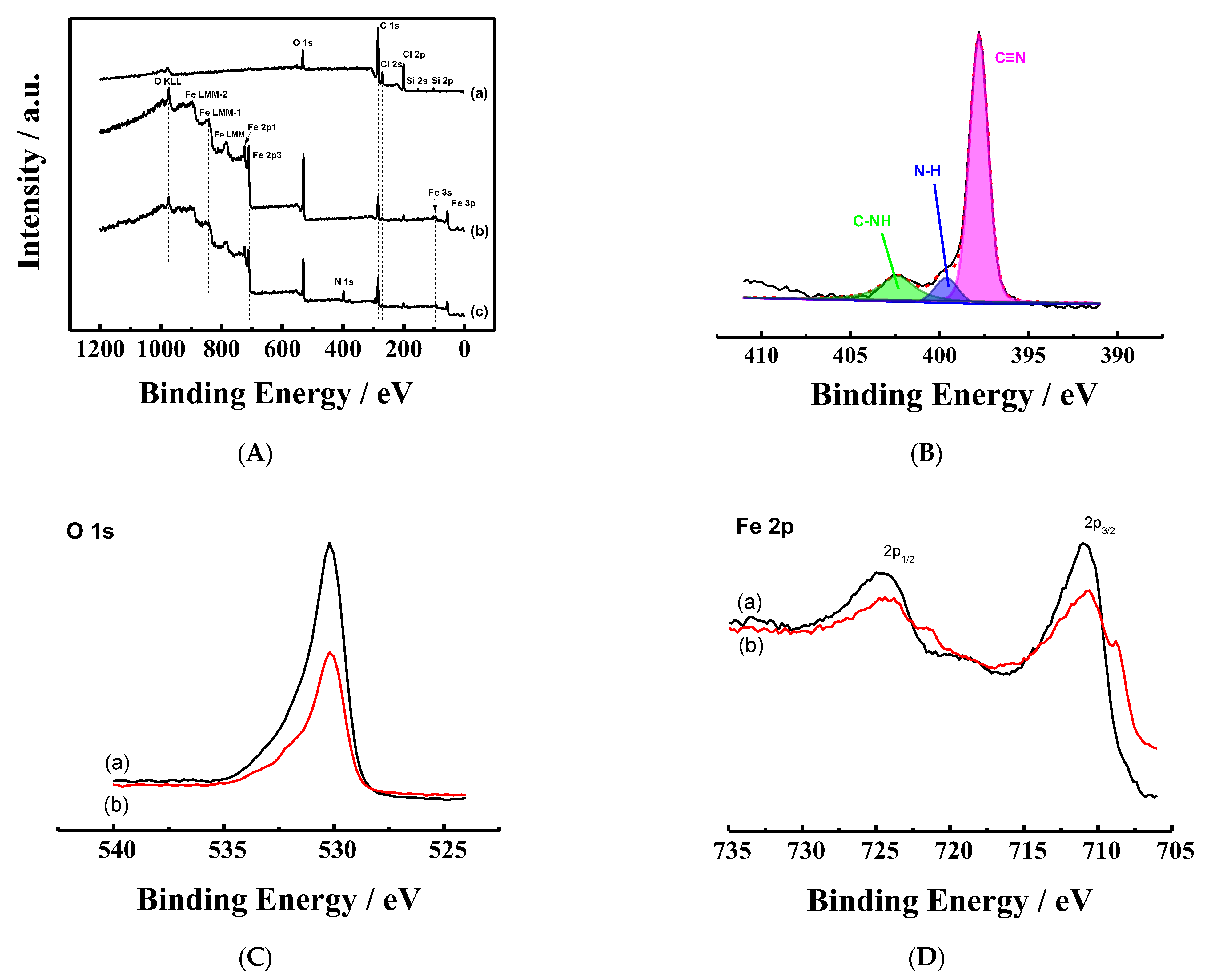
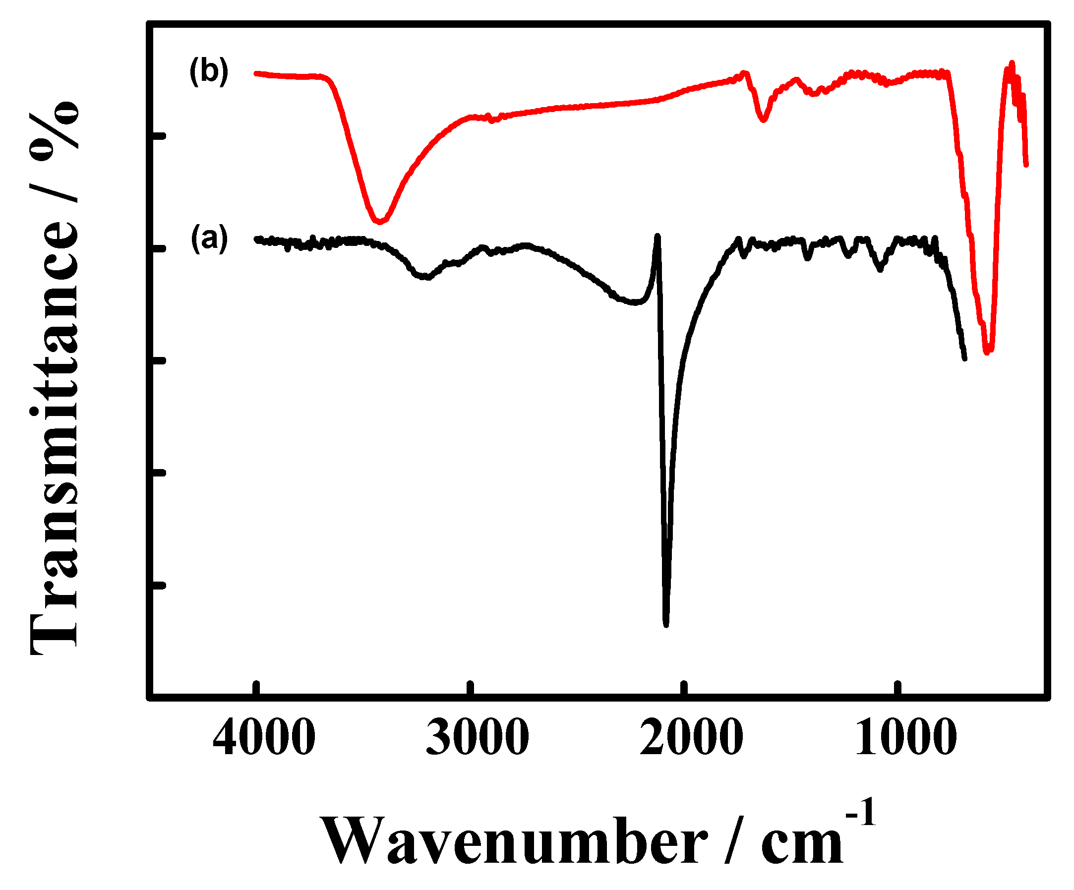
3.3. Spectral Characterization of SPCE/Nano-Fe3O4/PBNC

The relative composition of the electrode surface constituents after PBNC layer modification in Solution I was further examined. The XPS spectra of SPCE/nano-Fe3O4/PBNC showed a nitrogen element N 1s peak at 397.8 eV (Figure 5A, Spectrum c) [17], while no such peak can be observed for the bare SPCE and SPCE/nano-Fe3O4. The N atom ratio was calculated as 10.2%. The XPS narrow-scan spectra in the region of 390–410 eV were further analyzed through peak resolution and fitting (Figure 5B). The deconvoluted XPS spectrum of the asymmetric N peak suggested the presence of three chemical states at 402.5, 399.8, and 397.8 eV binding energy attributed to the C–NH, N–H and –C≡N signals [17,36], respectively. The strong –C≡N signal confirms the deposition of PB, while the small peaks of C–NH and N–H arise from glyphosate. Thus, it is suggested that a small quantity of glyphosate is also trapped as nanohybrid composites. The oxygen and iron elements of the two electrodes, SPCE/nano-Fe3O4 and SPCE/nano-Fe3O4/PBNC, were further compared by XPS analysis. Figure 5C showed that SPCE/nano-Fe3O4/PBNC exhibited a lower intense O 1s peak at 530.2 eV [7], compared with that of SPCE/nano-Fe3O4. This is due to the release of oxygen from coated Fe3O4 during the PB formation. The Fe 2p spectra of the two electrodes were shown in Figure 5D, and every electrode demonstrated two peaks near 709.9 eV and 724.5 eV, corresponding to Fe 2p3/2 and Fe 2p1/2 [7], respectively. In the spectrum of SPCE/nano-Fe3O4/PBNC, distinct shoulder peaks near 708.8 eV and 721.4 eV (Figure 5D, Spectrum b) were observed, which resembled those of the reported PB [37].
The absorption spectrum of SPCE/nano-Fe3O4/PBNC presented a different pattern compared to nano-Fe3O4 powder. The FTIR spectrum obtained from nano-Fe3O4 exhibited an intense peak at 584.7 cm−1 attributed to the stretching of the Fe–O bond; a broad band centered at 3437.5 cm−1 was attributable to the stretching and bending vibration of the hydroxyl groups (Figure 6, Spectrum b). Meanwhile, the ATR-FTIR spectrum of SPCE/nano-Fe3O4/PBNC showed a new strong peak at 2083.8 cm−1 arising from the stretching vibration of the Fe(III)–CN–Fe(II) structure (Figure 6, Spectrum a), pointing out the PB formation [16,17,18].
The above spectral results verify the successful PB coating on the electrode surface. Thus, the electrochemical deposition is a more convenient and effective method for obtaining a composite of PBNC shell and nano-Fe3O4 core than the conventional chemical synthesis. For a typical chemical synthesis of PB shell using the Fe3O4 core as the Fe3+ ion source, the reaction is usually carried out by mechanically stirring a mixture of Fe3O4 nanoparticles and K3Fe(CN)6 in a diluted HCl solution for 30 min, and the obtained particles will show irregular shapes and unclear edge [17,18]. Hu et al. reported that PB nanocubes could be achieved chemically using organic molecule-modified iron oxide nanoparticles (Fe3O4 and γ-Fe2O3), and the produced PB nanocubes have a wide size distribution with a diameter of about 80–150 nm [34]. As far as the current knowledge is concerned, there is no report on the direct electrodeposition of PBNC onto the electrode surface modified with nano-Fe3O4, which acts as a source of Fe3+ ion equivalents. This work reveals that a compact PBNC coating is achieved unconventionally and more effectively than in previous works.

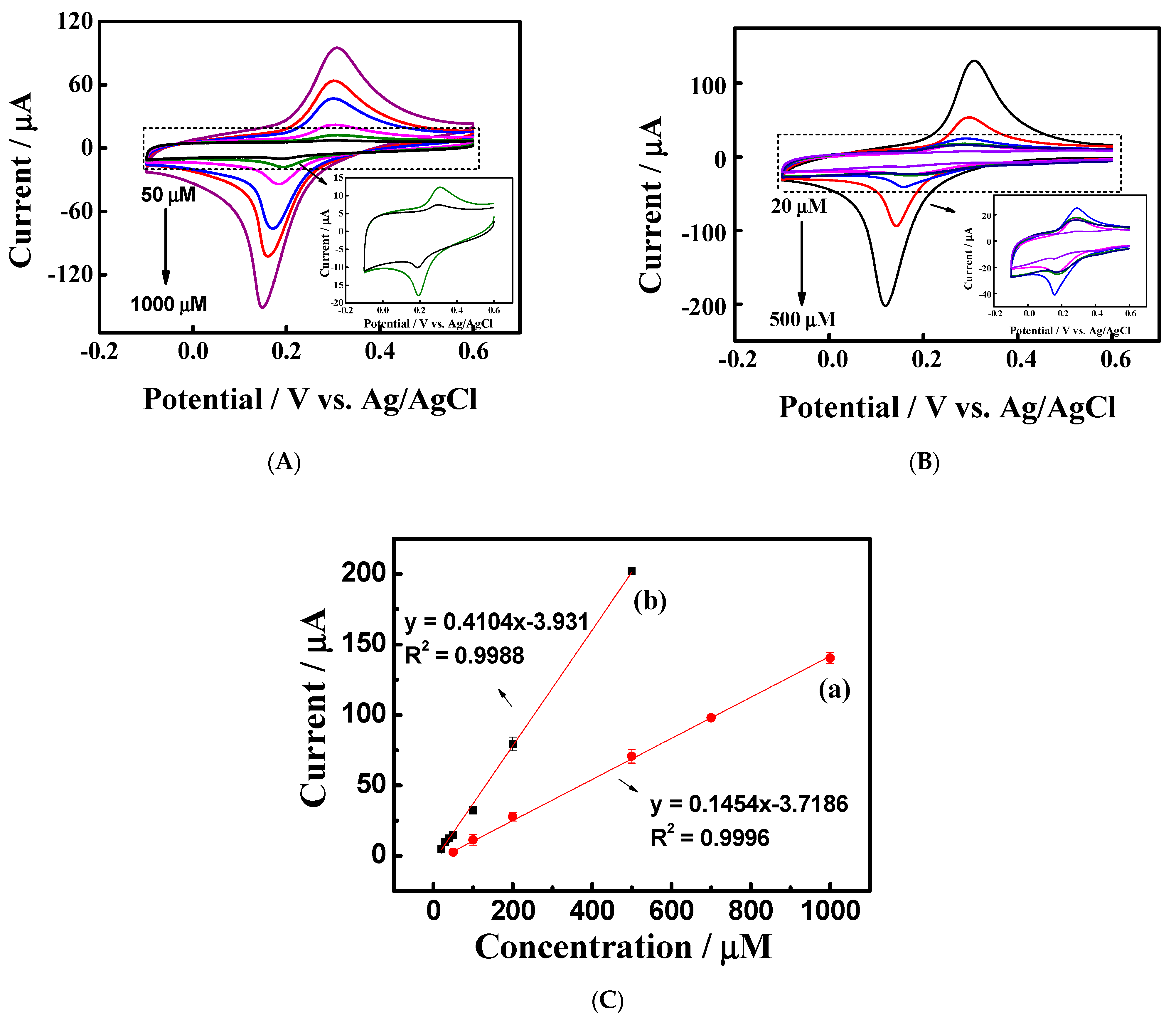
3.4. The Electrochemical Application of SPCE/Nano-Fe3O4/PBNC

The electrocatalytic activity of the electrodeposited PBNC was evaluated by studying the cyclic voltammetric responses in the presence of H2O2 [16]. As shown in Figure 7A, in the less positive potential region where redox peak I appeared, an increased cathodic peak current at 0.119 V was observed for the 3.0 mM H2O2 solution (Curve b), contrasting to Curve a in the absence of H2O2. Redox peak II was observed in the positive-going potential scan. The voltammetric peak for H2O2 oxidation took place at a lower onset potential of +0.648 V, reached a maximum at 0.922 V, and then declined to the end of the potential region, showing a significant increase in oxidation current responses. The current changes of bare SPCE and SPCE/Fe3O4 in the same H2O2 solution were also examined; however, few responses were observed (Figure 7A, inset). The higher electrocatalytic performance of H2O2 at the PBNC-modified electrode can be attributed to the advances in the electron transfer of PBNC compared to the bare electrode and nano-Fe3O4–modified electrode. The cyclic voltammetric responses of the 3.0 mM H2O2 solution were further examined at different scan rates in the range of 50–400 mVs−1; the peak currents increased with the increasing scan rates (Figure 7B). The cathodic and anodic peak currents for the electrocatalytic reactions were analyzed separately, and both currents were found to be linearly proportional to the square root of the scan rate, as for redox peak I (Figure 7C) and redox peak II (Figure 7D). The results indicated that both the catalytic H2O2 reduction reaction and catalytic H2O2 oxidation reaction are diffusion-controlled processes.
Another application is to develop an electrochemical assay for the indirect determination of glyphosate. With the impact of glyphosate on the formation of stable PBNC on nano-Fe3O4, it is expected that the amounts of PBNC formation must be a function of the glyphosate concentration. As shown in Figure 8A, visible redox peaks originating from PB/PW were observed in the glyphosate concentrations ranging from 50 μM to 1000 μM. Nonetheless, it is challenging to find this redox peak in a more diluted solution at an ambient temperature. In a mixture solution containing 10 μM glyphosate, the pH value reaches 5.3. This weak acidity limits the initial iron release from magnetite nanoparticles, thereby hindering the formation of PB. The cathodic peak currents of the PB/PW were analyzed further. At an ambient temperature, a linear relationship with glyphosate concentration from 50 μM to 1000 μM was given by the equations: Y (μA) = 0.1454 X (μM) + 3.7186 (R2 = 0.9996) (Figure 8C, Curve a). An increased temperature in the electrolytic solution is supposed to affect the dissolution of nano-Fe3O4, increasing the PB formation. Results have shown that for 200 μM glyphosate mixture solution at 70 °C, there is a three-fold increase in the current signal of PB/PW compared to the one at ambient temperature. As shown in Figure 8B, higher temperatures resulted in a dramatic increase of the PB/PW redox peak current, while the redox peak potential was essentially unchanged. The cause for such an increase in the peak current is mainly due to the greater growth of PB in an electrolytic solution maintained at above ambient temperatures. At 70 °C, a linear equation was given for glyphosate concentration ranging from 20 μM to 500 μM: Y (μA) = 0.4104 X (μM) − 3.931 (R2 = 0.9988) (Figure 8C, Curve b). The proposed assay is not sensitive to glyphosate lower than 20 μM in the current study. However, the present work has opened a new methodology to detect glyphosate simply and economically. It looks promising to use the other metal oxide nanomaterials instead of magnetite nanoparticles in generating PB analogs [12] to achieve the analytical purpose.

4. Conclusions

This work demonstrated a double-precursors synthesis of the Prussian blue nanoparticle using nano-Fe3O4-modified screen-printed carbon electrodes and K3Fe(CN)6 in the acidic electrolyte solution. The merit of this work lies in that the heterointerfaces of PB nanocrystal and nano-Fe3O4 can be produced efficiently and conveniently by a facile electrodeposition approach. The chemical features of the added acids, including the acid dissociation property and coordination ability, control the product properties, such as size, morphology and electrochemical activity. We have produced a stable PBNC shell and nano-Fe3O4 core composites using glyphosate as an organic acid. The as-prepared PBNC exhibits electrocatalytic activity towards H2O2 reduction and oxidation. Moreover, the redox peak of PB/PW can serve as a signal for the indirect detection of glyphosate at an ambient temperature and high temperature. Further investigations of this electrodeposition approach may open up new opportunities for electrocatalytic and sensing applications.

Supplementary Materials

The following are available online at https://www.mdpi.com/article/10.3390/chemosensors10080325/s1, Figure S1: The acid dissociation constants of glyphosate and the related species. Figure S2: (A) TEM image of nano-Fe3O4 at 400,000× magnification. (B) The corresponding particle size distribution graphs (N = 60). Figure S3: (A) Cyclic voltammograms of bare SPCE in solution I for 10 cycles. Cyclic voltammograms of SPCE/nano-Fe3O4 in a mixture solution of (B) 1.0 mM glyphosate and 0.1 M KCl (C) 1.0 mM K3Fe(CN)6 and 0.1 M KCl solution (D) 1.0 mM K3Fe(CN)6, 0.1 M KCl and 1.0 mM AMPA for 10 cycles. (A’–D’) Cyclic voltammogram of the resultant electrode, which was obtained after the potential scanning in the corresponding solution and then transferring to 0.1 M KCl. Scan rate = 0.1 Vs−1. Figure S4: Cyclic voltammograms of bare GCE in 0.1 M KCl solution containing 0.2 mM FeCl3 and (a) 0 mM, (b) 0.05 mM, (c) 0.1 mM, (d) 0.2 mM glyphosate. Scan rate = 0.005 Vs−1.

Author Contributions

M.-M.T.: Investigation, Methodology. Y.-L.S.: Validation, Project administration. S.-H.C.: Conceptualization, Funding acquisition, Supervision, Writing—original draft, Writing—review & editing. All authors have read and agreed to the published version of the manuscript.

Funding

This work was supported by the Ministry of Science and Technology, Taiwan under grants MOST 109-2113-M-260-005.

Institutional Review Board Statement

Not applicable.

Informed Consent Statement

Not applicable.

Data Availability Statement

Data is contained within the article or supplementary materials.

Acknowledgments

The authors gratefully acknowledge the service provided by The Office of Research and Development, National Chung Hsing University, Taiwan.

Conflicts of Interest

The authors declare that they have no conflict of interest.

References

  1. Nadar, S.S.; Kelkar, R.K.; Pise, P.V.; Patil, N.P.; Patil, S.P.; Chaubal-Durve, N.S.; Bhange, V.P.; Tiwari, M.S.; Patil, P.D. The Untapped Potential of Magnetic Nanoparticles for Forensic Investigations: A Comprehensive Review. Talanta 2021, 230, 122297–122313. [Google Scholar] [CrossRef]
  2. Gebre, S.H. Recent Developments in the Fabrication of Magnetic Nanoparticles for the Synthesis of Trisubstituted Pyridines and Imidazoles: A Green Approach. Synth. Commun. 2021, 51, 1669–1699. [Google Scholar] [CrossRef]
  3. Gul, S.; Khan, S.B.; Rehman, I.U.; Khan, M.A.; Khan, M.I. A Comprehensive Review of Magnetic Nanomaterials Modern Day Theranostics. Front. Mater. 2019, 6, 179. [Google Scholar] [CrossRef]
  4. Neamtu, M.; Nadejde, C.; Hodoroaba, V.-D.; Schneider, R.J.; Verestiuc, L.; Panne, U. Functionalized Magnetic Nanoparticles: Synthesis, Characterization, Catalytic Application and Assessment of Toxicity. Sci. Rep. 2018, 8, 6278–6288. [Google Scholar] [CrossRef]
  5. Mohammed, L.; Gomaa, H.G.; Ragab, D.; Zhu, J. Magnetic Nanoparticles for Environmental and Biomedical Applications: A Review. Particuology 2017, 30, 1–14. [Google Scholar] [CrossRef]
  6. Ashraf, M.; Khan, I.; Usman, M.; Khan, A.; Shah, S.S.; Khan, A.Z.; Saeed, K.; Yaseen, M.; Ehsan, M.F.; Tahir, M.N.; et al. Hematite and Magnetite Nanostructures for Green and Sustainable Energy Harnessing and Environmental Pollution Control: A Review. Chem. Res. Toxicol. 2020, 33, 1292–1311. [Google Scholar] [CrossRef] [PubMed]
  7. Saiphaneendra, B.; Saxena, T.; Singh, S.A.; Madras, G.; Srivastava, C. Synergistic Effect of Co-existence of Hematite (α-Fe2O3) and Magnetite (Fe3O4) Nanoparticles on Graphene Sheet for Dye Adsorption. J. Environ. Chem. Eng. 2017, 5, 26–37. [Google Scholar] [CrossRef]
  8. Iconaru, S.L.; Guégan, R.; Popa, C.L.; Motelica-Heino, M.; Ciobanu, C.S.; Predoi, D. Magnetite (Fe3O4) Nanoparticles as Adsorbents for As and Cu Removal. Appl. Clay Sci. 2016, 134, 128–135. [Google Scholar] [CrossRef]
  9. Ganapathe, L.S.; Mohamed, M.A.; Yunus, R.M.; Berhanuddin, D.D. Magnetite (Fe3O4) Nanoparticles in Biomedical Application: From Synthesis to Surface Functionalisation. Magnetochemistry 2020, 6, 68. [Google Scholar] [CrossRef]
  10. Wu, K.; Su, D.; Liu, J.; Saha, R.; Wang, J.-P. Magnetic Nanoparticles in Nanomedicine: A Review of Recent Advances. Nanotechnology 2019, 30, 502003–502050. [Google Scholar] [CrossRef]
  11. Kong, B.; Selomulya, C.; Zheng, G.; Zhao, D. New Faces of Porous Prussian Blue: Interfacial Assembly of Integrated Hetero-Structures for Sensing Applications. Chem. Soc. Rev. 2015, 44, 7997–8018. [Google Scholar] [CrossRef]
  12. Avila, Y.; Acevedo-Peña, P.; Reguera, L.; Reguera, E. Recent Progress in Transition Metal Hexacyanometallates: From Structure to Properties and Functionality. Coord. Chem. Rev. 2022, 453, 214274–214326. [Google Scholar] [CrossRef]
  13. Busquets, M.A.; Estelrich, J. Prussian Blue Nanoparticles: Synthesis, Surface Modification, and Biomedical Applications. Drug Discov. Today 2020, 25, 1431–1443. [Google Scholar] [CrossRef] [PubMed]
  14. Samain, L.; Grandjean, F.; Long, G.J.; Martinetto, P.; Bordet, P.; Strivay, D. Relationship Between the Synthesis of Prussian Blue Pigments, Their Color, Physical Properties, and Their Behavior in Paint Layers. J. Phys. Chem. C 2013, 117, 9693–9712. [Google Scholar] [CrossRef]
  15. Ming, H.; Torad, N.L.K.; Chiang, Y.-D.; Wu, K.C.W.; Yamauchi, Y. Size- and Shape-controlled Synthesis of Prussian Blue Nanoparticles by a Polyvinylpyrrolidone-assisted Crystallization Process. Cryst. Eng. Commun. 2012, 14, 3387–3396. [Google Scholar] [CrossRef]
  16. Chumming, J.; Xiangqin, L. Electrochemical Synthesis of Fe3O4-PB Nanoparticles with Core-shell Structure and its Electrocatalytic Reduction Toward H2O2. J. Solid State Electrochem. 2009, 13, 1273–1278. [Google Scholar] [CrossRef]
  17. Zhao, G.; Feng, J.-J.; Zhang, Q.-L.; Li, S.-P.; Chen, H.-Y. Synthesis and Characterization of Prussian Blue Modified Magnetite Nanoparticles and its Application to the Electrocatalytic Reduction of H2O2. Chem. Mater. 2005, 17, 3154–3159. [Google Scholar] [CrossRef]
  18. Nossol, E.; Zarbin, A.J.G. A Simple and Innovative Route to Prepare a Novel Carbon Nanotube/Prussian Blue Electrode and its Utilization as a Highly Sensitive H2O2 Amperometric Sensor. Adv. Funct. Mater. 2009, 19, 3980–3986. [Google Scholar] [CrossRef]
  19. Yang, C.; Wang, C.-H.; Wu, J.-S.; Xia, X. Mechanism Investigation of Prussian Blue Electrochemically Deposited from a Solution Containing Single Component of Ferricyanide. Electrochim. Acta 2006, 51, 4019–4023. [Google Scholar] [CrossRef]
  20. Mertens, M.; Höss, S.; Neumann, G.; Afzal, J.; Reichenbecher, W. Glyphosate, a Chelating Agent—Relevant for Ecological Risk Assessment. Environ. Sci. Pollut. Res. 2018, 25, 5298–5317. [Google Scholar] [CrossRef] [PubMed]
  21. Torretta, V.; Katsoyiannis, I.A.; Viotti, P.; Rada, E.C. Critical Review of the Effects of Glyphosate Exposure to the Environment and Humans Through the Food Supply Chain. Sustainability 2018, 10, 950. [Google Scholar] [CrossRef]
  22. Bressán, I.G.; Llesuy, S.F.; Rodriguez, C.; Ferloni, A.; Dawidowski, A.R.; Figar, S.B.; Giménez, M.I. Optimization and Validation of a Liquid Chromatography-Tandem Mass Spectrometry Method for the Determination of Glyphosate in Human Urine After Pre-column Derivatization with 9-Fluorenylmethoxycarbonyl Chloride. J. Chromatogr. B 2021, 1171, 122616–122624. [Google Scholar] [CrossRef]
  23. Sawetwong, P.; Chairam, S.; Jarujamrus, P.; Amatatongchai, M. Enhanced Selectivity and Sensitivity for Colorimetric Determination of Glyphosate Using Mn–ZnS Quantum Dot Embedded Molecularly Imprinted Polymers Combined with a 3D-microfluidic Paper-based Analytical Device. Talanta 2021, 225, 122077–122086. [Google Scholar] [CrossRef]
  24. Guerrero-Esteban, T.; Gutiérrez-Sánchez, C.; Martínez-Periñán, E.; Revenga-Parra, M.; Pariente, F.; Lorenzo, E. Sensitive Glyphosate Electrochemiluminescence Immunosensor Based on Electrografted Carbon Nanodots. Sens. Actuators B 2021, 330, 129389–129397. [Google Scholar] [CrossRef]
  25. Zhang, C.; She, Y.; Li, T.; Zhao, F.; Jin, M.; Guo, Y.; Zheng, L.; Wang, S.; Jin, F.; Shao, H.; et al. A Highly Selective Electrochemical Sensor Based on Molecularly Imprinted Polypyrrole-modified Gold Electrode for the Determination of Glyphosate in Cucumber and Tap Water. Anal. Bioanal. Chem. 2017, 409, 7133–7144. [Google Scholar] [CrossRef]
  26. Regiart, M.; Kumar, A.; Gonçalves, J.M.; Junior, G.J.S.; Masini, J.C.; Angnes, L.; Bertotti, M. An Electrochemically Synthesized Nanoporous Copper Microsensor for Highly Sensitive and Selective Determination of Glyphosate. ChemElectroChem 2020, 7, 1558–1566. [Google Scholar] [CrossRef]
  27. Songa, E.A.; Arotiba, O.A.; Owino, J.H.O.; Jahed, N.; Baker, P.G.L.; Iwuoha, E.I. Electrochemical Detection of Glyphosate Herbicide Using Horseradish Peroxidase Immobilized on Sulfonated Polymer Matrix. Bioelectrochemistry 2009, 75, 117–123. [Google Scholar] [CrossRef] [PubMed]
  28. Sok, V.; Fragoso, A. Amperometric Biosensor for Glyphosate Based on the Inhibition of Tyrosinase Conjugated to Carbon Nano-onions in a Chitosan Matrix on a Screen-printed Electrode. Microchim. Acta 2019, 186, 569–576. [Google Scholar] [CrossRef]
  29. Khenifi, A.; Derriche, Z.; Forano, C.; Prevot, V.; Mousty, C.; Scavetta, E.; Ballarin, B.; Guadagnini, L.; Tonelli, D. Glyphosate and Glufosinate Detection at Electrogenerated NiAl-LDH Thin Films. Anal. Chim. Acta 2009, 654, 97–102. [Google Scholar] [CrossRef]
  30. Oliveira, P.C.; Maximiano, E.M.; Oliveira, P.A.; Camargo, J.S.; Fiorucci, A.R.; Arruda, G.J. Direct Electrochemical Detection of Glyphosate at Carbon Paste Electrode and its Determination in Samples of Milk, Orange juice, and Agricultural Formulation. J. Environ. Sci. Health Part B 2018, 53, 817–823. [Google Scholar] [CrossRef]
  31. Scandurra, A.; Censabella, M.; Gulino, A.; Grimaldi, M.G.; Ruffino, F. Gold Nanoelectrode Arrays Dewetted Onto Graphene Paper for Selective and Direct Electrochemical Determination of Glyphosate in Drinking Water. Sens. Bio-Sens. Res. 2022, 36, 100496–100506. [Google Scholar] [CrossRef]
  32. Rocha, R.G.; Stefano, J.S.; Cardoso, R.M.; Zambiazi, P.J.; Bonacin, J.A.; Richter, E.M.; Munoz, R.A.A. Electrochemical Synthesis of Prussian Blue from Iron Impurities in 3D-printed Graphene Electrodes: Amperometric Sensing Platform for Hydrogen Peroxide. Talanta 2020, 219, 121289–121294. [Google Scholar] [CrossRef] [PubMed]
  33. Kalska-Szostko, B.; Wykowska, U.; Piekut, K.; Satuła, D. Stability of Fe3O4 Nanoparticles in Various Model Solutions. Colloids Surf. A 2014, 450, 15–24. [Google Scholar] [CrossRef]
  34. Hu, S.; Zhang, X.; Zang, F.; Zhang, Y.; Zhang, W.; Wu, Y.; Song, M.; Wang, Y.; Gu, N. Surface Modified Iron Oxide Nanoparticles as Fe Source Precursor to Induce the Formation of Prussian Blue Nanocubes. J. Nanosci. Nanotechnol. 2016, 16, 1967–1974. [Google Scholar] [CrossRef]
  35. Kong, B.; Tang, J.; Selomulya, C.; Li, W.; Wei, J.; Fang, Y.; Wang, Y.; Zheng, G.; Zhao, D. Oriented Mesoporous Nanopyramids as Versatile Plasmon-enhanced Interfaces. J. Am. Chem. Soc. 2014, 136, 6822–6825. [Google Scholar] [CrossRef] [PubMed]
  36. Zheng, X.-J.; Kuang, Q.; Xu, T.; Jiang, Z.-Y.; Zhang, S.-H.; Xie, Z.-X.; Huang, R.-B.; Zheng, L.-S. Growth of Prussian Blue Microcubes Under a Hydrothermal Condition:  Possible Nonclassical Crystallization by a Mesoscale Self-assembly. J. Phys. Chem. C 2007, 111, 4499–4502. [Google Scholar] [CrossRef]
  37. Sato, H.M.; Ide, R.; Saito, T.; Togashi, K.; Kanaizuka, M.; Kurihara, H.; Nishihara, H.; Ozawa, M.-a. Haga, Electrochemical interfacing of Prussian blue nanocrystals with an ITO electrode modified with a thin film containing a Ru complex. J. Mater. Chem. C 2019, 7, 12491–12501. [Google Scholar] [CrossRef]
Scheme 1. Schematic representation for the electrogeneration of Prussian blue nanocubes (PBNC) at nano−Fe3O4−modified screen-printed carbon electrodes (SPCE).
Chemosensors 10 00325 sch001
Figure 1. Cyclic voltammograms of SPCE/nano−Fe3O4 in (A) Solution I, (B) Solution II, (C) Solution III, and (D) Solution IV for 10 cycles. Scan rate = 0.1 Vs−1.
Chemosensors 10 00325 g001
Figure 2. Cyclic voltammograms of the resultant Prussian blue modified electrode SPCE/nano−Fe3O4/PBNC obtained from (A) Solution I, (B) Solution II, (C) Solution III, and (D) Solution IV, and then transferring to 0.1 M KCl. Scan rate = 0.1 Vs−1.
Chemosensors 10 00325 g002
Figure 3. (AD) SEM images of the SPCE/nano-Fe3O4/PBNC obtained from (A) Solution I, (B) Solution II, (C) Solution III, and (D) Solution IV. Inset: the corresponding PBNC particle size distribution graphs (n = 70). (E) SEM image of SPCE/nano-Fe3O4.
Chemosensors 10 00325 g003
Figure 4. SEM images of SPCE/nano-Fe3O4/PBNC obtained from Solution I at different stages of synthesis. Potential scans, starting from +0.6 V, and ending at (A) +0.25 V, and (B) −0.1 V. Potential scans, starting from +0.6 V, switching at −0.1 V, and then ending at +0.6 V for (C) 1 (D) 2, (E) 3, and (F) 5 cycles. Red circle indicates the crystal size and shape.
Chemosensors 10 00325 g004
Figure 5. X-ray photoelectron spectrum: (A) XPS wide spectrum of (a) bare SPCE, (b) SPCE/nano-Fe3O4, and (c) SPCE/nano-Fe3O4/PBNC. (B) XPS narrow spectrum of N 1s of the SPCE/nano-Fe3O4/PBNC. XPS narrow spectrum of (C) O 1s, and (D) Fe 2p of (a) SPCE/nano-Fe3O4, and (b) SPCE/nano-Fe3O4/PBNC.
Chemosensors 10 00325 g005
Figure 6. (a) ATR−FTIR spectrum of PBNC film deposited onto the electrode surface. (b) FTIR spectrum of magnetite nanoparticles.
Chemosensors 10 00325 g006
Figure 7. (A) Cyclic voltammograms of SPCE/nano−Fe3O4/PBNC (a) without, and (b) with 3.0 mM H2O2. Inset: Cyclic voltammograms of SPCE (red curve), and SPCE/nano−Fe3O4 (blue curve) with 3.0 mM H2O2. The electrolyte solution is 0.1 M KCl, and 0.05 M PBS (pH = 7). (B) Cyclic voltammograms of SPCE/nano−Fe3O4/PBNC in 0.05M pH 7.0 PBS containing 0.1 M KCl and 3 mM H2O2 at various scan rates of 50, 100, 150, 200, 250, 300, 350, and 400 mVs−1. Plots of anodic and cathodic peak currents versus the square root of scan rate for (C) redox peak I, and (D) redox peak II.
Chemosensors 10 00325 g007
Figure 8. Cyclic voltammograms of SPCE/nano−Fe3O4/PBNC in 0.1 M KCl at (A) room temperature, and (B) 70 °C. Scan rate = 0.1 Vs−1. The electrodes were obtained using the same processes as shown in Figure 1A, except various concentrations of glyphosate were employed. (C) Calibration plot of cathodic peak current (converted cathodic currents to positive values) vs. glyphosate concentration. (a) room temperature, and (b) at 70 °C.
Chemosensors 10 00325 g008
Table 1. The electrolytic solutions used for the electrochemical deposition of Prussian blue nanoparticles at SPCE/nano-Fe3O4.
ElectrolyteCompositionSolution pH
Solution I1.0 mM K3Fe(CN)6 + 0.1 M KCl + 1.0 mM glyphosate3.12
Solution II1.0 mM K3Fe(CN)6 + 0.1 M KCl + 1.0 mM HCl3.07
Solution III1.0 mM K3Fe(CN)6 + 0.1 M KCl + 1.0 mM citric acid3.38
Solution IV1.0 mM K3Fe(CN)6 + 0.1 M KCl + 1.0 mM acetic acid4.95
Publisher’s Note: MDPI stays neutral with regard to jurisdictional claims in published maps and institutional affiliations.

