
Placement Recommendations for Single Kinect-Based Motion Capture System in Unilateral Dynamic Motion Analysis


Abstract
:1. Introduction
2. Materials and Methods
2.1. Subject
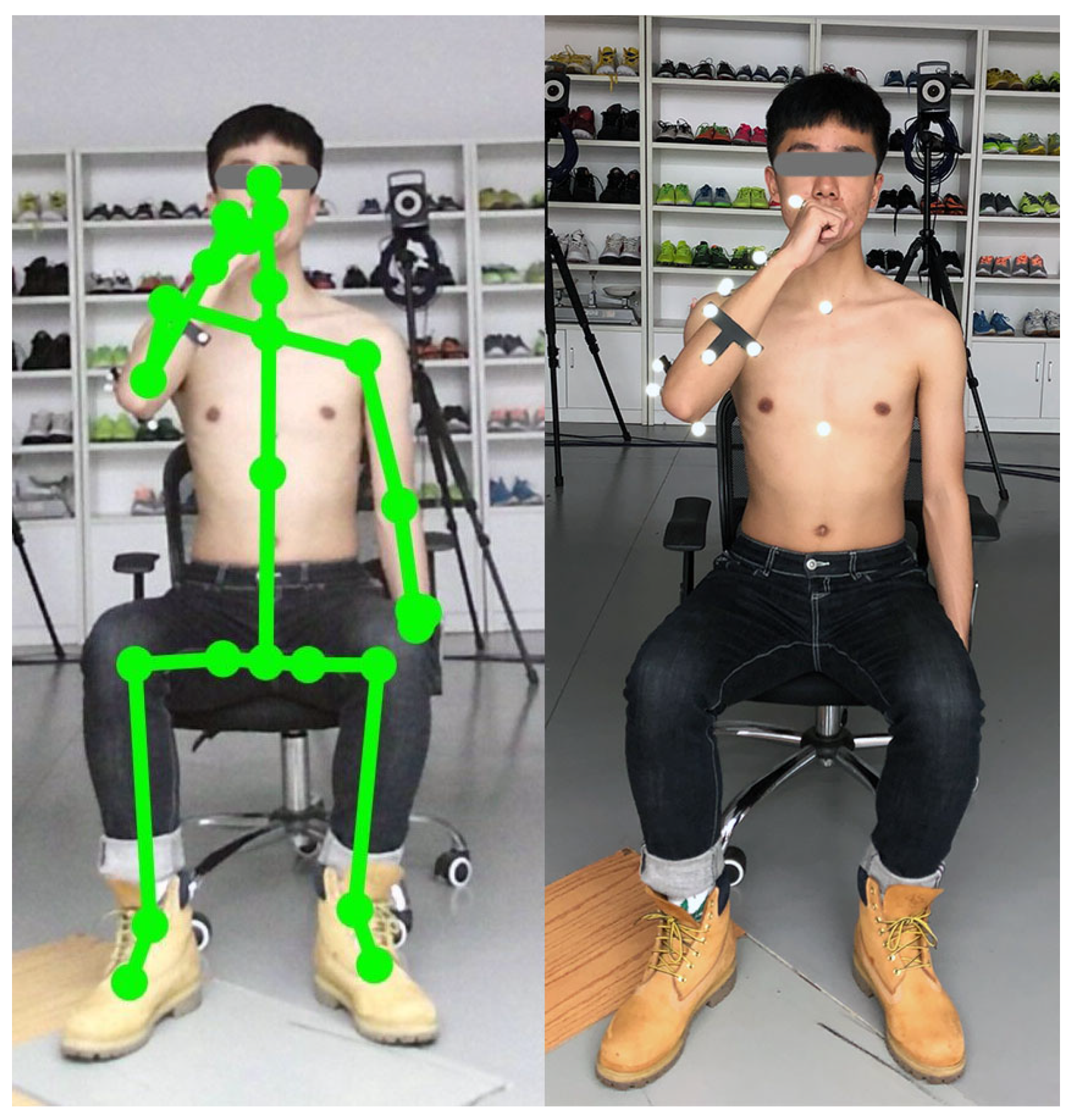
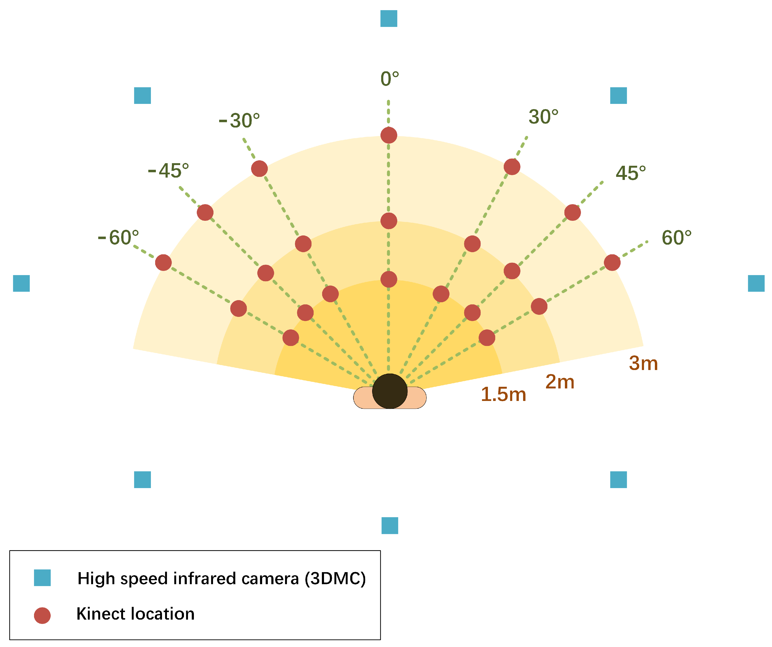
2.2. Experiment Procedures
2.3. Data Analysis
2.4. Statistical Analysis
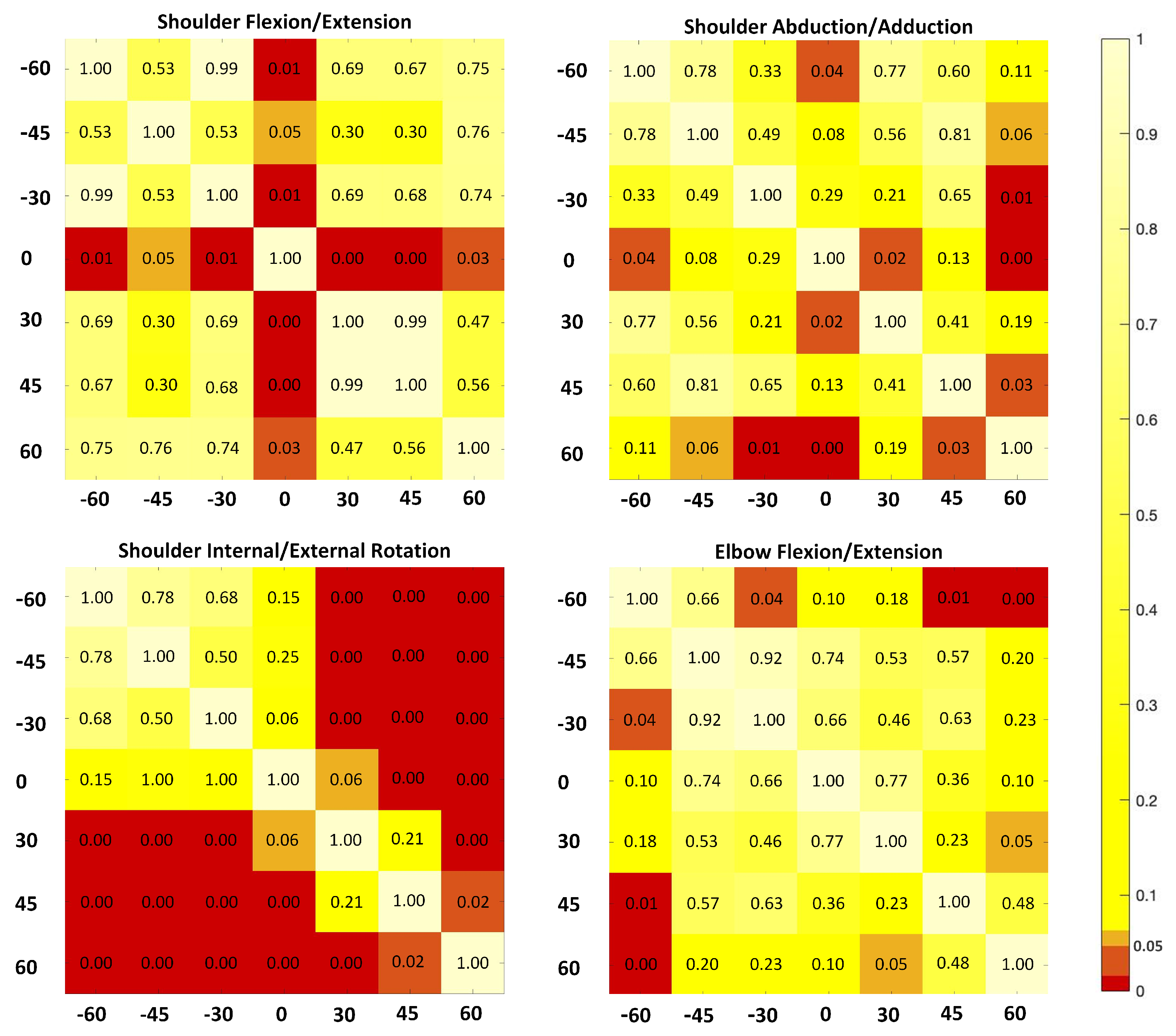
3. Results
4. Discussion
4.1. Effects of the Kinect Placement
4.2. Recommendations of the Kinect Placement for Dynamics Tasks
5. Conclusions
Author Contributions
Funding
Institutional Review Board Statement
Informed Consent Statement
Data Availability Statement
Acknowledgments
Conflicts of Interest
Abbreviations
| 3D | Three dimensional |
| 3DMC | Three-dimensional motion capture system |
| RGB-D | A depth sensor combined with an RGB-color camera |
| LSC | Local segment coordination |
| PTA | Angle at the point of target achieved |
| MEA | Mean absolute error |
| SL | Structured light |
| NIR | Near infra-red |
| TOF | Time of flight |
| CW | Continuous wave |
| FOV | Field of view |
References
- Winter, D.A. Biomechanics and Motor Control of Human Movement; John Wiley & Sons: Hoboken, NJ, USA, 2009. [Google Scholar]
- Walsh, J.C.; Quinlan, J.F.; Stapleton, R.; FitzPatrick, D.P.; McCormack, D. Three-dimensional motion analysis of the lumbar spine during “free squat” weight lift training. Am. J. Sport. Med. 2007, 35, 927–932. [Google Scholar] [CrossRef] [PubMed]
- Dutta, T. Evaluation of the KinectTM for 3-D kinematic measurement in the workplace. Appl. Ergon. 2012, 43, 645–649. [Google Scholar] [CrossRef]
- Ornetti, P.; Maillefert, J.F.; Laroche, D.; Morisset, C.; Dougados, M.; Gossec, L. Gait analysis as a quantifiable outcome measure in hip or knee osteoarthritis: A systematic review. Jt. Bone Spine 2010, 77, 421–425. [Google Scholar] [CrossRef]
- Clark, R.A.; Pua, Y.H.; Bryant, A.L.; Hunt, M.A. Validity of the Microsoft Kinect for providing lateral trunk lean feedback during gait retraining. Gait Posture 2013, 38, 1064–1066. [Google Scholar] [CrossRef]
- Frossard, L.; Cheze, L.; Dumas, R. Dynamic input to determine hip joint moments, power and work on the prosthetic limb of transfemoral amputees: Ground reaction vs knee reaction. Prosthet. Orthot. Int. 2011, 35, 140–149. [Google Scholar] [CrossRef] [Green Version]
- Pfister, A.; West, A.M.; Bronner, S.; Noah, J.A. Comparative abilities of Microsoft Kinect and Vicon 3D motion capture for gait analysis. J. Med. Eng. Technol. 2014, 38, 274–280. [Google Scholar] [CrossRef]
- Kinect. In Wikipedia; Wikimedia Fundation, 4 December 2020; Available online: https://en.wikipedia.org/wiki/Kinect (accessed on 5 March 2021).
- Shotton, J.; Fitzgibbon, A.; Cook, M.; Sharp, T.; Finocchio, M.; Moore, R.; Blake, A. Real-time human pose recognition in parts from single depth images. In Proceedings of the Proceeding CVPR, Colorado Springs, CO, USA, 20–25 June 2011; pp. 1297–1304. [Google Scholar]
- Clark, R.A.; Pua, Y.H.; Oliveira, C.C.; Bower, K.J.; Thilarajah, S.; McGaw, R.; Mentiplay, B.F. Reliability and concurrent validity of the Microsoft Xbox One Kinect for assessment of standing balance and postural control. Gait Posture 2015, 42, 210–213. [Google Scholar] [CrossRef] [PubMed]
- Latorre, J.; Llorens, R.; Colomer, C.; Alcañiz, M. Reliability and comparison of Kinect-based methods for estimating spatiotemporal gait parameters of healthy and post-stroke individuals. J. Biomech. 2018, 72, 268–273. [Google Scholar] [CrossRef]
- Ma, Y.; Liu, D.; Cai, L. Deep Learning-Based Upper Limb Functional Assessment Using a Single Kinect v2 Sensor. Sensors 2020, 20, 1903. [Google Scholar] [CrossRef] [Green Version]
- Paolini, G.; Peruzzi, A.; Mirelman, A.; Cereatti, A.; Gaukrodger, S.; Hausdorff, J.M.; Della Croce, U. Validation of a method for real time foot position and orientation tracking with Microsoft Kinect technology for use in virtual reality and treadmill based gait training programs. IEEE Trans. Neural Syst. Rehabil. Eng. 2013, 77, 997–1002. [Google Scholar] [CrossRef]
- Clark, R.A.; Pua, Y.H.; Fortin, K.; Ritchie, C.; Webster, K.E.; Denehy, L.; Bryant, A.L. Validity of the Microsoft Kinect for assessment of postural control. Gait Posture 2012, 368, 372–377. [Google Scholar] [CrossRef]
- Mentiplay, B.F.; Clark, R.A.; Mullins, A.; Bryant, A.L.; Bartold, S.; Paterson, K. Reliability and validity of the Microsoft Kinect for evaluating static foot posture. J. Foot Ankle Res. 2013, 6, 14. [Google Scholar] [CrossRef] [PubMed] [Green Version]
- Xu, X.; McGorry, R.W.; Chou, L.S.; Lin, J.H.; Chang, C.C. Accuracy of the Microsoft KinectTM for measuring gait parameters during treadmill walking. Appl. Ergon. 2017, 65, 418–423. [Google Scholar] [CrossRef] [PubMed]
- Mentiplay, B.F.; Perraton, L.G.; Bower, K.J.; Pua, Y.H.; McGaw, R.; Heywood, S.; Clark, R.A. Gait assessment using the Microsoft Xbox One Kinect: Concurrent validity and inter-day reliability of spatiotemporal and kinematic variables. J. Biomech. 2015, 48, 2166–2170. [Google Scholar] [CrossRef] [PubMed]
- Ma, Y.; Mithraratne, K.; Wilson, N.; Zhang, Y.; Wang, X. Kinect V2-Based Gait Analysis for Children with Cerebral Palsy: Validity and Reliability of Spatial Margin of Stability and Spatiotemporal Variables. Sensors 2021, 21, 2104. [Google Scholar] [CrossRef] [PubMed]
- Capecci, M.; Ceravolo, M.G.; Ferracuti, F.; Iarlori, S.; Longhi, S.; Romeo, L.; Verdini, F. Accuracy evaluation of the Kinect v2 sensor during dynamic movements in a rehabilitation scenario. In Proceedings of the IEEE Engineering in Medicine and Biology Society, Orlando, FL, USA, 16–20 August 2016; pp. 5409–5412. [Google Scholar]
- Mateo, F.; Soria-Olivas, E.; Carrasco, J.J.; Bonanad, S.; Querol, F.; Pérez-Alenda, S. HemoKinect: A microsoft Kinect v2 based exergaming software to supervise physical exercise of patients with hemophilia. Sensors 2018, 18, 2439. [Google Scholar] [CrossRef] [Green Version]
- Hu, G.; Wang, W.; Chen, B.; Zhi, H.; Li, Y.; Shen, Y.; Wang, K. Concurrent validity of evaluating knee kinematics using Kinect system during rehabilitation exercise. Med. Nov. Technol. Devices 2021, 11, 100068. [Google Scholar] [CrossRef]
- Uhlár, Á; Ambrus, M.; Kékesi, M.; Fodor, E.; Gr, L.; Szathmáry, G.; Lacza, Z. Kinect Azure–Based Accurate Measurement of Dynamic Valgus Position of the Knee—A Corrigible Predisposing Factor of Osteoarthritis. Appl. Sci. 2021, 11, 5536. [Google Scholar] [CrossRef]
- Mentiplay, B.F.; Hasanki, K.; Perraton, L.G.; Pua, Y.H.; Charlton, P.C.; Clark, R.A. Three-dimensional assessment of squats and drop jumps using the Microsoft Xbox One Kinect: Reliability and validity. J. Sport. Sci. 2018, 36, 2202–2209. [Google Scholar] [CrossRef]
- Chen, X.; Siebourg-Polster, J.; Wolf, D.; Czech, C.; Bonati, U.; Fischer, D.; Strahm, M. Feasibility of using Microsoft Kinect to assess upper limb movement in type III spinal muscular atrophy patients. PLoS ONE 2017, 12, e0170472. [Google Scholar] [CrossRef]
- Galna, B.; Barry, G.; Jackson, D.; Mhiripiri, D.; Olivier, P.; Rochester, L. Accuracy of the Microsoft Kinect sensor for measuring movement in people with Parkinson’s disease. Gait Posture 2013, 39, 1062–1068. [Google Scholar] [CrossRef] [Green Version]
- Ain, Q.U.; Khan, S.; Ilyas, S.; Yaseen, A.; Tariq, I.; Liu, T.; Wang, J. Additional Effects of Xbox Kinect Training on Upper Limb Function in Chronic Stroke Patients: A Randomized Control Trial. Healthcare 2021, 9, 242. [Google Scholar] [CrossRef]
- Mobini, A.; Behzadipour, S.; Saadat, M. Test–retest reliability of Kinect’s measurements for the evaluation of upper body recovery of stroke patients. Biomed. Eng. Online 2015, 14, 75. [Google Scholar] [CrossRef] [Green Version]
- Sarbolandi, H.; Lefloch, D.; Kolb, A. Kinect range sensing: Structured-light versus Time-of-Flight Kinect. Comput. Vis. Image Underst. 2015, 139, 1–20. [Google Scholar] [CrossRef] [Green Version]
- Yang, B.; Dong, H.; Abdulmotaleb, E.I. Development of a self-calibrated motion capture system by nonlinear trilateration of multiple Kinects v2. IEEE Sens. J. 2017, 8, 2481–2491. [Google Scholar] [CrossRef] [Green Version]
- Ryselis, K.; Petkus, T.; Blažauskas, T.; Maskeliūnas, R.; Damaševičius, R. Multiple Kinect based system to monitor and analyze key performance indicators of physical training. J. Hum.-Centric Comput. Inf. Sci. 2020, 10, 51. [Google Scholar] [CrossRef]
- Mortazavi, F.; Nadian-Ghomsheh, A. Stability of Kinect for range of motion analysis in static stretching exercises. PLoS ONE 2018, 7, e0200992. [Google Scholar] [CrossRef] [PubMed]
- Xu, X.; Robertson, M.; Chen, K.B.; Lin, J.H.; McGorry, R.W. Using the Microsoft Kinect™ to assess 3-D shoulder kinematics during computer use. Gait Posture 2017, 42, 145–151. [Google Scholar] [CrossRef] [PubMed] [Green Version]
- Seo, N.J.; Fathi, M.F.; Hur, P.; Crocher, V. Modifying Kinect placement to improve upper limb joint angle measurement accuracy. J. Hand Ther. 2016, 29, 465–473. [Google Scholar] [CrossRef]
- Rocha, A.P.; Choupina, H.M.P.; do Charmo Vilas-Boas, M.; Fernades, J.M.; Cunha, J.P.S. System for automatic gait analysis based on a single RGB-D camera. PLoS ONE 2018, 8, e0201728. [Google Scholar] [CrossRef] [Green Version]
- Yeung, L.F.; Yang, Z.; Cheng, K.C.C.; Du, D.; Tong, R.K.Y. Effects of camera viewing angles on tracking kinematic gait patterns using Azure Kinect, Kinect v2 and Orbbec Astra Pro v2. Gait Posture 2021, 87, 19–26. [Google Scholar] [CrossRef] [PubMed]
- Bourke-Taylor, H. Melbourne assessment of unilateral upper limb function: Construct validity and correlation with the pediatric evaluation of disability inventory. Dev. Med. Child Neurol. 2003, 45, 92–96. [Google Scholar] [CrossRef] [PubMed]
- Duncan, P.W.; Propst, M.; Nelson, S.G. Reliability of the Fugl-Meyer assessment of sensorimotor recovery following cerebrovascular accident. Phys. Ther. 1983, 63, 1606–1610. [Google Scholar] [CrossRef] [PubMed]
- Wolf, S.L.; Catlin, P.A.; Ellis, M.; Archer, A.L.; Morgan, B.; Piacentino, A. Assessing Wolf motor function test as outcome measure for research in patients after stroke. Stroke 2001, 32, 1635–1639. [Google Scholar] [CrossRef] [PubMed] [Green Version]
- Zhang, Y.; Unka, J.; Liu, G. Contributions of joint rotations to ball release speed during cricket bowling: A three-dimensional kinematic analysis. J. Sport. Sci. 2011, 29, 1293–1300. [Google Scholar] [CrossRef]
- Bartlett, R. Introduction to Sports Biomechanics: Analysing Human Movement Patterns; Routledge: Abingdon, UK, 2014. [Google Scholar]
- Cohen, J. Statistical Power Analysis for the Behavioral Sciences. Curr. Dir. Psychol. Sci. 2013, 1, 98–101. [Google Scholar] [CrossRef]
- van Andel, C.J.; Wolterbeek, N.; Doorenbosch, C.A.; Veeger, D.H.; Harlaar, J. Complete 3D kinematics of upper extremity functional tasks. Gait Posture 2008, 27, 120–127. [Google Scholar] [CrossRef]
- Albert, J.A.; Owolabi, V.; Gebel, A.; Brahms, C.M.; Granacher, U.; Arnrich, B. Evaluation of the pose tracking performance of the azure kinect and Kinect v2 for gait analysis in comparison with a gold standard: A pilot study. Sensors 2020, 20, 5104. [Google Scholar] [CrossRef]
- Wang, Q.; Kurillo, G.; Ofli, F.; Bajcsy, R. Evaluation of pose tracking accuracy in the first and second generations of microsoft kinect. In Proceedings of the International Conference on Healthcare Informatics, Dallas, TX, USA, 21–23 October 2015; pp. 380–389. [Google Scholar]
- Grzegorzek, M.; Theobalt, C.; Koch, R.; Kolb, A. Time-of-Flight and Depth Imaging. In Sensors, Algorithms and Applications: Dagstuhl Seminar 2012 and GCPR Workshop on Imaging New Modalities; Springer: Berlin/Heidelberg, Germany, 2013; Volume 8200. [Google Scholar]

| Name | Definition | |
|---|---|---|
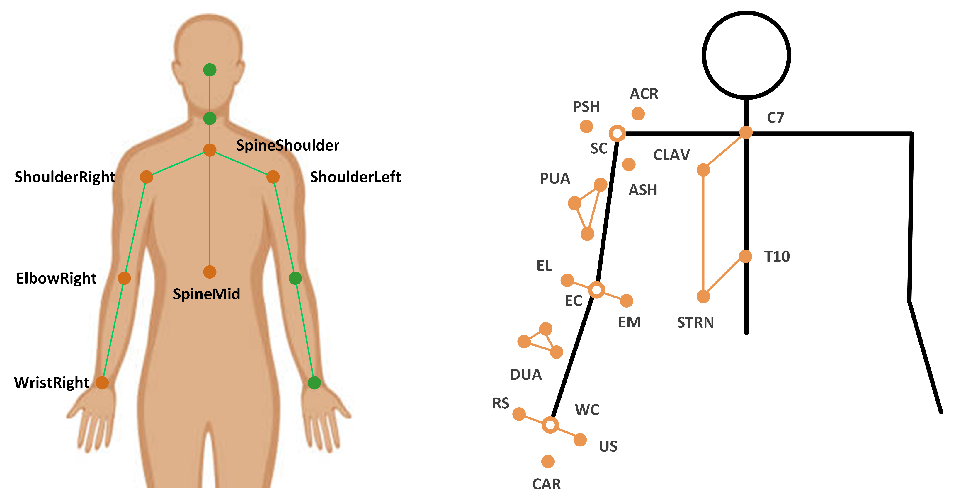
| Torso | Origin | SpineShoulder |
| X | Unit vector perpendicular to two vectors (Y and the vector from ShoulderRight to ShoulderLeft) | |
| Y | Unit vector going from SpineMiddle to SpineShoulder | |
| Z | Unit vector defined by the X-axis and the Y-axis to create a right-hand coordinate system | |
| Upper Arm | Origin | The elbow joint center (ElbowRight) |
| X | Unit vector perpendicular to the Y-axis and the Z-axis, pointing anteriorly | |
| Y | Unit vector going from SpineMiddle to SpineShoulder | |
| Z | Unit vector defined by the X-axis and the Y-axis to create a right-hand coordinate system |
| Joint Angle | Distance | Mean (SD) | Orientation | Mean (SD) | p Value of ANOVA | ||
|---|---|---|---|---|---|---|---|
| Main Effect | p Value | eta | |||||
| Shoulder Flex/Ext | 1.5 | 27.96 (5.02) | 26.17 (5.93) | Distance | 0.94 | 0.10 | |
| 29.63 (11.06) | |||||||
| 2 | 27.12 (4.41) | 24.79 (10.87) | Orientation | 0.05 | 0.21 | ||
| 0 | 36.66 (10.61) | ||||||
| 3 | 25.04 (6.55) | 30 | 23.71 (8.82) | Distance * Orientation | 0.78 | 0.12 | |
| 45 | 23.02 (9.98) | ||||||
| 60 | 23.34 (7.56) | ||||||
| Shoulder Abd/Add | 1.5 | 6.11 (2.43) | −60 | 4.80 (3.05) | Distance | 0.85 | 0.09 |
| −45 | 6.56 (5.29) | ||||||
| 2 | 6.26 (3.14) | −30 | 6.74 (4.19) | Orientation | 0.02 | 0.24 | |
| 0 | 2.85 (1.71) | ||||||
| 3 | 6.41 (1.95) | 30 | 7.33 (7.46) | Distance * Orientation | 0.92 | 0.14 | |
| 45 | 6.05 (3.56) | ||||||
| 60 | 9.38 (8.49) | ||||||
| Shoulder IR/ER | 1.5 | 18.93 (10.56) | −60 | 8.29 (7.29) | Distance | 0.99 | 0.06 |
| 11.26 (11.18) | |||||||
| 2 | 19.70 (11.32) | −30 | 9.42 (8.15) | Orientation | 0.02 | 0.22 | |
| 0 | 16.91 (9.26) | ||||||
| 3 | 19.27 (11.92) | 30 | 23.73 (10.8) | Distance * Orientation | 0.85 | 0.15 | |
| 45 | 28.86 (10.84) | ||||||
| 60 | 36.83 (15.17) | ||||||
| Elbow Flex/Ext | 1.5 | 22.49 (7.65) | −60 | 21.46 (8.73) | Distance | 0.55 | 0.08 |
| 22.61 (11.14) | |||||||
| 2 | 21.61 (9.20) | −30 | 10.20 (5.75) | Orientation | 0.05 | 0.54 | |
| 0 | 21.37 (6.46) | ||||||
| 3 | 19.27 (11.92) | 30 | 18.91 (7.66) | Distance * Orientation | 0.34 | 0.18 | |
| 45 | 25.54 (7.43) | ||||||
| 60 | 28.32 (4.83) | ||||||
Publisher’s Note: MDPI stays neutral with regard to jurisdictional claims in published maps and institutional affiliations. |
© 2021 by the authors. Licensee MDPI, Basel, Switzerland. This article is an open access article distributed under the terms and conditions of the Creative Commons Attribution (CC BY) license (https://creativecommons.org/licenses/by/4.0/).
Share and Cite
Cai, L.; Liu, D.; Ma, Y. Placement Recommendations for Single Kinect-Based Motion Capture System in Unilateral Dynamic Motion Analysis. Healthcare 2021, 9, 1076. https://doi.org/10.3390/healthcare9081076
Cai L, Liu D, Ma Y. Placement Recommendations for Single Kinect-Based Motion Capture System in Unilateral Dynamic Motion Analysis. Healthcare. 2021; 9(8):1076. https://doi.org/10.3390/healthcare9081076
Chicago/Turabian StyleCai, Laisi, Dongwei Liu, and Ye Ma. 2021. "Placement Recommendations for Single Kinect-Based Motion Capture System in Unilateral Dynamic Motion Analysis" Healthcare 9, no. 8: 1076. https://doi.org/10.3390/healthcare9081076
APA StyleCai, L., Liu, D., & Ma, Y. (2021). Placement Recommendations for Single Kinect-Based Motion Capture System in Unilateral Dynamic Motion Analysis. Healthcare, 9(8), 1076. https://doi.org/10.3390/healthcare9081076