1. Introduction
Symmetries are common in civil engineering, in all types of buildings and constructions. They are also common in structures with large roofs such as industrial warehouses, different exhibition halls, sports complexes, covered stadiums, and a large range of public places and other modern facilities. Using symmetries involves many advantages for the builder. First, the design time is reduced, then the calculation of these mechanical systems is also reduced considering the substructures that can be treated separately [
1]. Furthermore, the manufacture of these buildings becomes easier as the number of different elements decreases. Advantages are also offered in the case of vibration calculation where it is found that the number of operations that can be performed for such an analysis can be significantly reduced [
2,
3]. All these elements can lead to lower costs related to structures that have symmetries. The existence of symmetries and their use has long been observed and are used by designers and users of the finite element method in practical applications [
4]. The main idea that helps the builder and designer is that the information needed to describe such a system is reduced, which allows a reduction of the operations required for design and calculation and to facilitate both static and dynamic analysis. Particular cases of systems with different symmetries have been studied by different authors and presented in the papers [
5,
6,
7,
8,
9,
10].
In general, research has focused more on how these symmetries influence the formal aspects and how to write equations of motion [
11,
12,
13]. Practical, engineering applications have been less addressed in the literature, although designers and users of computer programs know some properties and use them. Symmetries can occur not only in civil engineering but also in manufacturing industry, as well as in automotive and aerospace engineering where parts of a product or of a machine are repetitive or identical.
We note that the existence of repetitive elements has long been observed in the aviation industry and has become a relatively common method to reduce computational time. Parts of the main structure are condensed into substructures. Any of these substructures contain a lower number of degrees of freedom than the original structure. If such a substructure has been generated, building the model for the entire structure becomes easier [
14].
Modeling such a system ultimately leads to a system of differential equations that offers the dynamic response. Considering the symmetries, it makes it easier to write these equations and can lead to simpler methods of solving them [
15,
16].
Modern building solutions for industrial warehouses, exhibition halls, sports complexes, public meeting places, or other modern facilities require large roofs and the solution commonly used at this time is that of layered spatial grids (double or triple layer configurations). These constructions have, in the current solutions, a high degree of symmetry, at a modular and global level. The symmetries allow the easing of the calculation in case of dynamic analysis and system vibrations. In the paper [
17] the symmetries of the configurations of the stratified spatial grids are analyzed and a theoretical group approach is used to determine the associated vibrations.
Group theory has long been used to study phenomena in different fields of physics and chemistry, such as quantum mechanics, crystallography, and molecular structure. However, in engineering mechanics as well, the use of symmetries allows the simplification of the analysis of such systems and can become important in the study of vibrations or kinematic analysis. Mathematically, the symmetry properties of a system are described by symmetry groups. Furthermore, if a system has several types of symmetries, the question may arise which of all these types is the most suitable for a study. An analysis made to identify which of the symmetry groups has the most favorable computational implications and presents a rational criterion for determining the most efficient symmetry group of the calculation is presented in [
18].
In the field of engineering, the identification of systematic and efficient strategies for using the properties involved by different types of symmetries in determining the static or dynamic response of mechanical structures has allowed a development of theoretical group methods, which has happened especially in the last four decades. Works in the field have highlighted the main aspects that appeared in such studies [
19,
20]. Some similar results can be found in [
21,
22,
23]. The theoretical approach of the properties of the symmetry group allows obtaining valuable and useful information from a practical point of view about the mechanical response or the properties of such a system, before performing any real calculations.
The different symmetries were applied more to shows some properties of the mathematical formulations and less to applied in the case of engineering applications. An example is represented by the use of the Lie symmetries and similarity to reduction of a class of wave equations [
24]. In this case the major advantage is the possibility to solve a number of complicated and difficult to solve equations.
Many studies have dealt with the aesthetic impact of symmetries, which is not of interest to engineers. The paper [
25,
26] illustrates very well this field of research. In architecture, symmetry is a criterion in aesthetic judgment, but can determine a development and simplification of computational procedures. Therefore, there are developed mathematical symmetry measurement models that can help the architectural design.
The cases of systems with different types of symmetries are numerous and research in the field is welcome for the accumulation of results that provide useful tools to the engineer. In the case of the work, it is considered a situation that can often be encountered in the construction of buildings, namely, that of a concrete pillar, embedded at the base and connected by four identical bars to the rest of the construction.
2. Modeling the Structure
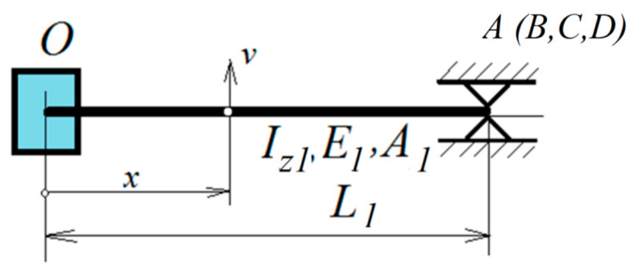
Consider a vertical reinforced concrete truss that supports four identical bars, all of them made of the same material (it can be metal). The concrete truss is clamped at the lower end and can have torsional vibrations and the four bars at the top can bend in the horizontal plane. It is considered that the rigidity of the four bars in the vertical plane is high enough so that the vibrations in this plane can be neglected. The vertical EO truss is the main element of the system and has the length L1. The secondary beams OA, OB, OC, and OD are rigid fixed in the point O. The other ends are simply supported (in A, B, C, D) and are made monolithically. O is a rigid knot. The secondary bars are arranged symmetrically around the point O. They have the Young’s moduli E2, the length L2, the moment of inertia Iz2, and the area of section A2. The truss EO has the Young’s moduli E1, the section area A1, and the moment of inertia Iz1. The properties presented below give the reduction of the calculation effort necessary for the analysis of the vibrational response of such structures. A simple structure is analyzed in order to be able to describe these properties more suggestively. Applying these methods to more complex structures should lead to significant time savings in performing a calculation in the case of design processes. Since computational effort usually increases more strongly than linearly when solving such problems, it is assumed that these operations lead to a substantially lower effort for the analysis of complex systems.
The model (
Figure 1) consists of four homogenous beam, rigidly fixed in O, perpendicular to a fifth beam EO. The last element EO, clamped in E, can have torsional vibration around his axis, and the four identical beam can bend in a horizontal plane and are rigidly fixed in O. The torsion angle of the truss EO in O becomes equal with the slopes of the beam OA, OB, OC, and OD in O.
It is considered now a homogeneous concrete truss with a constant section to study the response of a single element. We have the problem of studying the transverse vibrations of these beams in a plane. The problem is well-known and presented in the literature [
27]. The motion equations of the beam vibration are offered by the fourth order differential equation:
In this equation (Equation (1)) the notations used are the following: v is the deflection of a point of beam, A represents the cross section area, is the mass density, E represents the longitudinal modulus of elasticity (Young’s modulus), Iz is the second area moment of inertia, and x is the ordinate of the current point considered.
To usual way to solve Equation (1) is to consider a solution of the form:
Therefore, the function
depending on
x and
t is written as the product of two functions, one depending on
x and other depending on
t. Introducing Equation (2) in Equation (1) the following is obtained:
In Equation (5), represents the deformed beam (eigenmode) corresponding to its eigenvalue. In the following, we will use Equation (5) for the all four trusses, obtaining in this way four differential equations of the fourth order, corresponding to the frames OA, OB, OC, OD.
Considering the beam OA, we have
we can also write for the beam OB:
for the beam OC:
for the beam OD:
The following notations are made:
and the Equations (6)–(9) become
Using (10), the four solutions for the four differential equations of order four (11) are
The beam EO has only torsional vibrations. This vibration is described by the second order differential equation:
where
is the angle of torsion,
is the polar moment of inertia,
is the polar second moment of the area, and
G is shear’s modulus.
For the Equation (16) it considers a solution of the form:
from where it results:
where the following notation was made:
The solutions of the Equations (18) is:
The free vibrations of this system are described by Equations (11) and (16) with solutions (12)–(15) and (20). The solutions contain 18 integration constants depending on the boundary conditions.
Denote by the bending moment of a beam in section x, T the shear force appearing in the cross section of the beams OA, OB, OC, OD, and with the torque in the beam EO. The boundary conditions for our application are
- (a)
For the OA, OB, OC, OD trusses the end O is clamped, thus: ; ;
- (b)
For the OE beam the end E is clamped, thus:
- (c)
For the OA, OB, OC, OD trusses the ends A, B, C, D are supported, thus: ; ; ; ; .
Therefore, we have 17 boundary conditions. Below we will express these conditions in an analytical form. The bending moments and the torsion torque are expressed by the known relationships in the mechanics of the deformable solid [
28,
29]:
If the conditions (a), (b), and (c) are taken into account, the following relations will be obtained:
which represents a system of 17 equations with 18 unknowns.
One more condition is needed in order to obtain the integration constants. The equilibrium relation is obtained for bending and torsional moments:
If Equation (21) is taken into account, it obtains
or
where the notation
has been made.
From the system formed by Equations (31)–(47), (50) we must determine the constants
,
,
,
,
,
,
,
,
,
,
,
,
,
,
,
,
,
,
,
. We denote:
with:
Therefore, it was obtained a homogeneous linear system with 18 equations with 18 unknown (31)–(47) and (50). To have other solutions besides the trivial solution zero, the determinant of the system must be zero. Note:
If we denote
the system can be written:
The conditions:
offers the eigenvalues of the system.
3. Properties of Eigenvalues
Let us now consider one of the identical truss OA (OB, OC, OD) (see
Figure 2). The truss is clamped in O and supported it in B (or C). Equation (1) is also valid for the OB bar (OC) written in the form,
with the boundary conditions:
Considering the point O, the boundary conditions are
and the boundary conditions for the other end are
The classic solution:
introduced in Equation (64) offers
where:
The solution of the Equation (68) is [
27]:
Considering the boundary conditions it results in:
It is now possible to determine the constants
from the linear homogenous system:
where
is the matrix determined by Equation (57).
If the condition of the existence of non-zero solutions is set:
the eigenvalues of the truss OA (/OB/OC/OD) for the transverse vibrations can be computed.
The following theorems has been proved in a previous paper [
30]:
Theorem 1. The eigenvalue for the trusses OA/OB/OC/OD, supported at the both ends, are also eigenvalues for the whole system.
From this it results that the eigenvalues of a single truss, supported at both ends, are between eigenvalues of the entire system.
4. Eigenmodes of Deformation
If the matrix (61) is given and the eigenvalues have been calculated, for these values the eigenmodes of deformation of the bar are obtained from Equation (62) written in the form:
We denote by {B} the vector of the constants calculated for the eigenvalues obtained from the condition (76). The following two theorems will be proved:
Theorem 2. For the other eigenvalues to which Theorem 1 does not refer, the eigenvectors are of the formwith.
Proof. For the eigenvalues obtained from (76) the following system must be solved:
where
satisfies the condition (76).
Condition (77) implies that a vector
can be found such that
From (81)–(85) taking into account the Equation (80), it results:
From (86), because in general det (
A12) ≠ 0, it follows immediately:
and introducing in (87), it results
.
Theorem 3. For the other eigenvalues, the eigenvectors are of the form:where:.
Proof: For the determined eigenvalues the system (62) must be solved, with . Equation (62) becomes, after performing some simple calculations:
Subtracting (91) from (90), (92) from (90), and (93) from (90) we obtain:
from where:
Equation (94) becomes:
and
can be expressed as
□
5. Conclusions
Symmetries are a common thing in the construction of buildings, roofs with large openings, industrial halls, gyms, performance halls, and other public places. The existence of these symmetries leads to advantages in the sense that the information regarding the respective structure is reduced and, as a result, a series of operations related to the design or execution can also be reduced. Repetitive elements or symmetries can be found practically everywhere. The design of such a structure is simpler, the calculations needed to be done are less, and as a result, the construction costs become lower. If we refer only to the calculation of the vibrations of the structure, which is the subject of the paper, the existence of symmetries can bring significant advantages. It can reduce the number of operations that can be performed and the result is time-saving in regards to design and cost reducing.
In this the paper, several properties related to the eigenvalues and eigenmodes of vibration of such a structure were presented. Knowledge of these properties becomes useful to the engineer and the paper completes the cases of systems with symmetries already studied.


