Abstract
A novel geometric modeling and calculation method for forward displacement analysis of the 6-3 Stewart platforms is proposed by using the conformal geometric algebra (CGA) framework. Firstly, two formulas between 2-blade and 1-blade are formulated. Secondly, the expressions for two spherical joints of the moving platform are given via CGA operation. Thirdly, a coordinate-invariant geometric constraint equation is deduced. Fourthly, a 16-degree univariate polynomial equation without algebraic elimination by using the Euler angle substitution is presented. Fifthly, the coordinates of three spherical joints on the moving platform are calculated without judging the radical symbols. Finally, two numerical examples are used to verify the method. The highlight of this paper is that a new geometric modeling and calculation method without algebraic elimination is obtained by using the determinant form of the CGA inner product algorithm, which provides a new idea to solve a more complex spatial parallel mechanism in the future.
1. Introduction
The parallel mechanism (PM) [1,2,3,4] is composed of a moving platform and a fixed platform, which is connected by at least two independent kinematic chains and has two or more degrees of freedom (DOF). Compared with the traditional series mechanism, the spatial parallel mechanism has the advantages of higher rigidity, precision, and strong bearing capacity, etc. At present, the most widely studied parallel mechanism is the 6-DOF parallel mecha-nisms first proposed by Gough [1] and widely used by Stewart [2]. The classification of all self-motions of the origi-nal Stewart–Gough platform was achieved by Luces and Benhabib [3]. The redundant parallel kinematic mecha-nisms are introduced by Karger and Husty [4]. Traditionally, Eduard Study [5] put forward a novel method to de-fine a rigid body displacement in 3-dimension space, and mapped each position of a rigid body onto a point on a quadric, now called the Study quadric. In this paper, the motion of the rigid body (here, the moving platform) is described by the position coordinates of three spherical joints on the moving platform. The forward displacement analysis of the parallel mechanism is to calculate the position and attitude of the moving platform relative to the static platform via the driving rod length of the parallel mechanism. This problem is the theoretical basis of the ve-locity, acceleration, error analysis, workspace analysis, singular position analysis, dynamic analysis, and other problems of the mechanism. For the elimination of equations, the Newton–Raphson method [6] and polynomial constraints solver [7] are commonly used.
In this discourse, we will revisit the forward displacement analysis of the 6-3 Stewart platforms (6-3SPS mechanisms), which has been researched in [8,9,10,11,12,13,14]. Griffis et al. [8] managed to present a closed-form solution to the platform mechanisms of the 6-3SPS. Nanua et al. [9] published the 16th-order input-output equation. Innocenti et al. [10] revealed the solution of a system of three second-order nonlinear equations. Merlet et al. [11] put forward a method for the forward displacement analysis of 6-3 Stewart platforms by finding a polynomial in one variable whose roots determine the posture of the mobile plate. Zhang et al. [12] and Wei et al. [13] committed to an inves-tigation into forward displacement analysis of the 6-3 Stewart platforms using the resultant method and the CGA theory. Zhang et al. [14] settled the forward displacement analysis for the 6-3 Stewart platforms only using the CGA method.
Conformal geometric algebra (CGA) [14,15,16,17,18,19,20,21,22,23,24,25,26,27] is a new geometric representation and calculation framework, which can uniformly represent point, line, plane, circle, and other geometric elements. CGA is committed to present direct algebraic operations on these geometric entities. These operations usually produce formulas that are inde-pendent of the coordinate system and make complex symbolic geometry computation possible. The above features are two important intrinsic attributes of CGA. Therefore, it is useful and suitable for the geometric modeling and calculation of mechanism kinematics. In recent decades, CGA had been used to deal with the inverse kinematics problem of the serial mechanism through CGA operation of geometric entities [19,20,21]. Additionally, Song et al. [22] employed the CGA theory in topology synthesis of mechanisms. Furthermore, Hrdina et al. [23,24,25] committed to an investigation into robotic modeling and control by CGA theory. Zhang et al. [14,26] and Huang et al. [27] per-formed exploration on addressing the forward displacement analysis of the serial mechanism in virtue of CGA the-ory.
In this paper, a new geometric modeling and calculation method for closed-form solution of the 6-3 Stewart platforms is proposed by using the CGA framework which contributes to a 16-degree univariate input-output pol-ynomial equation without algebraic elimination and superfluous roots. Although the forward displacement prob-lems of the 6-3 Stewart platforms have been addressed by Zhang et al. [12,14] and Wei et al. [13] using CGA, the proposed method based on the determinant operation formula (Equation (8)) of the CGA inner product provides a new idea to solve more a complex spatial parallel mechanism in the future, which is not available in Refs. [12,13,14]. In addition, compared with [14] in the back substitution procedure, the proposed method does not need to determine the radical symbols. Moreover, two formulas between 2-blade and 1-blade are first formulated.
The remaining of the paper is formulated as follows. In Section 2, the foundations of CGA will be presented. In Section 3, the derivation of two formulas between 2-blade and 1-blade under the CGA framework is elaborated. In Section 4, the geometric modeling and calculation process of the 6-3 Stewart platforms will be revealed. In Section 5, two numerical examples of 6-3 Stewart platforms will be given. Finally, the conclusions will be built in Section 6.
2. Conformal Geometric Algebra
2.1. Foundations of CGA
The 5-dimension (5D) CGA consists of 3D Euclidean space and a 2D Minkowski vector space . CGA has five orthonormal basis vectors introduced by with the following properties:
where are three orthonormal basis vectors in the Euclidean space and are two orthogonal basis vectors in the Minkowski space.
In addition, two null bases can be presented by the vectors:
with the properties of:
where is the conformal origin and is the conformal infinity.
Blade is the basic calculation element and basic geometric entity of geometric algebra. The 5D CGA consists of 0, 1, 2, 3, 4, and 5 blades. The blade with the largest grade, namely 5-blades, are called pseudo-scalars and defined by . A linear combination of blades with different grades is called a multi-vector.
The dual of a multi-vector is denoted by:
where is the inverse of .
Conformal geometric algebra has three algebraic operators: the inner product (), the outer product (), and the geometric product (). Inner product is used to solve geometric scalars. The outer product is applied to build basic geometry or the geometry intersection. The inner and outer products of two vectors and can also be built as:
and:
The inner product of between an r-blade and an s-blade can be defined by:
with:
As a supplement, if is equal to , the inner product of between an r-blade and an s-blade can also be obtained by:
For two blades and with non-zero grades and , the inner and outer products can be denoted as:
2.2. Conformal Geometric Entities
CGA has a visual representation of basic geometric entities. The representations of geometric entities relative to inner product null space (IPNS) and outer product null space (OPNS) are listed in Table 1. IPNS refers to the geometric entity achieved by the intersection of geometric entities, and OPNS refers to the geometric entity described by the points belonging to the geometric entity. The two representations can be transformed by dual operators. Detailed information is given by references [15,16,17,18]. In Table 1, small italics and bold characters represent points or vectors in Euclidean space. The character is the radius of sphere . The character is a normal vector of plane . The symbol represents the distance from the origin of the coordinate system to the plane .

Table 1.
The geometric element of CGA.
The inner product between two points and is summarized as:
3. Two Formulas under the Framework of CGA
In this section, the derivation of two formulas between 2-blade and 1-blade under the CGA framework is elaborated. In order to facilitate the derivation of the formula, the following formula is first given using Equation (7) under the framework of CGA, i.e.,:
where and are both 2-blades, , and . , , , , , and are all 1-blades. The detailed derived procedure of Equation (12) is given in the Appendix A.
3.1. Derivation of the First Formula
According to Equation (12), we can obtain:
By multiplying both sides of Equation (17) with and simplifying it, we obtain:
Using Equations (13)–(16), we obtain:
3.2. Derivation of the Second Formula
According to Equation (14), we can obtain:
According to Equation (12), Equation (20) is simplified as:
Expanding the right side of Equation (21) using Equation (11), we can obtain:
Using Equation (15), Equation (22) is simplified as:
Equations (19) and (23) are derived from Equation (12) and are frequently used in this paper.
4. CGA-Based Geometric Modeling and Calculation Procedure
In this section, the structure and coordinate system of the 6-3 Stewart platform is first presented. Then, the expressions for two point pairs and are given. Next, a coordinate-invariant geometric constraint equation is deduced. Finally, the coordinates of three spherical joints on the moving platform will be calculated. In this paper, three spherical joints on the moving platform are equivalent to three points.
4.1. The Structure and Coordinate System of the 6-3 Stewart Platforms
The 6-3 Stewart platforms structure is shown in Figure 1. The 6-3 Stewart platforms are connected by a moving platform , a static platform and six SPS kinematic chains. The SPS kinematic chain is composed of revolute joint , prismatic joint , and spherical joint , where prismatic joint is the actuated joint. The coordinate system is the geodetic coordinate system. The coordinate systems are attached to the static platform . The origin of the coordinate system is considered to coincide with the origin of the coordinate system . The geometric center coordinates of the spherical joints on the static platform and the spherical joints on moving platform are represented by and . The distance between the three spherical joints on the moving platform is denoted by . are the input of the six SPS kinematic chains and are unknown.
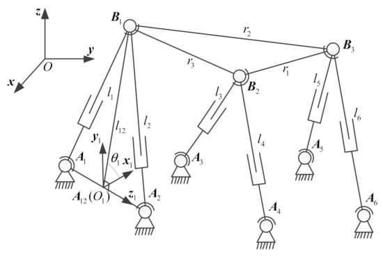
Figure 1.
The structure of 6-3 Stewart platforms.
The coordinate system is rotated by about the Z1-axis, and the new X1-axis is rotated by . The unit vector of the Z1-axis is defined as . As a consequence, the coordinate system coincides with the coordinate system , and the expressions of and are denoted as:
In addition, the matrix is represented as:
where ,,, and .
4.2. The Expressions for Two Point Pairs and .
According to Figure 1, point is situated on sphere , whose center is point and radius is , and sphere , whose center is point and radius is . In addition, point is also located on sphere whose center is point and radius is . Considering Table 1, the point pair can be denoted as:
where , and can be formulated as:
Using Equation (4), the dual of point pair can be represented as:
Homogeneously, point is located on sphere whose center is point and radius is , sphere whose center is point and radius is , and sphere whose center is point and radius is . Hence, the point pair can be formulated as:
where , and can be expressed as:
4.3. The Coordinate-Invariant Geometric Constraint Equation
According to Table 1 and Equation (10), we can obtain:
According to the formula to dissect a point from the point pair [14,27], we have:
where , and , and are both 4-blade.
According to Table 1, sphere is represented as
where .
By substituting Equation (30) into Equation (31), we obtain:
By substituting Equation (32) into Equation (29) and simplifying it, we have:
where:
, is 4-blade.
According to Equation (33), we derive:
and expanding Equation (34), we have:
where:
, . are all scalars. and are both 4-blade.
By multiplying both sides of Equation (35) with and simplifying it, we have:
where .
Simplifying the coefficients ,,,, and by using Equations (1)–(10), we have:
where ,, and are both 4-blade:
,,, and are all scalars. In addition, the detailed simplification procedure of is given in the Appendix B.
For the 6-3 Stewart platforms, the geometric constraint equation Equation (36) depends on only the design parameters, the inputs, and the coordinates of point .
4.4. The Univariate Polynomial Equation for Forward Displacement Analysis
According to Table 1, point can be denoted in CGA as:
where the coordinates of point in coordinate system O-XYZ can be expressed as:
According to Equations (36) and (42), a 16th-degree polynomial equation about is formulated by using the Euler angle substitution (, , and ).
4.5. Back Substitution
After the values of are given, the coordinates of point can be solved by Equation (42). Two point pairs and can be calculated using Equations (27) and (28). According to Table 1, we can obtain:
where the coordinates of point are unknown.
Since two values for point can be solved by Equation (30), aiming to receive the unique value of point , a novel objective function for point is formulated as:
where , , , , .
By expanding Equation (45), we readily obtain:
where , ,
. , , and are all 1-blade.
By simplifying the 1-blades , and , we obtain:
The expression of point is the expression for a point ( or ) of point pair . Analyzing carefully Equation (45), on the one hand, when is equal to zero, we can have . On the other hand, when is equal to zero, we can also acquire . and are both 4-blade. Therefore, we can obtain the coordinates of point by the normalization of a point in CGA, i.e.,:
By substituting Equation (47) into Equation (44), the coordinates of point are equal to the normalization of 4-blade , i.e.,:
4.6. Two Comparisons
Compared with the traditional algebra method for forward displacement analysis of 6-3 Stewart platforms, the method proposed in this paper has the following characteristics:
(1) The derivation process of the proposed method is geometrically intuitive due to the intuitiveness of CGA.
(2) The univariate symbolic polynomial equation (Equation (36)) is derived directly by CGA operation without algebraic elimination.
Compared with the existing geometric algebra method to solve 6-3 Stewart platforms, the characteristics of this method proposed in this paper are as follows:
(1) In the back substitution procedure, the proposed method does not need to determine the radical symbols.
(2) Two formulas between 2-blade and 1-blade are first formulated.
(3) The proposed method based on the determinant operation formula (Equation (8)) of the CGA inner product provides a new idea to solve a more complex spatial parallel mechanism in the future, which is not available in Refs. [12,13,14].
5. Numerical Example
In order to verify the proposed modeling and calculation method using the CGA framework, two numerical examples of the 6-3 Stewart platforms are given.
5.1. Example 1
The structural parameters and inputs of the 6-3 Stewart platforms are as follows:
Substituting the link parameters and inputs into Equation (36), the polynomial of degree sixteen is formulated as:
The sixteen sets of solutions received by solving the polynomial equation Equation (49) agree with those given in [13,14]. The four sets of real solutions are shown in Table 2 and Figure 2.

Table 2.
Four sets of real solutions of point .
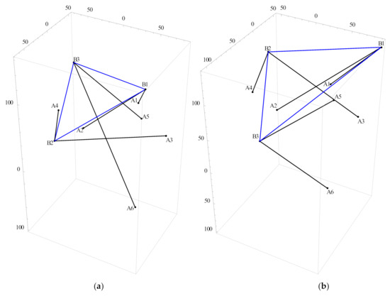
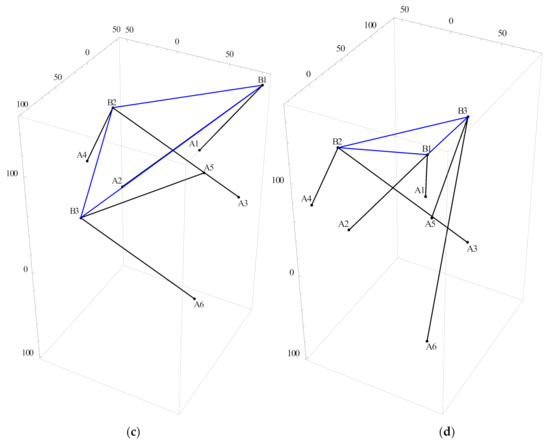
Figure 2.
Four assembly configurations (a, b, c, d) of 6-3 Stewart platforms.
5.2. Example 2
The link parameters and inputs of the planar 6-3 Stewart platforms are shown in Table 3. According to the steps mentioned above, substituting the link parameters and inputs into Equation (36), we can obtain sixteen solutions. The sixteen sets of solutions are consistent with those given in [14]. The four sets of real solutions are shown in Table 4 and Figure 3.

Table 3.
Link parameters and inputs for example 2.

Table 4.
Four sets of real solutions of point .
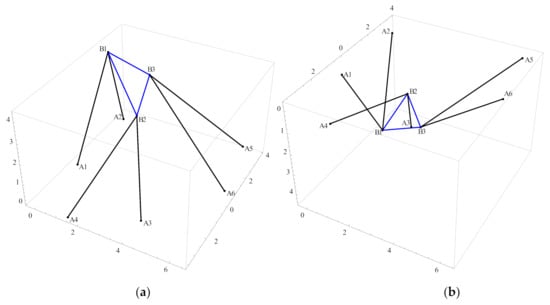
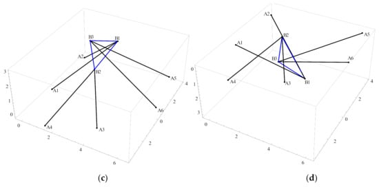
Figure 3.
Four assembly configurations (a, b, c, d) of 6-3 Stewart platforms.
6. Conclusions
In this paper, a novel geometric modeling and calculation method for closed-form solution of 6-3 Stewart platforms based on the framework of conformal geometric algebra is presented. Two formulas between 2-blade and 1-blade are first obtained. A 16-degree and coordinate-invariant polynomial equation by using the Euler angle substitution was derived without algebraic elimination. The final numerical results show that the proposed geometric modeling and calculation method is effective. Since the result obtained by the proposed method is a closed symbolic solution, the method is suitable to write the computer program. Compared with the existing methods for the forward displacement analysis of the 6-3 Stewart platforms, the highlight of this paper is that a new geometric modeling and calculation method without algebraic elimination is obtained by using the determinant form of CGA inner product algorithm (Equation (8)), which can be used for the forward displacement analysis of other complex parallel mechanisms. In addition, compared with [14] in the back substitution procedure, the proposed method does not need to determine the radical symbols.
Author Contributions
Conceptualization, G.Z.; Formal analysis, Y.Z.; Funding acquisition, S.W.; Investigation, Y.Z.; Methodology, G.Z.; Project administration, S.W.; Software, Q.L.; Supervision, Q.L.; Validation, G.Z.; Writing—original draft, G.Z.; Writing—review & editing, G.Z. All authors have read and agreed to the published version of the manuscript.
Funding
This research work is supported by the National Natural Science Foundation of China (No. 51605036) and the Beijing Municipal Natural Science Foundation (No. L172031).
Institutional Review Board Statement
Not applicable.
Informed Consent Statement
Not applicable.
Data Availability Statement
The data used to support the result of this study are obtained directly from the simulation by all authors.
Conflicts of Interest
The authors declare no conflict of interest.
Appendix A. Derivation of Equation (12)
Appendix B. Derivation of Equations (37)–(41)
According to Equations (19) and (23), we can obtain:
According Equation (8), the expansions of ,,, and are denoted as:
(1). The derivation of Equation (37):
(2). The derivation of Equation (38):
(3). The derivation of Equation (39):
(4). The derivation of Equation (40):
where
The expansions of ,, are simplified as:
According to Equations (A14)–(A16), the numerator and the denominator of Equation (A13) are divided by , we can obtain:
(5). The derivation of Equation (41):
where
The expansion of is simplified as:
where
The expansion of is simplified as:
where:
The expansion of is simplified as:
The expansion of is simplified as:
where , .
The expansion of is simplified as:
According to Equations (A19)–(A23), we can obtain:
The expansion of is simplified as:
The expansion of is simplified as:
The expansion of is simplified as:
The expansion of is simplified as:
According to the expressions of and Equations (A25)–(A28), the numerator and the denominator of Equation (A26) are divided by , we can obtain:
References
- Gough, V.E. Contribution to discussion of papers on research in automobile stability, control and tyre performance. Proc. Automot. Div. Inst. Mech. Eng. 1956, 171, 392–394. [Google Scholar]
- Stewart, D. A platform with six degree of freedom. Proceedings of the Institution of Mechanical Engineers. Part. I: J. Syst. Control. Eng. 1965, 180, 371–386. [Google Scholar]
- Luces, M.; Mills, J.K.; Benhabib, B. A Review of Redundant Parallel Kinematic Mechanisms. J. Intell. Robot. Syst. 2016, 86, 175–198. [Google Scholar] [CrossRef]
- Karger, A.; Husty, M. Classification of all self-motions of the original Stewart-Gough platform. Comput. Des. 1998, 30, 205–215. [Google Scholar] [CrossRef]
- Study, E. Geometrie der Dynamen—Die Zusammensetzung von Kraftenund verwandte Gegenstande der Geometrie, Leipzig, Verlag und Druck von B.G. Teubner, 1903. Math. Gaz. 1904, 3, 15–16. [Google Scholar]
- Ypma, T.J. Historical Development of the Newton–Raphson Method. Siam Rev. 1995, 37, 531–551. [Google Scholar] [CrossRef]
- Barton, M.; Shragai, N.; Elber, G. Kinematic Simulation of Planar and Spatial Mechanisms Using a Polynomial Constraints Solver. Comput. Des. Appl. 2009, 6, 115–123. [Google Scholar] [CrossRef][Green Version]
- Griffis, M.; Duffy, J. A forward displacement analysis of a class of stewart platforms. J. Robot. Syst. 1989, 6, 703–720. [Google Scholar] [CrossRef]
- Nanua, P.; Waldron, K.J.; Murthy, V. Direct kinematic solution of a Stewart platform. IEEE Trans. Robot. Autom. 1990, 6, 438–443. [Google Scholar] [CrossRef]
- Innocenti, C.; Parenti-Castelli, V. Direct position analysis of the Stewart platform mechanism. Mech. Mach. Theory 1990, 25, 611–621. [Google Scholar] [CrossRef]
- Merlet, J.-P. Direct kinematics and assembly modes of parallel manipulators. Int. J. Robot. Res. 1992, 11, 150–162. [Google Scholar] [CrossRef]
- Zhang, Y.; Liao, Q.; Wei, S.; Wei, F.; Li, D. A Novel Geometric Modeling and Solution Method for Forward Displacement Analysis of 6-3 Stewart Platforms. In Proceedings of the Lecture Notes in Electrical Engineering; Springer: Singapore, 2017; pp. 911–924. [Google Scholar]
- Wei, F.; Wei, S.; Zhang, Y.; Liao, Q. Forward Displacement Analysis of a General 6-3 Stewart Platform Using Conformal Geometric Algebra. Math. Probl. Eng. 2017, 2017 Pt 2, 1–9. [Google Scholar] [CrossRef]
- Zhang, Y.; Kong, X.; Wei, S.; Li, D.; Liao, Q. CGA-Based approach to direct kinematics of parallel mechanisms with the 3-RS structure. Mech. Mach. Theory 2018, 124, 162–178. [Google Scholar] [CrossRef]
- Li, H.; Hestenes, D.; Rockwood, A. Generalized Homogeneous Coordinates for Computational Geometry. In Geometric Computing with Clifford Algebras; Springer: Berlin/Heidelberg, Germany, 2001; pp. 27–59. [Google Scholar]
- Li, H. Conformal Geometric Algebra-A new framework for computational geometry. J. Comput. Aided Des. Comput. Graph. 2005, 17, 2383–2393. [Google Scholar]
- Rosenhahn, B.; Sommer, G. Pose Estimation in Conformal Geometric Algebra Part I: The Stratification of Mathematical Spaces. J. Math. Imaging Vis. 2005, 22, 27–48. [Google Scholar] [CrossRef]
- Hildenbrand, D.; Fontijne, D.; Perwass, C.; Dorst, L. Geometric algebra and its application to computer graphics. In Proceedings of the Euro Graphics 2004 Tutorial, Grenoble, France, 30 August–3 September 2004; pp. 1–49. [Google Scholar]
- Kim, J.S.; Jeong, J.H.; Park, J.H. Inverse kinematics and geometric singularity analysis of a 3-SPS/S redundant motion mechanism using conformal geometric algebra. Mech. Mach. Theory 2015, 90, 23–36. [Google Scholar] [CrossRef]
- Kleppe, A.L.; Egeland, O. Inverse Kinematics for Industrial Robots using Conformal Geometric Algebra. Model. Identif. Control. A Nor. Res. Bull. 2016, 37, 63–75. [Google Scholar] [CrossRef]
- Tørdal, S.S.; Hovland, G.; Yapin, I. Efficient Implementation of Inverse Kinematics on a 6-DOF Industrial Robot using Con-formal Geometric Algebra. Adv. Appl. Clifford Algebras 2017, 27, 2067–2082. [Google Scholar] [CrossRef]
- Song, Y.; Han, P.; Wang, P. Type synthesis of 1T2R and 2R1T parallel mechanisms employing conformal geometric algebra. Mech. Mach. Theory 2018, 121, 475–486. [Google Scholar] [CrossRef]
- Hrdina, J.; Návrat, A.; Vašík, P.; Matoušek, R. CGA-based robotic snake control. Adv. Appl. Clifford Algebras 2016, 27, 621–632. [Google Scholar] [CrossRef]
- Hrdina, J.; Návrat, A.; Vašík, P.; Matoušek, R. Geometric Control of the Trident Snake Robot Based on CGA. Adv. Appl. Clifford Algebras 2016, 27, 633–645. [Google Scholar] [CrossRef]
- Hrdina, J.; Návrat, A.; Vašík, P. Control of 3-Link Robotic Snake Based on Conformal Geometric Algebra. Adv. Appl. Clifford Algebras 2015, 26, 1069–1080. [Google Scholar] [CrossRef]
- Zhang, Y.; Liu, X.; Wei, S.; Wang, Y.; Zhang, X.; Zhang, P.; Liang, C. A Geometric Modeling and Computing Method for Direct Kinematic Analysis of 6-4 Stewart Platforms. Math. Probl. Eng. 2018, 2018 Pt 2, 1–9. [Google Scholar] [CrossRef]
- Huang, X.; Ma, C.; Su, H. A geometric algebra algorithm for the closed-form forward displacement analysis of 3-PPS parallel mechanisms. Mech. Mach. Theory 2019, 137, 280–296. [Google Scholar] [CrossRef]
Publisher’s Note: MDPI stays neutral with regard to jurisdictional claims in published maps and institutional affiliations. |
© 2021 by the authors. Licensee MDPI, Basel, Switzerland. This article is an open access article distributed under the terms and conditions of the Creative Commons Attribution (CC BY) license (http://creativecommons.org/licenses/by/4.0/).