
Comparative Evaluation for an Improved Direct Instantaneous Torque Control Strategy of Switched Reluctance Motor Drives for Electric Vehicles

 ,
,  ,
,  and
and
Abstract
:1. Introduction
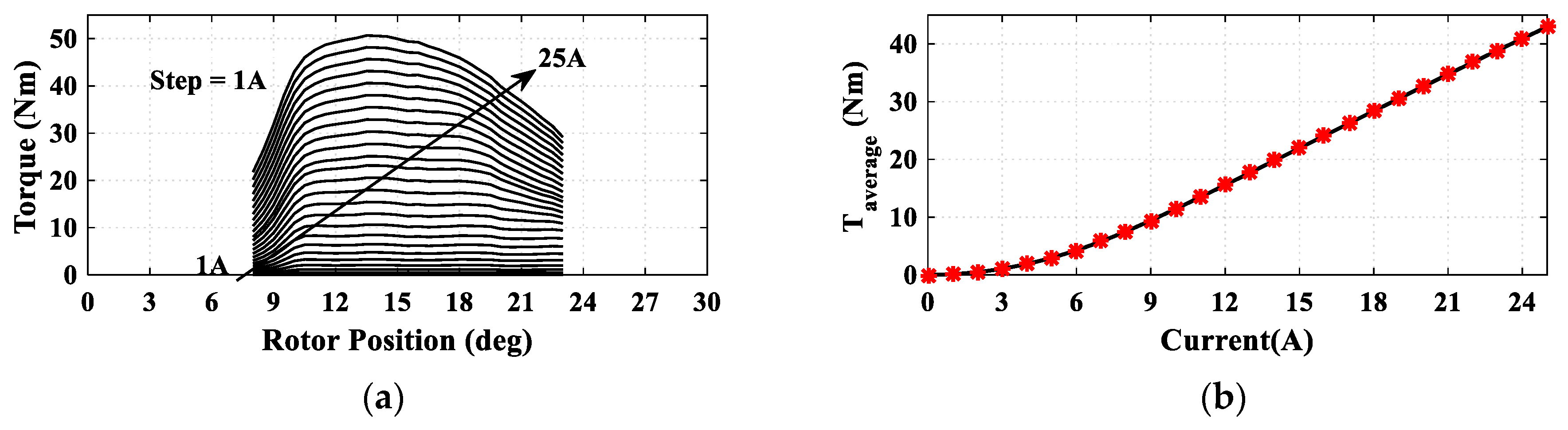
2. Machine Modeling
Performance Indices
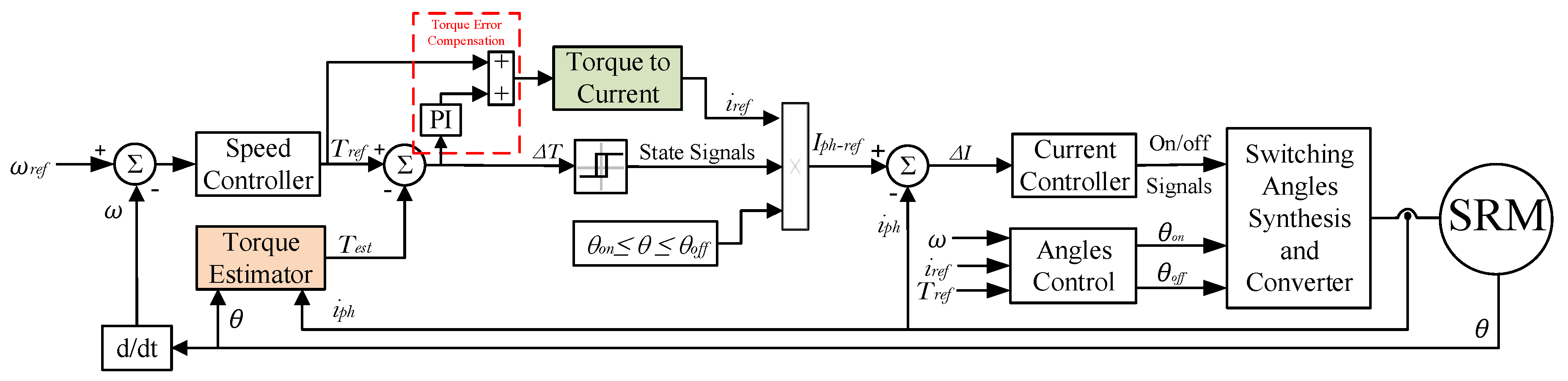
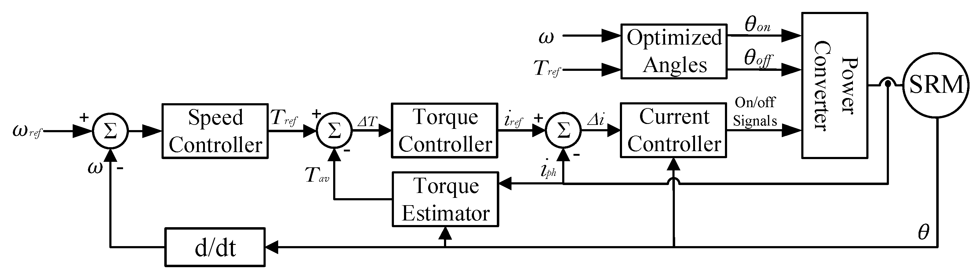
3. The Proposed Direct Instantaneous Torque Control (DITC)
3.1. Torque to Current Conversion
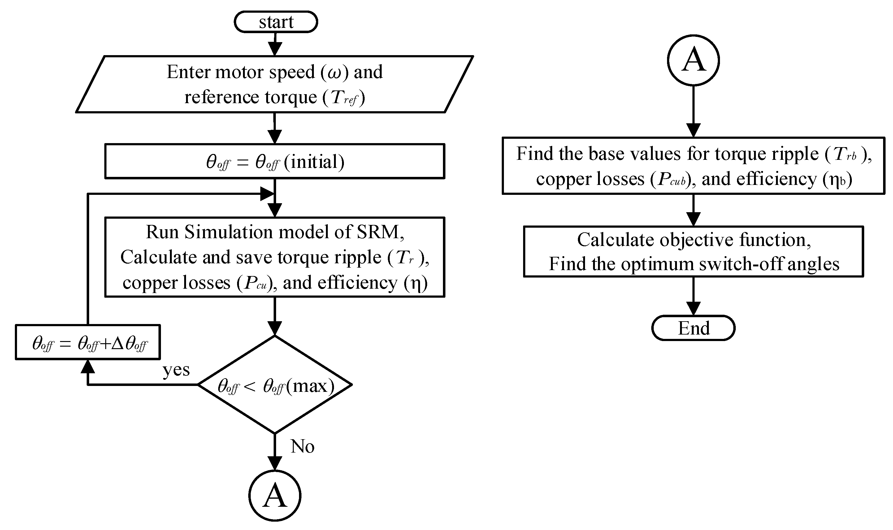
3.2. Switching Angles Optimization
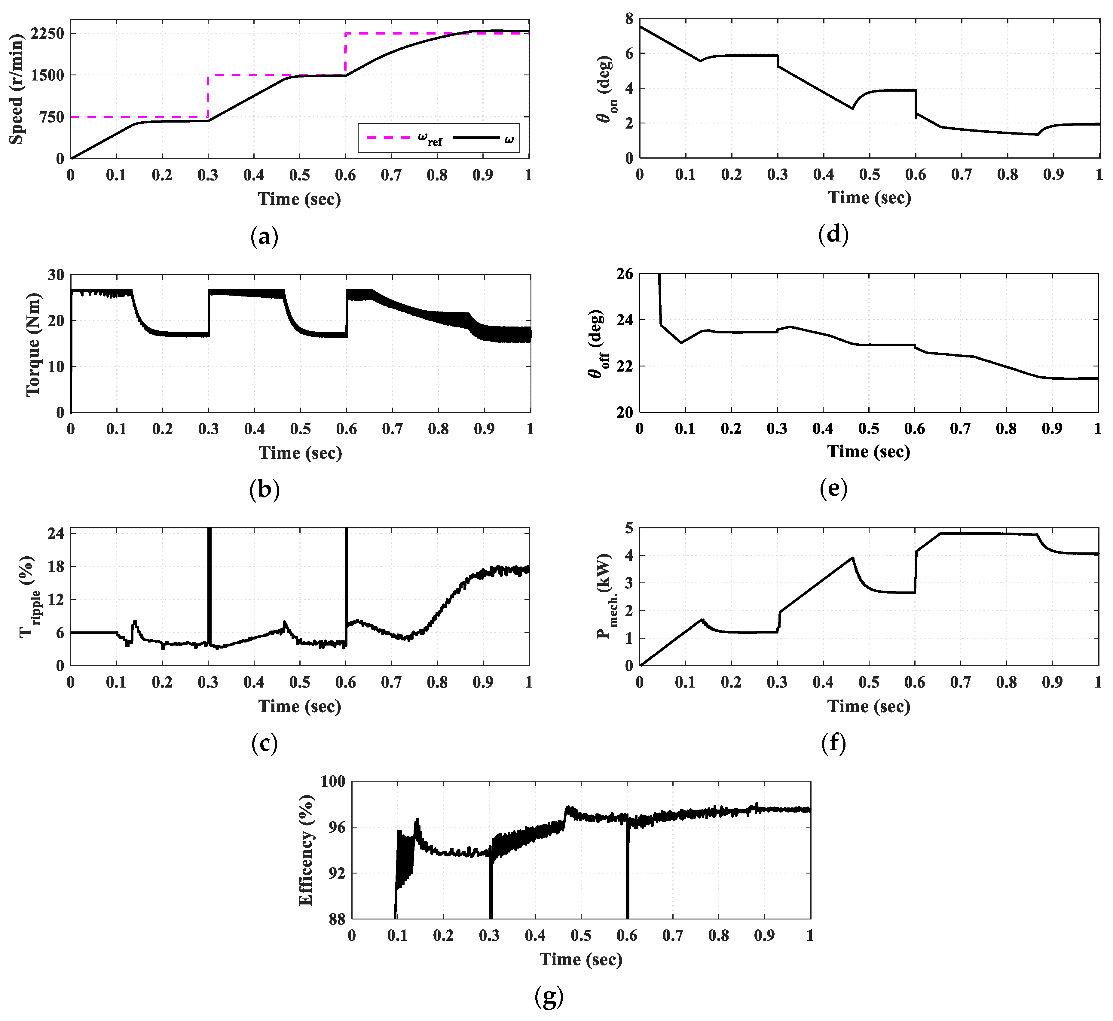
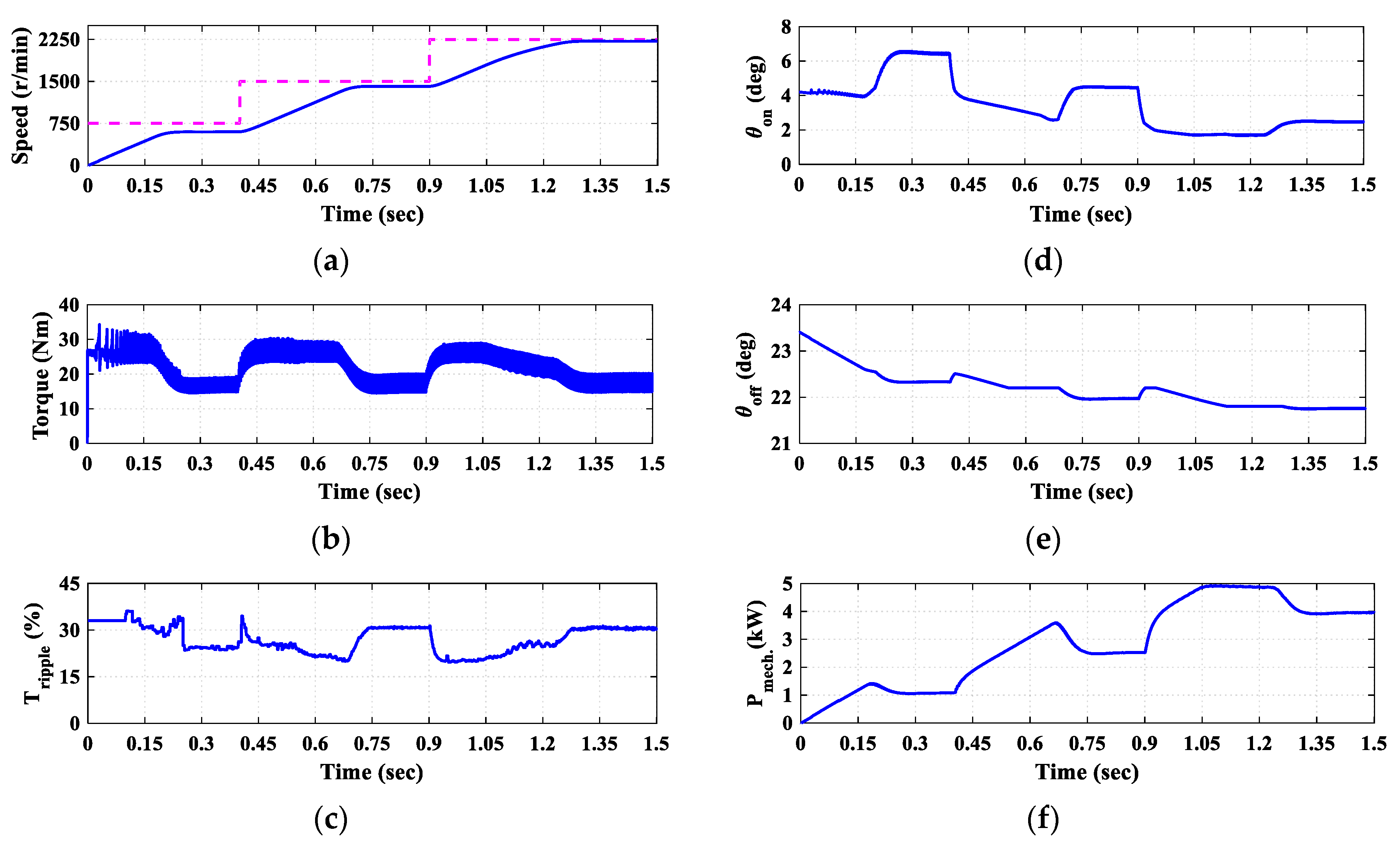
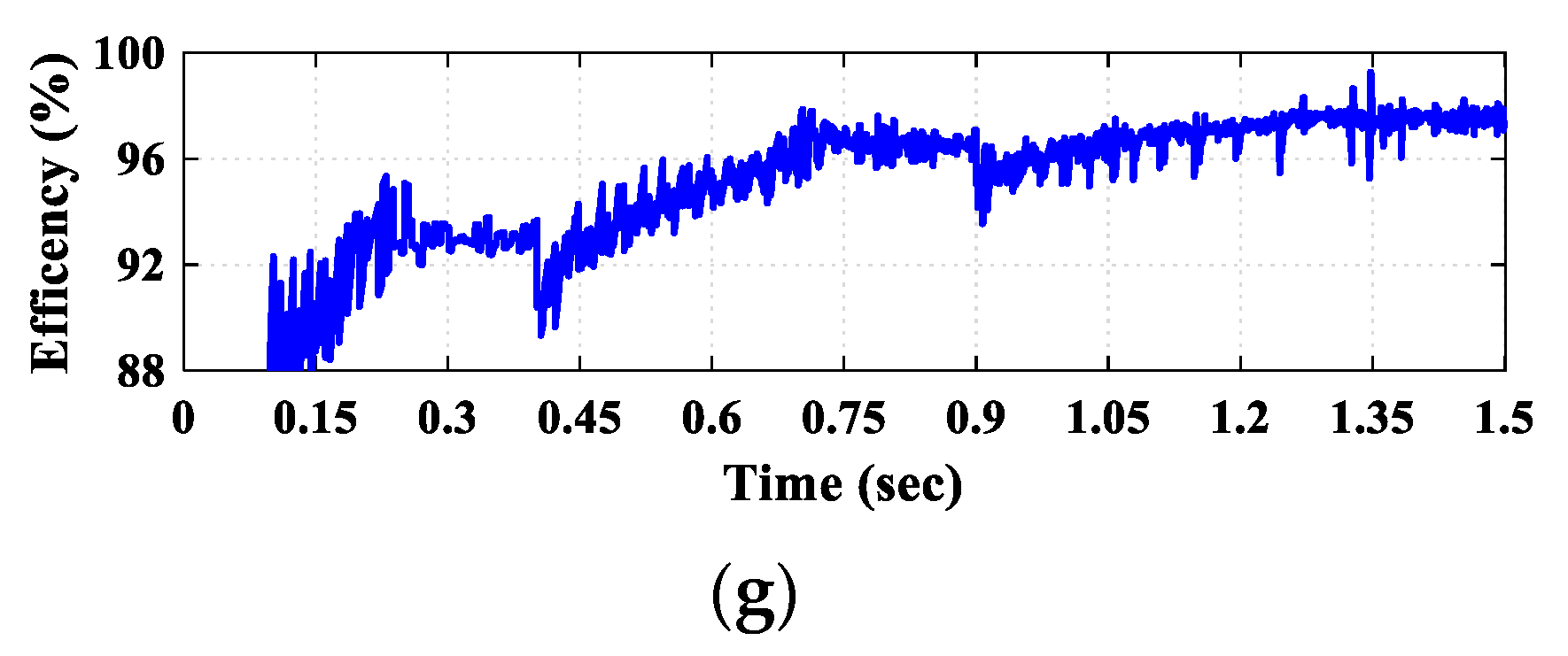
3.3. Simulation Results of the Proposed DITC
4. The Other Torque Control Techniques of SRM
4.1. Average Torque Control (ATC)
4.1.1. Switching Angles Optimization
4.1.2. Simulation Results of ATC
4.2. Indirect Instantaneous Torque Control (IITC)
Simulation Results of IITC
5. Comparative Analysis and Discussion
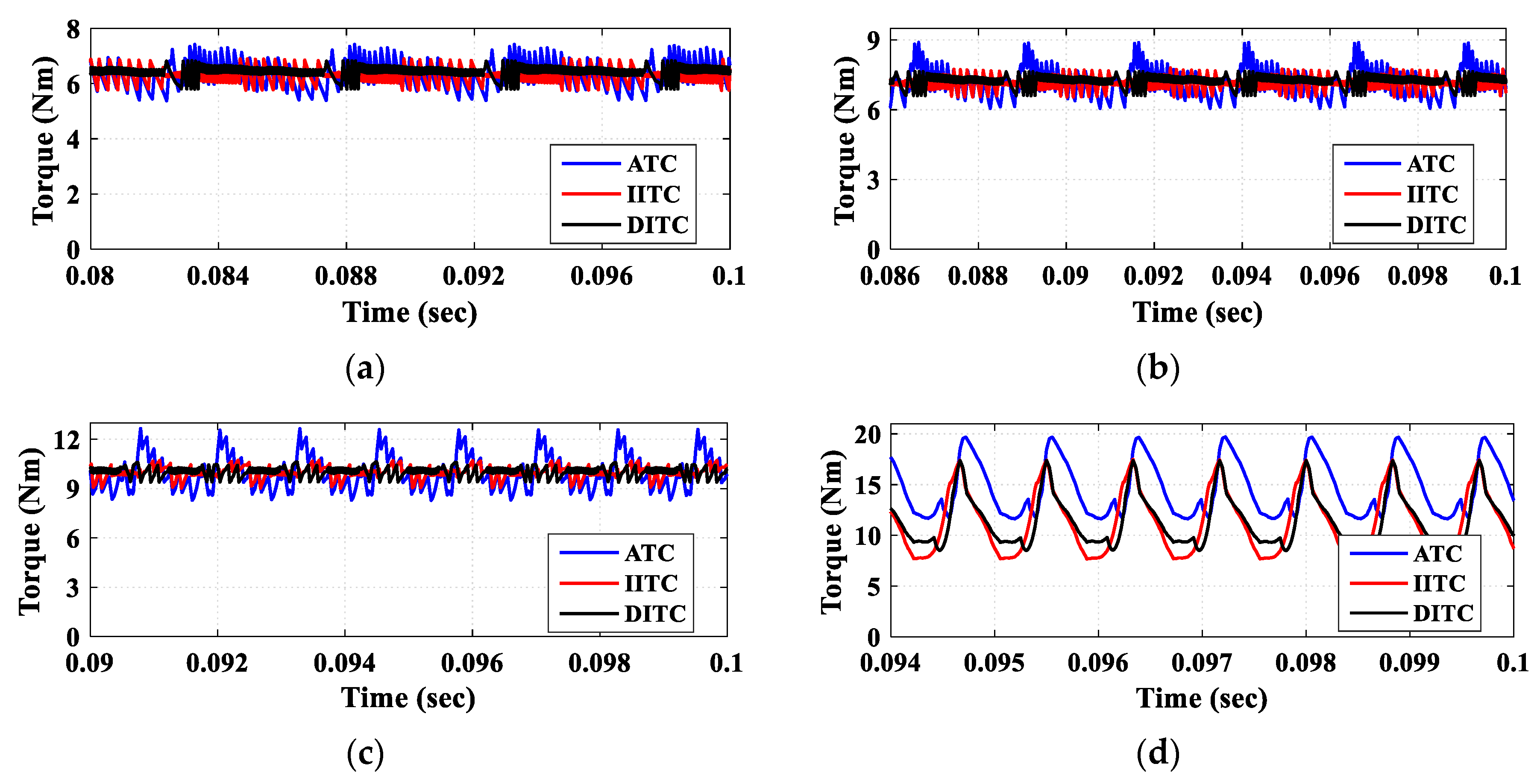
5.1. Under EV Loading
5.2. Under Full Load Conditions
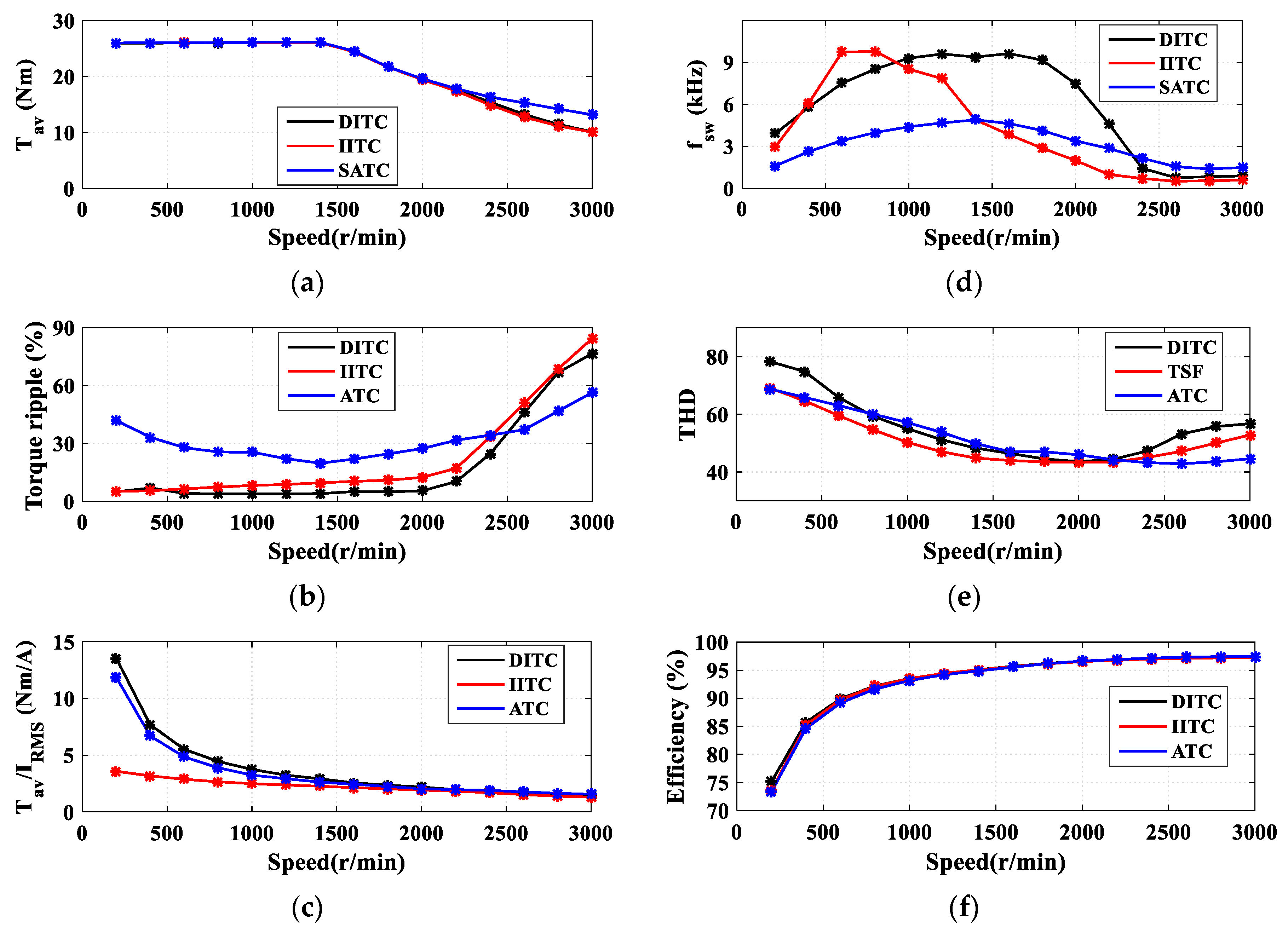
5.3. The Steady-State Torque Curves
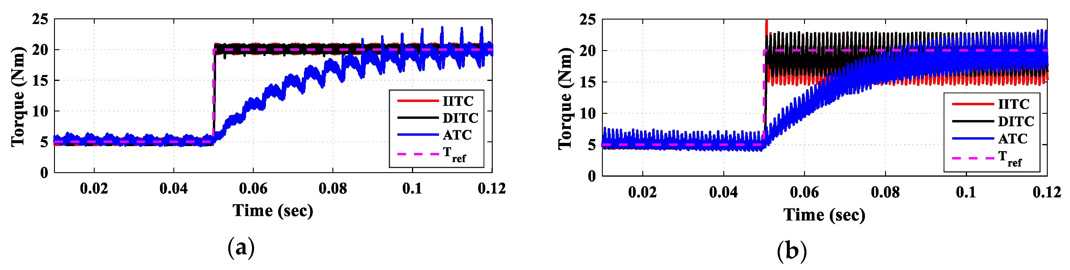
5.4. Dynamic Torque Response
6. Summary
7. Conclusions
Author Contributions
Funding
Conflicts of Interest
Abbreviation List
| ATC | Average torque control |
| DC | Direct current |
| DITC | Direct instantaneous torque control |
| DTC | Direct torque control |
| EVs | Electric vehicles |
| FEA | finite element analysis (FEA) |
| IITC | Indirect instantaneous torque control |
| ITC | Instantaneous torque control |
| MTPA | Maximum torque per ampere |
| PMs | Permanent magnets |
| RMS | Root Mean Square |
| SRM | Switched reluctance motor |
| THD | Total harmonic distortion |
| TSF | Torque sharing function |
References
- Chen, H.; Yan, W.; Gu, J.; Sun, M. Multiobjective Optimization Design of a Switched Reluctance Motor for Low-Speed Electric Vehicles with a Taguchi–CSO Algorithm. IEEE/ASME Trans. Mechatron. 2018, 23, 1762–1774. [Google Scholar] [CrossRef]
- Yueying, Z.; Chuantian, Y.; Yuan, Y.; Weiyan, W.; Chengwen, Z.; Zhu, Y.; Yang, C.; Yue, Y.; Wei, W.; Zhao, C. Design and optimisation of an In-wheel switched reluctance motor for electric vehicles. IET Intell. Transp. Syst. 2019, 13, 175–182. [Google Scholar] [CrossRef]
- Jiang, J.W.; Bilgin, B.; Emadi, A. Three-Phase 24/16 Switched Reluctance Machine for a Hybrid Electric Powertrain. IEEE Trans. Transp. Electrif. 2017, 3, 76–85. [Google Scholar] [CrossRef]
- Zhu, J.; Cheng, K.W.E.; Xue, X. Design and Analysis of a New Enhanced Torque Hybrid Switched Reluctance Motor. IEEE Trans. Energy Convers. 2018, 33, 1965–1977. [Google Scholar] [CrossRef]
- Bartolo, J.B.; Degano, M.; Espina, J.; Gerada, C. Design and Initial Testing of a High-Speed 45-kW Switched Reluctance Drive for Aerospace Application. IEEE Trans. Ind. Electron. 2017, 64, 988–997. [Google Scholar] [CrossRef]
- Mousavi-Aghdam, S.R.; Feyzi, M.R.; Bianchi, N.; Morandin, M. Design and Analysis of a Novel High-Torque Stator-Segmented SRM. IEEE Trans. Ind. Electron. 2016, 63, 1458–1466. [Google Scholar] [CrossRef]
- Nam, K.H. AC Motor Control and Electrical Vehicle Applications; CRC Press Taylor & Francis Group: Boca Raton, FL, USA, 2019. [Google Scholar]
- Ehsani, M.; Gao, Y.; Emadi, A. Modern Electric, Hybrid Electric, and Fuel Cell Vehicles: Fundamentals, Theory, and Design; CRC Press: Boca Raton, FL, USA, 2010. [Google Scholar]
- Husain, T.; Elrayyah, A.; Sozer, Y.; Husain, I. Unified Control for Switched Reluctance Motors for Wide Speed Operation. IEEE Trans. Ind. Electron. 2019, 66, 3401–3411. [Google Scholar] [CrossRef]
- Husain, T.; Elrayyah, A.; Sozer, Y.; Husain, I. An efficient universal controller for switched-reluctance machines. In Proceedings of the 2013 28th Annual IEEE Applied Power Electronics Conference and Exposition (APEC), Long Beach, CA, USA, 17–21 March 2013; pp. 1530–1536. [Google Scholar]
- Gan, C.; Wu, J.; Sun, Q.; Kong, W.; Li, H.; Hu, Y. A Review on Machine Topologies and Control Techniques for Low-Noise Switched Reluctance Motors in Electric Vehicle Applications. IEEE Access 2018, 6, 31430–31443. [Google Scholar] [CrossRef]
- Mikail, R.; Husain, I.; Sozer, Y.; Islam, M.S.; Sebastian, T. Torque-Ripple Minimization of Switched Reluctance Machines Through Current Profiling. IEEE Trans. Ind. Appl. 2013, 49, 1258–1267. [Google Scholar] [CrossRef]
- Shaked, N.; Rabinovici, R. New procedures for minimizing the torque ripple in switched reluctance motors by optimizing the phase-current profile. IEEE Trans. Magn. 2005, 41, 1184–1192. [Google Scholar] [CrossRef]
- Ye, J.; Bilgin, B.; Emadi, A. An Offline Torque Sharing Function for Torque Ripple Reduction in Switched Reluctance Motor Drives. IEEE Trans. Energy Convers. 2015, 30, 726–735. [Google Scholar] [CrossRef]
- Ye, J.; Bilgin, B.; Emadi, A. An Extended-Speed Low-Ripple Torque Control of Switched Reluctance Motor Drives. IEEE Trans. Power Electron. 2015, 30, 1457–1470. [Google Scholar] [CrossRef]
- Suebsuang, P.J.S. An adaptive low-ripple torque control of switched reluctance motor for small electric vehicle. In Proceedings of the International Conference on Electrical Machines and Systems, Wuhan, China, 17–20 October 2008; pp. 3327–3332. [Google Scholar]
- Chithrabhanu, A.; Vasudevan, K. Online compensation for torque ripple reduction in SRM drives. In Proceedings of the IEEE Transportation Electrification Conference (ITEC-India), Chicago, IL, USA, 22–24 June 2017; pp. 1–6. [Google Scholar]
- Shirahase, M.; Morimoto, S.; Sanada, M. Torque ripple reduction of SRM by optimization of current reference. In Proceedings of the International Power Electronics Conference—ECCE ASIA, Sapporo, Japan, 21–24 June 2010; pp. 2501–2507. [Google Scholar]
- Nasirian, V.; Kaboli, S.; Davoudi, A.; Moayedi, S. High-Fidelity Magnetic Characterization and Analytical Model Development for Switched Reluctance Machines. IEEE Trans. Magn. 2012, 49, 1505–1515. [Google Scholar] [CrossRef]
- Hamouda, M.; Szamel, L. Torque Control of Switched Reluctance Motor Drives for Electric Vehicles. In Proceedings of the Automation and Applied Computer Science Workshop, Budapest, Hungary, 16 June 2017; pp. 9–20. [Google Scholar]
- Jamil, M.U.; Kongprawechnon, W.; Chayopitak, N. Average Torque Control of a Switched Reluctance Motor Drive for Light Electric Vehicle Applications. IFAC PapersOnLine 2017, 50, 11535–11540. [Google Scholar] [CrossRef]
- Cheng, H.; Chen, H.; Yang, Z. Average torque control of switched reluctance machine drives for electric vehicles. IET Electr. Power Appl. 2015, 9, 459–468. [Google Scholar] [CrossRef]
- Petrus, V.; Pop, V.; Gyselinck, A.-C.; Martis, J.; Iancu, C. Average Torque Control of an 8/6 Switched Reluctance Machine for Electric Vehicle Traction. J. Comput. Sci. Control Syst. 2012, 5, 59. [Google Scholar]
- Bose, B.K.; Miller, T.J.E.; Szczesny, P.M.; Bicknell, W.H. Microcomputer Control of Switched Reluctance Motor. IEEE Trans. Ind. Appl. 1986, 22, 708–715. [Google Scholar] [CrossRef]
- Xue, X.D.; Cheng, K.W.E.; Lin, J.K.; Zhang, Z.; Luk, K.F.; Ng, T.W.; Cheung, N.C. Optimal Control Method of Motoring Operation for SRM Drives in Electric Vehicles. IEEE Trans. Veh. Technol. 2010, 59, 1191–1204. [Google Scholar] [CrossRef]
- Nguyen, D.-M.; Bahri, I.; Krebs, G.; Berthelot, E.; Marchand, C.; Ralev, I.V.; Burkhart, B.; De Doncker, R.W. Efficiency Improvement by the Intermittent Control for Switched Reluctance Machine in Automotive Application. IEEE Trans. Ind. Appl. 2019, 55, 4167–4182. [Google Scholar] [CrossRef]
- Inderka, R.; De Doncker, R. DITC-direct instantaneous torque control of switched reluctance drives. IEEE Trans. Ind. Appl. 2003, 39, 1046–1051. [Google Scholar] [CrossRef]
- Fuengwarodsakul, N.; Menne, M.; Inderka, R.; De Doncker, R. High-Dynamic Four-Quadrant Switched Reluctance Drive Based on DITC. IEEE Trans. Ind. Appl. 2005, 41, 1232–1242. [Google Scholar] [CrossRef]
- Chancharoensook, P. Direct instantaneous torque control of a four-phase switched reluctance motor. In Proceedings of the International Conference on Power Electronics and Drive Systems (PEDS), Taipei, Taiwan, 2–5 November 2009; pp. 770–777. [Google Scholar]
- Castro, J.; Andrada, P.; Blanqué, B. Minimization of torque ripple in switched reluctance motor drives using an enhanced direct instantaneous torque control. In Proceedings of the XXth International Conference on Electrical Machines, Marseille, France, 2–5 September 2012; pp. 1021–1026. [Google Scholar]
- Kianinezhad, M.M.B.M.S.R. Direct Instantaneous Torque Control of Switched Reluctance Motors Using Five Level Converter. In Proceedings of the 46th International Universities Power Engineering Conference, Soest, Germany, 5–8 September 2011. [Google Scholar]
- Yang, Q.; Ma, M.; Chang, Z.; Zhang, X.; Lin, Z. Direct instantaneous torque control of switched reluctance motor with three-bridge five-level converter. PEMD 2016, 2016, 574. [Google Scholar] [CrossRef]
- Song, S.; Peng, C.; Guo, Z.; Ma, R.; Liu, W. Direct Instantaneous Torque Control of Switched Reluctance Machine Based on Modular Multi-Level Power Converter. In Proceedings of the 22nd International Conference on Electrical Machines and Systems (ICEMS), Harbin, China, 11–14 August 2019. [Google Scholar]
- Sun, Q.; Wu, J.; Gan, C. Optimized Direct Instantaneous Torque Control for SRMs with Efficiency Improvement. IEEE Trans. Ind. Electron. 2020, 68, 1. [Google Scholar] [CrossRef]
- Sandre-Hernandez, O.; Rangel-Magdaleno, J.D.J.; Morales-Caporal, R. A Comparison on Finite-Set Model Predictive Torque Control Schemes for PMSMs. IEEE Trans. Power Electron. 2018, 33, 8838–8847. [Google Scholar] [CrossRef]
- Hamouda, M.; Számel, L. Accurate Magnetic Characterization Based Model Development for Switched Reluctance Machine. Period. Polytech. Electr. Eng. Comput. Sci. 2019, 63, 202–212. [Google Scholar] [CrossRef]
- Hamouda, M.; Számel, L. A new technique for optimum excitation of switched reluctance motor drives over a wide speed range. Turk. J. Electr. Eng. Comput. Sci. 2018, 26, 2753–2767. [Google Scholar] [CrossRef]


| Indices | Low Speed | ||
|---|---|---|---|
| DITC | IITC | ATC | |
| Algorithm complexity | Moderate | Complex | Complex |
| Requirement of torque inverse model | No | Yes | No |
| Dynamic torque response | Fast | Fast | Slow |
| Requirement of online torque estimation | Yes | Yes | Yes |
| Required control period | Short | Short | Long |
| Indices | Low Speed | High Speed | ||||
|---|---|---|---|---|---|---|
| DITC | IITC | ATC | DITC | IITC | ATC | |
| Average torque | High | High | High | Low | Low | High |
| Torque ripple | Low | Medium | High | Medium | Medium | Low |
| Switching frequency | High | Medium | Low | Medium | Low | High |
| Torque/current ratio | High | Low | Medium | High | Low | High |
| THD | Medium | Low | High | High | Medium | Low |
| Flux derivatives | Low | High | Low | Low | High | High |
| Efficiency | High | Medium | High | Medium | Medium | High |
Publisher’s Note: MDPI stays neutral with regard to jurisdictional claims in published maps and institutional affiliations. |
© 2021 by the authors. Licensee MDPI, Basel, Switzerland. This article is an open access article distributed under the terms and conditions of the Creative Commons Attribution (CC BY) license (http://creativecommons.org/licenses/by/4.0/).
Share and Cite
Hamouda, M.; Abdel Menaem, A.; Rezk, H.; Ibrahim, M.N.; Számel, L. Comparative Evaluation for an Improved Direct Instantaneous Torque Control Strategy of Switched Reluctance Motor Drives for Electric Vehicles. Mathematics 2021, 9, 302. https://doi.org/10.3390/math9040302
Hamouda M, Abdel Menaem A, Rezk H, Ibrahim MN, Számel L. Comparative Evaluation for an Improved Direct Instantaneous Torque Control Strategy of Switched Reluctance Motor Drives for Electric Vehicles. Mathematics. 2021; 9(4):302. https://doi.org/10.3390/math9040302
Chicago/Turabian StyleHamouda, Mahmoud, Amir Abdel Menaem, Hegazy Rezk, Mohamed N. Ibrahim, and László Számel. 2021. "Comparative Evaluation for an Improved Direct Instantaneous Torque Control Strategy of Switched Reluctance Motor Drives for Electric Vehicles" Mathematics 9, no. 4: 302. https://doi.org/10.3390/math9040302
APA StyleHamouda, M., Abdel Menaem, A., Rezk, H., Ibrahim, M. N., & Számel, L. (2021). Comparative Evaluation for an Improved Direct Instantaneous Torque Control Strategy of Switched Reluctance Motor Drives for Electric Vehicles. Mathematics, 9(4), 302. https://doi.org/10.3390/math9040302