Article

Inverter Volt-Ampere Capacity Reduction by Optimization of the Traction Synchronous Homopolar Motor

by
Vladimir Prakht
1,*,
Vladimir Dmitrievskii
1,
Alecksey Anuchin
2 and
Vadim Kazakbaev
1
1
Department of Electrical Engineering, Ural Federal University, 620002 Yekaterinburg, Russia
2
Department of Electric Drives, Moscow Power Engineering Institute, 111250 Moscow, Russia
*
Author to whom correspondence should be addressed.
Mathematics 2021, 9(22), 2859; https://doi.org/10.3390/math9222859
Submission received: 10 October 2021 / Revised: 3 November 2021 / Accepted: 9 November 2021 / Published: 11 November 2021

Abstract

:
The synchronous homopolar motor (SHM) with an excitation winding on the stator and a toothed rotor is a good alternative to traction induction motors for hybrid mining trucks. The main problem in the design of the SHM electric drives is that the magnetic flux forms three-dimensional loops and, as a result, the lack of high-quality optimization methods, which leads to the need to overrate the installed power of the inverter. This article discusses the procedure and results of optimization of a commercially available 370 kW traction SHM using the Nelder–Mead method. The objective function is composed to mainly improve the following characteristics of the traction SHM: total motor power loss and maximum armature winding current. In addition, terms are introduced into the objective function to make it possible to limit the voltage, the loss in the excitation winding, and the maximum magnetic flux density in the non-laminated sections of the magnetic core. As a result of the optimization, the motor losses and the maximum current required by the motor from the inverter were significantly reduced. The achieved reduction in the maximum current allows the cost of the IGBT modules of the inverter to be reduced by 1.4 times (by $ 2295), and also allows the AC component of the DC-link current to be reduced by the same amount.

1. Introduction

Synchronous homopolar machines (SHMs) with an excitation winding on the stator are used in a number of applications, such as aircraft and ground vehicle generators, welding generators, and flywheel energy storage devices [1,2,3]. The main advantages of the SHM are the structural simplicity of the toothed rotor and the high reliability of the machine as a whole due to the absence of an excitation winding or a squirrel cage on the rotor. A number of studies have proposed the use of SHM in traction applications, due to the disadvantages of induction motors commonly used in these applications, such as the low reliability of the welded rotor cage, high rotor losses, difficulties in sensorless control, and difficulty of employing pure electric brakes at zero rotational speed due to the thermal cycling of the inverter semiconducting devices [3]. The complex design of the magnetic core causes difficulties in using traditional 2D FEM models to assess the performances of the SHM. For this reason, a number of original calculation methods have been proposed for the SHM, including 3D FEM, 2D FEM, one-dimensional magnetic circuits, and their various combinations [4,5,6,7]. In [3], a method for mathematical optimization of the traction SHM was proposed. It has been shown that by applying optimization, it is possible to significantly reduce the losses and torque ripple of the SHM. However, in [3], the current of the armature winding was not reduced sufficiently during the optimization to allow a reduction of the power rating and the cost of the traction inverter.
In this study, compared with [3], the objective optimization function is modified to significantly reduce the armature winding current and, as a result, to use cheaper IGBT modules (650 A) compared to those in the non-optimized SHM (1000 A). At the optimization, the restrictions imposed by the standard cross-sections of rectangular winding wires are taken into account. Additionally, the optimization was aimed at the total power loss reduction.
The one-criterion Nelder–Mead method is applied in this work to optimize the SHM design. An important advantage of the Nelder–Mead method over other methods that are often used to optimize electrical machines [8,9] is the significant savings in computational time, which makes it possible to increase the number of parameters to optimize, as well as to apply more complex optimization criteria, for the calculation of which it is necessary to calculate several load points of the machine [10]. This advantage is important for optimizing traction machines with a wide speed control range.

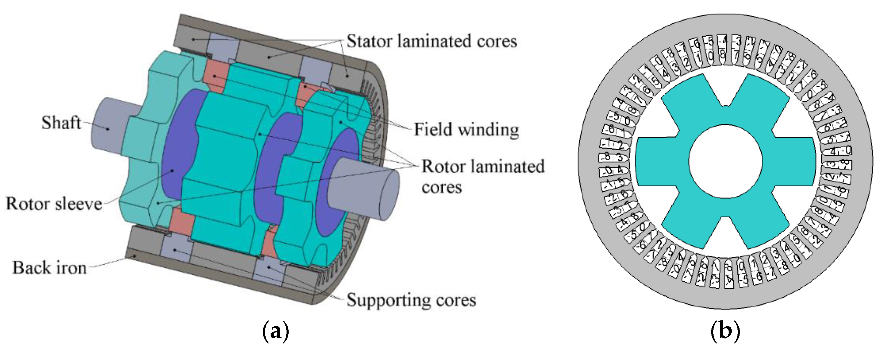
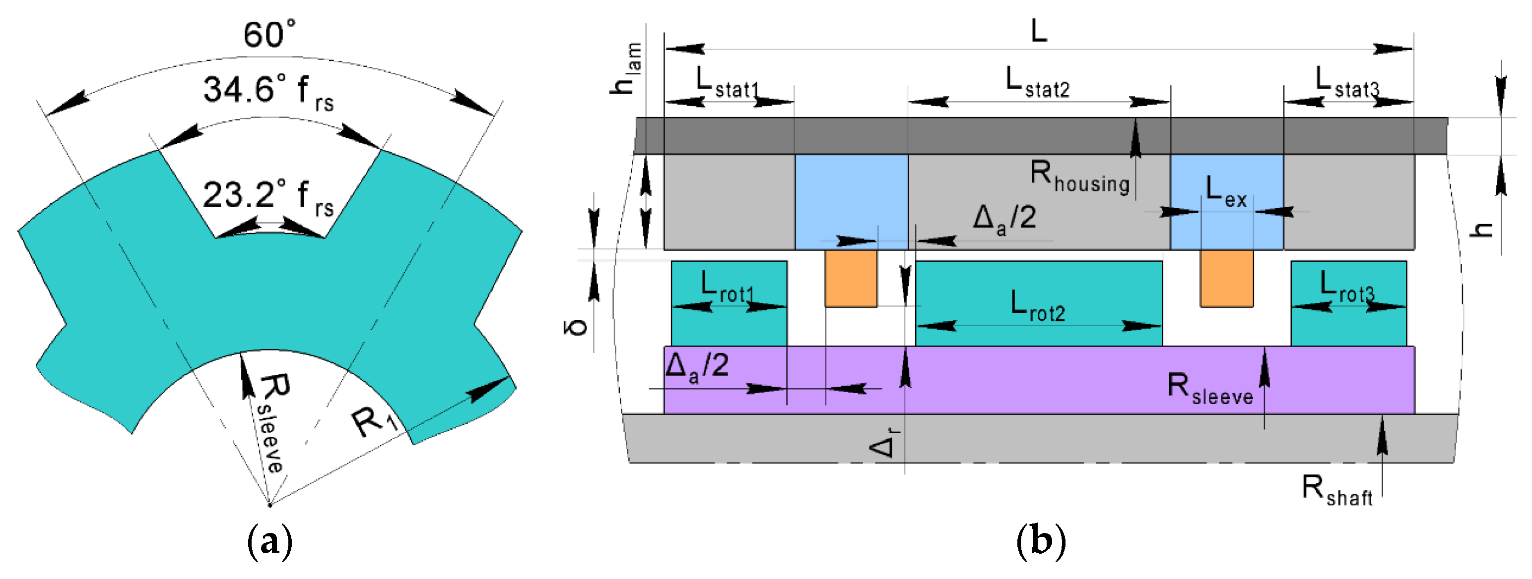
2. Geometry of the Traction SHM

Figure 1 shows the sketches of the nine-phase traction SHM. The machine has three sets of stacks on the stator and on the rotor. A nine-phase six-pole armature winding is placed on the stator. An excitation winding consisting of two coils is placed between the stator stacks. The stator has 54 slots. The rotor has no windings. Each rotor stack has 6 teeth, and the teeth of adjacent rotor stacks are offset by 30 mechanical degrees. In Figure 2a, the dependence of the maximal torque on the rotational speed of the electric drive of the BELAZ 75570 mining dump truck is shown. Figure 2b demonstrates the circuit of the nine-phase traction SHM inverter. The SHM traction inverter consists of three individual three-bridge inverters and a single-phase breaker for the supply of the excitation winding [4]. A more detailed description of the nine-phase traction SHM and the inverter is given in [4,11].

3. Objective Function for Optimizing the Traction SHM

Figure 2b shows the required torque-speed characteristic of the rear wheel drive of the considered truck [4]. The traction drive must provide the maximum torque of 8833 N∙m from zero (standstill) to the rated speed of 400 rpm. In the speed range of 400 rpm and above, the drive must be capable of producing power of at least 370 kW. The maximum required rotation speed while maintaining the mechanical power of 370 kW is 4000 rpm. Table 1 indicates the motor operating points considered in the optimization procedure: maximum torque at rated speed, rated power at maximum speed, and an intermediate point with geometric mean values of the torque and speed.
In [3], during the optimization of the traction SHM, it was possible to significantly reduce the motor losses, and the torque ripple in comparison with the non-optimized SHM [4]. The line voltage is reduced from 940 to 772 V. However, the peak armature current was reduced only slightly (from 886 to 816 A). Therefore, it is necessary to use the inverter with IGBT modules FF1000R17IE4 [12] with a rated current of 1000 A for both the non-optimized SHM [4] and the optimized SHM.
The aim of this paper is to demonstrate the possibility of using the cheaper and less powerful power module FF650R17IE4 [13] for the considered powertrain. For this purpose, it is necessary to increase the number of turns of the stator winding and change the geometry of the slot. At the same time, the maximum voltage limitation constraint must be set.
Therefore, when optimizing the traction SHM in this study, the following main goals were set: (1) the armature winding current must be significantly reduced; this will make it possible to switch to cheaper power IGBT modules FF650R17IE4 [13] in the inverter; (2) the amplitude of the voltage must not exceed 1000 V; and (3) it is necessary to reduce the total motor losses in comparison with the non-optimized design of the SHM [3].
When estimating the motor losses, ranges 1–2 and 2–3 on the motor torque-speed curve (Figure 2a) are considered. It is assumed that average losses in the ranges are equal to the arithmetic mean of the losses at their boundaries (points 1 and 2 and points 2 and 3, respectively) and that the motor will be equally likely to run between the points 1 and 2 and between points 2 and 3 on its torque–speed curve. For this reason, the weighted average losses were chosen as the first optimization objective:
<Plosses> = (Plosses1 + 2∙Plosses2 + Plosses3)/4.
The motor torque ripples were also chosen as an optimization objective. Both non-symmetrized (created by one combination of rotor and stator stacks) TR and symmetrized (created by a whole motor consisting of three combinations of stator and rotor stacks) torque ripple TRsym are considered [3]. The last optimization objective is the maximum armature winding current I3 that is achieved at the maximum torque (operating point 3). Taking into account all the objectives, the motor optimization function is formulated as:
F0 = ln(<Plosses>) + 0.7 ln(I3) + 0.05∙ln[max(TRsym)] + 0.025∙ln[max(TR)].
Formula (2) suggests that <Plosses> is the most valuable objective. The second most important objective is I3. A 1% decrease in I3 is as valuable as a 0.7% decrease in <Plosses>. The decrease in max(TRsym) and max(TR) is not so significant. Decreasing max(TRsym) and max(TR) by 1% is just as important as decreasing <Plosses> by 0.05% and 0.025%, respectively. However, including the max(TRsym) and max(TR) terms allows the increase in motor torque ripple during optimization to be limited.
The optimization procedure also takes into account the following constraints:
UDC1 < 1000 V; B3 < 1.65 T; Pexc < 12,000 W,
where UDC1 is the maximum voltage reached at the maximum speed (operating point 1), Pexc is the power loss in the excitation winding, and B3 is the maximum flux density in the non-laminated sections of the magnetic circuit (the rotor sleeve and the motor housing).
The optimization procedure is based on the one-criterion unconstrained Nelder–Mead method. There are various ways to implement constraints when using the Nelder–Mead method. For example, an objective function can take an infinite value when constraints are not met. However, this approach leads to a rapid decrease in the volume of the simplex. Additionally, constraints (3) should be satisfied in the initial design and along the optimization. To avoid these drawbacks, the ‘soft constraints’ are applied to the objective function (2). The constraining terms begin to increase rapidly if constraints are not met:
F = F 0 + k 1 × f ( U D C 1 / 1000 [ V ] 1 ) + k 2 × f ( B 3 / 1.65 [ T ] 1 ) + k 3 × f ( P e x c / 12 , 000 [ W ] 1 ) , where   f ( x ) = { x , x > 0 0 .
As a consequence, the objective function allows constraints to be violated in order to prevent a rapid decrease in the volume of the simplex. However, as it will be shown below, the optimized design will still satisfy constraints (3), if the factors k1, k2, and k3 are large enough (exceed the corresponding Lagrange multipliers). In this study, it is assumed that k1 = k2 = k3 = 1.5. Due to the choice of the objective function (4), the choice of the initial approximation is not limited by constraints (3). As will be seen below, constraints (3) will be violated in the initial approximation.

4. Initial Design Parameters and Variable Parameters Used for Optimizing the Traction SHM

Figure 3 shows the main geometric parameters of the non-optimized traction SHM [4]. The parameters that are fixed and varied during optimization are shown in Table 2 and Table 3, correspondingly. The outer dimensions of the motor (the length of the motor without winding end parts L = 545 mm and the stator housing outer radius Rhousing = 367 mm) did not change during optimization. The rotor yoke thickness and the stator stack height were also not varied. Due to the fact that the outer radius of the stator housing Rhousing remains constant, the inner radius of the stator changes as the thickness h of the stator housing changes. The outer radius of the rotor also depends on the width of the air gap δ. To ensure equal conditions of flow of the excitation magnetic flux in the axial direction through the stator housing and the rotor sleeve, the areas of their cross-sections are assumed to be equal.
As a result, the outer radius of the rotor sleeve is determined by formula:
Rsleeve = √(Rshaft2 + Rhousing2 − [Rhousingh]2).
In [4], Rsleeve equals 161 mm, while (5) provides Rsleeve = 167 mm. Since the thickness of the rotor yoke R1Rsleeve is not varied, the depth of the rotor slot changes not only with a change in the outer diameter of the rotor, but also with Rsleeve.
Variation of the angular dimensions between the rotor teeth along the rotor inner radius and along the rotor outer radius was carried out in concert by multiplying both dimensions by the coefficient frs. The excitation winding resistance is 10.2 Ohms in [4]. The longitudinal and radial dimensions occupied by the excitation winding between two stator stacks are Lex = 43 mm and hexc = 78 mm [3]. During the optimization, Lex = (LLstat)/2 − Δa changed along with the Lstat variation. hexc = RhousinghhlamRsleeve − Δr changed due to the variation in h, as well as due to the variation in Rsleeve which is a function of h (5). The resistance of the excitation winding changes with the dimensions of the field winding as 10.2 Ohm × 43 mm × 78 mm/hexc/Lex. The number of turns of the excitation winding is equal to 340 and assumed to be unchanged. In this study, the number of turns of the armature winding increased for better utilization of the supply voltage, which results in an increased height of the stator slots and decreased thickness of the stator lamination yoke. To restrict the growth of the stator slots, the thinner winding was chosen. The winding details are provided in Table 4. The main characteristics of the motor prototype described in [4] are shown on the left side of Table 5. The main characteristics of the motor obtained after the above changes (initial design) are shown on the right side of Table 5.
Therefore, according to (5), the drop of the excitation magnetomotive force (MMF) on the rotor sleeve is reduced due to the increase in Rsleeve, in comparison with [3]. On the other hand, the depth of the rotor slots and the rotor saliency decrease. The resistance of the excitation winding also changes. In addition, the initial design used as a starting point for optimization differs from [3] in the parameters of the armature winding as Table 4 indicates. As can be seen from Table 5, the change in the parameters of the armature winding shown in Table 4 led to a significant increase in the line voltage up to 1303 V at the first operating point. This voltage value significantly exceeds the maximum allowable voltage in the DC-link of the mining dump truck power supply and cannot be implemented in practice. However, in the next section it will be shown that, using the objective function (4) and the Nelder–Mead method, it is possible to significantly improve all the main characteristics of the SHM without exceeding the voltage limit of 1000 V.

5. Optimization of Traction HSM Using the Nelder–Mead Method

The traditional Nelder–Mead algorithm [14], the 2-D FEM based mathematical model of the SHM, according to [4], and the objective function (4) were used in the SHM optimization process. This optimization was applied to the new initial design with a larger number of turns and a modified stator slot shape (see Table 4) to further reduce the armature winding current and comply with the maximum voltage limitation simultaneously.
The optimization procedure varied the 10 SHM parameters listed in Table 2. Figure 4 shows the cross-section of the motor and the magnitude of the magnetic flux density before and after optimization at the operating point 3 (see Table 1) with the maximum torque and the most saturated conditions. Regions of the cross-section with an extreme saturation level over 2 T are highlighted with black outlines. It can be seen that after the optimization, the area of the regions with maximum saturation decreased. Table 6 shows the modified design parameters of the SHM after optimization. Figure 5 demonstrates the change during optimization of such values as the total losses <Plosses>, the armature current amplitude I3 at operating point 3, the maximum line voltage, and the value of the objective function F (4). Table 7 compares the main characteristics of the motor before and after optimization. As Table 6 shows, at operating points 1, 2, and 3 (motor mode operation), the total losses are reduced by 1.09, 1.19, and 1.04 times, respectively. After the optimization, the torque ripple only slightly decreased at operating point 1. The voltage at operating point 1 decreased 1.3 times; therefore, the maximum voltage is 988 V and does not exceed the constraint of 1000 V indicated in (3). Additionally, at operating point 3, the amplitude value of the armature winding current decreased from 669 to 601 A. Although in the initial design, due to the increase in the number of turns, the amplitude value of the armature winding current is much less than in [4], the initial approximation is not feasible due to the line voltage constraint. The use of optimization made it possible not only to reduce the line voltage in operating point 1 to an allowable level, but also to further reduce the armature winding current.
Although Table 7 demonstrates the SHM performances at only 3 points in the motor mode indicated in Figure 2a, the calculation shows that the optimized drive can deliver the target mechanical power of 370 kW over the entire speed range from 400 to 4000 rpm.
Since the maximum amplitude current value for the optimized SHM is less than 650 A, then the FF650R17IE4 IGBT modules can be used in the inverter, instead of the FF1000R17IE4 modules, which are used in the commercially available prototype of the traction SHM drive [4]. The cost of the FF1000R17IE4 module is $ 840 while the cost of the FF650R17IE4 module is 1.4 times less and is $ 585. The prices are from the website of the IGBT module manufacturer [15]. Thus, for the 9-phase inverter, the savings on IGBT modules alone are (840 − 585) × 9 = $2295. In addition, the AC current component in the capacitor bank of the DC link will decrease by 1.4 times, which will make it possible to reduce the capacitance of the capacitor bank of the DC link, and will also lead to a decrease in the cost of the inverter.

6. Conclusions

Inadequate design methods for synchronous homopolar machines (SHMs) can result in the need to significantly overrate the installed power of the traction inverter in applications requiring operation over a wide constant power speed range. This article discusses the novel procedure and results of optimization of the commercially available 370 kW traction SHM using the Nelder–Mead method. The objective function was composed to improve/minimize the basic characteristics of the traction SHM, such as the total motor power loss and maximum armature winding current. To obtain the feasible optimized design, necessary constraints were imposed. As a result of the optimization, the motor losses and the maximum current required by the motor from the inverter were significantly reduced. The achieved reduction in the maximum current allowed the cost of the IGBT modules of the inverter to be reduced by 1.4 times (by $ 2295), and also allowed a reduction of the AC component of the DC link current.

Author Contributions

Conceptual approach, A.A., V.D. and V.P.; data duration, V.D. and V.K.; software, V.D. and V.P.; calculations and modeling, A.A., V.D., V.K. and V.P.; writing—original draft, A.A., V.D., V.K. and V.P.; visualization, V.D. and V.K.; review and editing, A.A., V.D., V.K. and V.P. All authors have read and agreed to the published version of the manuscript.

Funding

The research was performed with the support of the Russian Science Foundation grant (Project № 21-19-00696).

Institutional Review Board Statement

Not applicable.

Informed Consent Statement

Not applicable.

Data Availability Statement

All data are contained within the article.

Acknowledgments

The authors thank the editors and reviewers for their careful reading and constructive comments.

Conflicts of Interest

The authors declare no conflict of interest.

References

  1. Kalsi, S.; Hamilton, K.; Buckley, R.G.; Badcock, R.A. Superconducting AC Homopolar Machines for High-Speed Applications. Energies 2019, 12, 86. [Google Scholar] [CrossRef] [Green Version]
  2. Bianchini, C.; Immovilli, F.; Bellini, A.; Lorenzani, E.; Concari, C.; Scolari, M. Homopolar generators: An overview. In Proceedings of the 2011 IEEE Energy Conversion Congress and Exposition, Phoenix, AZ, USA, 17–22 September 2011; pp. 1523–1527. [Google Scholar] [CrossRef]
  3. Dmitrievskii, V.; Prakht, V.; Anuchin, A.; Kazakbaev, V. Design Optimization of a Traction Synchronous Homopolar Motor. Mathematics 2021, 9, 1352. [Google Scholar] [CrossRef]
  4. Dmitrievskii, V.; Prakht, V.; Anuchin, A.; Kazakbaev, V. Traction Synchronous Homopolar Motor: Simplified Computation Technique and Experimental Validation. IEEE Access 2020, 8, 185112–185120. [Google Scholar] [CrossRef]
  5. Ye, C.; Yang, J.; Xiong, F.; Zhu, Z.Q. Relationship between homopolar inductor machine and wound-field synchronous machine. IEEE Trans. Ind. Electron. 2020, 67, 919–930. [Google Scholar] [CrossRef] [Green Version]
  6. Yang, J.; Ye, C.; Liang, X.; Xu, W.; Xiong, F.; Xiang, Y.; Li, W. Investigation of a Two-Dimensional Analytical Model of the Homopolar Inductor Alternator. IEEE Trans. Appl. Supercond. 2018, 28, 5205205. [Google Scholar] [CrossRef] [Green Version]
  7. Belalahy, C.; Rasoanarivo, I.; Sargos, F. Using 3D reluctance network for design a three phase synchronous homopolar machine. In Proceedings of the 2008 34th Annual Conference of IEEE Industrial Electronics, Orlando, FL, USA, 10–13 November 2008; pp. 2067–2072. [Google Scholar] [CrossRef]
  8. Cupertino, F.; Pellegrino, G.; Gerada, C. Design of synchronous reluctance machines with multiobjective optimization algorithms. IEEE Trans. Ind. Appl. 2014, 50, 3617–3627. [Google Scholar] [CrossRef] [Green Version]
  9. Krasopoulos, C.T.; Beniakar, M.E.; Kladas, A.G. Robust Optimization of High-Speed PM Motor Design. IEEE Trans. Magn. 2017, 53, 1–4. [Google Scholar] [CrossRef]
  10. Prakht, V.; Dmitrievskii, V.; Kazakbaev, V. Optimal Design of Gearless Flux-Switching Generator with Ferrite Permanent Magnets. Mathematics 2020, 8, 206. [Google Scholar] [CrossRef] [Green Version]
  11. Anuchin, A. Development of Digital Systems for Efficient Control of Traction Electric Equipment for Hybrid Electric Vehicles. Ph.D. Thesis, Moscow Power Engineering Institute, Moscow, Russia, 2018; pp. 1–445. Available online: https://mpei.ru/diss/Lists/FilesDissertations/365-%D0%94%D0%B8%D1%81%D1%81%D0%B5%D1%80%D1%82%D0%B0%D1%86%D0%B8%D1%8F.pdf (accessed on 10 October 2021). (In Russian).
  12. FF1000R17IE4, IGBT-Modules, Technical Information, Revision 3.2, Infineon. November 2013. Available online: https://www.infineon.com/dgdl/Infineon-FF1000R17IE4-DS-v03_02-EN.pdf?fileId=db3a30431ff9881501201dc994a34980 (accessed on 10 October 2021).
  13. FF650R17IE4, IGBT-Modules, Technical Information, Revision 3.3, Infineon. November 2013. Available online: https://www.infineon.com/dgdl/Infineon-FF650R17IE4-DS-v03_03-EN.pdf?fileId=db3a30431ff9881501201dcfe2a54986 (accessed on 10 October 2021).
  14. Nelder, J.A.; Mead, R. A Simplex Method for Function Minimization. Comput. J. 1965, 7, 308–313. [Google Scholar] [CrossRef]
  15. IGBT Modules. Product Description. Available online: https://www.infineon.com/cms/en/product/power/igbt/igbt-modules/ (accessed on 10 October 2021).
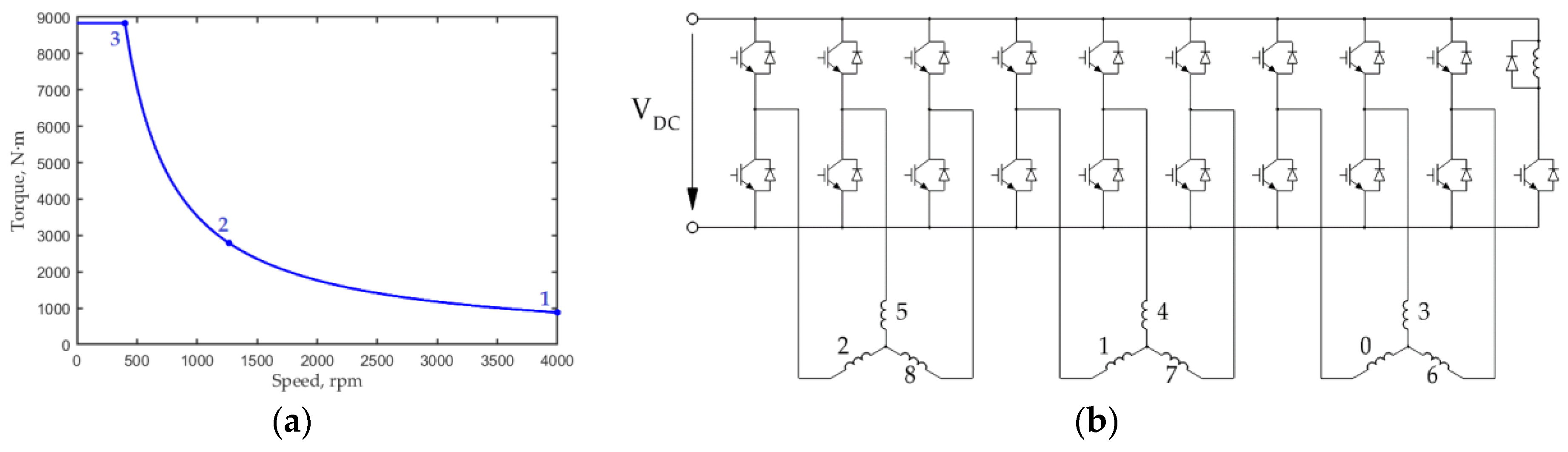
Figure 1. SHM design features: (a) general view of the SHM. The armature winding on the stator is not depicted so as not to obstruct; (b) SHM cross-section.
Mathematics 09 02859 g001
Figure 2. SHM diagrams: (a) traction characteristic of the motor; (b) inverter schematic; the numbers from 1 to 9 are the numbers of the phases of the SHM.
Mathematics 09 02859 g002
Figure 3. Geometric parameters of the SHM: (a) rotor radial dimensions; (b) stator and rotor axial and radial dimensions.
Mathematics 09 02859 g003
Figure 4. The motor cross-section and the magnitude plot of flux density; black outlines mark the extreme saturation level (>2 T): (a) before optimization; (b) after optimization; it can be observed that after optimization, the area of regions with flux density >2 T noticeably decreased.
Mathematics 09 02859 g004
Figure 5. Variations in the objectives during the optimization: (a) total losses <Plosses>; (b) maximum current amplitude in the armature winding; (c) maximum voltage amplitude in the armature winding; (d) objective function F.
Mathematics 09 02859 g005
Table 1. Operating points of the SHM taken into account in the optimization procedure.
Mode NumberTorque, N∙mRotational Speed, rpmMechanical Power, kW
18834000 370
227931265370
38833400370
Table 2. Some geometric parameters of the SHM that were not varied during the optimization.
ParameterValue [4]
Machine length without end winding parts L, mm545
Lengths of the stator stacks, Lstat1; Lstat2; Lstat3, mm101; 197; 101
The lengths of the rotor stacks, Lrot1; Lrot2; Lrot3, mm92; 184; 92
Axial clearance between excitation winding and rotor, Δa, mm30
Radial clearance between field winding and rotor Δr, mm27
Rotor yoke thickness R1-Rsleeve, mm22.8
Shaft radius Rshaft, mm70
Stator lamination height hlam, mm65
External radius of the stator housing Rhousing, mm367
Table 3. Parameters that were varied during the optimization.
ParameterInitial Value before the Optimization [4]
Housing thickness h, mm36
Total stator stacks length Lstator, mm399
Airgap width δ, mm2.3
Rotor slot factor frs1
Angles of field weakening at operating points 1,2,3, electrical radians0.61; 0.3; 0.25
Magnetic monopole densities at operating points 1,2,3, Wb/m0.48; 0.63; 1.2
Table 4. Winding parameters that were non-varied during the optimization.
ParameterSHM Prototype Described in [4]New Initial Design
Number of turns per stator armature layer57
Number of parallel strands per turn of the stator armature coil22
Dimensions of armature wire winding, mm2 3.15 × 4.52.5 × 4.5
The height of the stator slot part filled with the wire, mm36.441.1
Excitation winding resistance, Ohm10.216.8
Table 5. Comparison of the characteristics of the SHM prototype described in [4] and the characteristics of the new initial design used as the starting point for the optimization.
ValueSHM Prototype Described in [4]New Initial Design (before the Optimization)
Operating point123Brake mode123Brake mode
Speed, rpm400012654001100400012654001100
Current, A ampl197408886643142296669485
Mechanical power, kW370370370–540370370370–540
Active power, kW412387404–508412387405−509
Efficiency, %89.895.490.093.889.895.389.894.0
Total losses, kW41.918.041.032.242.218.142.132.4
Power factor0.990.820.91−0.650.990.810.88−0.62
Line voltage, V ampl9404721964621303661272642
Not symmetrized torque ripple, N∙m71.961.524.142.171.962.124.143.5
Symmetrized torque ripple, N∙m21.012.42.88.420.812.32.68.1
Excitation current, A5.68.126.310.75.58.124.810.8
Flux density in non-laminated parts of the magnetic core, T0.590.771.460.770.591.041.650.98
Table 6. Varied design parameters of the traction SHM after the optimization.
ParameterOptimal Design
Housing thickness h, mm32.8
Total stator stacks length Lstator, mm431
Airgap width δ, mm2.41
Rotor slot factor frs1.10
Angles of field weakening at operating points 1,2,3, electrical radians0.762; 0.400; 0.364
Magnetic monopole densities at operating points 1,2,3, Wb/m0.331; 0.678; 1.139
Table 7. Optimization results.
ValueNew Initial Design
(Before the Optimization)
After Optimization
Operating point123Brake mode123Brake mode
Speed, rpm400012654001100400012654001100
Current, A ampl142296669485176255601429
Mechanical power, kW370370370–540370370370–540
Mechanical losses, kW17.570.650.050.4517.570.650.050.45
Conductive winding losses, kW1.46.130.916.22.14.525.012.7
Eddy-current winding losses, kW5.22.51.14.36.02.11.03.8
Stator core losses, kW15.17.52.49.410.95.92.58.2
Rotor core losses, kW2.50.60.10.61.50.60.10.5
Excitation losses, kW0.40.87.51.40.51.511.92.0
Active power, kW412387405−509408384399−514
Efficiency, %89.895.389.894.090.596.190.194.9
Total losses (motor), kW42.218.142.132.438.715.240.527.6
Line voltage, V ampl1303661272642988632275621
Symmetrized torque ripple, N∙m20.812.32.68.118.912.53.09.4
Excitation current, A5.58.124.810.85.59.526.610.8
Flux density in non-laminated parts of the magnetic core, T0.590.771.460.770.480.981.650.91
Power factor0.990.810.88−0.620.970.960.96−0.74
Publisher’s Note: MDPI stays neutral with regard to jurisdictional claims in published maps and institutional affiliations.

