Article

Jet Impingement Cooling of a Rotating Hot Circular Cylinder with Hybrid Nanofluid under Multiple Magnetic Field Effects

1
Department of Mechanical Engineering, College of Engineering, University of Ha’il, Ha’il City 81451, Saudi Arabia
2
Department of Mechanical Engineering, Celal Bayar University, Manisa 45140, Turkey
3
Department of Physics, College of Science, Qassim University, Buraidah 51452, Saudi Arabia
4
Laboratory of Metrology and Energy Systems, National Engineering School of Monastir, University of Monastir, Monastir City 5000, Tunisia
5
Materials, Energy and Renewable Energies Research Unit, Faculty of Sciences, University of Gafsa, Gafsa 2112, Tunisia
6
Laboratory of Electro-Mechanical Systems (LASEM), National Engineering School of Sfax, University of Sfax, Sfax 3038, Tunisia
*
Author to whom correspondence should be addressed.
Mathematics 2021, 9(21), 2697; https://doi.org/10.3390/math9212697
Submission received: 24 September 2021 / Revised: 11 October 2021 / Accepted: 21 October 2021 / Published: 24 October 2021
(This article belongs to the Special Issue Modeling and Numerical Analysis of Energy and Environment 2021)

Abstract

:
The cooling performance of jet impinging hybrid nanofluid on a rotating hot circular cylinder was numerically assessed under the effects of multiple magnetic fields via finite element method. The numerical study was conducted for different values of Reynolds number ( 100 Re 300 ), rotational Reynolds number ( 0 Rew 800 ), lower and upper domain magnetic field strength ( 0 Ha 20 ), size of the rotating cylinder (2 w r 6 w) and distance between the jets (6 w ≤ H ≤ 16 w). In the presence of rotation at the highest speed, the Nu value was increased by about 5% when Re was increased from Re = 100 to Re = 300. This value was 48.5% for the configuration with the motionless cylinder. However, the rotations of the cylinder resulted in significant heat transfer enhancements in the absence or presence of magnetic field effects in the upper domain. At Ha1 = 0, the average Nu rose by about 175%, and the value was 249% at Ha1 = 20 when cases with the cylinder rotating at the highest speed were compared to the motionless cylinder case. When magnetic field strengths of the upper and lower domains are reduced, the average Nu decreases. The size of the cylinder is influential on the flow dynamics and heat transfer when the cylinder is rotating. An optimum value of the distance between the jets was obtained at H = 14 w, where the Nu value was highest for the rotating cylinder case. A modal analysis of the heat transfer dynamics was performed with the POD technique. As diverse applications of energy system technologies with impinging jets are available, considering the rotations of the cooled surface under the combined effects of using magnetic field and nanoparticle loading in heat transfer fluid is a novel contribution. The outcomes of the present work will be helpful in the initial design and optimization studies in applications from electronic cooling to convective drying, solar power and many other systems.

1. Introduction

Jet impinging heat transfer (j-imp HT) applications arise in different thermal engineering systems. Some examples include drying, solar power, electronic cooling, textiles and turbine blade cooling. In solar power applications, photovoltaic panel thermal management can be achieved by using impinging jets. Locally higher HT coefficients can be achieved. The coupled interactions among the established recirculations, pressure gradients and thermal field within the system make the system’s performance analysis very complex in the presence of complex geometries. Effects of different geometric factors and operating parameters on the j-imp HT characteristics were analyzed for single and multiple jets Garimella [1]. Many review works have been devoted to analyzing the convective HT with impinging jets: j-imp HT in the turbulent regime for a single circular j-imp [2], air j-imp HT in food processing [3] and j-imp in solar power [4].
The effectiveness of using liquid jets can be enhanced by introducing nano-sized particles in HT fluid, forming nanojets. In thermal energy systems, nanofluids (N-F) are widely used in different applications, such as solar, refrigeration and thermal management in diverse HT systems [5,6,7,8,9,10]. The potential benefits of using N-Fs in those systems have been shown. In j-imp HT, N-Fs have been used, and improved HT characteristics were reported in many studies [11,12,13,14,15]. In a review Mohammadpour and Lee [16], the effects of using N-Fs on the HT improvements for conventional and swirl type impinging jets were analyzed. Some challenges, such as nanoparticle agglomeration and pressure drop, were mentioned with future trends and applications. In the experimental work of Teamah et al. [17], an up to 62% increment in the HT coefficient was obtained with nanofluid as compared to water for j-imp on a flat surface. Using CuO nanoparticles delivered the best performance. Naphon and Wiriyasart [18] experimentally analyzed the nano j-imp HT in a micro channel heat sink by using TiO2 nanoparticles. They observed convective HT incrementation by about 18.56% at a nanofluid concentration of 0.015%, and no additional pressure drop was obtained. Some other aspects of j-imp HT with nanofluids have been considered, such as moving surface [19], flow pulsation [20,21], boiling HT [22,23] and surface corrugation [24,25]. The form of the target surface is also very important in j-imp HT [26,27]. Rotating objects have been considered in several convective HT applications. Size, rotational speed and the location of the object were found to be effective in altering the flow dynamics and HT characteristics [28,29,30]. Some studies considered the rotations of the surface with impinging jets [31,32,33,34].
The application of a magnetic field (MaF) in engineering is encountered in diverse applications, such as in geothermal energy, coolers of nuclear reactors, micro pumps, continuous casting processes and many others [35,36]. Finite element method (FEM) simulations of configurations with MaF effects have been proposed in diverse studies [37,38,39,40], and extensive literature on the electromagnetic forward problem computation via the FEM is available [41,42,43]. In convective HT, applications have also been considered with imposed external MaF for thermal management and flow control [44,45,46,47,48,49]. The effectiveness of using MaF was further elaborated by using nano-sized particles in HT fluid [50,51,52,53]. In j-imp HT, MaF effects were considered in several studies [54,55] and with nanojets [56,57]. In those studies, reduction in the convective HT was achieved, and adding nanoparticles improved the HT. The suppression of the vortices and potential of the HT entrancement can be achieved with MaF effects depending upon the geometry of the configuration, such as flow over step, or in cavity flows [58,59,60]. As different geometries and various corrugation levels of the impinging surfaces are available with impinging jets, there is potential for MaF to improve the convective HT.
The present study deals with the confined slot j-imp HT and flow features for a rotating surface located in between the domains that are under the effects of MaF of different strengthens. Two opposing cold jets were used for cooling the hot rotating cylinder, and MaFs in different domains were uniform and inclined. A hybrid nanofluid was used, as the HT fluid and the experimental data were available for the effective viscosity and thermal conductivity of the nanofluid. As there are many applications of impinging jets in different energy system technologies, the use of multiple MaF effects for a jet impinging on a hot rotating surface is a novel contribution. The MaF effects can be available within systems such as continuous casting systems for molten metals and nuclear reactor cooling, or they can be imposed as external sources for flow and HT control. The use of nanofluids in a jet configuration with accurate descriptions of nanofluid property relations improves the HT performance and gives more flexibility for convective HT control of the thermo-fluid system. In this study, modal analysis was used for exploring the heat transfer dynamics of the j-imp system under multiple MaF effects, and the details are explained in the following subsection of the manuscript.

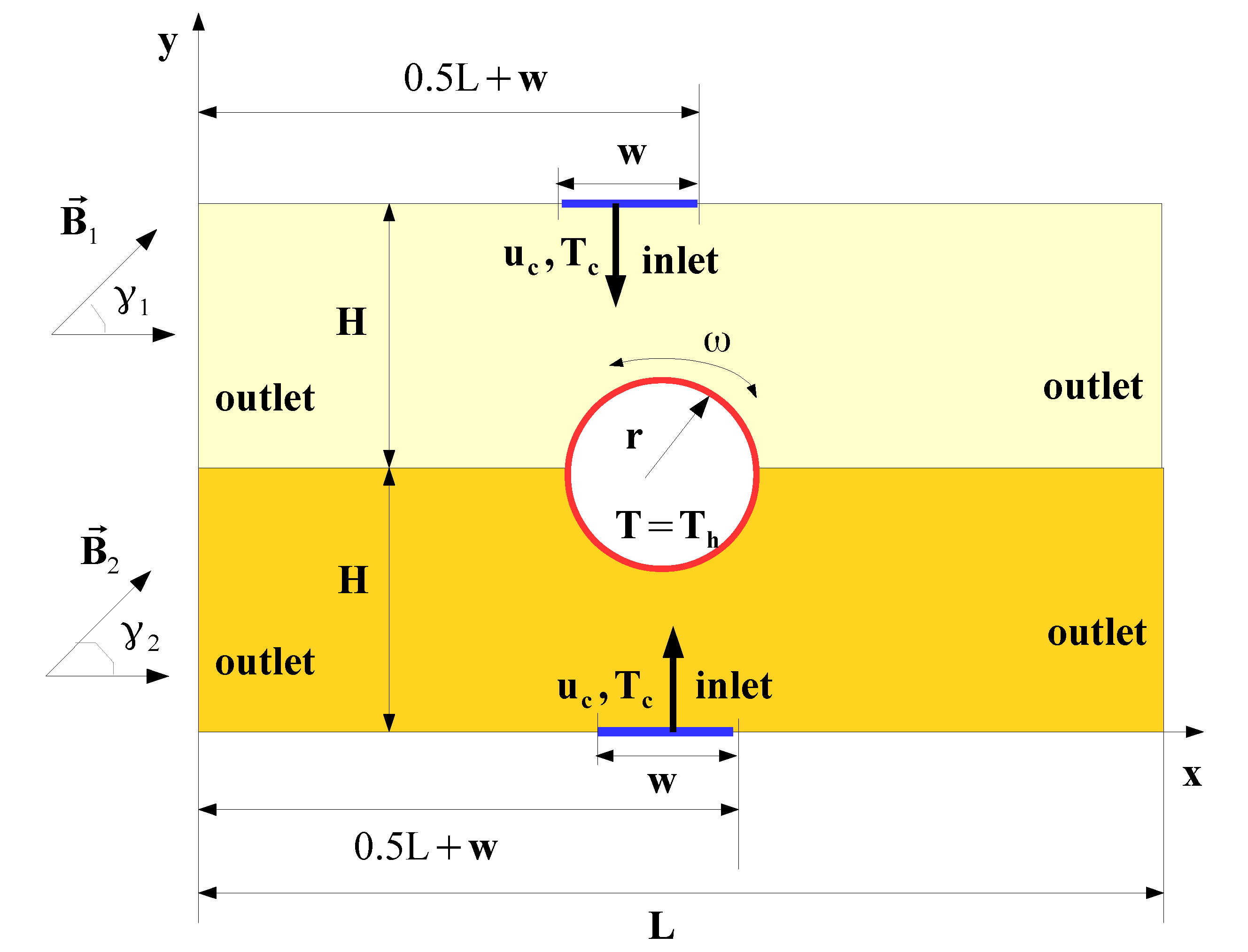
2. Mathematical Model

Jet impingement (j-imp) cooling performance with hybrid nanofluid (N-F) is explored for a rotating hot cylinder exposed to jets in opposite directions, as shown in Figure 1. A hot rotating cylinder (R-C) with radius r is used, with a rotational speed of ω . Single confined jets emerging from nozzles with width w are considered. The R-C is in the middle of the computational domain, and the upper and lower parts are exposed to uniform MaF with strengths of B 1 and B 2 . The inclinations of the MaF are denoted by γ 1 and γ 2 . The hot cylinder is maintained at a constant temperature of T h ; the cold fluid streams at temperature T c and velocity u c enter the domains. The distance of jet inlets to the interface is H, and the lengths of the upper and lower plates, which are adiabatic, is L.
As the HT fluid, hybrid N-F is used. It is 40% ethylene glycol and contains TiO 2 -Al 2 O 3 binary nanoparticles. Experimental data were used to derive viscosity ( μ n f ) and thermal conductivity ( k n f ) correlations for nanoparticle concentrations from 0.02 to 0.1% [61]. They are given by the following expressions [61]:
μ n f = 7.1074 + 3.65 ϕ 0.14097 T + 0.05176 ϕ T + 0.907 ϕ ϕ + 0.00092 T 2 ,
k n f = 0.386 e ( 2.27 ϕ + 0.002939 T ) .
They are valid for an 80:20 mixture ratio of TiO 2 -Al 2 O 3 in 40% EG. The valid temperature range is between 30 and 80 °C and concentration is between 0.02% and 0.1%. N-F behaves as Newtonian [61]. In the modeling with MaF, Joule heating, induced MaF effects and displacement currents are not considered. The viscous dissipation and natural convection effects are also ignored. The conservation equations are given as:
u x + v y = 0 ,
u u x + v u y = 1 ρ n f p x + ν n f 2 u x 2 + 2 u y 2 + σ n f B i 2 ρ n f v cos γ i sin γ i u sin 2 γ i ,
u v x + v v y = 1 ρ n f p y + ν n f 2 v x 2 + 2 v y 2 + σ n f B i 2 ρ n f u cos γ i sin γ i v cos 2 γ i ,
u T x + v T y = α n f 2 T x 2 + 2 T y 2 .
In the above representations, B i and γ i denote MaF strength and inclinations for upper i = 1 and lower i = 2 domains, respectively. Here, σ n f and α n f are the electrical conductivity and diffusivity of the nanofluid.
The boundary conditions in dimensional form are written as:
  • At the inlet,
    u = 0 , v = u c , T = T c .
  • At the exit:
    u x = 0 , v x = 0 , T x = 0
  • Top and bottom plate are adiabatic and stationary:
    u = v = 0 , T y = 0
  • On the rotating cylinder surface:
    u = ω ( y y c ) , v = ω ( x x c ) , T = T h
  • At the interface between the upper and lower domains:
    u 1 = u 2 , v 1 = v 2 , T n 1 = T n 2
At the exit of the channels, pressure outlet boundary conditions are utilized.
The following physical, non-dimensional parameters are relevant:
Re = ρ u c D h μ , Pr = ν α , Ha i = B i D h σ μ
where ρ ,   ν ,   α ,   μ and σ denote the density, kinematic viscosity, thermal diffusivity, dynamic viscosity and electrical conductivity of the nanofluid. The characteristic length based on the slot width is given by D h = 2 w.
As the solver, the Galerkin weighted residual FEM is used. In the formulation, residual R is obtained after using the approximated field variables in the equations. Different ordered Lagrange FEMs are utilized for approximations of field variable (F):
F = r = 1 N s Φ r s G k .
where Φ r is the shape function and G denotes the nodal value. The residual is forced to be zero in an average manner as:
V W R d V = 0 ,
where W represents the weight function, and R is the residual. Artificial diffusion with the streamline upwind Petrov–Galerkin method (SUPG) is used in the solver to handle local numerical instabilities. The biconjugate gradient stabilized iterative method solver (BICGStab) is used for fluid flow and heat transfer modules of code. The convergence criterion of 10 7 was assumed when converged solution results were achieved.
The cooling performance can be represented in terms of Nusselt number (Nu). Local and average Nu are given as:
Nu s = h s D h k n f = D h T h T c T s w , Nu m = 1 S 0 S Nu s d s .
where h s and S denote the local heat transfer coefficient and total length along the circumferential of the hot cylinder; D h is the hydraulic diameter.
Numerical simulations were checked for grid independency. Numerical tests were conducted for different grid sizes, and results are given in Figure 2a for the variations of the average Nu at two different MaF strengths of the upper domain. Grid system Gr4 with 115,534 elements was selected, and the distribution of the grid near the R-C is presented in Figure 2b.
The numerical code was validated by using different studies available in the literature. In the first study, numerical results from the work of Sahoo and Sharif [62] for j-imp cooling of a surface held at constant heat flux were used. Figure 3a presents the comparison results of average Nu for two different aspect ratios (AR) at Re = 500. The deviations are 0.6% and 1.3% from the reference solution at AR = 4 and AR = 10. Another validation was performed by using the confined slot j-imp cooling results available in [63,64]. Table 1 presents the stagnation point Nu at Re = 300. The highest deviation was 1.55%, from the results of [64]. Finally, the effect of using MF in convective HT was considered within a cavity by using the results of [65]. Comparison of average Nu for different MF strengths is shown in Figure 3b at Gr = 2 × 10 5 . The highest difference was found to be below 5% when the present solver results were compared. The results showed that the present code is capable of simulating the effects of MF in convective HT and j-imp HT.

3. Results and Discussion

Coupled interactions between the multiple MaF effects, rotational surface and forced convection of hybrid N-F on the cooling performance were examined for j-imp on a hot rotating cylinder. The upper and lower domains of the were exposed to uniform MaF of different strengths while double jets of hybrid N-F were used for different parts of the rotating cylinder. The nanoparticle concentration was taken as between 0.02 to 0.1%; the nanofluid behaved as a Newtonian fluid. The Reynolds number was between 100 and 300, and the unsteady flow effects were ignored. The MaF strengths and rotational Reynolds numbers were taken as 0 Ha 20 and 0 Rew 800 . Modal analysis was used for the heat transfer dynamics.

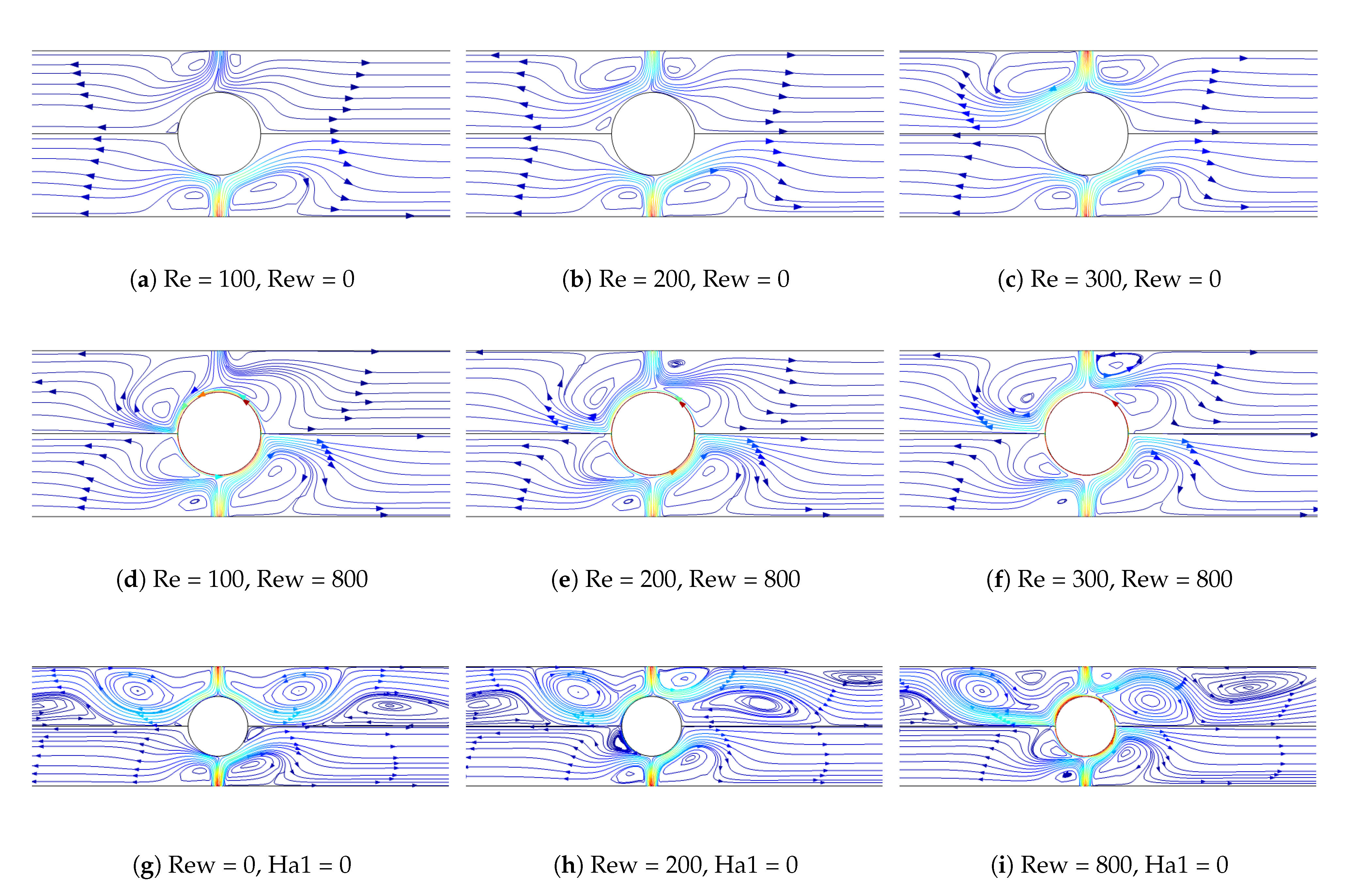
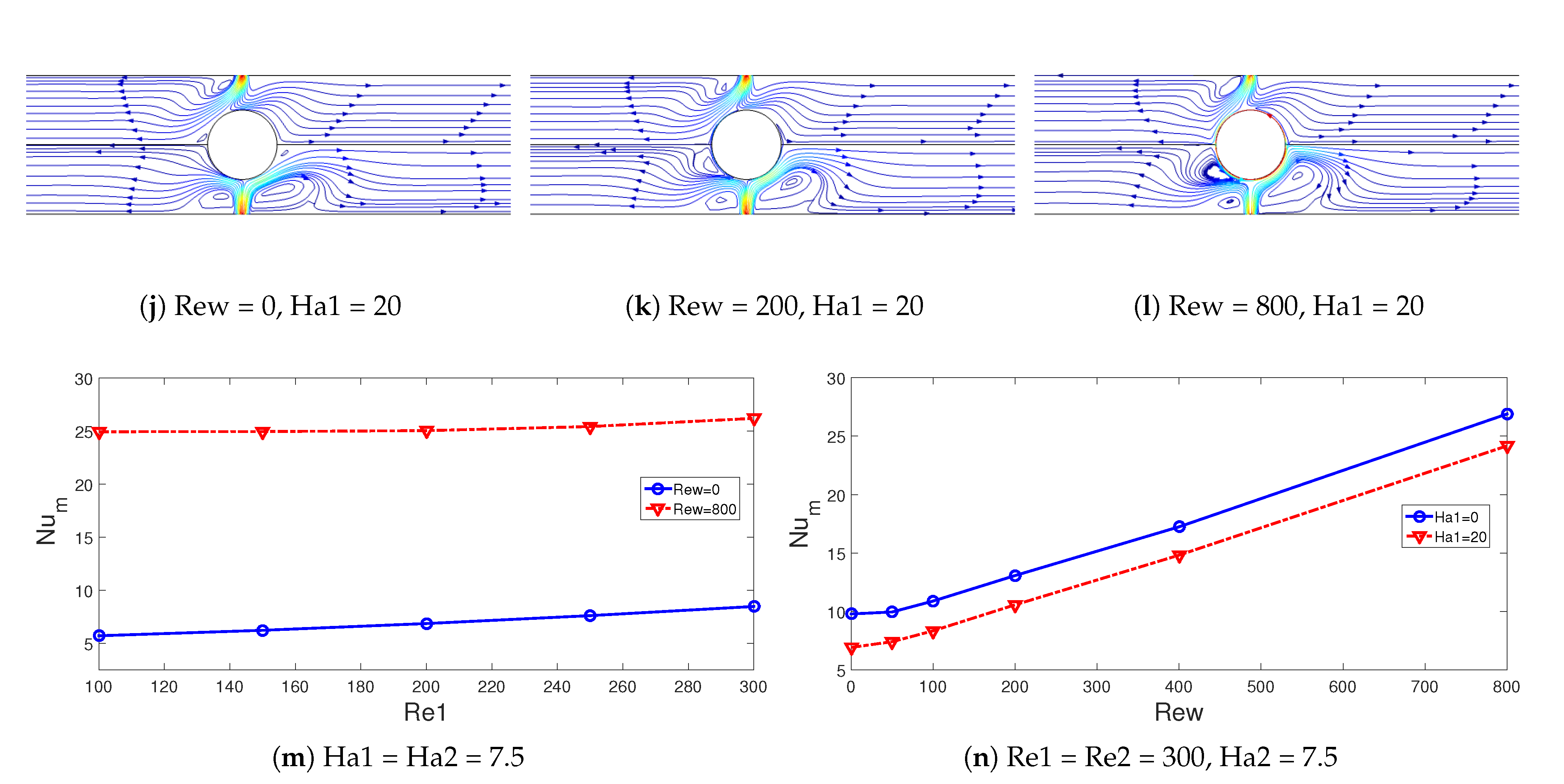
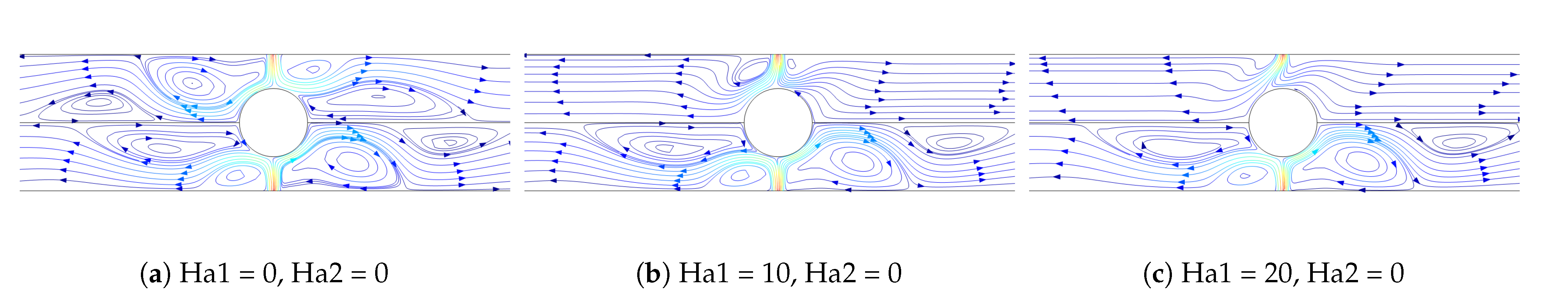
3.1. Computational Fluid Dynamics Simulation Results

Flow patterns are shown for different Re numbers in the absence (Figure 4a–c) and presence of (Figure 4d–f) rotational surface effects. When rotations were not active, due to confinement and entrainment, vortices were established near the inlet zones. As the Re was increased, vortex size enlarged. As the rotational surface effects were considered, the vortices near the inlet region were distorted due to the rotations of the cylinder, and additional recirculation zones were observed near the hot cylinder. Effects of Rew on the flow pattern distributions in the absence and presence of MaF in the upper domain are shown in Figure 4g–l. When there were no MaF effects present, recirculation zones near the inlet and and secondary vortices at the interface on the upper part were observed. When rotations were introduced, on the top wall of the upper domain, multi-recirculation regions were established. At Rew = 800, three vortices are shown adjacent to the upper domain top wall. As the MaF was imposed at the highest strength, suppression of the vortices in the upper region is shown for all Rew. Impacts of Re on the average Nu were weaker when rotational surface effects were considered at the highest speed, as shown in Figure 4m. For the case with a motionless cylinder, the average Nu rose by about 48.5%, but this amount was only 5% when rotational surface effects were dominant. The rotations of the cylinder brought significant enhancement of the average Nu as compared to the motionless cylinder configuration in the absence and presence of MaF effects. The enhancements were 175% and 249% when rotational effects at the highest speed were compared with the cases of stationary cylinder at Ha1 = 0 and Ha1 = 20, respectively (Figure 4n).
The suppression of the vortices within different domains by imposing MaF of various strengths is shown in Figure 5a–f for different (Ha1, Ha2) combinations. The computational domain is characterized by multiple recirculations near the inlet zones and interface boundaries when no MaF is present in the system. As is shown in Figure 5a–c, the upper zone recirculation regions were suppressed as Ha1 increased. The vortex size and its number can be adjusted by changing the MaF strengths of the upper and lower domains. The impacts of MaF on the average Nu variation are shown in Figure 5g for different combinations of upper and lower domain MaF strengths. The average Nu decreased with higher Ha1 or Ha2 values. As the MaF strength increased, the suppression of the vortices was observed within the domains, but the flow field was retarded and convective heat transfer was reduced. The trends in the average Nu-Ha1 curves are similar for different Ha2 values. When cases in the absence ((Ha1, Ha2) = (0, 0)) and presence of MaF effects at the highest strength ((Ha1, Ha2) = (20, 20)) are compared, reductions in average Nu by 54.5% are obtained. Reductions in the convective heat transfer with MaF have been shown in various studies for impinging jets. However, in this work, multiple domains were under the effects of MaF with different strengths for impinging jet cooling.
The size of the cylinder and distance between the opposite jets were expected to be influential on the convective heat transfer performance. The flow pattern variations for different sizes (H = 8 w) and different jet spacing (r = 4 w) are shown in Figure 6a–f and Figure 6g–l. For larger cylinder sizes, the distance between the inlet port and impinging surface was reduced; and the vortex size near the inlet regions was affected when rotational surface effects were considered. However, the effects on the flow patterns variations became significant at the largest cylinder size. The distance effects between the opposite jets on the flow patterns are shown in Figure 6 without rotations (g–i) and with rotational surface effects (j–l). At the highest distance, the recirculation regions near the inlet extended toward the cylinder while vortex size was increased. When rotations were considered, small vortices near the hot cylinder surface were established, while the impinging effects became weaker. For the flow dynamics and heat transfer, the size of the cylinder became influential when rotational surface effects were considered. The increment in the average Nu was 23.5% when varying the size from r = 2 w to r = 6 w at the highest rotational speed, and this value was only 1.5% without rotational effects (Figure 7a). The trends in the average Nu while varying the opposite jet distances were different up to H = 14 w, whether the rotations were active or not. As the rotations were present, the average Nu rose up to H = 14 w and then decreased from H = 14 w to H = 16 w (Figure 7b). This is attributed to the weakening of the impinging jet effects at the highest distance where flow field at the inlet zones was directed away from the hot surface of the cylinder. The optimum value of the distance between the jets was attained at H = 14 w, where the average Nu value achieved its highest value for the case with a rotating cylinder—the highest cylinder. In this case, the increment in the average Nu was obtained as 54.5% when jet spacing at the smallest value was compared. There was a 30% reduction in the average Nu when cases at H = 6 w and H = 14 w were compared in the absence of rotational surface effects.

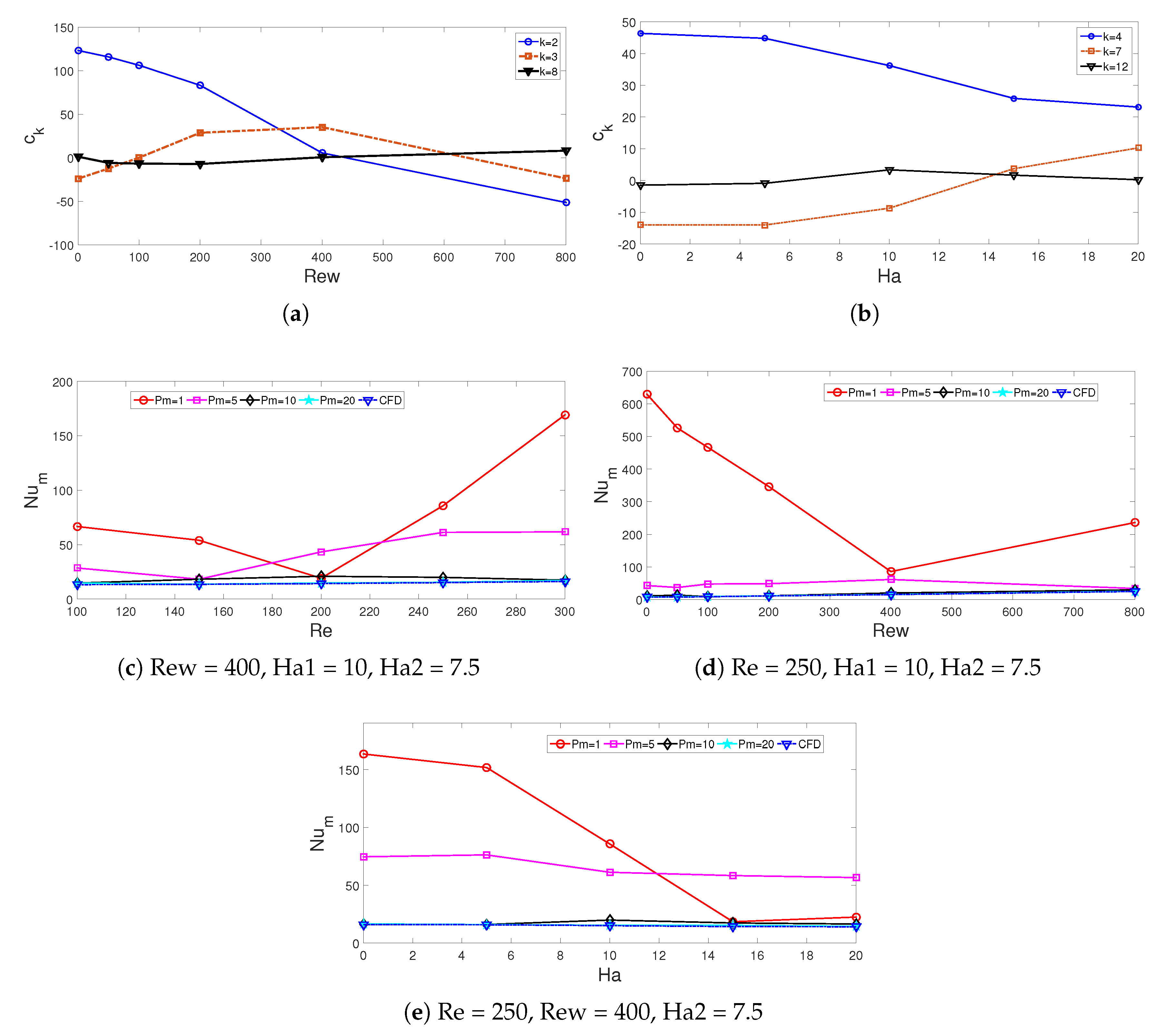
3.2. Modal Approach for Analyzing the Heat Transfer Dynamics

The cooling performance was represented with average Nu from the hot rotating cylinder. Local values of Nu along the circumferential of the cylinder were collected, and modal analysis was performed. The proper orthogonal decomposition (POD) technique was used. The method was used for flow control, identification of flow dynamics, model order reduction and the parametric estimation of various thermo-fluid system performance factors [66,67,68,69]. The dataset for the local Nu along the R-C was collected for different values of Re, Rew and Ha. They are stated in terms of modal representation with POD modes multiplied by coefficients as:
Nu = N u ¯ + k = 1 N c k ( Re , Rew , Ha ) Ψ ( x , y ) ,
where N is the number of modes and Ψ denotes the POD mode. Here, c k denotes the modal coefficient. The modes were obtained after solving the following integral eigenvalue problem:
V K ( x ) K ( x ) Ψ ( x ) d = Λ Ψ ( x ) ,
where the first term of the integral is the cross-correlation tensor, and Λ denotes the eigenvalues. Singular value decomposition may also be used to get the modes. The largest energy content was captured with the first mode, and it is distributed in a hierarchical manner. Mode coefficients can be obtained after the projection of the dataset onto modes due to the orthogonality features of the modes. The number of spatial points in the dataset is 1032. Parametric variations of Nu with different Re (eight values), Rew (eight values) and Ha (eight values) were considered. The number of snapshots was 8 × 8 × 8 = 512. The cumulative contribution (CC) of the modes was considered to determine the number of modes retained in the modal representation. For one, three and ten modes, the CC values were 0.681, 0.860 and 0.974, respectively. In the present work, a twenty mode approximation was considered where the CC value was 0.995. The modal coefficients are dependent upon the Re, Rew and Ha. The variations of several mode coefficients with varying Rew and Ha are presented in Figure 8a,b. The modal coefficients are sensitive to the variations in Rew and Ha. The reconstruction of the average Nu which denotes the cooling performance was achieved by superposing all of the modal coefficients multiplied by the corresponding modes. The modes were functions of spatial coordinates which were obtained with SVD. For any parameter of interest within the interval of Re, Rew and Ha, interpolation among the modal coefficients could be utilized to determine the cooling performance at the specified parameter. Polynomials, splines and neural network-based approximations for the modal coefficients can be considered. Variations in the average Nu from the R-C with different numbers of modes are presented in Figure 8c–e. Table 2 presents the comparison results for the average Nu variations with different parametric combinations of (Re, Ha, Rew) considering different numbers of modes. A 20-mode approximation of the Nu gave satisfactory results and captured the variations in Re, Rew and Ha as compared to CFD.

4. Conclusions

In the current study, convective HT performance for impinging jets onto a rotating hot circular cylinder was numerically assessed under multiple MaF effects. Binary nanoparticles were used in the HT fluid, and different strengths of MaF were considered in the opposing jet domains. The following conclusions were drawn from the numerical simulation results:
  • The coupled interactions between the rotating hot body, forced flow of hybrid nanofluid and multiple magnetic field effects determine the flow recirculations with the systems and heat transfer enhancement amounts.
  • When the rotational surface effects are dominant, the impacts of Re on the average Nu increase become weak as compared to motionless cylinder case. When the lowest and highest Re cases were compared, a 5% rise of average Nu was seen at Rew = 800, and it was 48.5% at Rew = 0.
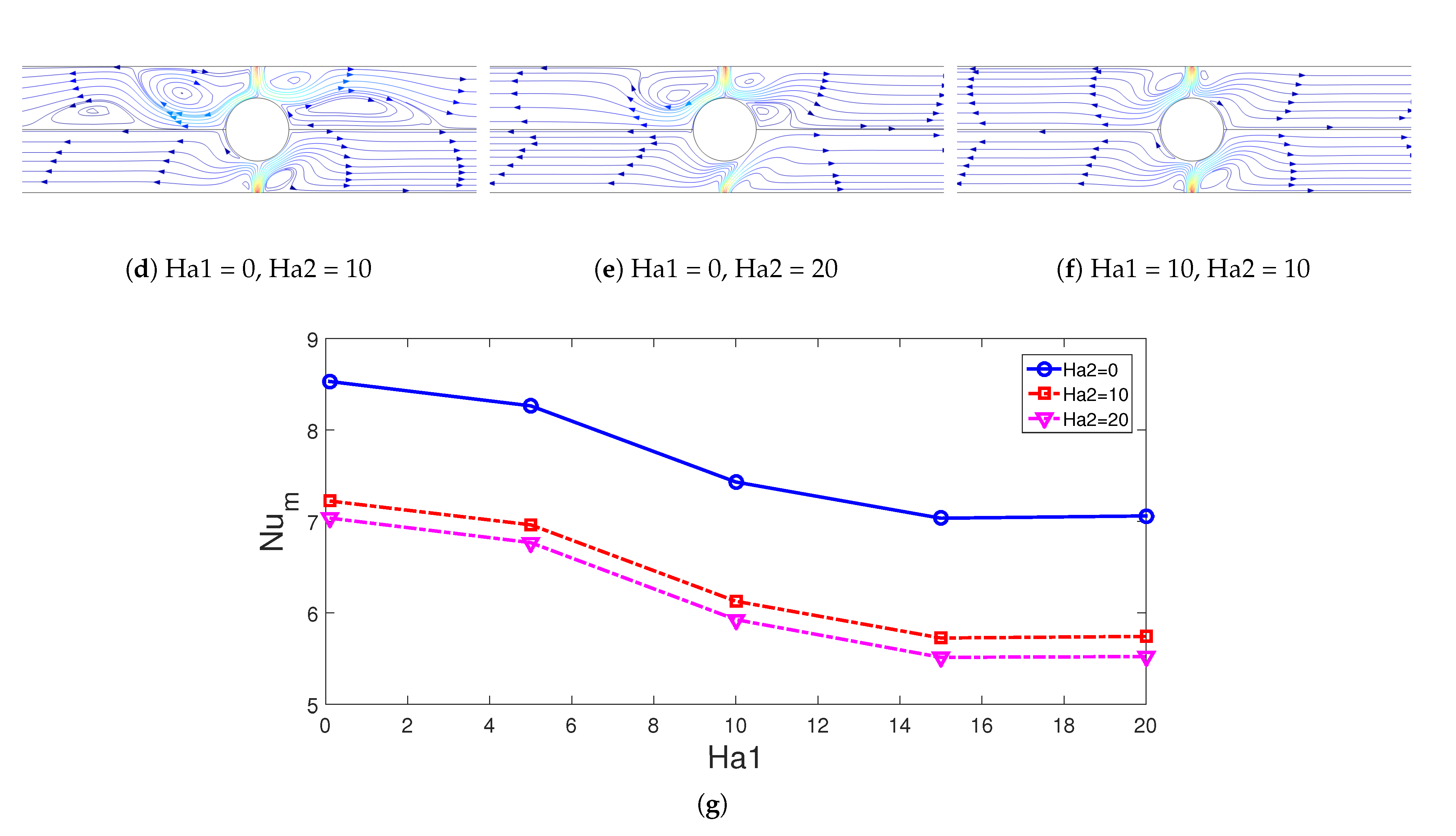
  • Impacts of rotation on the HT enhancement are significant when MaF effects are present in the system. The average Nu rose by about 249% at Ha1 = 0, and it was only 175% at Ha1 = 0.
  • When the configuration in the presence of MaF effects at the highest strength is compared with the case in the absence of MaF in both domains, a 54.5% reduction in the average Nu was obtained.
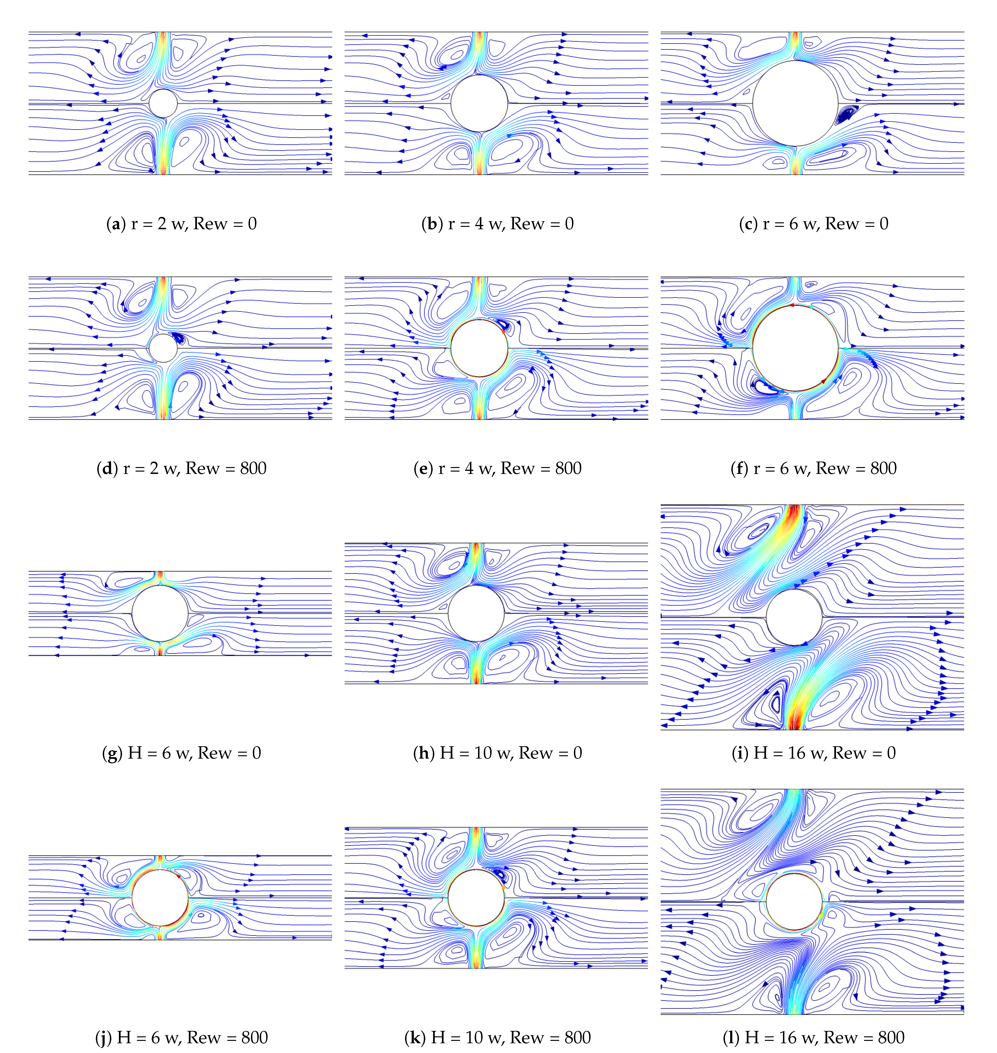
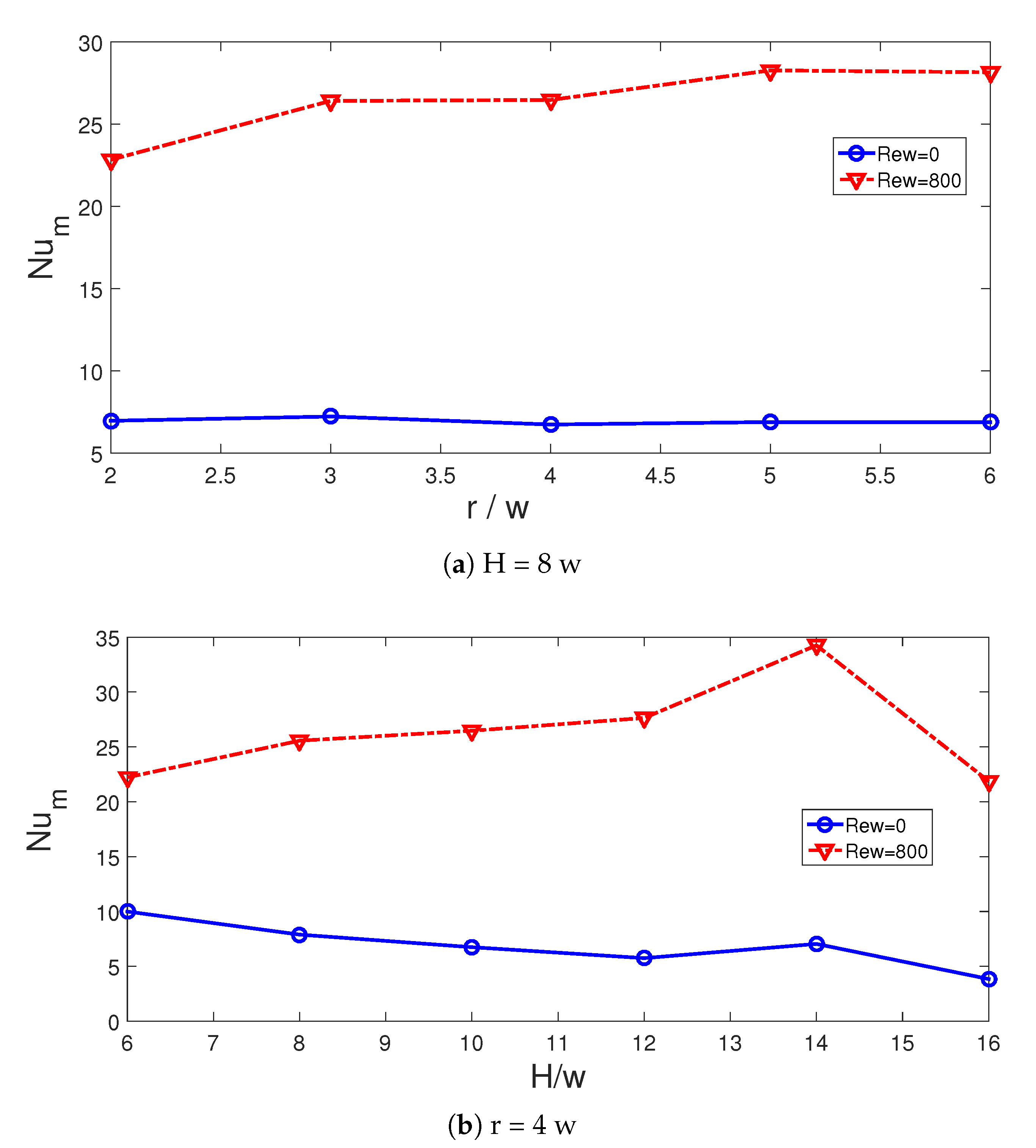
  • When cases with the smallest and highest cylinder sizes were compared at the highest rotational speeds, the increment in the average Nu was observed as 23.5%.
  • The optimum value of distance between the opposing jets was obtained at H = 14 w for the maximum HT, where a 54.5% rise in the average Nu was attained as compared to the case at the smallest spacing.
  • A modal analysis of the local Nu was proposed with 20-modes, with varying Re, Rew and Ha parameters.
The present work may be extended to include unsteady flow effects, different thermal boundary conditions, multiple rotating cylinder configurations, non-uniform magnetic field effects and different nanoparticle types. A multi-domain POD approach may also be utilized where different numbers of modes for the lower and upper domains may be considered. Efficient interpolation methods may also be used among the modal coefficients which are dependent upon the parameters to predict the cooling performance of the system. These will increase the applicability of the present configuration to diverse energy system technologies.

Author Contributions

Conceptualization, F.S.; methodology, F.S., L.K. and B.A.; software, F.S.; validation, L.K.; formal analysis, F.S., F.A. and L.K.; investigation, F.S., L.K. and B.A.; writing—original draft preparation, F.S.; writing—review and editing, F.S., B.A., L.K., W.A. and L.B.S.; visualization, F.S. and L.K.; supervision, F.S., B.A., L.K., W.A. and L.B.S. All authors have read and agreed to the published version of the manuscript.

Funding

This research has been funded by Scientific Research Deanship at University of Ha’il - Saudi Arabia through project number RG-21 057.

Institutional Review Board Statement

Not applicable.

Informed Consent Statement

Not applicable.

Conflicts of Interest

The authors declare no conflict of interest.

Abbreviations

Bmagnetic field strength
CCcumulative contribution
c k mode coefficient
D h hydraulic diameter
hlocal heat transfer coefficient
Hdistance between the jet and interface
HaHartmann number
kthermal conductivity
Lplate length
nsurface normal
NuNusselt number
ppressure
Pmmode number
PrPrandtl number
Rewrotational Reynolds number
ReReynolds number
rcylinder radius
Ttemperature
u, vx-y velocity components
Wweight function
x, yCartesian coordinates
x c , y c cylinder center
Greek Characters
α thermal diffusivity
ϕ solid volume fraction
ν kinematic viscosity
θ non-dimensional temperature
ρ density of the fluid
γ inclination angle
Subscripts
ccold
hhot
maverage
nfnanofluid
psolid particle

References

  1. Garimella, S.V. Heat transfer and flow fields in confined jet impingement. Annu. Rev. Heat Transf. 2000, 11, 413–494. [Google Scholar] [CrossRef]
  2. Jambunathan, K.; Lai, E.; Moss, M.; Button, B. A review of heat transfer data for single circular jet impingement. Int. J. Heat Fluid Flow 1992, 13, 106–115. [Google Scholar] [CrossRef]
  3. Sarkar, A.; Nitin, N.; Karwe, M.; Singh, R.P. Fluid flow and heat transfer in air jet impingement in food processing. J. Food Sci. 2004, 69, CRH113–CRH122. [Google Scholar] [CrossRef]
  4. Nadda, R.; Kumar, A.; Maithani, R. Efficiency improvement of solar photovoltaic/solar air collectors by using impingement jets: A review. Renew. Sustain. Energy Rev. 2018, 93, 331–353. [Google Scholar] [CrossRef]
  5. Sajid, M.U.; Ali, H.M. Recent advances in application of nanofluids in heat transfer devices: A critical review. Renew. Sustain. Energy Rev. 2019, 103, 556–592. [Google Scholar] [CrossRef]
  6. Pordanjani, A.H.; Aghakhani, S.; Afrand, M.; Mahmoudi, B.; Mahian, O.; Wongwises, S. An updated review on application of nanofluids in heat exchangers for saving energy. Energy Convers. Manag. 2019, 198, 111886. [Google Scholar] [CrossRef]
  7. Khanafer, K.; Vafai, K. A review on the applications of nanofluids in solar energy field. Renew. Energy 2018, 123, 398–406. [Google Scholar] [CrossRef]
  8. Aly, A.M.; Mohamed, E.M.; Alsedais, N. The magnetic field on a nanofluid flow within a finned cavity containing solid particles. Case Stud. Therm. Eng. 2021, 25, 100945. [Google Scholar] [CrossRef]
  9. Kakaç, S.; Pramuanjaroenkij, A. Single-phase and two-phase treatments of convective heat transfer enhancement with nanofluids–A state-of-the-art review. Int. J. Therm. Sci. 2016, 100, 75–97. [Google Scholar] [CrossRef]
  10. Ahmed, F. Experimental investigation of Al2O3-water nanofluid as a secondary fluid in a refrigeration system. Case Stud. Therm. Eng. 2021, 101024. [Google Scholar] [CrossRef]
  11. Kareem, Z.S.; Balla, H.H.; AbdulWahid, A.F. Heat transfer enhancement in single circular impingement jet by CuO-water nanofluid. Case Stud. Therm. Eng. 2019, 15, 100508. [Google Scholar] [CrossRef]
  12. Manca, O.; Mesolella, P.; Nardini, S.; Ricci, D. Numerical study of a confined slot impinging jet with nanofluids. Nanoscale Res. Lett. 2011, 6, 1–16. [Google Scholar] [CrossRef] [Green Version]
  13. Barewar, S.D.; Tawri, S.; Chougule, S.S. Heat transfer characteristics of free nanofluid impinging jet on flat surface with different jet to plate distance: An experimental investigation. Chem. Eng. Process.-Process. Intensif. 2019, 136, 1–10. [Google Scholar] [CrossRef]
  14. Lamraoui, H.; Mansouri, K.; Saci, R. Numerical investigation on fluid dynamic and thermal behavior of a non-Newtonian Al2O3–water nanofluid flow in a confined impinging slot jet. J. Non-Newton. Fluid Mech. 2019, 265, 11–27. [Google Scholar] [CrossRef]
  15. Balla, H.H.; Hashem, A.L.; Kareem, Z.S.; Abdulwahid, A.F. Heat transfer potentials of ZnO/water nanofluid in free impingement jet. Case Stud. Therm. Eng. 2021, 27, 101143. [Google Scholar] [CrossRef]
  16. Mohammadpour, J.; Lee, A. Investigation of nanoparticle effects on jet impingement heat transfer: A review. J. Mol. Liq. 2020, 316, 113819. [Google Scholar] [CrossRef]
  17. Teamah, M.A.; Dawood, M.M.K.; Shehata, A. Numerical and experimental investigation of flow structure and behavior of nanofluids flow impingement on horizontal flat plate. Exp. Therm. Fluid Sci. 2016, 74, 235–246. [Google Scholar] [CrossRef]
  18. Naphon, P.; Wiriyasart, S. Pulsating flow and magnetic field effects on the convective heat transfer of TiO2-water nanofluids in helically corrugated tube. Int. J. Heat Mass Transf. 2018, 125, 1054–1060. [Google Scholar] [CrossRef]
  19. Buonomo, B.; Manca, O.; Bondareva, N.S.; Sheremet, M.A. Thermal and fluid dynamic behaviors of confined slot jets impinging on an isothermal moving surface with nanofluids. Energies 2019, 12, 2074. [Google Scholar] [CrossRef] [Green Version]
  20. Selimefendigil, F.; Öztop, H.F. Numerical study and identification of cooling of heated blocks in pulsating channel flow with a rotating cylinder. Int. J. Therm. Sci. 2014, 79, 132–145. [Google Scholar] [CrossRef]
  21. Akdag, U.; Akcay, S.; Demiral, D. Heat transfer enhancement with laminar pulsating nanofluid flow in a wavy channel. Int. Commun. Heat Mass Transf. 2014, 59, 17–23. [Google Scholar] [CrossRef]
  22. Mitra, S.; Saha, S.K.; Chakraborty, S.; Das, S. Study on boiling heat transfer of water–TiO2 and water–MWCNT nanofluids based laminar jet impingement on heated steel surface. Appl. Therm. Eng. 2012, 37, 353–359. [Google Scholar] [CrossRef]
  23. Liu, Z.H.; Qiu, Y.H. Boiling heat transfer characteristics of nanofluids jet impingement on a plate surface. Heat Mass Transf. 2007, 43, 699–706. [Google Scholar] [CrossRef]
  24. Li, P.; Guo, D.; Liu, R. Mechanism analysis of heat transfer and flow structure of periodic pulsating nanofluids slot-jet impingement with different waveforms. Appl. Therm. Eng. 2019, 152, 937–945. [Google Scholar] [CrossRef]
  25. Mahdavi, M.; Sharifpur, M.; Meyer, J.P. Fluid flow and heat transfer analysis of nanofluid jet cooling on a hot surface with various roughness. Int. Commun. Heat Mass Transf. 2020, 118, 104842. [Google Scholar] [CrossRef]
  26. Singh, T.P.; Kumar, A.; Satapathy, A.K. Role of a Sinusoidal Wavy Surface in Enhancement of Heat Transfer Using Turbulent Dual Jet. J. Heat Transf. 2021, 143, 032002. [Google Scholar] [CrossRef]
  27. Selimefendigil, F.; Öztop, H.F. Forced convection and thermal predictions of pulsating nanofluid flow over a backward facing step with a corrugated bottom wall. Int. J. Heat Mass Transf. 2017, 110, 231–247. [Google Scholar] [CrossRef]
  28. Roslan, R.; Saleh, H.; Hashim, I. Effect of rotating cylinder on heat transfer in a square enclosure filled with nanofluids. Int. J. Heat Mass Transf. 2012, 55, 7247–7256. [Google Scholar] [CrossRef]
  29. Khanafer, K.; Aithal, S.M.; Vafai, K. Mixed convection heat transfer in a differentially heated cavity with two rotating cylinders. Int. J. Therm. Sci. 2019, 135, 117–132. [Google Scholar] [CrossRef]
  30. Selimefendigil, F.; Oztop, H.F. Analysis and predictive modeling of nanofluid-jet impingement cooling of an isothermal surface under the influence of a rotating cylinder. Int. J. Heat Mass Transf. 2018, 121, 233–245. [Google Scholar]
  31. Benim, A.C.; Ozkan, K.; Cagan, M.; Gunes, D. Computational investigation of turbulent jet impinging onto rotating disk. Int. J. Numer. Methods Heat Fluid Flow 2007, 17, 284–301. [Google Scholar] [CrossRef]
  32. Jeng, T.M.; Tzeng, S.C.; Xu, R. Heat transfer characteristics of a rotating cylinder with a lateral air impinging jet. Int. J. Heat Mass Transf. 2014, 70, 235–249. [Google Scholar] [CrossRef]
  33. Scheichl, B.; Kluwick, A. Laminar spread of a circular liquid jet impinging axially on a rotating disc. J. Fluid Mech. 2019, 864, 449–489. [Google Scholar] [CrossRef] [Green Version]
  34. Chen, Y.M.; Wang, K.C. Experimental study on the forced convective flow in a channel with heated blocks in tandem. Exp. Therm. Fluid Sci. 1998, 16, 286–298. [Google Scholar] [CrossRef]
  35. Kabeel, A.; El-Said, E.M.; Dafea, S. A review of magnetic field effects on flow and heat transfer in liquids: Present status and future potential for studies and applications. Renew. Sustain. Energy Rev. 2015, 45, 830–837. [Google Scholar] [CrossRef]
  36. Sheikholeslami, M.; Rokni, H.B. Magnetohydrodynamic CuO–water nanofluid in a porous complex-shaped enclosure. J. Therm. Sci. Eng. Appl. 2017, 9, 041007. [Google Scholar] [CrossRef]
  37. Nesliturk, A.I.; Tezer-Sezgin, M. The finite element method for MHD flow at high Hartmann numbers. Comput. Methods Appl. Mech. Eng. 2005, 194, 1201–1224. [Google Scholar] [CrossRef] [Green Version]
  38. Nguyen, T.T.; Bouillault, F.; Daniel, L.; Mininger, X. Finite element modeling of magnetic field sensors based on nonlinear magnetoelectric effect. J. Appl. Phys. 2011, 109, 084904. [Google Scholar] [CrossRef] [Green Version]
  39. Lee, S.H.; Kim, Y.S. Finite element analysis for cooling effect of magnetic fluid with alternating magnetic field. J. Appl. Phys. 2009, 105, 07B510. [Google Scholar] [CrossRef]
  40. Selimefendigil, F.; Öztop, H.F. Corrugated conductive partition effects on MHD free convection of CNT-water nanofluid in a cavity. Int. J. Heat Mass Transf. 2019, 129, 265–277. [Google Scholar] [CrossRef]
  41. Ansari, S.; Farquharson, C.G. 3D finite-element forward modeling of electromagnetic data using vector and scalar potentials and unstructured grids. Geophysics 2014, 79, E149–E165. [Google Scholar] [CrossRef]
  42. Yin, W.; Lu, M.; Yin, L.; Zhao, Q.; Meng, X.; Zhang, Z.; Peyton, A. Acceleration of eddy current computation for scanning probes. Insight-Non-Destr. Test. Cond. Monit. 2018, 60, 547–555. [Google Scholar] [CrossRef]
  43. Huang, R.; Lu, M.; Peyton, A.; Yin, W. A novel perturbed matrix inversion based method for the acceleration of finite element analysis in crack-scanning eddy current NDT. IEEE Access 2020, 8, 12438–12444. [Google Scholar] [CrossRef]
  44. Kumar, M.A.; Reddy, Y.D.; Rao, V.S.; Goud, B.S. Thermal radiation impact on MHD heat transfer natural convective nano fluid flow over an impulsively started vertical plate. Case Stud. Therm. Eng. 2021, 24, 100826. [Google Scholar] [CrossRef]
  45. Ghasemi, B.; Aminossadati, S.; Raisi, A. Magnetic field effect on natural convection in a nanofluid-filled square enclosure. Int. J. Therm. Sci. 2011, 50, 1748–1756. [Google Scholar] [CrossRef]
  46. Waqas, H.; Farooq, U.; Naseem, R.; Hussain, S.; Alghamdi, M. Impact of MHD radiative flow of hybrid nanofluid over a rotating disk. Case Stud. Therm. Eng. 2021, 26, 101015. [Google Scholar] [CrossRef]
  47. Sheremet, M.A.; Oztop, H.; Pop, I.; Al-Salem, K. MHD free convection in a wavy open porous tall cavity filled with nanofluids under an effect of corner heater. Int. J. Heat Mass Transf. 2016, 103, 955–964. [Google Scholar] [CrossRef]
  48. Ma, Y.; Mohebbi, R.; Rashidi, M.M.; Yang, Z. MHD convective heat transfer of Ag-MgO/water hybrid nanofluid in a channel with active heaters and coolers. Int. J. Heat Mass Transf. 2019, 137, 714–726. [Google Scholar] [CrossRef]
  49. Khalid, A.; Khan, I.; Khan, A.; Shafie, S.; Tlili, I. Case study of MHD blood flow in a porous medium with CNTS and thermal analysis. Case Stud. Therm. Eng. 2018, 12, 374–380. [Google Scholar] [CrossRef]
  50. Kolsi, L.; Alrashed, A.A.A.A.; Al-Salem, K.; Oztop, H.F.; Borjini, M.N. Control of natural convection via inclined plate of CNT-water nanofluid in an open sided cubical enclosure under magnetic field. Int. J. Heat Mass Transf. 2017, 111, 1007–1018. [Google Scholar] [CrossRef]
  51. Naphon, P.; Wiriyasart, S. Pulsating TiO2/water nanofluids flow and heat transfer in the spirally coiled tubes with different magnetic field directions. Int. J. Heat Mass Transf. 2017, 115, 537–543. [Google Scholar] [CrossRef]
  52. Sheikholeslami, M.; Mahian, O. Enhancement of PCM solidification using inorganic nanoparticles and an external magnetic field with application in energy storage systems. J. Clean. Prod. 2019, 215, 963–977. [Google Scholar] [CrossRef]
  53. Aidaoui, L.; Lasbet, Y.; Selimefendigil, F. Improvement of transfer phenomena rates in open chaotic flow of nanofluid under the effect of magnetic field: Application of a combined method. Int. J. Mech. Sci. 2020, 179, 105649. [Google Scholar] [CrossRef]
  54. Lee, H.; Ha, M.; Yoon, H. A numerical study on the fluid flow and heat transfer in the confined jet flow in the presence of magnetic field. Int. J. Heat Mass Transf. 2005, 48, 5297–5309. [Google Scholar] [CrossRef]
  55. Nishiyama, H.; Kuzuhara, M.; Solonenko, O.; Kamiyama, S. Numerical modeling of an impinging and compressible dusted plasma jet controlled by a magnetic field. Plasma Chem. Plasma Process. 1999, 19, 363–381. [Google Scholar] [CrossRef]
  56. Selimefendigil, F.; Öztop, H.F. Al2O3-water nanofluid jet impingement cooling with magnetic field. Heat Transf. Eng. 2020, 41, 50–64. [Google Scholar] [CrossRef]
  57. Nimmagadda, R.; Haustein, H.D.; Asirvatham, L.G.; Wongwises, S. Effect of uniform/non-uniform magnetic field and jet impingement on the hydrodynamic and heat transfer performance of nanofluids. J. Magn. Magn. Mater. 2019, 479, 268–281. [Google Scholar] [CrossRef]
  58. Abbassi, H.; Nassrallah, S.B. MHD flow and heat transfer in a backward-facing step. Int. Commun. Heat Mass Transf. 2007, 34, 231–237. [Google Scholar] [CrossRef]
  59. Hussain, S.; Ahmed, S.E. Unsteady MHD forced convection over a backward facing step including a rotating cylinder utilizing Fe3O4-water ferrofluid. J. Magn. Magn. Mater. 2019, 484, 356–366. [Google Scholar] [CrossRef]
  60. Selimefendigil, F.; Öztop, H.F. Hydro-thermal performance of CNT nanofluid in double backward facing step with rotating tube bundle under magnetic field. Int. J. Mech. Sci. 2020, 185, 105876. [Google Scholar] [CrossRef]
  61. Urmi, W.; Rahman, M.; Hamzah, W. An experimental investigation on the thermophysical properties of 40% ethylene glycol based TiO2-Al2O3 hybrid nanofluids. Int. Commun. Heat Mass Transf. 2020, 116, 104663. [Google Scholar] [CrossRef]
  62. Sahoo, D.; Sharif, M. Numerical modeling of slot-jet impingement cooling of a constant heat flux surface confined by a parallel wall. Int. J. Therm. Sci. 2004, 43, 877–887. [Google Scholar] [CrossRef]
  63. Chou, Y.; Hung, Y. Impingement cooling of an isothermally heated surface with a confined slot jet. ASME Trans. J. Heat Transf. 1994, 116, 479–482. [Google Scholar] [CrossRef]
  64. Manca, O.; Ricci, D.; Nardini, S.; Di Lorenzo, G. Thermal and fluid dynamic behaviors of confined laminar impinging slot jets with nanofluids. Int. Commun. Heat Mass Transf. 2016, 70, 15–26. [Google Scholar] [CrossRef]
  65. Zhang, T.; Che, D. Double MRT thermal lattice Boltzmann simulation for MHD natural convection of nanofluids in an inclined cavity with four square heat sources. Int. J. Heat Mass Transf. 2016, 94, 87–100. [Google Scholar] [CrossRef]
  66. Berkooz, G.; Lumley, P.H.J.L. The proper orthogonal decomposition in the analysis of turbulent flows. Annu. Rev. Fluid Mech. 1993, 25, 539–575. [Google Scholar] [CrossRef]
  67. Sirisup, S.; Karniadakis, G.E. Stability and accuracy of periodic flow solutions obtained by a POD-penalty method. J. Phys. D 2005, 202, 218–237. [Google Scholar] [CrossRef]
  68. Hasan, N.; Sanghi, S. Proper orthogonal decomposition and low-dimensional modelling of thermally driven two-dimensional flow in a horizontal rotating flow. J. Fluid Mech. 2007, 573, 265–295. [Google Scholar] [CrossRef]
  69. Selimefendigil, F.; Polifke, W. Nonlinear, proper-orthogonal-decomposition-based model of forced convection heat transfer in pulsating flow. AIAA J. 2014, 52, 131–145. [Google Scholar] [CrossRef]
Figure 1. Model description with boundary conditions.
Mathematics 09 02697 g001
Figure 2. Grid independence test results: Average Nu variations for different grid sizes at two MaF strengths of the upper domain (a) and grid distribution (b) (Re1 = Re2 = 200, Rew = 100, Ha2 = 10, H = 8 w, r = 4 w).
Mathematics 09 02697 g002
Figure 3. The average Nu comparison for slot j-im cooling at two values of aspect ratio (AR) where the surface is kept at an isothermal hot temperature (reference values of [62] were used) (a) and comparisons of average Nu for convective HT with varying MaF strengths (reference values of [65] were used) (b).
Mathematics 09 02697 g003
Figure 4. Effects of Re on the streamline variations under the motionless (ac) and rotating (df) cylinder impacts (Ha1 = 7.5, Ha2 = 7.5, H = 8 w, r = 4 w). Effects of Rew on the streamline variations in the absence (gi) and presence (jl) of upper domain MaF (Re1 = 300, Re2 = 300, Ha2 = 7.5, H = 8 w, r = 4 w); average Nu variations with changes in Re1 (m) and Rew (n) (H = 8 w, r = 4 w).
Mathematics 09 02697 g004aMathematics 09 02697 g004b
Figure 5. Impacts of MaF strength of the domains (Ha1, Ha2) on the distribution of streamlines (af) and average Nu variations (g) (Re1 = Re2 = 200, Rew = 100, H = 8 w, r = 4 w).
Mathematics 09 02697 g005aMathematics 09 02697 g005b
Figure 6. Effects of the hot cylinder size on the streamline distributions for the cases without (ac) and with (df) rotational surface (Re1 = Re2 = 300, Ha1 = 10, Ha2 = 7.5, H = 8 w); impacts of distance from the jets to interface boundary on the streamline variations in the absence (gi) and presence (jl) of rotations (Re1 = Re2 = 300, Ha1 = 10, Ha2 = 7.5, r = 4 w).
Mathematics 09 02697 g006
Figure 7. Average Nu variations with changes in size of the cylinder (a) and distance from the jets to interface boundary (b) (Re1 = Re2 = 300, Ha1 = 10, Ha2 = 7.5).
Mathematics 09 02697 g007
Figure 8. Modal coefficients’ variations with changes in Rew (a), Ha (b) and approximation of average Nu from the hot cylinder with different numbers of modes and variations with respect to changes in Re (c), Rew (d) and Ha (e).
Mathematics 09 02697 g008
Table 1. Stagnation Nu comparisons for confined slot j-imp at Re = 300.
Reference StudyRe = 300
Present study9.81
Ref. [63]9.85
Ref. [64]9.66
Table 2. Comparisons of modal approximations of average Nu from the hot rotating cylinder with varying Re, Ha and Rew considering different numbers of modes.
ReHaRewNm (CFD)Nm (Pm = 20)Nm (Pm = 10)Nm (Pm = 5)Nm (Pm = 1)
100.0000006.24976.44629.563257.3214545.8495
100.0000050.00006.82377.121311.918417.3907462.4441
100.00000400.000014.688414.974118.631528.152780.9423
100.00000800.000024.543425.512831.327879.0200200.1170
100.000010.000005.64705.93617.169949.7720493.4111
100.000010.0000100.00006.87066.963210.27707.4057308.0403
100.000010.0000200.00008.83388.85708.942744.0794179.6151
100.000010.0000800.000023.990824.132529.106583.9645259.1009
100.000020.000005.46735.59385.992954.9489477.0083
100.000020.000050.00006.07266.25767.039112.4069391.0110
100.000020.0000100.00006.88756.93758.231915.3442308.9107
100.000020.0000200.00008.74758.89608.781949.1804167.7980
100.000020.0000400.000012.645712.928217.901922.0853122.6875
100.000020.0000800.000021.604721.955432.678965.2207469.4697
200.0000007.83877.996710.697174.6170687.7526
200.0000050.00008.22688.472011.95209.6814591.5352
200.00000100.00009.13109.261612.139429.0391511.3187
200.00000200.000011.064211.302211.224730.8318359.0287
200.00000800.000026.666926.689430.375930.581546.3589
200.000010.000006.56696.88249.793144.4367576.1642
200.000010.0000200.000010.086410.296110.633329.5709272.8990
200.000010.0000400.000014.207814.363020.931643.291819.1135
200.000010.0000800.000024.127224.346430.245650.9392265.3572
200.000020.000006.21076.48867.403751.6364544.8552
200.000020.000050.00006.75836.91246.87847.2988453.0497
200.000020.0000100.00007.65837.71018.738018.4243374.5025
200.000020.0000800.000022.681122.229828.670032.9669409.4980
300.0000009.78969.825115.783381.4567862.7452
300.0000050.00009.959910.07215.335818.1471755.0554
300.00000100.000010.895711.161714.190851.4394675.1634
300.00000200.000013.077213.229118.319583.1912545.4293
300.00000400.000017.243917.530918.841471.4711263.1526
300.00000800.000026.891927.133027.401966.571950.5082
300.000010.000007.89047.929911.734738.9112694.0833
300.000010.000050.00008.16428.2603216.672148.1251584.9435
300.000010.0000100.00009.27699.4359510.689061.3910526.4681
300.000010.0000200.000011.784811.994914.806377.0788427.1771
300.000010.0000400.000016.165816.199717.389461.7393169.3253
300.000010.0000800.000025.561425.869229.022573.8450180.4926
300.000020.000006.92726.99628.629744.9572609.7692
300.000020.000050.00007.41847.52297.893120.1793514.5291
300.000020.0000100.00008.35018.48978.841337.1866438.6225
300.000020.0000200.000010.574310.861813.344746.6147313.8373
300.000020.0000400.000014.821414.9855316.235766.144057.5720
300.000020.0000800.000024.167624.355130.147881.6907308.1989
Publisher’s Note: MDPI stays neutral with regard to jurisdictional claims in published maps and institutional affiliations.

