1. Introduction
With the development of automation in the manufacturing and production industries, increasing types of automation equipment have been designed to replace human labor and improve performance [
1]. Automation equipment can be used for many purposes such as spray-painting [
2], laser-cutting [
3], welding [
4], polishing [
5], and the handling of objects [
6].
Pitipong et al. [
7] used two cameras to investigate screw tightening. The two cameras were placed equal distances from the screw and photographed from different perspectives. Image processing was then used to measure the angle of the screw and detect whether the screw was perpendicular to the screw hole. However, the accuracy of the coordinate position of the screw hole was not considered. The screw used by Pitipong et al. [
7] was much larger than the one used in our research. In our research, two cameras are placed at different distances from the screw hole; one camera photographs the screw hole from afar, while the other does so from a close distance. The screw used is an M1.4 screw, which is much smaller than that used in [
7]. Image processing is used in our research to detect the accurate position of the screw hole.
This study designed a human–machine interface (HMI) for controlling the manipulator that tightens an M1.4 screw. An electric screwdriver is modified and installed on the end of a manipulator. One charge-coupled device (CCD) camera is fixed on the stationary frame above the screw holes to detect their positions. Another CCD camera is installed on the end effect of the manipulator. Once the screw has been positioned above the chosen screw hole, the second camera photographs the screw hole to fine-tune the position of the manipulator.
The visual system [
8,
9] and HMI were designed using Microsoft Visual Studio C++ (Microsoft Co., Redmond, WA, USA). By clicking the buttons on the interface, different commands can be performed such as image processing, selecting the screw hole, starting the manipulator, and starting the electric screwdriver.
The center coordinates of a screw hole, calculated using image processing, are transformed into the objective coordinates of the manipulator through coordinate transformation. Once the screw has arrived at a fixed height above the intended screw hole, the camera installed on the end effect of the manipulator photographs the screw hole. The system then processes the image, detects the position of the screw hole, and transforms it into the coordinate system of the manipulator to fine-tune the manipulator, increasing the positioning control.
Finally, when the screw is in the appropriate position, touching the screw hole, the user clicks the button to start the motor in the screwdriver, finishing the process of screw tightening.
2. Image Processing
After the camera photographs screw holes on the workpiece, the picture must be processed to detect the center coordinates of the screw holes. Images are processed using OpenCV, which involves the following processing methods: minimum circumcircle, binarization [
10], edge detection [
11], grayscale [
12], center of gravity [
13], bilateral filter [
14], and Gaussian filter [
15].
3. Coordinate Transformation
The coordinates of the screw hole, determined using image processing, must be transformed into the coordinate system of the manipulator through coordinate transformation.
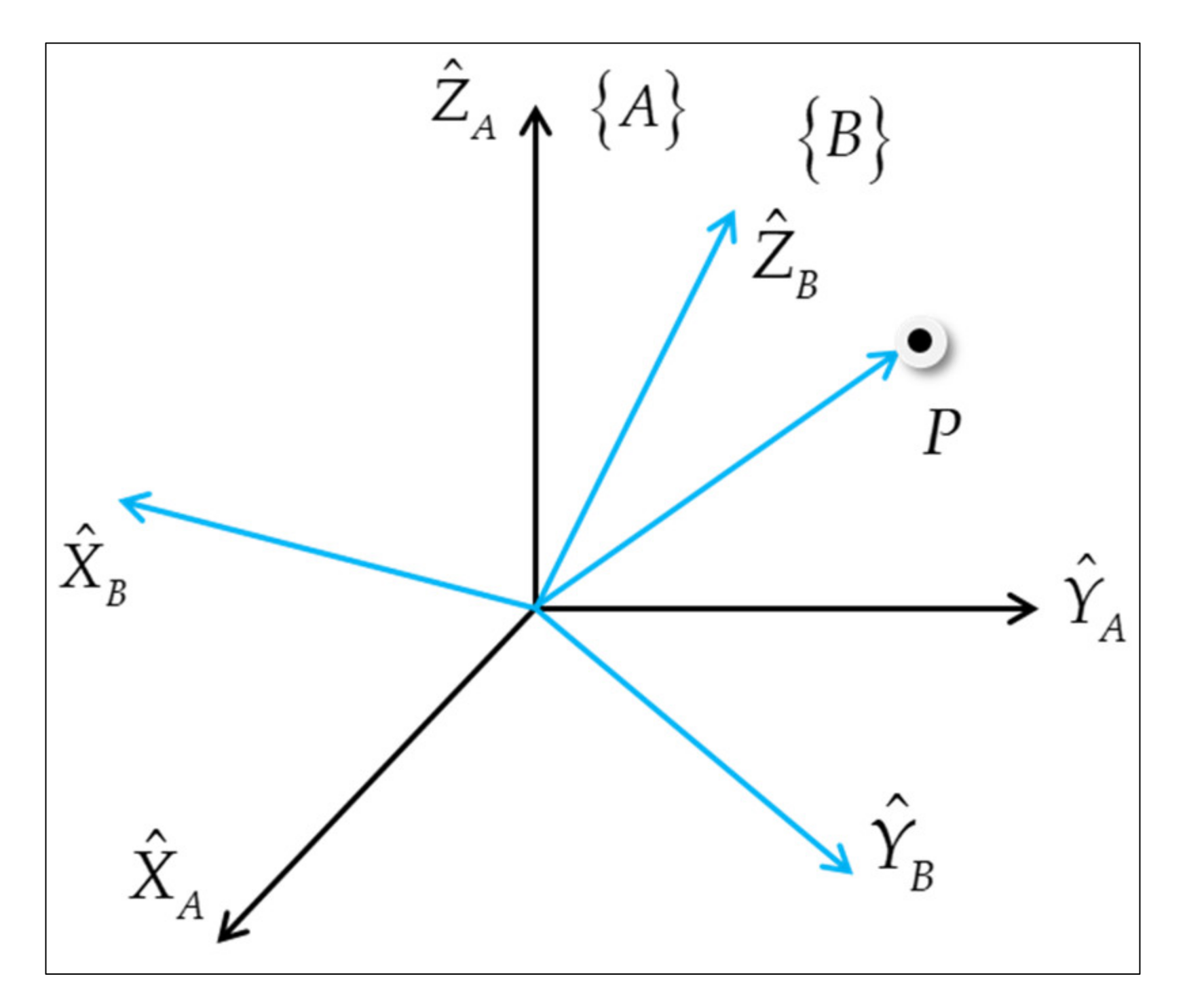
Consider a point
P and two coordinate systems {
A} and {
B}, as shown in
Figure 1. Accordingly,
AP represents the point
P described in coordinate system {
A},
BP represents the point
P described in coordinate system {
B}, and
represents the unit vector of the X-direction of {
A}.
[
] denotes the three unit vectors of {
B} described in the coordinate system {
A}. The rotation matrix between {
A} and {
B} is composed of an inner product of these unit vectors:
The prime of the matrix denotes the transpose matrix. The equation representing the transformation between
AP and
BP is as follows,
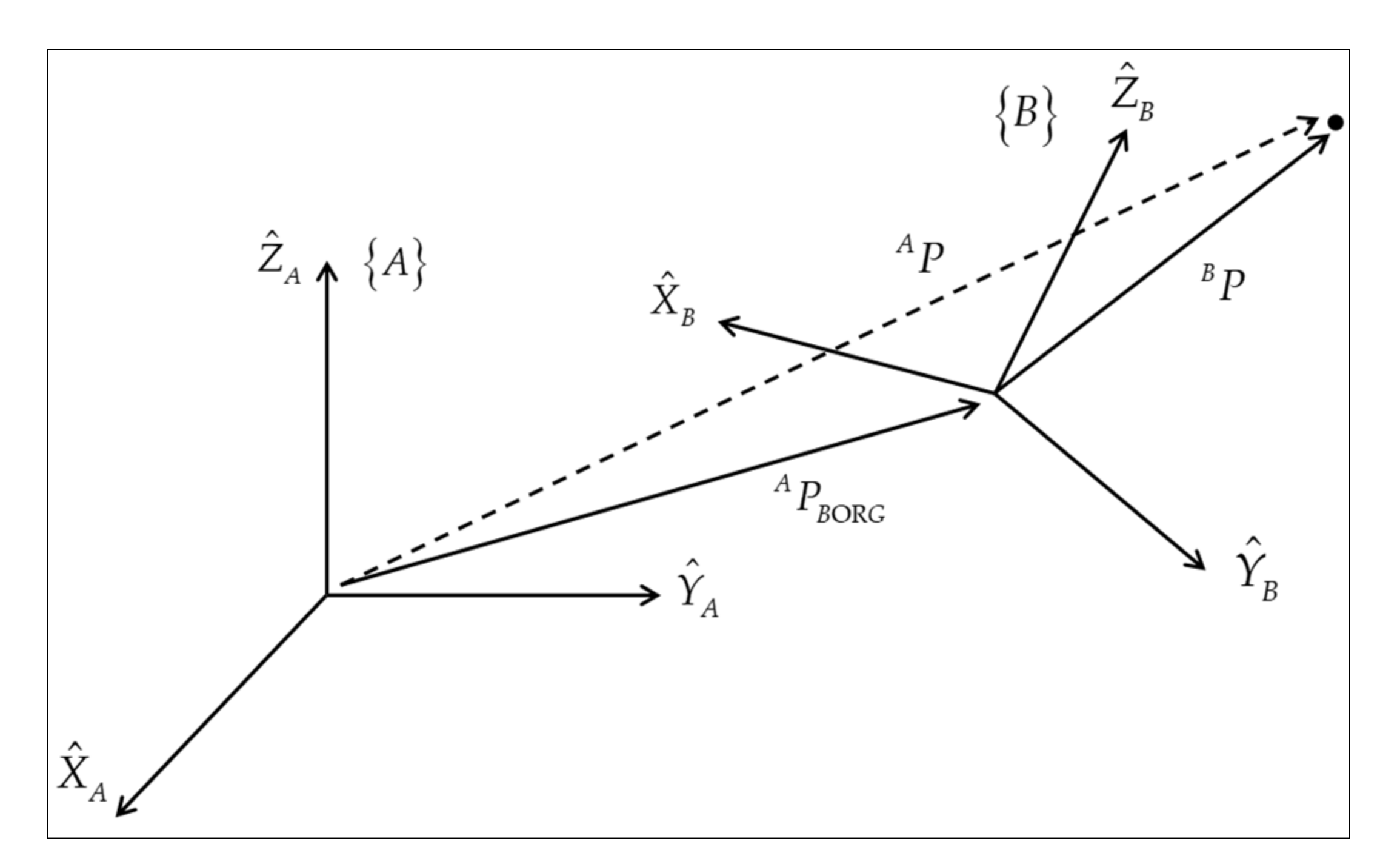
The displacement between the origins of {
A} and {
B} is denoted by
APBORG, as shown in
Figure 2. The equation representing the transformation between
AP and
BP is then as follows,
where
APCORG denotes the translation vector from the origin of the Camera 1 coordinate system to the origin of the manipulator coordinate system, i.e., (
) and
denotes the rotation matrix between the two coordinate systems, consisting of
r11~
r33.
A 4 × 4 transformation matrix can be used to describe the transformation of
P,
4. Experiment Platform and Equipment
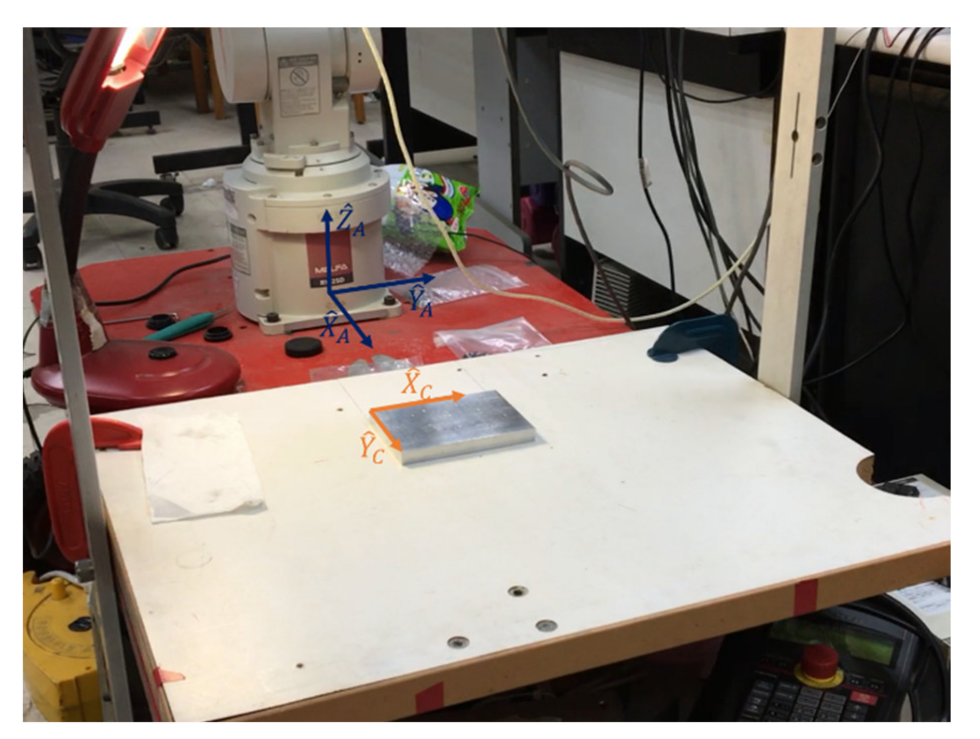
As shown in
Figure 3, a manipulator with six degrees of freedom and Camera 1 are fixed on the stationary frame of the platform; thus, the position of the manipulator relative to that of Camera 1 does not change. Camera 1 is fixed above the screw holes of the workpiece. Camera 2 is installed on the end effect of the manipulator and photographs the screw hole. The resolution of Camera 1 and 2 is 1280 × 960 and 1024 × 768, respectively. The focal length and aperture of the lenses are fixed during the experiment. An Arduino UNO microcontroller board is used to control a dc motor in the electric screwdriver located on the manipulator and an L298N motor controller is used to drive the motor to tighten the screw. The actual diameter of the M1.4 screw hole is 1.1 mm. Thus, the system has to identify a 1.1 mm hole using image processing. Some fixing mechanisms were designed to fix the cameras.
Table 1 summarizes the equipment used in this study.
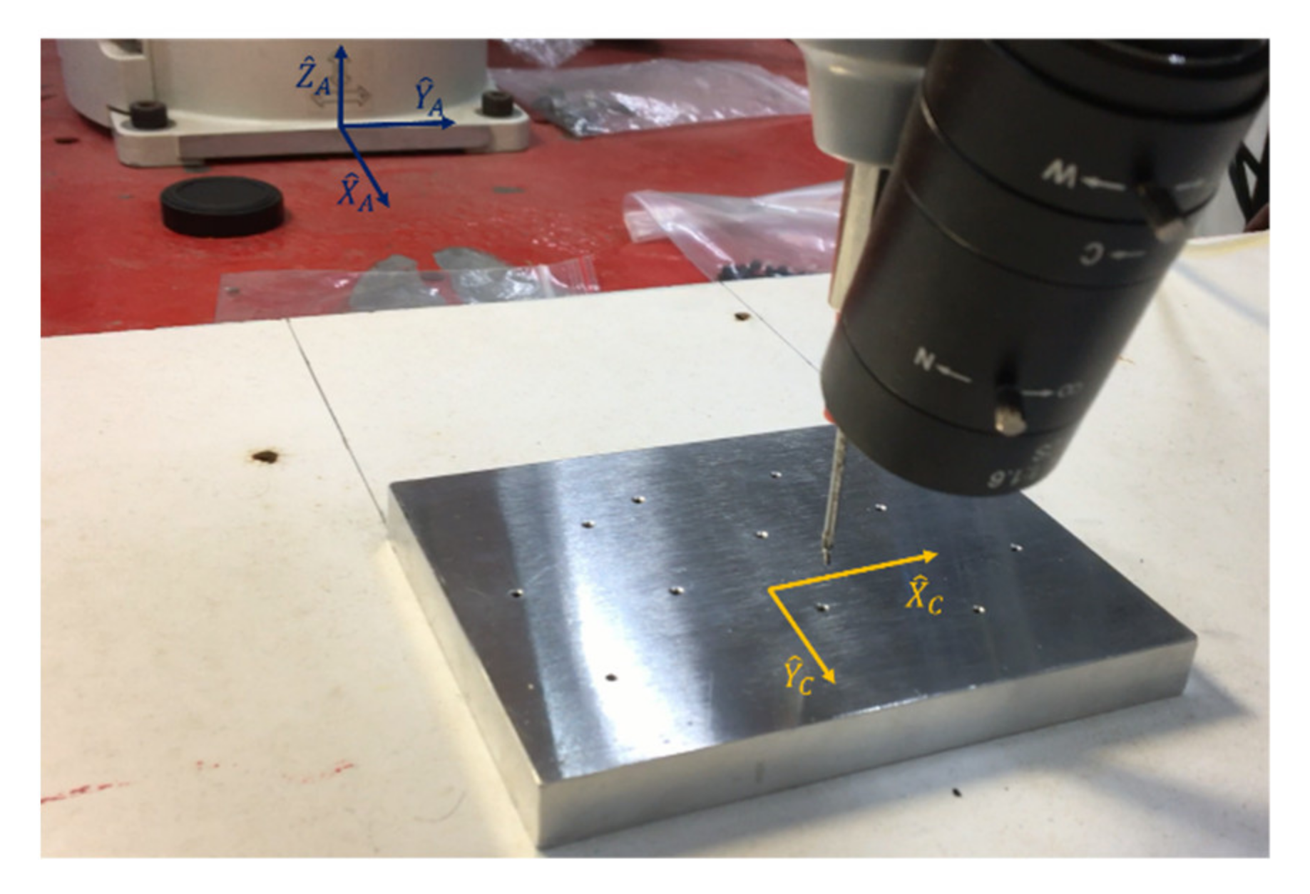
5. Transformation between Camera 1 and Manipulator
The coordinates of the screw hole, calculated using image processing, must be transformed into the coordinate system of the manipulator through coordinate transformation. Therefore, the equation representing the transformation between Camera 1 and the manipulator is required. The coordinate systems of the manipulator and Camera 1 are defined as {
A} and {
C}, respectively, as shown in
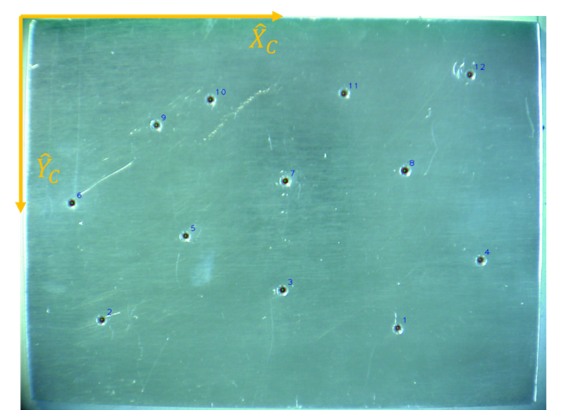
Figure 4. The origin of {
A} is at the center of the robot’s base, and the unit of measurement used in the coordinate system is millimeters. The origin of {
C} is defined at the upper left corner of an image taken by Camera 1 (
Figure 5). One length unit in the X-direction multiplied by one length unit in the
Y-direction equals one pixel.
5.1. Transformation Formula
where
APCORG denotes the translation vector from the origin of the Camera 1 coordinate system to the origin of the manipulator coordinate system, i.e., (
).
A 4 × 4 matrix is used as the transformation matrix, with 12 unknown elements required by calculation. The objective
ZA is set as 253 and
ZC is set at 0; thus, the formula can be simplified to the following equation with six unknown elements,
5.2. Measurement Data
At least six () and () data points are required to solve Equation (8) for the six unknowns. In the present experiment, the manipulator was manually controlled and the screw was aligned above the screw holes vertically to determine the () data. Each screw hole was aligned three times and the average coordinates were determined. For the same screw hole, if the error was larger than 0.1 mm, the datum was deleted and measurement was repeated. The parameter 0.1 is a custom value for the range of error. Tightening the M1.4 screw with that parameter is allowed. Image processing was used to solve for ().
It should be noted that increasing the number of measurement data can increase the accuracy of the least square approach. However, greater accuracy is not required for the calibration of Camera 1 since fine tuning will be performed for Camera 2. If it is necessary to speed up the experimental process, the least square method can be omitted to reduce the number of screw hole detections by half. Furthermore, due to the fact that the elements
r11~
r22 of the rotation matrix
only depend on angle, there are only three unknowns in Equation (8). The calibration of Camera 1 can be performed with just about 3 points measured on the workpiece.
Table 2 lists the measurement data of twelve screw holes.
5.3. Calculation
The 12 data points in
Table 2 are substituted into Equation (8) as follows,
The equations are simplified as follows,
Here,
C is the matrix of the {
C} data and
AX and
AY are the matrices of the {
A} data. Using the 12 data points, the six unknowns are calculated using the least square method,
Next, the value of the transformation matrix
T can be obtained,
Due to the influence of the preset z axis, the elements of the third row of the matrix is not symmetrical as in Equation (1). However, r12 is not equal to r21, which is due to the existence of measurement errors of data () and (). By using an automatic process, (firstly, randomly move the screw hole workpiece) the coordinates of the screw hole can be determined using image processing. These coordinates can then be substituted into Equation (8) and automatically transformed into coordinates in the manipulator’s coordinate system.
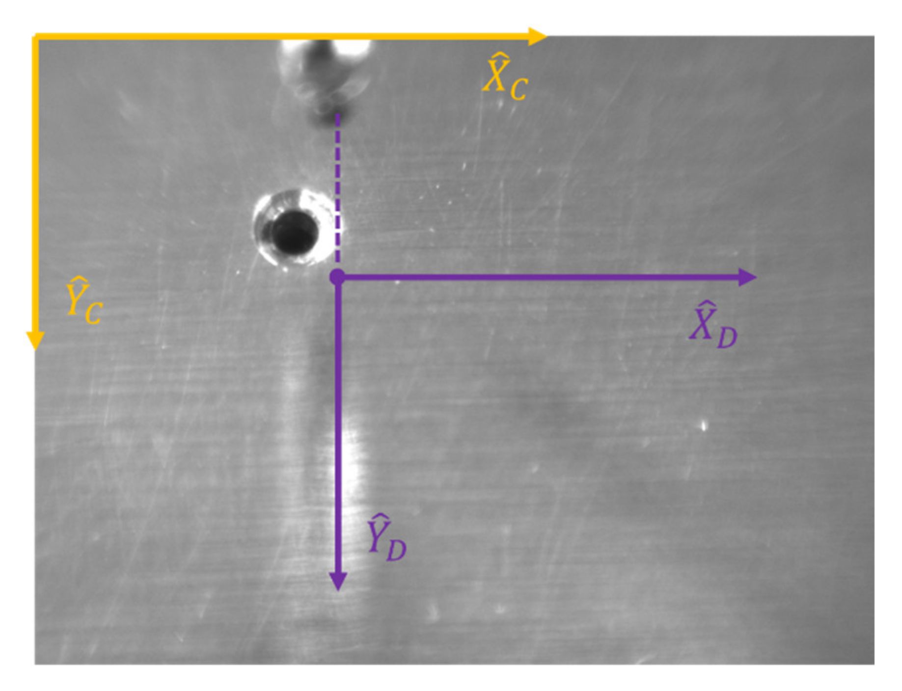
6. Transformation Equation between Camera 2 and Manipulator
Camera 2 photographs the screw hole from a fixed height. The coordinates of the screw hole, determined using image processing, must be transformed into the coordinate system of the manipulator through coordinate transformation. Therefore, the equation representing transformation between the coordinate systems of Camera 2 and the manipulator must be calculated. The coordinate system of the manipulator is defined as {
A}, whereas that Camera 2 is defined as {
C2}, as shown in
Figure 6.
Coordinate system {
C2} moves with the manipulator. The coordinate system {
D} is defined as having the same
and
Ŷ values as those of {
C2}, but a different origin, as shown in
Figure 7. From its position, the manipulator descends vertically to touch the workpiece with the screw. The point at which the screw touches the workpiece is the origin of {
D} and thus also has equal (
x,
y) to the coordinates of the manipulator. If the origin of {
D} is at the center of the screw hole, the screw is considered to be aligned over the screw hole.
6.1. Transformation Formula
The 3 × 3 matrix is a rotation matrix, for which nine unknowns must be calculated. The objective
ZA is fixed, with
ZD set to 0; thus, the formula can be simplified to the following equation, which has four unknown elements. In the equation, (
x,
y) indicates the coordinates of the manipulator.
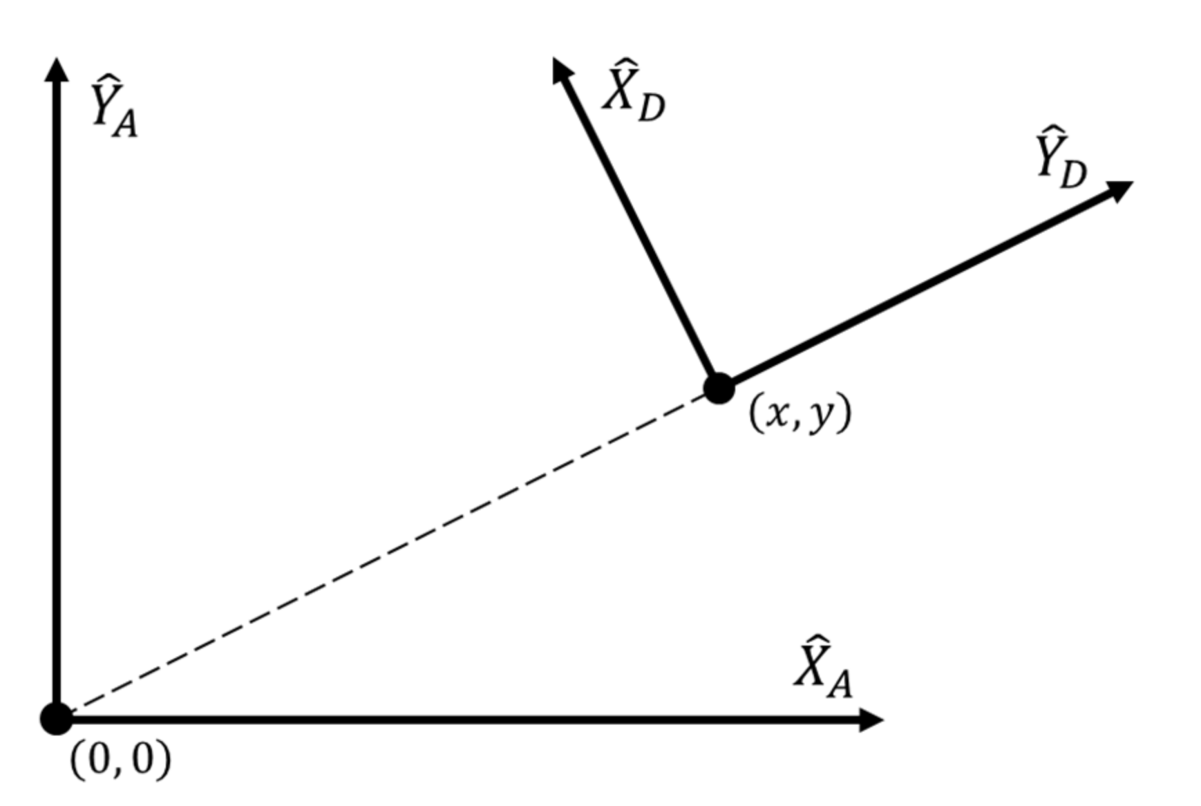
In
Figure 8,
is perpendicular to the dashed line and
is collinear with the dashed line. Therefore, Equation (18) can be rewritten as the following equation, with unknowns (
a,
b,
c,
d),
6.2. Measurement Data
In the present experiment, the manipulator was manually controlled and the screw manually aligned over each screw hole. Camera 2 took 12 pictures of each screw hole. The coordinates (
XC2,
YC2) of the screw holes were determined using these 12 pictures (
Table 3). The average values indicate the correct position of the screw hole.
If it needs speedy time, we can reduce the number of detections. At least four (
) and (
) data points were required to solve for the four unknowns. The manipulator was manually controlled to align the screw at the No. 6 screw hole, after which it was moved 1 mm forward, backward, left, and right. Camera 2 took a picture of the manipulator in each of these positions. The coordinates of the screw hole were calculated using these five pictures. The same steps were performed for the No. 12 screw hole.
Table 4 and
Table 5 list the measurement data for these two screw holes. For the No. 6 screw hole, (
x,
y) = (427.5, −42.1). For the No. 12 screw hole, (
x,
y) = (395.57, 46).
6.3. Calculation
Variables
u and
v are defined as follows,
The 10 data points in
Table 4 and
Table 5 were substituted into Equation (19),
Variables
u and
v were moved to the left matrix:
The equations were simplified,
The {
D} data matrices are represented by
D1 and
D2. The {
A} data matrices are represented by
AX and
AY. With the 10 data points, the four unknowns were solved using the least square method.
The elements of rotation matrix
R were then calculated,
The matrix is not completely symmetrical, and its slight error is caused by the fact that the inside of the robot arm is not an absolute coordinate system.
Through the automatic process, the coordinates of the screw hole are solved using image processing. These coordinates and the current coordinates of the manipulator (x, y) can be substituted into Equation (19) and automatically transformed into coordinates in the manipulator’s coordinate system.
During real-time implementation, the parameter values of mathematical equations are given in Equations (15) and (30). Using these equations, we can execute the real-time implementation in experiments.
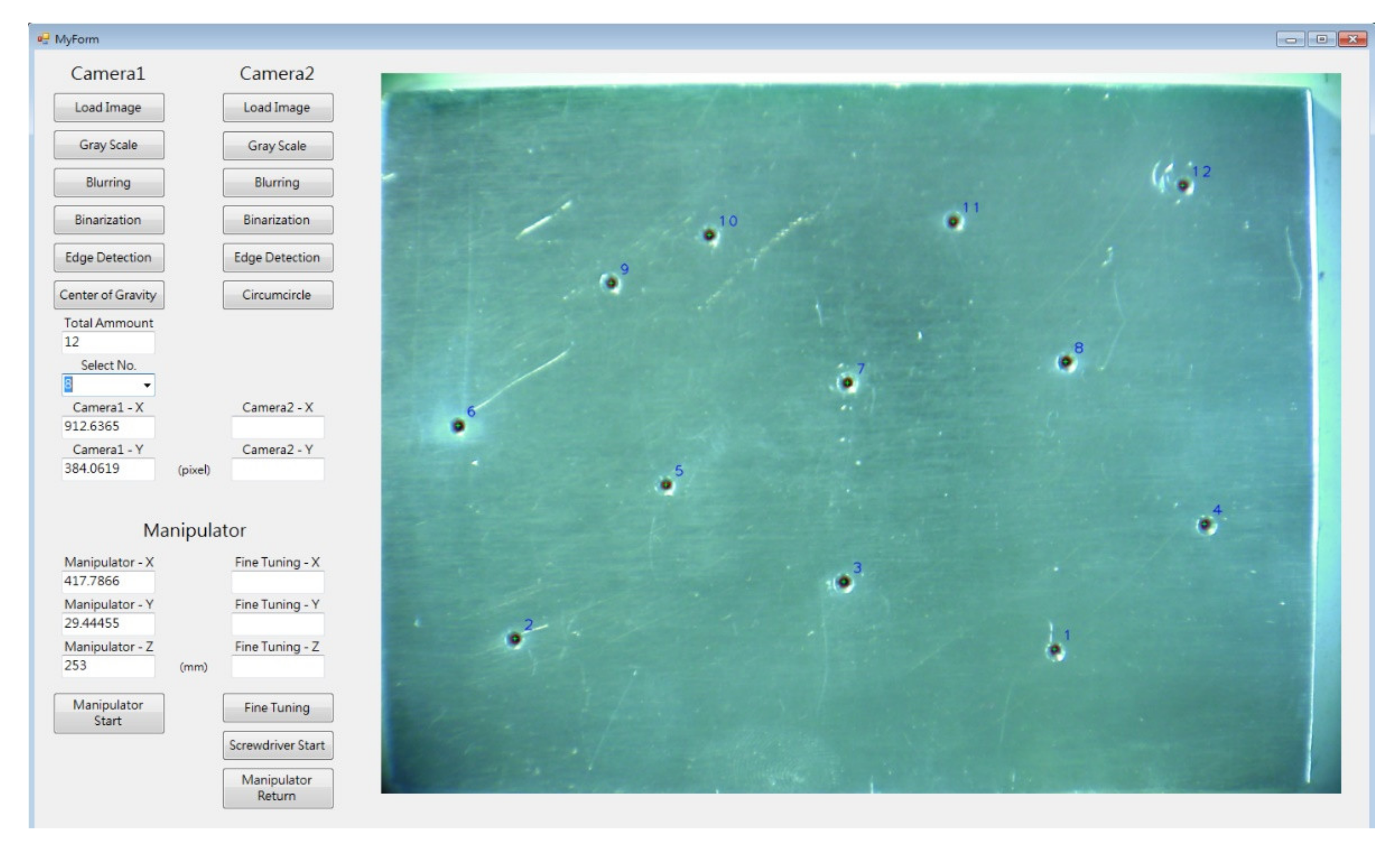
7. Program and Experiment Process
The camera photographs the screw hole. The image is processed and the coordinate value is then transformed through the HMI. The manipulator controller and the HMI communicate through the RS232. The dc motor in the electric screwdriver was controlled in this study by an Arduino UNO. The Arduino and HMI communicated through a Universal Serial Bus connection.
Figure 9 displays the HMI, which has buttons and text boxes as well as an image of all the screw holes. First, the user randomly moves the screw hole workpiece. The workpiece should be in the shooting range of Camera 1. After Camera 1 photographs the workpiece, the image is processed using the methods described in
Section 2: gray scale, Gaussian filter, bilateral filter, binarization, edge detection, and center of gravity. The system detects 12 screw holes. If the user chooses the No. 8 screw hole, the system calculates its coordinates and then transforms them into the coordinate system of the manipulator, with the resulting coordinates displayed by the HMI. When the user presses the button “Manipulator Start,” the manipulator moves to the intended position automatically, which in this case is a fixed height above the No. 8 screw hole.
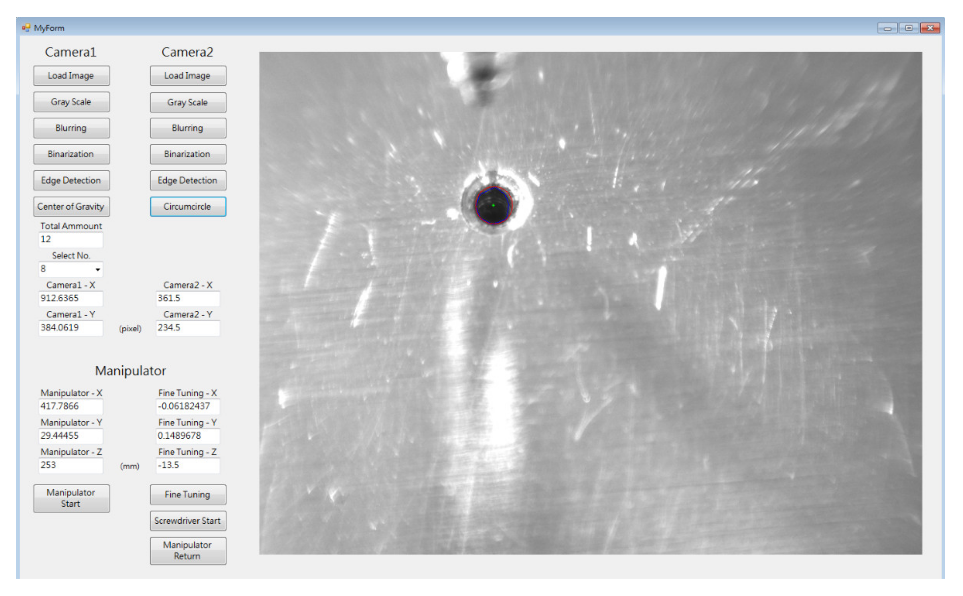
After the manipulator has arrived at the calculated position, Camera 2 photographs the No. 8 screw hole. The image is processed, and the system detects the screw hole and calculates its coordinates, transforming them into the coordinate system of the manipulator. The HMI displays the coordinates, as shown in
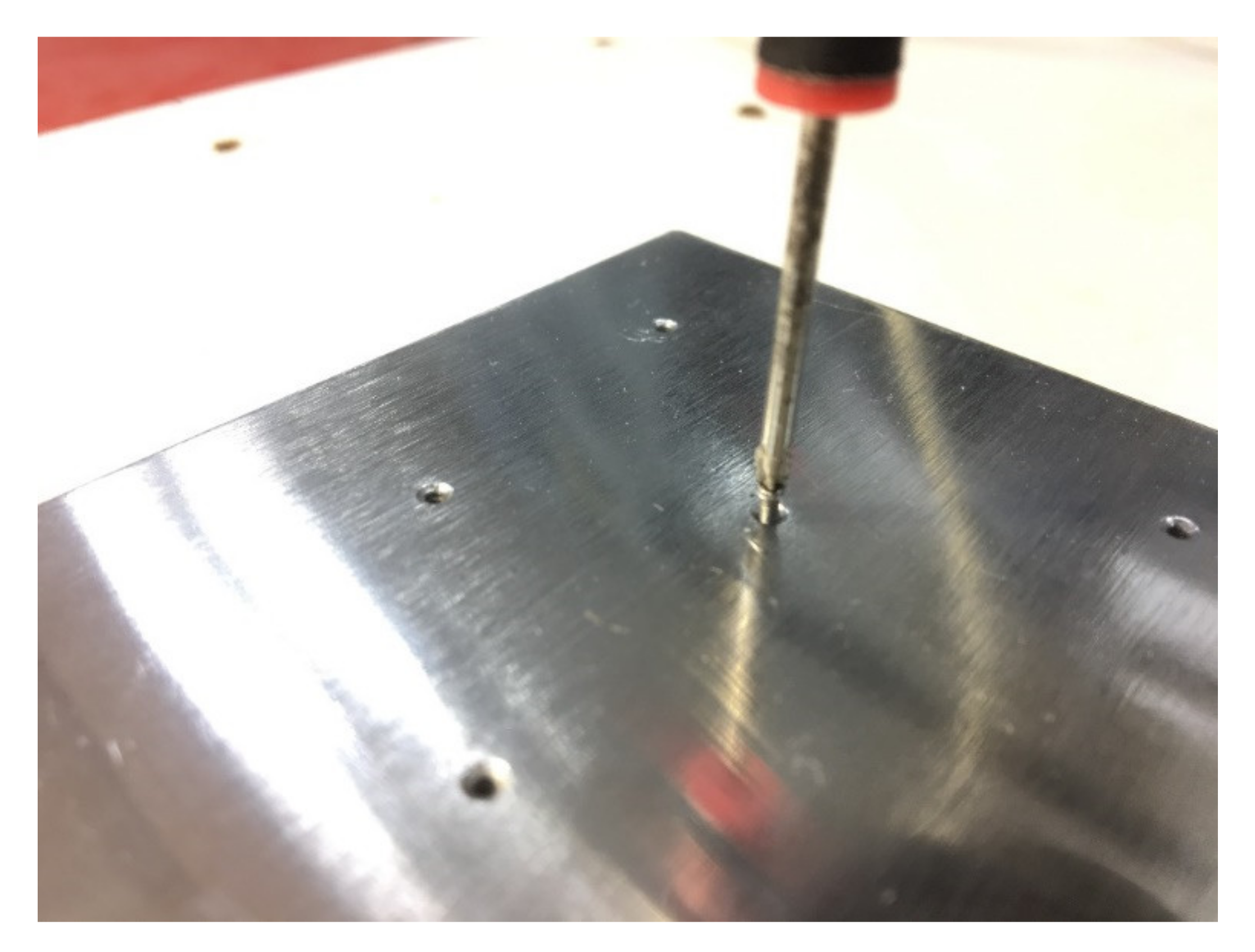
Figure 10. When the user presses the button “Manipulator Start,” the manipulator moves to the determined position automatically, so that the screw touches the No. 8 screw hole vertically. When the user presses the button “Screwdriver Start,” the dc motor in the electric screwdriver starts rotating, tightening the screw into the screw hole (
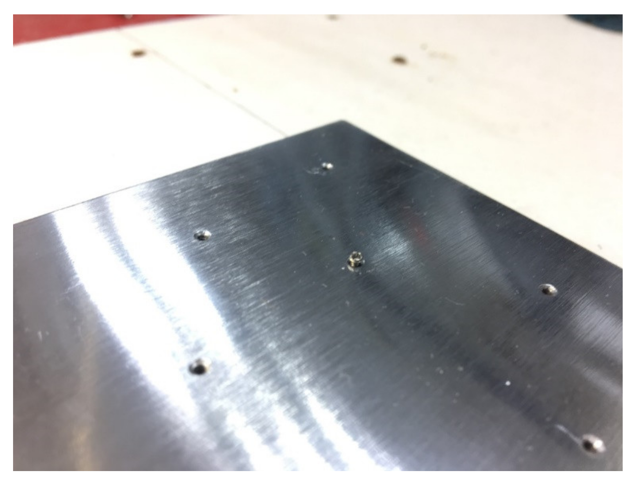
Figure 11). When the user presses the button “Manipulator Return,” the manipulator returns to its initial position (
Figure 12).
8. Conclusions
The proposed approach tightens an M1.4 screw automatically. The cost for Digital Image Processing on a general computer is about 0.5 s, for the manipulator with slow motion is about 5 s, and for the fast motion is about 2 s instead. In contrast with manual labor, automatically tightening screw manipulators is faster, and would not affect the success rate from fatigue. The success rate is about 80% in this study. The failure is mainly due to the fact that the screw is not properly be positioned in the screwdriver head since the screw is secured to the screwdriver head by magnetizing the screw head. Since there is no other research related to tightening tiny screws, we cannot provide performance indicators to compare with other studies. Future work will continue to explore the extension of the scheme to curved 3-D Car-body-like-surfaces.
Author Contributions
Conceptualization, P.-C.T.; methodology, C.-K.L., J.-R.H. and P.-C.T.; investigation, S.-Y.C.; resources, C.-K.L., J.-R.H. and P.-C.T.; data curation, P.-C.T.; writing—original draft preparation, S.-Y.C. and P.-C.T.; writing—review and editing, J.-R.H. and C.-K.L.; project administration, J.-R.H. and C.-K.L.; funding acquisition, P.-C.T. and C.-K.L. All authors have read and agreed to the published version of the manuscript.
Funding
This work was funded by the Ministry of Science and Technology (Taiwan) under contract numbers MOST 110-2218-E-008-008 and MOST 110-2221-E-008-089.
Institutional Review Board Statement
Not applicable.
Informed Consent Statement
Not applicable.
Data Availability Statement
Not applicable.
Conflicts of Interest
The authors declare no conflict of interest. The funders had no role in the design of the study; in the collection, analyses, or interpretation of data; in the writing of the manuscript or in the decision to publish the results.
References
- Brogårdh, T. Present and future robot control development—An industrial perspective. Annu. Rev. Control. 2007, 31, 69–79. [Google Scholar] [CrossRef]
- Asakawa, N.; Takeuchi, Y. Teachingless spray-painting of sculptured surface by an industrial robot. In Proceedings of the 1999 IEEE International Conference on Robotics and Automation (Cat. No.99CH36288C), Detroit, MI, USA, 10–15 May 1999. [Google Scholar]
- Choi, S.; Newman, W.S. Design and evaluation of a laser-cutting robot for laminated, solid freeform fabrication. In Proceedings of the 2000 ICRA. Millennium Conference. IEEE International Conference on Robotics and Automation. Symposia Proceedings (Cat. No.00CH37065), San Francisco, CA, USA, 24–28 April 2000. [Google Scholar]
- Smith, C.B. Robotic friction stir welding using a standard industrial robot. Keikinzoku Yosetsu/J. Light Met. Weld. Constr. 2004, 42, 40–41. [Google Scholar]
- Nagata, F.; Watanabe, K.; Kiguchi, K.; Tsuda, K.; Kawaguchi, S.; Noda, Y.; Komino, M. Joystick teaching system for polishing robots using fuzzy compliance control. In Proceedings of the 2001 IEEE International Symposium on Computational Intelligence in Robotics and Automation, Banff, AB, Canada, July 29–1 August 2001. [Google Scholar]
- Zheng, Y.F.; Luh, J. Optimal load distribution for two industrial robots handling a single object. In Proceedings of the IEEE International Conference on Robotics and Automation, Philadelphia, PA, USA, 24–29 April 1988; pp. 344–349. [Google Scholar]
- Pitipong, S.; Pornjit, P.; Watcharin, P. An automated four-DOF robot screw fastening using visual servo. In Proceedings of the 2010 IEEE/SICE International Symposium on System Integration, Sendai, Japan, 21–22 December 2010. [Google Scholar]
- Schmid, A.J.; Gorges, N.; Goger, D.; Worn, H. Opening a door with a humanoid robot using multi-sensory tactile feedback. In Proceedings of the 2008 IEEE International Conference on Robotics and Automation, Pasadena, CA, USA, 19–23 May 2008; pp. 285–291. [Google Scholar]
- Prats, M.; Sanz, P.J.; Del Pobil, A.P. Vision-tactile-force integration and robot physical interaction. In Proceedings of the 2009 IEEE International Conference on Robotics and Automation, Kobe, Japan, 12–17 May 2009; pp. 3975–3980. [Google Scholar]
- Otsu, N. A Threshold Selection Method from Gray-Level Histograms. IEEE Trans. Syst. Man Cybern. 2007, 9, 62–66. [Google Scholar] [CrossRef] [Green Version]
- Bliton, A.; Patton, M.; Rolli, M.; Roos, K.; Taylor, S. Microscopic motion analysis: Laplacian-of-Gaussian masks for subpixel edge detection. In Proceedings of the Annual International Conference of the IEEE Engineering in Medicine and Biology Society, New Orleans, LA, USA, 4–7 November 1988; pp. 1098–1099. [Google Scholar]
- Zare, M.; Jampour, M.; Farrokhi, I.R. A heuristic method for gray images pseudo coloring with histogram and RGB layers. In Proceedings of the 2011 IEEE 3rd International Conference on Communication Software and Networks, Xi’an, China, 27–29 May 2011; pp. 524–527. [Google Scholar]
- Pratt, W.K. Digital Image Processing: PIKS Inside, 3rd ed.; John Wiley: New York, NY, USA, 2001. [Google Scholar]
- Wennersten, P.; Ström, J.; Wang, Y.; Andersson, K.; Sjoberg, R.; Enhorn, J. Bilateral filtering for video coding. In Proceedings of the 2017 IEEE Visual Communications and Image Processing (VCIP), St. Petersburg, FL, USA, 10–13 December 2017; pp. 1–4. [Google Scholar]
- Ma, Z.; Zhu, J.; Li, W.; Xu, H. Detection of point sources in X-ray astronomical images using elliptical Gaussian filters. In Proceedings of the 2017 2nd International Conference on Image, Vision and Computing (ICIVC), Chengdu, China, 2–4 June 2017; pp. 36–40. [Google Scholar]
| Publisher’s Note: MDPI stays neutral with regard to jurisdictional claims in published maps and institutional affiliations. |
© 2021 by the authors. Licensee MDPI, Basel, Switzerland. This article is an open access article distributed under the terms and conditions of the Creative Commons Attribution (CC BY) license (https://creativecommons.org/licenses/by/4.0/).


