
Generative Design for Dimensioning of Retaining Walls


Abstract
1. Introduction
2. Materials and Methods
3. Results and Discussions
3.1. Problem/Solution Identification
- Work with the active condition, equivalent to using a retention coefficient equal to unity (Cr = 1,0) [8].
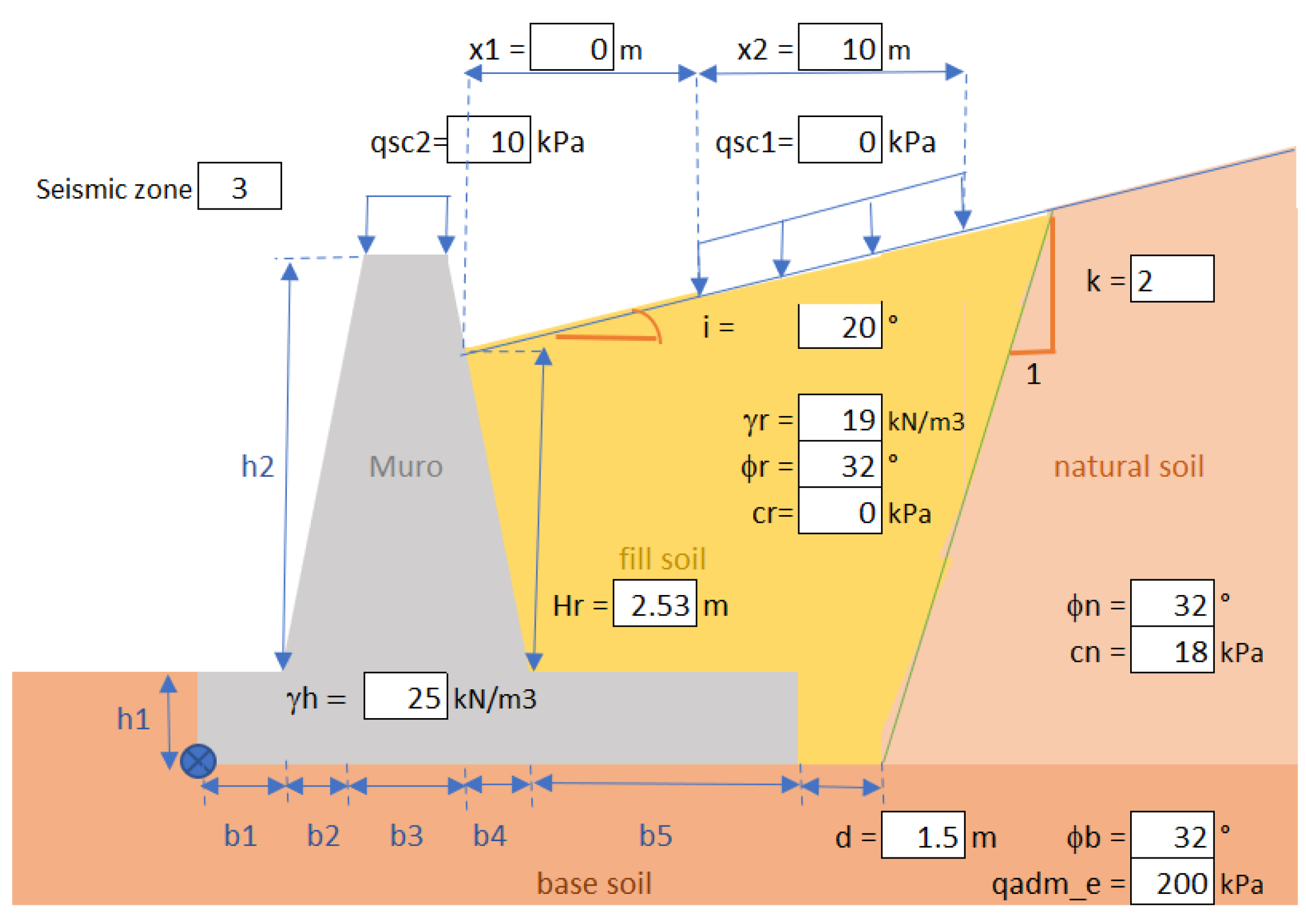
- Define the static soil thrusts, with their respective variables and the correction of retained soil parameters, depending on whether an imaginary line of 45º to the horizontal passes only through the fill or, on the contrary, also crosses the existing natural soil or fill. In the latter case, the cohesion and friction angle must be weighted to an equivalent cohesion and friction angle, c* and ϕ*, respectively [8].
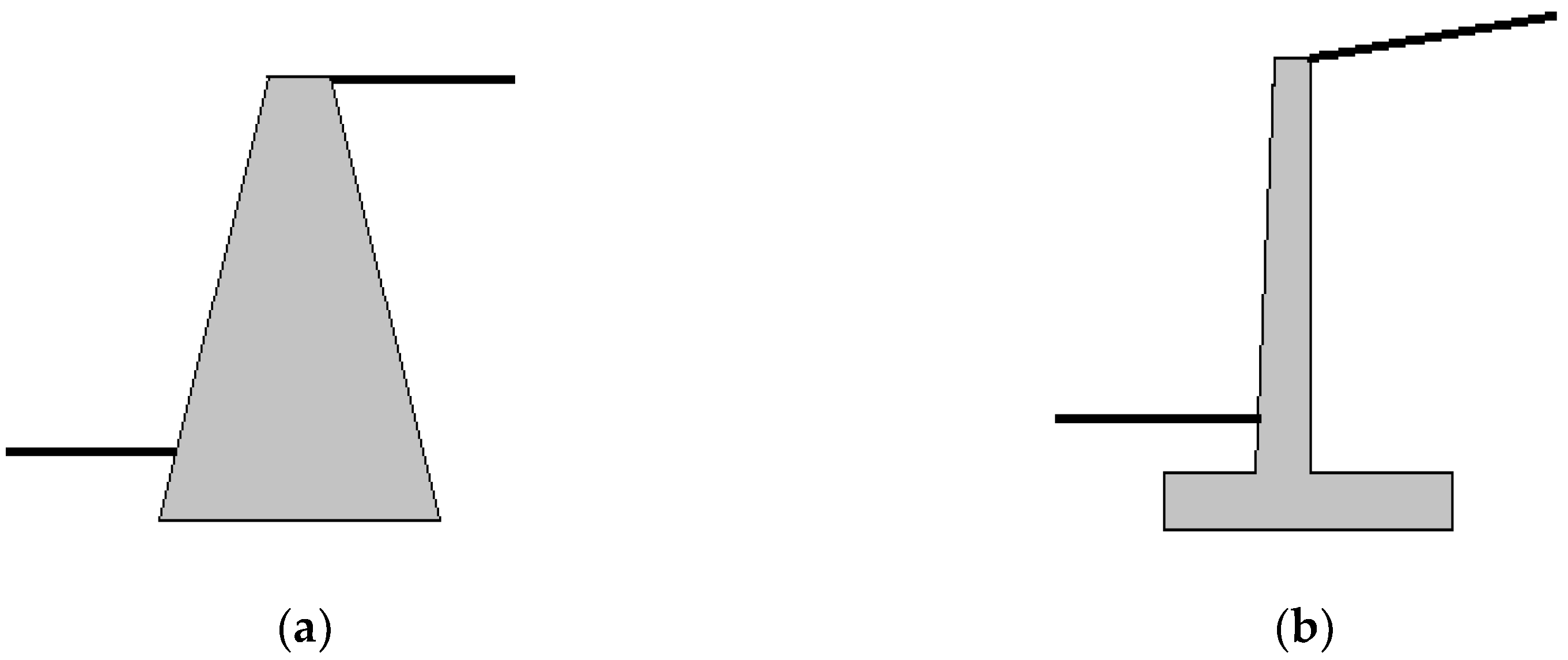
- Consider a triangular distribution and the different parameters to calculate the static soil thrusts in both a gravity wall and a cantilever, including the respective static thrust coefficient (Ke) [8].
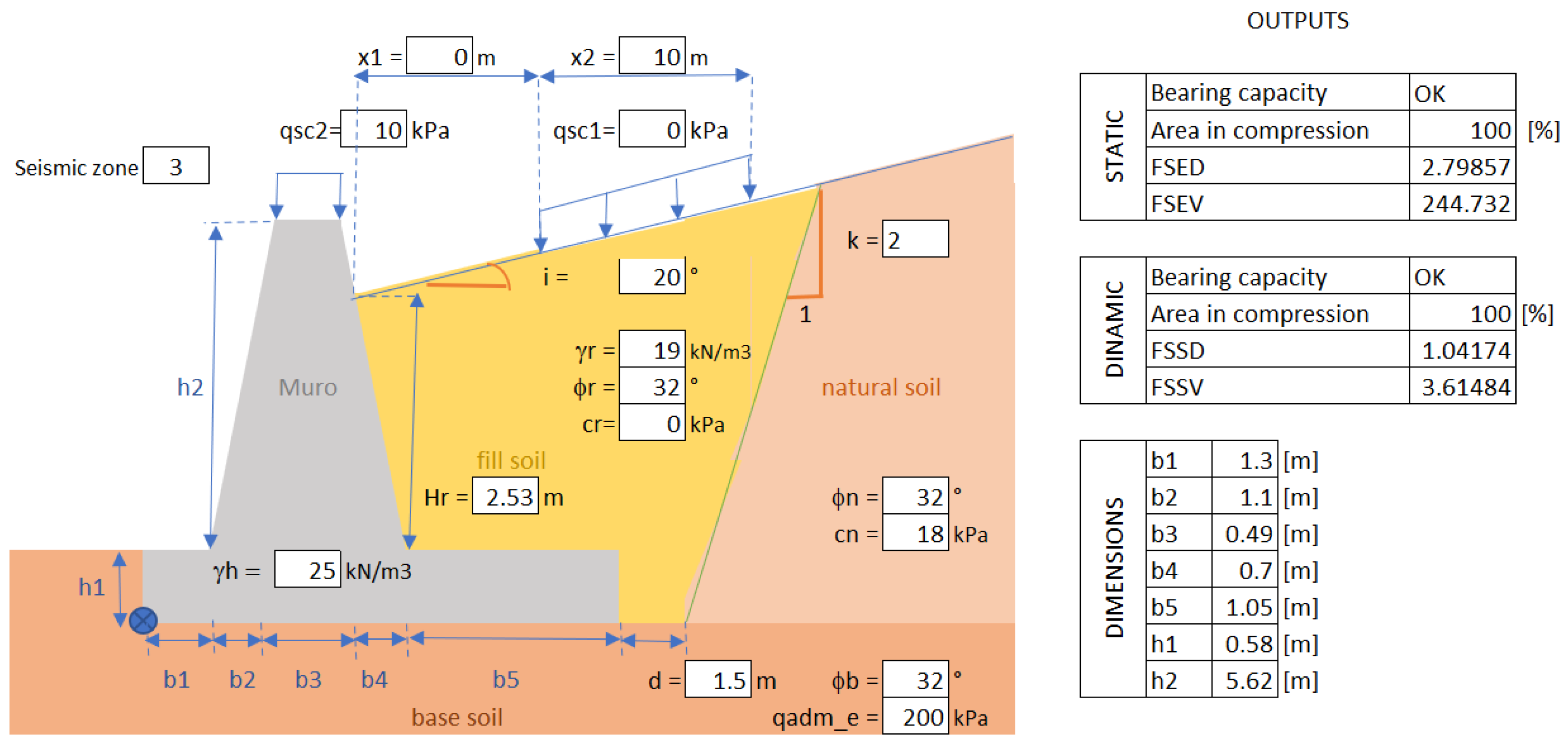
- Ensure that the static slip factor of safety (FSED) and the static overturning factor of safety (FSEV) are greater than or equal to 1.5 (Equations (1) and (2)); for this purpose, Ke based on Coulomb theory was used [8].
- For the seismic soil thrusts, expressions based on Mononobe and Okabe were used, which were superimposed on the static thrusts, according to a pseudo-static approximation [8].
- An inverted triangular distribution for the backfill and a rectangular distribution for the overburden (conservative assumption) were considered, as well as the different parameters to calculate the seismic soil thrusts in both a gravity wall and a cantilever, including the seismic thrust coefficient (Ks) [8].
- In addition, it was verified that the seismic slip factor of safety (FSSD) was at least 1.1, and the seismic overturning factor of safety (FSSV) was greater than 1.15 times the FSSD [8].
- Finally, it was estimated that the area in compression of the foundation seal should exceed 80% [8].
- Does the program fulfill the design of retaining walls?
- Does it deliver solutions that satisfy the requirements of the corresponding regulations?
- Is the program user-friendly?
- Does it work for people who are not familiar with generative design?
- Does the program have advantages over traditional retaining wall design (according to the users’ opinion)?
3.2. Solution Design and Development
3.3. Verification and Validation—Usability Tests
4. Conclusions
Supplementary Materials
Author Contributions
Funding
Institutional Review Board Statement
Informed Consent Statement
Data Availability Statement
Acknowledgments
Conflicts of Interest
References
- Brooks, H.; Nielsen, J. Basics of Retaining Wall Design, 10th ed.; HBA Publication: Newport Beach, CA, USA, 2013. [Google Scholar]
- Prada, F.; Ramos, A.; Solaque, D.; Caicedo, B. Confiabilidad aplicada al diseño geotécnico de un muro de contención. Obras Proy. 2011, 9, 49–58. [Google Scholar] [CrossRef]
- Khan, F.; Zamiran, S.; Osouli, A. Comparison of Seismic Response of Gravity and Cantilever Walls Backfilled with Dirty Coarse-Grained Material. In Proceedings of the Geo-Congress 2019, Reston, VA, USA, 24–27 March 2019; American Society of Civil Engineers: Reston, VA, USA, 2019; pp. 57–65. [Google Scholar]
- Lucero Pardo, F.H.; Pachacama Caiza, E.A.; Rodriguez Montero, W.A. Analisis y Diseño de Muros de Contención; Universidad Central del Ecuador: Quito, Ecuador, 2012. [Google Scholar]
- Fenton, G.A.; Griffiths, D.V.; Williams, M.B. Reliability of traditional retaining wall design. Géotechnique 2005, 55, 55–62. [Google Scholar] [CrossRef]
- Madabhushi, S.P.G.; Zeng, X. Seismic response of flexible cantilever retaining walls with dry backfill. Geomech. Geoengin. 2006, 1, 275–289. [Google Scholar] [CrossRef]
- Gandomi, A.H.; Kashani, A.R.; Roke, D.A.; Mousavi, M. Optimization of retaining wall design using recent swarm intelligence techniques. Eng. Struct. 2015, 103, 72–84. [Google Scholar] [CrossRef]
- MOP Volumen N°3. Instrucciones y Criterior de Diseño. In Manual de Carreteras; Ministerio de Obras Públicas: Santiago, Chile, 2014; Volume 3, p. 1285. [Google Scholar]
- Hooley, I.W.; Al-Deen, S. Design of cantilever retaining walls for minimum tilting tendency. Aust. J. Struct. Eng. 2020, 21, 1–9. [Google Scholar] [CrossRef]
- Velasco Pérez, R. Estudio de la Aplicación del Diseño Generativo al Diseño Conceptual Arquitectónico; Universitat Politecnica de Valencia: Valencia, Spain, 2015. [Google Scholar]
- Kalemci, E.N.; İkizler, S.B.; Dede, T.; Angın, Z. Design of reinforced concrete cantilever retaining wall using Grey wolf optimization algorithm. Structures 2020, 23, 245–253. [Google Scholar] [CrossRef]
- Díaz, G.; Herrera, R.F.; Muñoz-La Rivera, F.C.; Atencio, E. Applications of generative design in structural engineering. Rev. Ing. Construcción 2021, 36, 29–47. [Google Scholar] [CrossRef]
- McKnight, M. Generative Design: What it is? How is it being used? Why it’s a game changer. KnE Eng. 2017, 2, 176. [Google Scholar] [CrossRef]
- Khan, S.; Awan, M.J. A generative design technique for exploring shape variations. Adv. Eng. Inform. 2018, 38, 712–724. [Google Scholar] [CrossRef]
- Tafraout, S.; Bourahla, N.; Bourahla, Y.; Mebarki, A. Automatic structural design of RC wall-slab buildings using a genetic algorithm with application in BIM environment. Autom. Constr. 2019, 106, 102901. [Google Scholar] [CrossRef]
- Van Telgen, M. Exploring Structural Design Options Using Generative Design. Available online: https://dynamobim.org/exploring-structural-design-options-using-generative-design/ (accessed on 9 August 2021).
- Abdallah, H.; Ezzedine, F.; Haddad, A.; Salami, G.; Sanboskani, H.; Dabaghi, M.; Hamzeh, F. Employing Generative Design for Sustainable Construction; Budapest University of Technology and Economics: Budapest, Hungary, 2019; pp. 692–698. [Google Scholar] [CrossRef]
- García Alvarado, R.; Lyon Gottlieb, A. Diseño paramétrico en Arquitectura; método, técnicas y aplicaciones. Arquisur 2013, 31, 20–31. [Google Scholar] [CrossRef]
- Johan, R.; Chernyavsky, M.; Fabbri, A.; Gardner, N.; Haeusler, M.H.; Zavoleas, Y. Building Intelliengence through Generative design: Structural Analysis and Optimisation Informed by Material Performance. In Proceedings of the 24th International Conferences of the Association for Computer-Aided Architectural Design Research in Asia (CAADRIA), Wellington, New Zealand, 15–18 April 2019; Volume 1, pp. 371–380. [Google Scholar]
- Turney, D. Concrete Forms Get Stronger, Lighter, and More Sustainable with Generative Design. Available online: https://redshift.autodesk.com/sustainable-concrete/ (accessed on 9 August 2021).
- Hevner, A.R. A three cycle view of design science research. Scand. J. Inf. Syst. 2007, 19, 87–92. Available online: http://aisel.aisnet.org/sjis/vol19/iss2/4 (accessed on 9 August 2021).
- Hevner, A.R.; Chatterjee, S. Design science research frameworks. In Design Sicence Research in Information Systems; Springer: Boston, MA, USA, 2010; pp. 23–31. [Google Scholar]
- Guevara Anzules, M. Estudio Comparativo del Análisi de Muros de Contención Tanto Como, muro en Voladizo vs. Muro de Contrafuertes, de un muro de altura = 7.5 m, Tanto en su Análisis Estructural Como en su Análisi técnico-Económico; Universidad de Guayaquil: Guayaquil, Ecuador, 2009. [Google Scholar]
- Trivedi, P.; Sharma, A. A comparative study between iterative waterfall and incremental software development life cycle model for optimizing the resources using computer simulation. In Proceedings of the 2013 2nd International Conference on Information Management in the Knowledge Economy, Chandigarh, India, 19–20 December 2013; Institute of Electrical and Electronics Enginers (IEEE): Chandigarh, India, 2013; pp. 188–194. [Google Scholar]
- Das, B.M.; Sivakugan, N. Fundamentals of Geothecnical Engineering, 5th ed.; Cengage Learning: Boston, MA, USA, 2016. [Google Scholar]
- Nielsen, J.; Landauer, T.K. A mathematical model of the finding of usability problems. In Proceedings of the ACM INTERCHI’93 Conference, Amsterdam, The Netherlands, 24–29 April 1993; IOS Press: Amsterdam, The Netherlands, 1993; pp. 206–213. [Google Scholar]


| Stage | Name | Description |
|---|---|---|
| 1 | Confidentiality agreement | Agreement to participate in the user test and disclosure of results. |
| 2 | General information | Explanation about the program being evaluated and not its skills. In addition, the following steps were described. |
| 3 | Preliminary questionnaire | Identification of the participant: age, educational level, knowledge of generative design, familiarity with the software to be used, and capacity to design retaining walls. |
| Iteration | Activity |
|---|---|
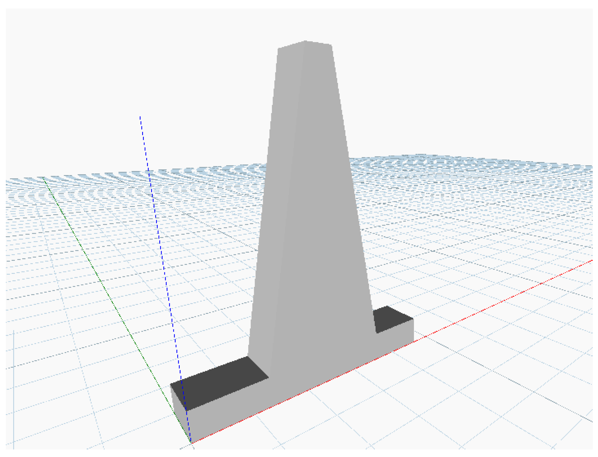
| First | Development of the 3D parametric model of the retaining wall |
| Second | Enter inputs |
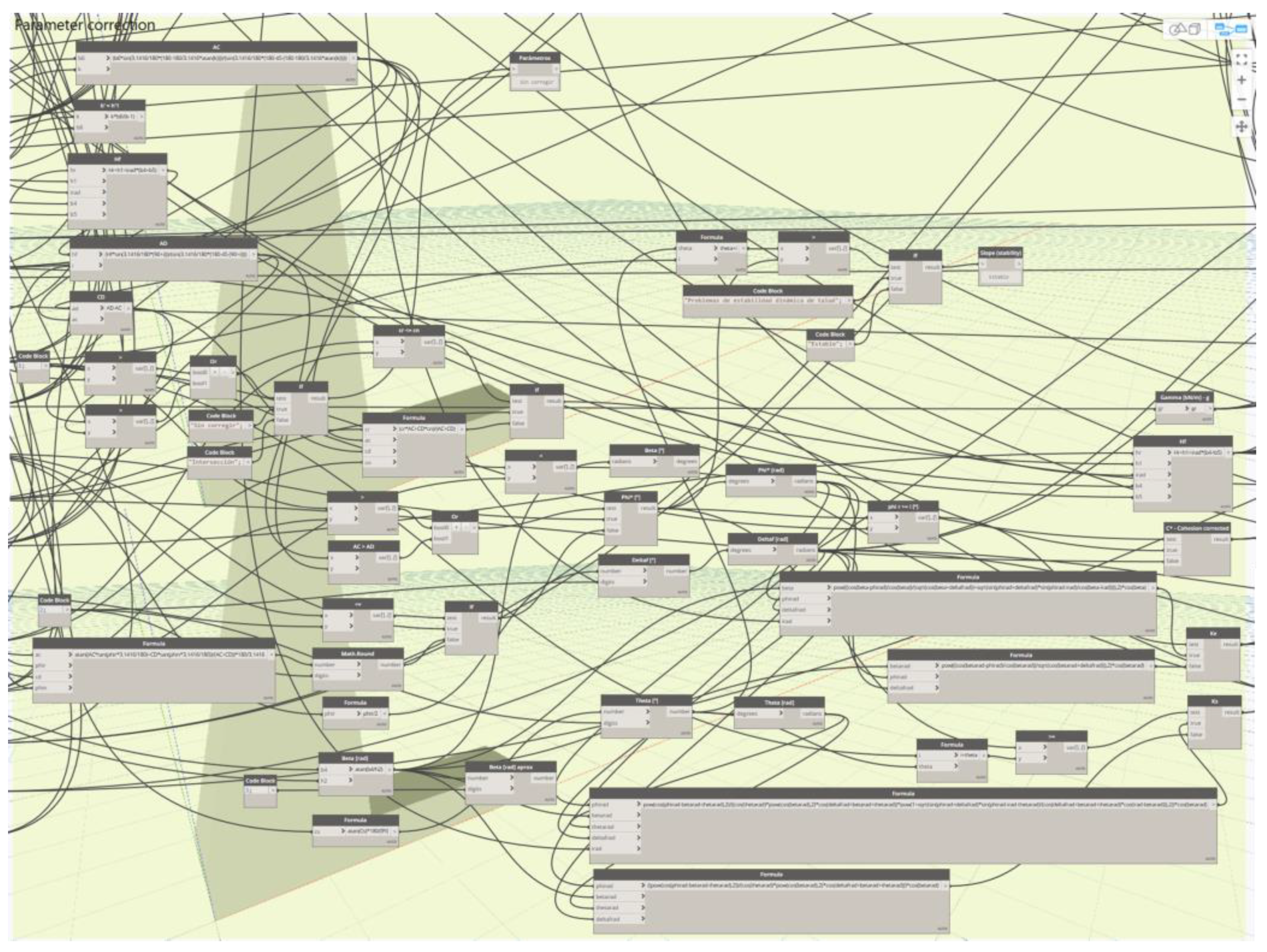
| Third | Internal calculations (mathematical algorithm) |
| Fourth | Transform parametric model into a generative model |
| Variable | Select | Minimize | Maximize |
|---|---|---|---|
| Total volume | ✓ | ✓ | - |
| FSED | ✓ | ✓ | - |
| FSEV | ✓ | ✓ | - |
| Area under compression | - | - | - |
| FSSD | ✓ | ✓ | - |
| Delta FSSV | ✓ | ✓ | - |
| Height restriction | - | - | - |
| Variable | Select | Minimize | Observations |
|---|---|---|---|
| Total volume | - | - | - |
| FSED | ✓ | 1.5 | According to Highway Manual, vol. 3 [8] |
| FSEV | ✓ | 1.5 | According to Highway Manual, vol. 3 [8] |
| Area under compression | ✓ | 80 | According to Highway Manual, vol. 3 [8] |
| FSSD | ✓ | 1.1 | According to Highway Manual, vol. 3 [8] |
| Delta FSSV | ✓ | 0 | FSSV − 1.15* FSSD > 0 |
| Height restriction | ✓ | 0 | The height of the screen must be greater than the fill height |
| Task | Average Execution Time [minutes] |
|---|---|
| Open corresponding Revit file | 5 |
| Enter input data MS Excel | 2 |
| Create generative design study | 2 |
| Choose design goals | 1 |
| Choose appropriate constraints | 2 |
| Create solutions | 5 |
| Obtain output data | 6 |
| Total | 23 |
Publisher’s Note: MDPI stays neutral with regard to jurisdictional claims in published maps and institutional affiliations. |
© 2021 by the authors. Licensee MDPI, Basel, Switzerland. This article is an open access article distributed under the terms and conditions of the Creative Commons Attribution (CC BY) license (https://creativecommons.org/licenses/by/4.0/).
Share and Cite
Díaz, G.; Herrera, R.F.; Muñoz-La Rivera, F.; Atencio, E. Generative Design for Dimensioning of Retaining Walls. Mathematics 2021, 9, 1918. https://doi.org/10.3390/math9161918
Díaz G, Herrera RF, Muñoz-La Rivera F, Atencio E. Generative Design for Dimensioning of Retaining Walls. Mathematics. 2021; 9(16):1918. https://doi.org/10.3390/math9161918
Chicago/Turabian StyleDíaz, Gabriel, Rodrigo F. Herrera, Felipe Muñoz-La Rivera, and Edison Atencio. 2021. "Generative Design for Dimensioning of Retaining Walls" Mathematics 9, no. 16: 1918. https://doi.org/10.3390/math9161918
APA StyleDíaz, G., Herrera, R. F., Muñoz-La Rivera, F., & Atencio, E. (2021). Generative Design for Dimensioning of Retaining Walls. Mathematics, 9(16), 1918. https://doi.org/10.3390/math9161918