
Eliminating Stick-Slip Vibrations in Drill-Strings with a Dual-Loop Control Strategy Optimised by the CRO-SL Algorithm

 , ,
, ,  , and
, and 
Abstract
:
1. Introduction
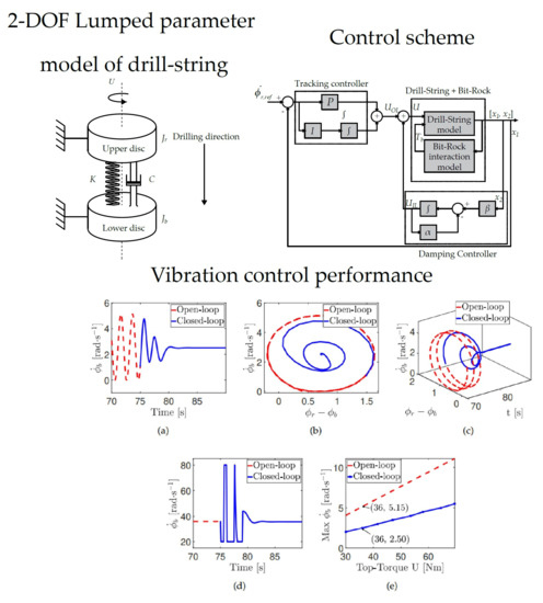
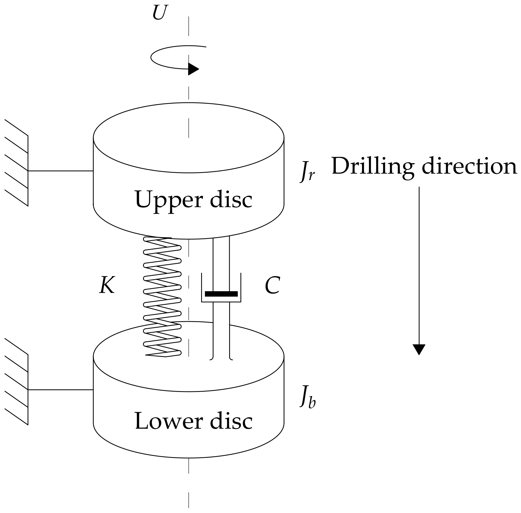
2. System Model
2.1. Mathematical Model
2.2. Bit–Rock Interaction
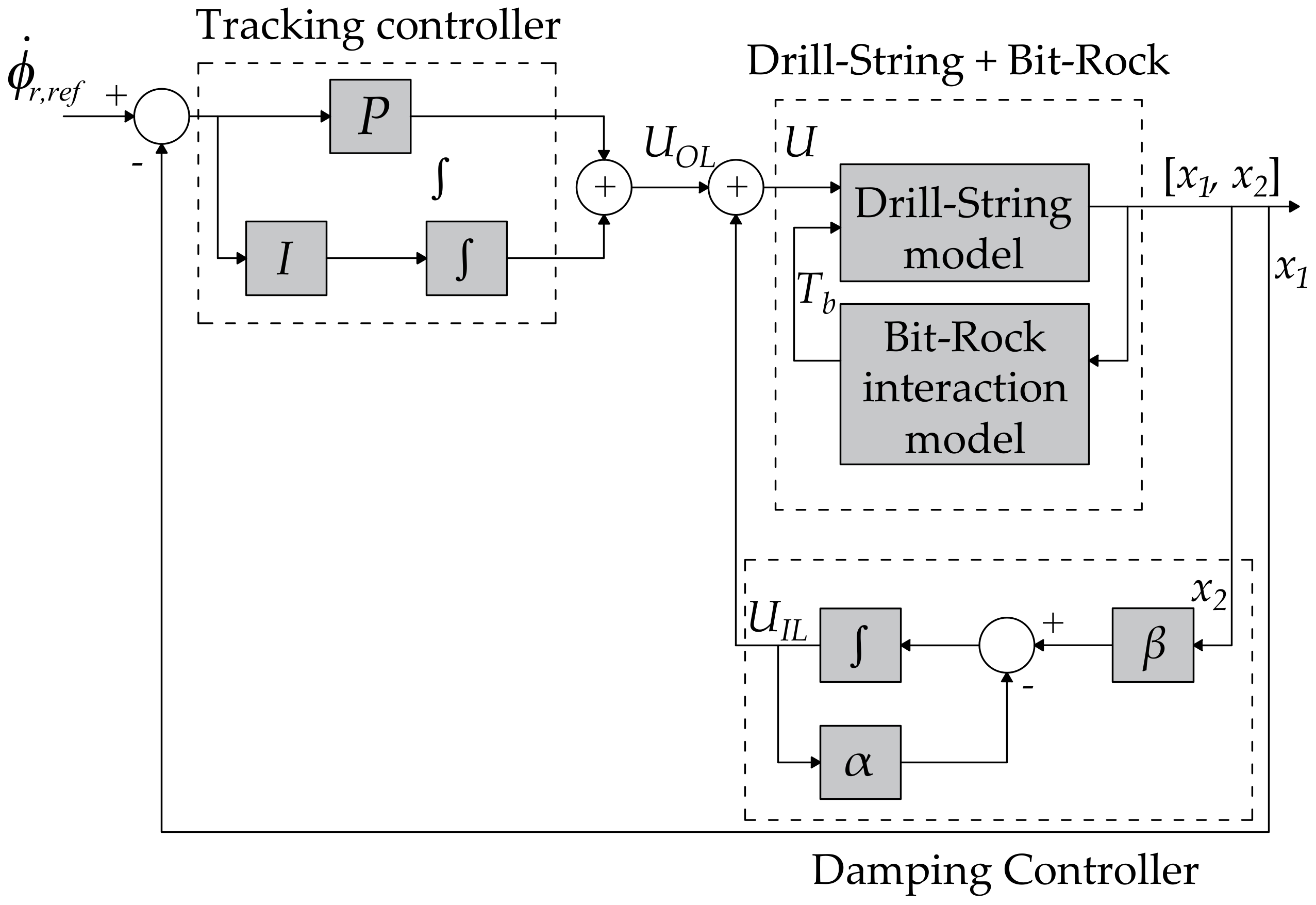
3. Control Design and Parameter Optimisation
- : The steady-state error between the desired (top-drive) and achieved (drill-bit) angular velocity .
- : The residual vibration .
- : The settling time of the variables and
- : The control effort from a determined value of time, which rejects solutions with chattering.
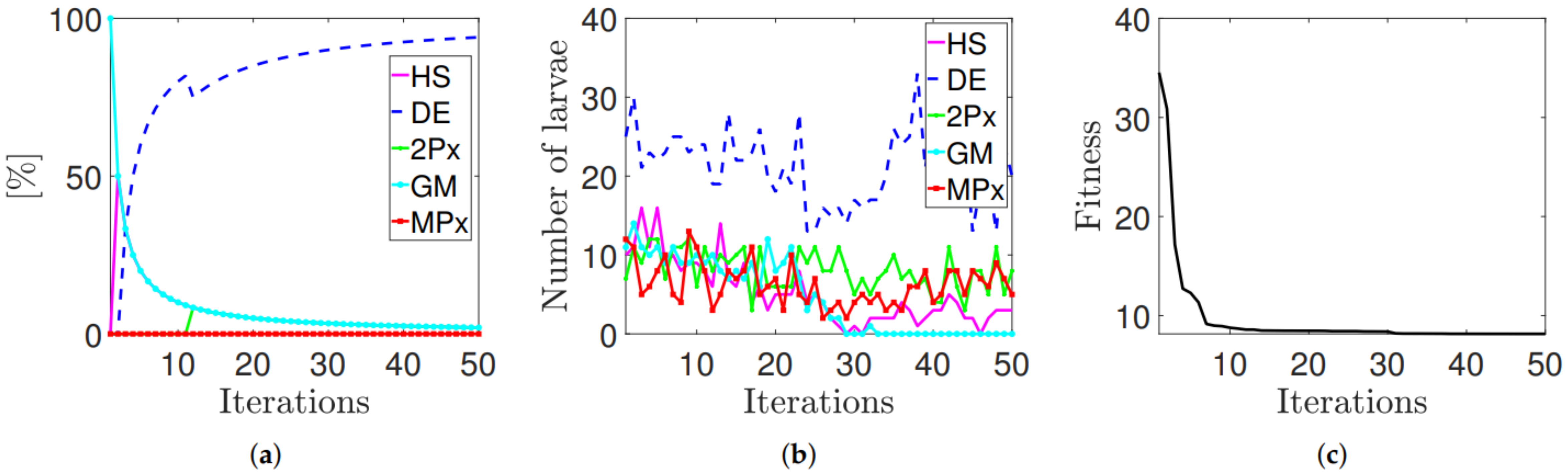
Coral Reefs Optimisation Algorithm with Substrate Layer: A Multi-Method Ensemble Approach
| Algorithm 1 Pseudo-code for the original CRO |
| Require: Valid configuration of parameters controlling the CRO algorithm Ensure: A single individual with near-optimal value of its fitness
|
- Harmony Search (HS): It is a metaheuristic method based on stochastic optimisation [38]. It imitates the process found in music improvisation, which searches for better harmony. There are two parameters that determine the way in which new larvae are generated: (i) Harmony Memory Considering Rate (HMCR), which ranges from zero to one. If a uniformly spawned value is above the value of HMCR, then the encoded parameter value is uniformly drawn from the values in the coral, (ii) Pitch Adjusting Rate (PAR), which ranges from zero to one, which sets the probability of choosing a neighbour value of the current larva.
- Differential Evolution (DE): It is an Evolutionary Algorithm (EA), which has good abilities for global search [63]. The new larvae can be generated either by the mutation or crossover process. For a randomly selected encoded parameter, if a uniformly generated value is above the Crossover Probability (CR) value, which ranges from zero to one, the new value is obtained by , in which F is the evolution factor. Otherwise, the value is crossed with the randomly selected encoded parameter.
- Classical 2-points crossover (2Px): The crossover operator is the most used exploration mechanism in genetic and evolutionary algorithms [64] since its combination with an efficient mutation process allows achieving a suitable balance between exploration and exploitation. 2Px selects two random parents and exchanges the genetic material in-between two random points on them. Despite that each substrate is linked to a searching process, when another parent must be picked, the selection is not limited to their substrate, but it can be chosen from any part of the population instead. The reason is to contribute to genetic information exchange among substrates so they can easily cooperate.
- Multi-points crossover (MPx): This search method is a generalisation of the 2Px. In this case, k points are selected in the parents. In this work, due to the dimensionality of the problem, the value of k has been chosen to be three. Thus, a binary vector decides whether the parts of each parent are exchanged or not for the new offspring generation.
- Gaussian Mutation (GM): The Gaussian Mutation is a noisy search method based on adding random values from the Gaussian distribution to the encoded parameter values, thus generating an offspring. The standard deviation value in this work is linearly decreasing during the run, from to , where is the domain search. The Gaussian probability density function is:With the aim of exploring the search space at the beginning of the optimisation process and exploiting it at the end, the parameter is adapted during the simulation.
4. Computational Evaluation
- , , and ;
- = 40 s and = 120 s;
- N is the result of using a 0.001 s of sampling time. The simulation is carried out by a fourth-order ordinal differential equation solver (Runge–Kutta) with fixed time of 0.001 s (i.e., );
- The input torque is, as mentioned earlier, limited to N·m.
Results
5. Conclusions
Author Contributions
Funding
Data Availability Statement
Acknowledgments
Conflicts of Interest
References
- Brett, J.F. The genesis of bit-induced torsional drillstring vibrations. SPE Drill. Eng. 1992, 7, 168–174. [Google Scholar] [CrossRef]
- Hamaneh, S.V.V. Dynamics and Control of Nonlinear Engineering Systems. Ph.D. Thesis, University of Aberdeen, Aberdeen, UK, 2015. [Google Scholar]
- Vromen, T.; Dai, C.-H.; van de Wouw, N.; Oomen, T.; Astrid, P.; Nijmeijer, H. Robust output-feedback control to eliminate stick-slip oscillations in drill-string systems. IFAC Pap. 2015, 48, 266–271. [Google Scholar] [CrossRef]
- Navarro-López, E.M. An alternative characterization of bit-sticking phenomena in a multi-degree-of-freedom controlled drillstring. Nonlinear Anal. Real World Appl. 2009, 10, 3162–3174. [Google Scholar] [CrossRef]
- Oladunjoye, I.O.; Vaziri, V.; Ing, J.; Aphale, S.S. Severity analysis of stick-slip bifurcation in drill-string dynamics under parameter variation. Afr. Model. Simul. 2016. [Google Scholar] [CrossRef]
- Navarro-López, E.M.; Cortés, D. Avoiding harmful oscillations in a drillstring through dynamical analysis. J. Sound Vib. 2007, 307, 152–171. [Google Scholar] [CrossRef]
- Kapitaniak, M.; Hamaneh, V.V.; Chávez, J.P.; Nandakumar, K.; Wiercigroch, M. Unveiling complexity of drill-string vibrations: Experiments and modelling. Int. J. Mech. Sci. 2015, 101, 324–337. [Google Scholar] [CrossRef]
- Sugiura, J.; Jones, S. Real-time stick-slip and vibration detection for 8 1/2”-hole-size rotary steerable tools in deeper wells and more aggressive drilling. In Proceedings of the AADE National Technical Conference, Houston, TX, USA, 10–12 April 2007. [Google Scholar]
- Tucker, W.; Wang, C. On the effective control of torsional vibrations in drilling systems. J. Sound Vib. 1999, 224, 101–122. [Google Scholar] [CrossRef]
- Sugiura, J. The use of the near-bit vibration sensor while drilling lead to optimized rotary-steerable drilling in push-and point-the-bit configurations. In Proceedings of the SPE Asia Pacific Oil and Gas Conference and Exhibition, Perth, Australia, 20–22 October 2008. [Google Scholar]
- Robnett, E.; Hood, J.; Heisig, G.; Macpherson, J. Analysis of the stick-slip phenomenon using downhole drillstring rotation data. In Proceedings of the SPE/IADC Drilling Conference, Amsterdam, The Netherlands, 9–11 March 1999. [Google Scholar]
- Vaziri, V.; Oladunjoye, I.O.; Kapitaniak, M.; Aphale, S.S.; Wiercigroch, M. Parametric Analysis of a Sliding-Mode Controller to Suppress Drill-String Stick-Slip Vibration. Meccanica 2020, 55, 2475–2492. [Google Scholar] [CrossRef]
- Baradaran-Nia, M.; Afizadeh, G.; Khanmohammadi, S.; Azar, B.F. Optimal sliding mode control of single degree-of-freedom hysteretic structural system. Commun. Nonlinear Sci. Numer. Simul. 2012, 17, 4455–4466. [Google Scholar] [CrossRef]
- Sassan, A.; Halimberdi, B. Design of a controller for suppressing the stick-slip oscillations in oil well drillstring. Res. J. Recent Sci. 2013, 2, 78–82. [Google Scholar]
- Liu, Y. Suppressing stick-slip oscillations in underactuated multibody drill-strings with parametric uncertainties using sliding-mode control. IET Control. Theory Appl. 2014, 9, 91–102. [Google Scholar] [CrossRef]
- Sairafi, F.A.; Ajmi, K.A.; Yigit, A.; Christoforou, A. Modeling and control of stick slip and bit bounce in oil well drill strings. In Proceedings of the SPE/IADC Middle East Drilling Technology Conference and Exhibition, Abu Dhabi, United Arab Emirates, 26–28 January 2016. [Google Scholar]
- Lin, W.; Liu, Y. Proportional-derivative control of stick-slip oscillations in drill-strings. In Proceedings of the International Conference on Engineering Vibration, Sofia, Bulgaria, 4–7 September 2017. [Google Scholar]
- Hong, L.; Girsang, I.P.; Dhupia, J.S. Identification and control of stick-slip vibrations using kalman estimator in oil-well drill strings. J. Pet. Sci. Eng. 2016, 140, 119–127. [Google Scholar] [CrossRef]
- Navarro-López, E.M.; Cortés, D. Sliding-mode control of a multi-dof oilwell drillstring with stick-slip oscillations. In Proceedings of the American Control Conference, ACC’07, New York, NY, USA, 11–13 July 2007; IEEE: Piscataway, NJ, USA, 2007; pp. 3837–3842. [Google Scholar]
- Biel, D.; Fossas, E.; Guinjoan, F.; Alarcón, E.; Poveda, A. Application of sliding-mode control to the design of a buck-based sinusoidal generator. IEEE Trans. Ind. Electron. 2001, 48, 563–571. [Google Scholar] [CrossRef] [Green Version]
- Hernandez-Suarez, R.; Puebla, H.; Aguilar-Lopez, R.; Hernandez-Martinez, E. An integral high-order sliding mode control approach for stickslip suppression in oil drillstrings. Pet. Sci. Technol. 2009, 27, 788–800. [Google Scholar] [CrossRef]
- Vaziri, V.; Kapitaniak, M.; Wiercigroch, M. Suppression of drill-string stick-slip vibration by sliding mode control: Numerical and experimental studies. Eur. J. Appl. Math. 2018, 29, 1–21. [Google Scholar] [CrossRef] [Green Version]
- Ritto, T.; Ghandchi-Tehrani, M. Active control of stick-slip torsional vibrations in drill-strings. J. Vib. Control. 2019, 25, 194–202. [Google Scholar] [CrossRef]
- Feng, T.; Zhang, H.; Chen, D. Dynamic Programming Based Controllers to Suppress Stick-Slip in A Drilling System. In Proceedings of the 2017 American Control Conference (ACC), Seattle, WA, USA, 24–26 May 2017. [Google Scholar]
- Ke, C.; Song, X.Y. Control of Down-Hole Drilling Process Using a Computationally Efficient Dynamic Programming Method. J. Dyn. Din. Systms Meas. Control Trans. ASME 2018, 140. [Google Scholar] [CrossRef]
- Pérez-Aracil, J.; Pereira, E.; Aphale, S.S.; Reynolds, P. Vibration Isolation and Alignment of Multiple Platforms on a Non-Rigid Supporting Structure. Actuators 2020, 9, 108. [Google Scholar] [CrossRef]
- Soh, C.K.; Yang, J. Fuzzy controlled genetic algorithm search for shape optimization. ASCE J. Comput. Civ. Eng. 1996, 10, 143–150. [Google Scholar] [CrossRef]
- Togan, V.; Daloglu, A.T. Optimization of 3D trusses with adaptive approach in genetic algorithms. Eng. Struct. 2006, 28, 1019–1027. [Google Scholar] [CrossRef]
- Yan, G.; Zhou, L. Impact load identification of composite structure using genetic algorithms. J. Sound Vib. 2009, 319, 869–884. [Google Scholar] [CrossRef]
- Simonetti, H.L.; Almeida, V.S.; de Neto, L. A smooth evolutionary structural optimization procedure applied to plane stress problem. Eng. Struct. 2014, 75, 248–258. [Google Scholar] [CrossRef]
- Deb, K. Optimal design of a welded beam via genetic algorithms. AIAA J. 1991, 29, 2013–2015. [Google Scholar] [CrossRef]
- Kennedy, J.; Eberhart, R.C. Particle swarm optimization. In Proceedings of the IEEE International Conference on Neural Networks, Perth, Australia, 27 November–1 December 1995; Volume IV, pp. 1942–1948. [Google Scholar]
- Kaveh, A.; Zolghadr, A. Democratic PSO for truss layout and size optimization with frequency constraints. Comput. Struct. 2014, 130, 10–21. [Google Scholar] [CrossRef]
- Schutte, J.J.; Groenwold, A.A. Sizing design of truss structures using particle swarms. Struct. Multidiscip. Optim. 2003, 23, 261–269. [Google Scholar] [CrossRef]
- Rao, R.V.; Savsani, V.J.; Vakharia, D.P. Teaching?earning-based optimization: A novel optimization method for continuous non-linear large scale problems. Inf. Sci. 2011, 183, 1–15. [Google Scholar] [CrossRef]
- Rao, R.V.; Savsani, V.J.; Vakharia, D.P. Teaching-learning-based optimization: A novel method for constrained mechanical design optimization problems. Comput. Aided Des. 2011, 43, 303–315. [Google Scholar] [CrossRef]
- Degertekin, S.O.; Hayalioglu, M.S. Sizing truss structures using teaching-learning based optimization. Comput. Struct. 2013, 119, 177–188. [Google Scholar] [CrossRef]
- Geem, Z.W.; Kim, J.H.; Loganathan, G.V. A new heuristic optimization algorithm: Harmony Search. Simulation 2001, 76, 60–68. [Google Scholar] [CrossRef]
- Saka, M.P.; Hasancebi, O.; Geem, Z.W. Metaheuristics in structural optimization and discussions on harmony search algorithm. Swarm Evol. Comput. 2016, 28, 88–97. [Google Scholar] [CrossRef]
- Kaveh, A.; Mahdavi, V.R. Optimal design of structures with multiple natural frequency constraints using a hybridized BB-BC/Quasi-Newton algorithm. Period. Polytech. Civ. Eng. 2013, 57, 27–38. [Google Scholar] [CrossRef] [Green Version]
- Kaveh, A.; Mahdavi, V.R. Colliding bodies optimization: A novel meta-heuristic method. Comput. Struct. 2014, 139, 18–27. [Google Scholar] [CrossRef]
- Kaveh, A.; Khayatazad, M. A new meta-heuristic method: Ray Optimization. Comput. Struct. 2012, 112, 283–294. [Google Scholar] [CrossRef]
- Kaveh, A.; Talatahari, S.A. Novel heuristic optimization method: Charged system search. Acta Mech. 2010, 213, 267–289. [Google Scholar] [CrossRef]
- Wang, D.; Vidyasagar, M. Passive control of a stiff flexible link International. J. Robot. Res. 1992, 11, 572–578. [Google Scholar] [CrossRef]
- Salcedo-Sanz, S.; Camacho-Gómez, C.; Molina, D.; Herrera, F. A Coral Reefs Optimization algorithm with substrate layers and local search for large scale global optimization. In Proceedings of the IEEE Congress on Evolutionary Computation (CEC), Vancouver, BC, Canada, 24–29 July 2016; pp. 1–8. [Google Scholar]
- Salcedo-Sanz, S. A review on the coral reefs optimization algorithm: New development lines and current applications. Prog. Artif. Intell. 2017, 6, 1–15. [Google Scholar] [CrossRef]
- Camacho-Gómez, S.S.C.; Magdaleno, A.; Pereira, E.; Lorenzana, A. Structures vibration control via Tuned Mass Dampers using a co-evolution Coral Reefs Optimization algorithm. J. Sound Vib. 2017, 393, 62–75. [Google Scholar]
- Camacho-Gómez, C.; Wang, X.; Pereira, E.; Díaz, I.M.; Salcedo-Sanz, S. Active vibration control design using the Coral Reefs Optimization with Substrate Layer algorithm. Eng. Struct. 2018, 157, 14–26. [Google Scholar] [CrossRef] [Green Version]
- Pérez-Aracil, J.; Camacho-Gómez, C.; Hernández-Díaz, A.M.; Pereira, E.; Salcedo-Sanz, S. Submerged Arches Optimal Design with a Multi-Method Ensemble Meta-Heuristic Approach. IEEE Access 2020, 8, 215057–215072. [Google Scholar] [CrossRef]
- Mihajlovic, N.; Veggel, A.V.; de Wouw, N.V.; Nijmeijer, H. Analysis of friction-induced limit cycling in an experimental drill-string system. J. Dyn. Syst. Meas. Control 2004, 126, 709–720. [Google Scholar] [CrossRef]
- Navarro-López, E.M.; Suárez, R. Practical approach to modelling and controlling stick-slip oscillations in oilwell drillstrings. In Proceedings of the 2004 IEEE International Conference, Paris, France, 20–24 June 2004; IEEE: Piscataway, NJ, USA, 2004; Volume 2, pp. 1454–1460. [Google Scholar]
- Navarro-López, E.M.; Licéaga-Castro, E. Non-desired transitions and sliding-mode control of a multi-dof mechanical system with stick-slip oscillations. Chaos Solitons Fractals 2009, 41, 2035–2044. [Google Scholar] [CrossRef]
- Armstrong-Hélouvry, B.; Dupont, P.; Wit, C.C.D. A survey of models, analysis tools and compensation methods for the control of machines with friction. Automatica 1994, 30, 1083–1138. [Google Scholar] [CrossRef]
- Leine, R.; Campen, D.V.; Kraker, A.D.; Steen, L.V.D. Stickslip vibrations induced by alternate friction models. Nonlinear Dyn. 1998, 16, 41–54. [Google Scholar] [CrossRef]
- Liu, L.Y.; Yuan, K. Noncollocated passivity-based PD control of a single-link flexible manipulator. Robotica 2003, 21, 117–135. [Google Scholar] [CrossRef]
- Ryu, J.H.; Kwon, D.S.; Hannaford, B. Control of a flexible manipulator with noncollocated feedback: Time-domain passivity approach. IEEE Trans. Robot. 2004, 20, 776–778. [Google Scholar] [CrossRef]
- Salcedo-Sanz, S.; Del Ser, J.; Landa-Torres, I.; Gil-López, S.; Portilla-Figueras, J.A. The Coral Reefs Optimization algorithm: A novel metaheuristic for efficiently solving optimization problems. Sci. World J. 2014, 2014, 739768. [Google Scholar] [CrossRef] [PubMed]
- Jiménez-Fernández, S.; Camacho-Gómez, C.; Mallol-Poyato, R.; Fernández, J.C.; Ser, J.D.; Portilla-Figueras, A.; Salcedo-Sanz, S. Optimal microgrid topology design and siting of distributed generation sources using a multi-objective substrate layer Coral Reefs Optimization algorithm. Sustainability 2019, 11, 169. [Google Scholar] [CrossRef] [Green Version]
- Bermejo, E.; Chica, M.; Damas, S.; Salcedo-Sanz, S.; Cordón, O. Coral Reef Optimization with ubstrate layers for medical image registration. Swarm Evol. Comput. 2018, 42, 138–159. [Google Scholar] [CrossRef]
- Salcedo-Sanz, S.; noz-Bulnes, J.M.; Vermeij, M. New Coral Reefs-based Approaches for the Model Type Selection Problem: A Novel Method to Predict a Nation’s Future Energy Demand. Int. J. Bio-Inspired Comput. 2017, 10, 145–158. [Google Scholar] [CrossRef]
- Salcedo-Sanz, S.; Camacho-Gómez, C.; Mallol-Poyato, R.; Jiménez-Fernández, S.; Del Ser, J. A novel Coral Reefs Optimization algorithm with substrate layers for optimal battery scheduling optimization in micro-grids. Soft Comput. 2016, 20, 4287–4300. [Google Scholar] [CrossRef]
- Sánchez-Montero, R.; Camacho-Gómez, C.; López-Espí, P.L.; Salcedo-Sanz, S. Optimal design of a planar textile antenna for Industrial Scientific Medical (ISM) 2.4 GHz Wireless Body Area Networks (WBAN) with the CRO-SL Algorithm. Sensors 2018, 18, 1982. [Google Scholar] [CrossRef] [PubMed] [Green Version]
- Price, K.; Storn, R.; Lampinen, J. Differential Evolution—A Practical Approach to Global Optimization; Springer: Berlin/Heidelberg, Germany, 2005. [Google Scholar]
- Eiben, A.E.; Smith, J.E. Introduction to Evolutionary Computing; Springer: Berlin/Heidelberg, Germany, 2003. [Google Scholar]


| Parameters | Values |
|---|---|
| 13.93 kg · m2 | |
| 1.1378 kg · m2 | |
| C | 0.005 N · m · s/rad |
| K | 10 N · m/rad |
| 11.38 N · m · s/rad | |
| 0.0843 | |
| 0.0685 | |
| 0.0492 m | |
| 0.3 | |
| 0.1935 | |
| Parameter | Description | Value |
|---|---|---|
| Reef | Reef size | 120 |
| Frequency of broadcast spawning | 97% | |
| Substrates | HS, DE, 2Px, MPx, GM | 5 |
| Number of tries for larvae settlement | 3 | |
| Percentage of asexual reproduction | 5% | |
| Fraction of corals for depredation | 5% | |
| Probability of depredation | 5% | |
| Maximum number of iterations | 50 |
| Optimal Control Parameters | |||
|---|---|---|---|
| P | I | ||
| 3.33 × | |||
| Non-Optimal Control Parameters | |||
|---|---|---|---|
| P | I | ||
Publisher’s Note: MDPI stays neutral with regard to jurisdictional claims in published maps and institutional affiliations. |
© 2021 by the authors. Licensee MDPI, Basel, Switzerland. This article is an open access article distributed under the terms and conditions of the Creative Commons Attribution (CC BY) license (https://creativecommons.org/licenses/by/4.0/).
Share and Cite
Pérez-Aracil, J.; Camacho-Gómez, C.; Pereira, E.; Vaziri, V.; Aphale, S.S.; Salcedo-Sanz, S. Eliminating Stick-Slip Vibrations in Drill-Strings with a Dual-Loop Control Strategy Optimised by the CRO-SL Algorithm. Mathematics 2021, 9, 1526. https://doi.org/10.3390/math9131526
Pérez-Aracil J, Camacho-Gómez C, Pereira E, Vaziri V, Aphale SS, Salcedo-Sanz S. Eliminating Stick-Slip Vibrations in Drill-Strings with a Dual-Loop Control Strategy Optimised by the CRO-SL Algorithm. Mathematics. 2021; 9(13):1526. https://doi.org/10.3390/math9131526
Chicago/Turabian StylePérez-Aracil, Jorge, Carlos Camacho-Gómez, Emiliano Pereira, Vahid Vaziri, Sumeet S. Aphale, and Sancho Salcedo-Sanz. 2021. "Eliminating Stick-Slip Vibrations in Drill-Strings with a Dual-Loop Control Strategy Optimised by the CRO-SL Algorithm" Mathematics 9, no. 13: 1526. https://doi.org/10.3390/math9131526
APA StylePérez-Aracil, J., Camacho-Gómez, C., Pereira, E., Vaziri, V., Aphale, S. S., & Salcedo-Sanz, S. (2021). Eliminating Stick-Slip Vibrations in Drill-Strings with a Dual-Loop Control Strategy Optimised by the CRO-SL Algorithm. Mathematics, 9(13), 1526. https://doi.org/10.3390/math9131526