Abstract
This paper represents the focus on developing efficient algorithms that reduce the operations required to be employed in order to obtain complex surfaces milling finishing toolpaths for the three axis NC (Numerical Control) machine within the reverse engineering chain of processes. Direct machining is the process of generating efficient toolpaths directly from the digitized data, meaning the point cloud. The entire research is focused on determining the mathematical calculus able to interpret the data collected through the contact/noncontact 3D scanning process. In this direction, two algorithms were developed to generate ball-end mill finishing toolpaths for freeform surfaces using ordered/unordered point clouds. Practical work that validates author’s employed algorithms of obtaining finishing milling toolpaths uses the point cloud stored from the 3D scanning process in matrix found in ASCII files, which makes data interpreting easy.
1. Introduction
The computer aided design/computer aided manufacturing (CAD/CAM) approach regarding the reverse engineering process implies the duplication of a piece during the process chain: digitization-CAD modeling-CNC machinery [1,2,3,4]. Having wide spread in many industry fields according to [5,6,7], this technique has proven to be justified and necessary in reconstructing the parts, in many situations due to the lack of documentation of the initial execution drawings and/or necessity for the part to be modified/scaled. Parameters of the machining process, reconstruction using CAD software or even practical implantation of different working methods are presented in the literature regarding the computer numerical controlled machines combined with the computer aided design domain [8,9,10,11]. The approach described in the current paper is related to the process that is used to acquire the 3D data of a surface in the shape of a point cloud, where each point has individual values in the XYZ Cartesian space, this process being known as digitization or 3D scan [12]. The 3D scanning process result, the point cloud, represent in detail the entire topology (shape) of the physical part. The digitization/3D scan can be performed with two types of equipment, with or without contact [13,14]. Depending on the 3D scanning equipment, available on the market, which can be operated mechanically or manually, the results of the 3D scanning process from a dispersion point of view are:
- Uniform or ordered digitized data—information data is obtained by 3D scanning of a surface by using coordinate measuring machines (CMM) [15].
- Irregular or unordered digitized data—information data is obtained by scanning of a surface by using the 3D laser scanning method [16].
As mentioned above, the results of a 3D scanning process with contact or by using one laser system consists in one set of point clouds. As compared to the 3D scanning method with contact (by CMM), where points are disposed uniform and ordered in close correlation to the scanning trajectory, in case when a laser system is used for 3D scanning the set of point clouds that is collected could be unordered in close correlation to the performances and characteristics of 3D scanning equipment or strategy that is selected to be used for scanning the surface. The first step to be taken during the digitization process is to establish a scanning strategy. According to [5] the parameters that represent the grounds of defining the scanning strategy are:
- Selecting the proper scanning technique.
- Preparing the piece that is about to be scanned.
Each of the processes specific to the CAD modeling part of the reverse engineering chain requires time and resources, generating specific errors that lead to issues of geometrical inconsistencies between the existing part and the resulted CAD model [17,18]. A solution to minimize the time, the consumed resources and the eventual errors would be to generate processing paths based on the data obtained during the digitization process of that point cloud, thus eliminating the CAD modeling operations, and the generation of the triangulation and of the surface, according to [19,20,21]. The pioneers of this way of processing complex surfaces presented their outstanding research by a turning direction and reported it in the paper prepared by [22]. By analyzing the existent work, using existing approaches presented in the literature previous works related to the determining the parameters and the generating module of processing in the 3-axis milling toolpath [23,24,25,26,27,28,29], the authors determined the coordinates of a relevant improved methodology domain. The entire theoretic model was elaborated after an attentive analysis of the actual trends, which were identified in the field of direct machining, as they are presented by the literature. The Z-map used to determine the automatic generation of NC cutter path of data points that are obtained by scanning [30] and the generating the trajectories of the cutting tools based on offset type are two of the most used methods that are used for generating the surfaces to be machined using measured data [31]. In [32] one very interesting method used for generating the trajectories of machining surfaces with CNC (computerized numerical control) technologies based on iso-planar surfaces to be machined using spherical cutting tools starting from scanned point cloud data is given. In the literature there are presented also various tools geometry that are used in practice, ball-end or toroidal cutters, for which the toolpaths generations processes are described. Such as constant scallop-height tool path generation for three-axis, milling tools of spherical surfaces, machined surfaces by ball-end milling or even tool-paths generation from massive point cloud data [33,34,35,36]. Thus, the most frequently used milling tool for the fabrication process of complex surfaces, using the processing trajectories generated by the point cloud, has a spherical geometry and it is the most used processing technique [37,38,39,40].
The current paper research is focused on developing a mathematical algorithm that can generate machining toolpaths for different cutters geometry using different input 3D data. In this approach it is aimed to develop defining of mathematical algorithms of calculus, which leads to the simplifying of trajectories process generating for the CNC milling process in 3 axes using the 3D scanning method. In this mode errors that occur in the CAD process of approximating the surfaces used for physical part topology approximating are eliminated. Based on the data obtained from the 3D scanning process of the complex surfaces, this paper presents a methodology to generate the processing trajectories of the finishing technological process using the digitized ordered/unordered 3D data.
2. Mathematical Methodology
The calculation and generation of the processing trajectories were achieved directly on the point cloud, thus eliminating the CAD modeling operations of the reverse engineering process, allowing to obtain and avoid of possible errors, which can be induced by CAD processing. It is to be mentioned that all CAD software programs are using macros in the process of 3D surfaces and mesh generating. All these processing macros approximates the 3D surface and mesh and induce errors. The entry data, representing the grounds of applying this theoretic model, can be digitized data, the uniform point cloud, within which the points are uniformly distributed, and the unordered points. The calculation algorithms of the manufacturing toolpaths were established so there will be no restrictions regarding the number of acquisition points, if there is a minimum number of points that define the correct topology of the complex surface.
Being a successive step of the roughing process, the reference point, “zero part”, established during the development of the roughing process is used as a starting point with respect to the generation of the milling finishing toolpaths. Due to the geometry of the complex surfaces, the calculation methodology of the finishing milling toolpaths, Figure 1, was established for spherical profile milling cutters having no constraint on their diameter.
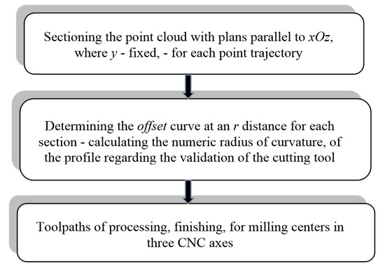
Figure 1.
Methodology for generating finishing toolpaths using ordered point cloud.
2.1. Ordered Point Cloud
Calculating the trajectories of finishing the processing is based on selecting a point cloud with plans parallel to xOz, for a fixed y. The matrix of points coordinates obtained ordered during scanning has growing values of the Ox respectively Oy axes. Knowing the values of the distances between the scanning trajectories, a sectioning plan was generated for each one of these, as follows:
For each y = yp = ymin + pΔy fixed we have, in a parallel plan with xOz, points from the matrix noted with
where,
Projected on the xOz plans, the points Pm determine a polygonal line (Figure 2) where,
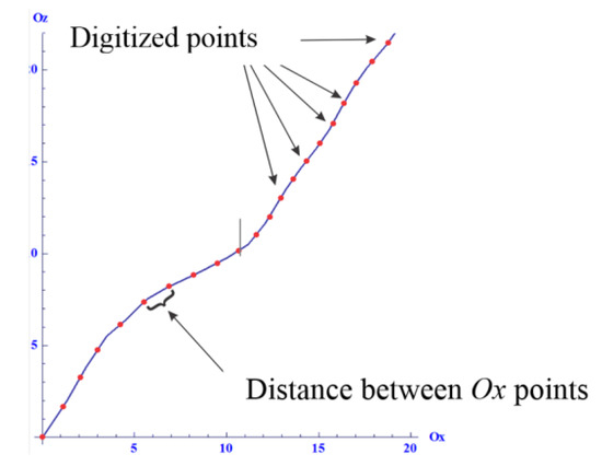
Figure 2.
The resulting profile curve based on the scanned points.
- p is a whole within 0 and the noted sections number;
- m has values from 1 to nps;
- nps is the number of points in the section.
For each segment [Pm, Pm+1], the equation in projection on the xOz plan is
The calculation and generation method were presented previously and were realized on the profile curve of the surface obtained by the points that form the cloud. The distance between the trajectories of finishing processing was made by the distance between the trajectory lines of the contact scanning process. For determining the finishing trajectories, it was chosen a sectioning with parallel plans with xOz for a fixed y. The distance between the finishing trajectories is given by the distance by the scanning lines. The matrix of the point coordinates, which was ordered and obtained at the scanning has growing values on the Ox respectively Oy axis.
The finishing methodology has been applied differently for the ordered point cloud versus the unordered one, as follows:
- Cloud segmentation: a section in the xOz plan was made where the y was fixed;
- The offset curve: based on the points belonging to each section, the results from the previous step was calculated for each individual offset curve on an r distance—the cutter radius based on the bend profile radius/c. The toolpath was obtained based on the offset curve, which contains the CL-cutter location point.
For each section at an r distance, representing the radius of the spherical milling type cutting tool, authors determined the offset curve of the resulted profile from digitized points for identifying the center of the milling cutter in order to generate the trajectory of the finishing processing. Figure 3 presents how to generate an offset curve using digitized data.
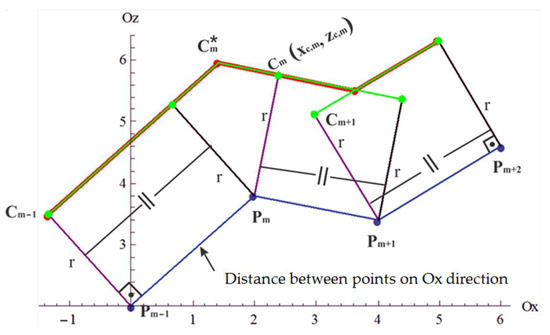
Figure 3.
Generating the offset curve.
Whereas the notations in the Figure 3, the curve were generated as following:
For were determined the points:
is located on a line perpendicular on the segment [Pm, Pm+1] at the r distance from this segment increasingly in the direction of the Oz axis.
The direct vector of the segment [Pm, Pm+1] was determined in the xOz plan, using:
The direct vector of the segment [Pm,Cm] has been calculated using formula:
and its length using formula:
The coordinates (xC,m, zC,m) are given by:
The offset point, corresponding to was calculated by intersecting the lines which pass through the points Cm−1 and Cm and have as direct vectors (Figure 4) , respectively , representing the solutions of the system.
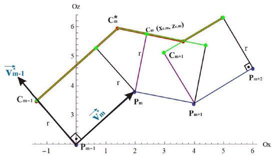
Figure 4.
Representing the direct vectors.
- if , then the points are not collinear
- if , then C*m = Cm
Condition—In this step a calculation was performed for each section plan, which numerically determines the radius. This calculation has the role to identify, whereas the diameter of the mill used to perform the technological finishing operation is concerned, the radius areas of the profile resulted by using the digitized points regarding the validation of the mill in order not to chip below the level of the profile curve of the complex surface. Using the general calculation formula for the radius of curvature, the calculation algorithm and generating the trajectories of the finishing operation, the derivatives were replaced with finite differences.
Thus, for a constant x and a fixed y, be the and K radius in the (xm, zm) point was calculated using the earlier mentioned equation, for calculating the radius, where , where m ≥ 2 and m ≤ . In the Pm point, for was calculated using the formula:
- if for then it leads to determining the offset curve, contrary, it resumes so the condition be verified for
The curve calculation presented above, in which y is fixed, was generated also in the case of the Oy direction. Thus, it could be elaborated within the calculation of the trajectory of the finishing processing for an ordered point cloud, by calculating the curve in the case x is fixed for validating the cutting mill and not affect the profile of the complex surface.
The calculation formula for a fixed x is:
2.2. Unordered Cloud Points
In case of the unordered cloud points, control points were established by using the following algorithm:
- Dividing the machined area into 0.2 mm side squares (Figure 5), the intersection of each of the squares’ diagonals was considered a control point for the Bezier curve.
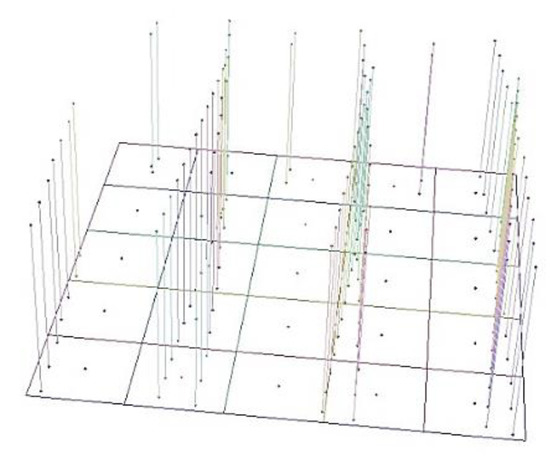 Figure 5. Dividing the machining area and establishing the center points.
 - It was verified that in the set of points within the square there is a point, which coincides with the intersection of the diagonals: if there is, it becomes a control point; if there is not, the Z coordinate of the intersection of the diagonals was determined using all the points belonging to the cloud point, which can be found in a 5 × 5 matrix centered on the square for which the z coordinate was determined.
In detailing the previous explanation, the finishing trajectories were generated by following the next steps:
- Filtering the point cloud: was made by using some rectangles, which contain the points of the cloud projected on the xOy plan. Generating the rectangles was performed starting at the reference point of the unordered point cloud, so the center of the first generated rectangle will coincide with the reference point. It was established within this stage that the distance between the centers of the rectangles be 0.1 mm on the Ox axis, and the value on the Oy axis between the processing trajectories be defined by the user.
- Establishing the points of the future path (trajectory): in the case of a rectangle there are no points belonging to the initial cloud, which can coincide with its center, so they were calculated according to other twenty five rectangles around it, using the arithmetic average of the values on the Z axis.
- The trajectory of the tool: based on the data previously obtained, identifying the points, which belong to the cloud and which coincide with the center of the rectangle was obtained an ordered point cloud above which will be applied the algorithm of the ordered point cloud.
Since the unordered point cloud is made from randomly displaced points, because of the multiple passes or invariable speed during the scanning process, it was opted for a processing of all the points within the unordered cloud. This processing was performed during the mathematical algorithm, with the help of some rectangles that contain the cloud points and were projected on the xOy plan. Generating the rectangles was performed starting from the reference point of the unordered cloud point, so that the center of the first generated rectangle will coincide with the reference point.
Processing complex surfaces on three-axis machine tools with CNC (Computer Numerical Control) implies using the cutting tools for spherical drill during the finishing process, due to their topology. Thus, it was established during this methodology that the distance between the centers of the rectangle be 0.1 mm on the Ox axis, and the value on the Oy axis between the processing trajectories be determined by the user. To perform the calculation of the points that belong to the external rectangles of the surface area, based on identifying the minimum and maximum points, a double approach was performed on the entire surface of the projected points. In this direction the value of each point on Z of the center belonging to each rectangle was calculated according to the other twenty-five rectangles around it, including it using the arithmetic average of the values on this axis.
There is a possibility that the center of a rectangle will not be any point of the cloud, which has a projection in the xOy plan. In this direction, to have points based on which will be generated finishing trajectories it was established a point that has a projection in the center of the rectangle using the conditions:
- The value on the Z axis was equal with the arithmetic average of the values on this axis of the points from the surrounding rectangles.
- The values corresponding to the X and Y axis will be the ones that define the respectively center of the rectangle.
3. Practical Validation of the Methodology
The technological process for the finishing processing was performed by using a mill tool of spherical geometrical shape due to the topology of the complex surface. The finishing trajectories (Figure 6) related to the finishing technological process and resulted on the grounds of the ordered cloud were generated by using the offset type of curve. Its calculation and generation method were presented earlier and was performed on the profile curve of the given surface through the composing points of the clouds.
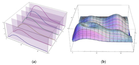
Figure 6.
(a) First six sectioning plans parallel with xOz and the projected points; (b) ordered finishing toolpaths.
The presented research in this paper shows the capability of the developed mathematical algorithms to generate finishing milling toolpaths for different type of digitized data input and different milling geometry cutters, as the ones shown in Figure 7, that can be used for different types of machining processes. It is to be mentioned that the end mill tool was used in the roughing milling process and the ball-nose geometry for the finishing milling process, Figure 8.

Figure 7.
Cutting milling tools used in the machining process.
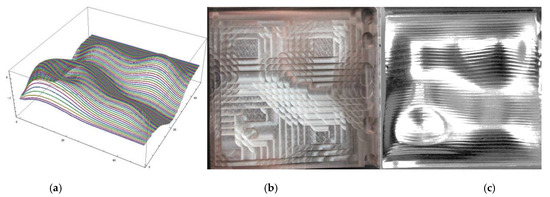
Figure 8.
Processing toolpaths (a) of an ordered point cloud, (b) roughed part and (c) the finished part.
Technical characteristics of the spherical milling and end milling tools and their performances that can be reached in the cutting process are given in Table 1.

Table 1.
Technical characteristics of the cutting milling tools used in the machining process.
According to the methodology, whereas the ordered point cloud is concerned, the distance between the trajectories of the finishing processing is given by the distance between the scanning trajectories. The algorithm resulted with the help of the mathematical tool will provide for each of these sectioning plans a color to easily identify the areas where the processing trajectories will be generated. After processing all the data and processing the 3 axis finishing milling toolpaths, Figure 8a and Figure 9a with the help of a software utility application of mathematics the NC files generated were transferred into the 3 Axis Vertical Milling Centre, Challenger 2418. Using this type of numerical control milling center were machined, Figure 8b roughing/Figure 8c finishing and Figure 9b roughing/Figure 9c finishing, the freeform complex surfaces parts based on the ordered and unordered input data.
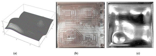
Figure 9.
Processing toolpaths (a) of an unordered point cloud, (b) roughed part and (c) the finished part.
In order to validate the proposed methodology, the machined surfaces of the parts by the milling cutting process were measured using the Werth ScopeCheck MB equipment. The comparative analysis result between generated surfaces using the algorithm presented in the current paper and the measured surfaces are shown in Figure 10 and Figure 11. In Figure 10 the analysis of the part obtained using non-contact, laser 3D scanning method (unordered point cloud) is presented and in Figure 11 the analysis of the part obtained using contact 3D scanning (ordered point cloud) method is presented. The differences between the values of accuracy obtained within the two analyses were caused by the total number of the constitutive points of digitized data. In the case of 3D contact scanning (ordered point cloud), there are a smaller number of points collected as compared to the 3D laser scanning (unordered point cloud) due to the fact when using 3D laser scanning there are no predefined scanning trajectories like in the case of 3D contact scanning.
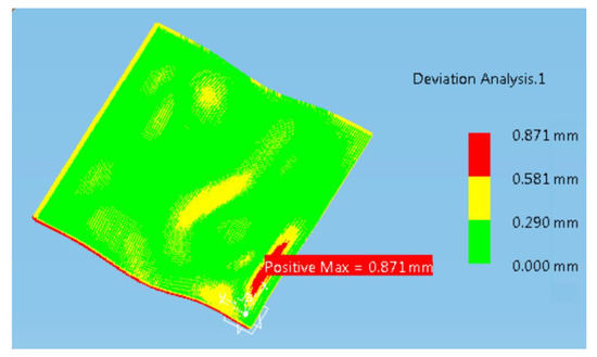
Figure 10.
Comparative analysis result between generated surface and the measured surface with non-contact, laser 3D scanning (unordered point cloud).
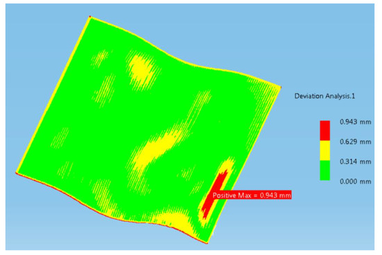
Figure 11.
Comparative analysis result between generated surface and the measured surface with contact 3D scanning (ordered point cloud).
By analyzing the obtained results, the large scale of the analyzed surface fits into an acceptable error scale reached there were in the admissible tolerance limits, the mathematical algorithm that was used for generating the paths of machining proving that the method developed by the authors was reliable for this type of machining process. Deviation analysis is the result of a manual overlapping of the measured data; it is not performed in an automated manner. In this sense, the deviation error it is to be considered the consequence of the manual overlapping of the data within the CAD analysis software.
The dimensional deviations appeared and presented in Figure 10 and Figure 11 are the consequence of using CAD software dedicated for validation of 3D scanned surfaces. It can be seen in Figure 10 and Figure 11 that on the fixing contour, the algorithm for interpreting the 3D scanned points of the CAD software presents a certain error due to manual overlap of the reference model and the one resulted through the one reached using the algorithm for generating the toolpaths for finishing milling operation developed within this paper.
4. Conclusions
The direct milling process using digitized data as input information instead of the 3D model, mesh or surface aims to generate toolpaths in order to eliminate the possible errors that appear in the CAD modeling phase as part of requirements engineering chain of processes. The finishing processing trajectories that were obtained, according to the methodology employed and described by the authors are the result of the offset curves obtained once the employed calculation algorithm was applied. In order to validate the theoretical aspects, the authors have used for practical validation a freeform surface of a master part that contains cusps and even a caldera and without snags due to three axis milling process on which the authors were focusing. Graphical representation of a complex surfaces through a 3D point cloud is the graph of a function of two variables, z = f (x,y). The construction of computing mathematical algorithms underlying theoretical model was performed by using a software utility application of mathematics, Mathematica Wolfram. The files containing the 3D ordered point cloud used within the authors proposed methodology was composed in 47,817 points, and the unordered point cloud files had 196,057 points. The numerical command file that was generated to complete the technological finishing operation was constructed using G commands corresponding to certain operations and auxiliary functions, and the M commands according to the ISO 6983 standard. According to the present work it was demonstrated that the entire work of the authors was eligible and relevant for the direct machining process of complex surfaces (machined on three axis NC machine tools). To expend the research as future work, the authors intend to use the presented methodology on a larger amount of digitized data. The present work describes the developing of mathematical algorithms in the context of milling toolpaths generation process using as support the information gathered from a wide use technique known as 3D scanning. The input data represents the physical part in the 3D virtual working space under the shape of a point cloud. The entire mathematical algorithms presented in the current research can be used, as demonstrated in practice, for two different input data of point cloud and also different milling cutting tools geometry. The novel element that current research highlights is represented by the fact that there is no limitation regarding the total constituent number of a point cloud, digitized data, even in the case when different tools geometry and dimensions are used in the cutting process.
Author Contributions
Conceptualization, F.P.; methodology, D.P.; software, F.P.; validation, D.P.; formal analysis, R.P.; investigation, F.P.; resources, D.P.; data curation, F.P.; writing—original draft preparation, F.P.; writing—review and editing, R.P. and A.P.; visualization, D.P.; supervision, D.P.; project administration, D.P.; funding acquisition, R.P. All authors have read and agreed to the published version of the manuscript.
Funding
This research was funded by the ERASMUS+ Strategic partnership program for Digital Education (KA226)—Boosting the scientific excellence and innovation capacity of 3D printing methods in pandemic period—BRIGHT—contract no. 2020-1-RO01-KA226-HE-095517.
Institutional Review Board Statement
Not applicable.
Informed Consent Statement
Not applicable.
Data Availability Statement
No new data were created or analyzed in this study. Data sharing is not applicable to this article.
Conflicts of Interest
The authors declare no conflict of interest.
References
- Helle, H.R.; Lemu, H.G. A case study on use of 3D scanning for reverse engineering and quality control. Mater. Today Proc. 2021, 45, 6. [Google Scholar] [CrossRef]
- Pang, T.Y.; Fard, M. Reverse Engineering and Topology Optimization for Weight-Reduction of a Bell-Crank. Appl. Sci. 2020, 10, 8568. [Google Scholar] [CrossRef]
- Herzog, B.; Osamah, S. Reverse Engineering of Option Pricing: An AI Application. Int. J. Financ. Stud. 2019, 7, 68. [Google Scholar] [CrossRef]
- Tashi; Ullah, A.S.; Kubo, A. Geometric Modeling and 3D Printing Using Recursively Generated Point Cloud. Math. Comput. Appl. 2019, 24, 83. [Google Scholar] [CrossRef]
- Vinesh, R.; Kiran, J.F. 2008 Reverse Engineering an Industrial Perspective; Springer: London, UK, 2008. [Google Scholar]
- Bradley, C.; Currie, B. Advances in the Field of Reverse Engineering. Comput. Aided Des. Appl. 2013, 2, 697–706. [Google Scholar] [CrossRef]
- Sang, C.P.; Yun, C.C. Tool-path generation from measured data. Comput. Aided Des. 2003, 35, 467–475. [Google Scholar]
- Wulle, F.; Richter, M.; Hinze, C.; Verl, A. Time-optimal Path Planning of Multi-axis CNC Processes Using Variability of Orientation. Procedia CIRP 2021, 96, 324–329. [Google Scholar] [CrossRef]
- Yu, B.-F.; Chen, J.-S. Development of an Analyzing and Tuning Methodology for the CNC Parameters Based on Machining Performance. Appl. Sci. 2020, 10, 2702. [Google Scholar] [CrossRef]
- Holub, M.; Jankovych, R.; Vetiska, J.; Sramek, J.; Blecha, P.; Smolik, J.; Heinrich, P. Experimental Study of the Volumetric Error Effect on the Resulting Working Accuracy—Roundness. Appl. Sci. 2020, 10, 6233. [Google Scholar] [CrossRef]
- Aberle, J.; Eikenberg, R.; Branß, T.; Henry, P.-Y. Technical Note: On the Production and Accuracy of CNC-Manufactured Hydraulic Scale Models. Water 2021, 13, 916. [Google Scholar] [CrossRef]
- Fitzpatrick, A.P.; Collins, P.K.; Gibson, I. 3D scan process optimisation study for rapid virtualization. Procedia CIRP 2020, 91, 911–916. [Google Scholar] [CrossRef]
- Dmengeon-Pedreiro-Balbino, F.; Aracélly-Reis-Medeiros, K.; Roberto-Hall-Barbosa, C. Comparative Analysis of Object Digitization Techniques Applied to the Characterization of Deformed Materials in Ballistic Tests. Sensors 2020, 20, 5017. [Google Scholar] [CrossRef] [PubMed]
- Lazarević, D.; Nedić, B.; Jović, S.; Šarkoćević, Ž.; Blagojević, M. Optical inspection of cutting parts by 3D scanning. Phys. A Stat. Mech. Appl. 2019, 531, 121583. [Google Scholar] [CrossRef]
- Fountas, N.A.; Vaxevanidis, N.M. Intelligent 3D tool path planning for optimized 3-axis sculptured surface CNC machining through digitized data evaluation and swarm-based evolutionary algorithms. Measurement 2020, 158, 107678. [Google Scholar] [CrossRef]
- Zheng, J.-D.; Zhang, L.-Y.; Du, X.-Y.; Ding, Z.-A. 3D curve structure reconstruction from a sparse set of unordered images. Comput. Ind. 2009, 60, 126–134. [Google Scholar]
- Feng, H.-Y.; Teng, Z. Iso-planar piecewise linear NC tool path generation from discrete measured data points. Comput. Des. 2005, 37, 55–64. [Google Scholar] [CrossRef]
- Che, J.; Zhang, Y.; Wang, H.; Liu, Y.; Du, M.; Ma, S.; Zhao, Y.; Suo, C. A novel method for analysing working performance of milling tools based on reverse engineering. J. Pet. Sci. Eng. 2021, 197, 107987. [Google Scholar] [CrossRef]
- Shi, Z.; Wang, T.; Lin, J. A simultaneous calibration technique of the extrinsic and turntable for struc-tured-light-sensor-integrated CNC system. Opt. Lasers Eng. 2021, 138, 106451. [Google Scholar] [CrossRef]
- Jaskólski, P.; Nadolny, K.; Kukiełka, K.; Kapłonek, W.; Pimenov, D.Y.; Sharma, S. Dimensional Analysis of Workpieces Ma-chined Using Prototype Machine Tool Integrating 3D Scanning, Milling Shaped Grinding. Materials 2020, 13, 5663. [Google Scholar] [CrossRef]
- Dong, Z.; Sun, X.; Liu, W.; Yang, H. Measurement of Free-Form Curved Surfaces Using Laser Triangulation. Sensors 2018, 18, 3527. [Google Scholar] [CrossRef]
- Daoshan, O.; Van Nest, A.B.; Feng, H.Y. Automatic Ball-End Milling Tool Selection from 3D Point Cloud Data. Flex. Autom. Intell. Manuf. FAIM 2004, 253–260. [Google Scholar]
- Lin, A.C.; Liu, H.T. Automatic generation of NC cutter path from massive data points. Comput. Aided Des. 1998, 30, 77–90. [Google Scholar] [CrossRef]
- Yin, Z. Adaptive tool path generation from measured data. Proc. Inst. Mech. Eng. Part. B J. Eng. Manuf. 2004, 218, 103–111. [Google Scholar] [CrossRef]
- Peng, Y.H.; Yin, Z.W. A new strategy for direct tool path generation from measured points. Int. J. Prod. Res. 2005, 43, 933–944. [Google Scholar] [CrossRef]
- Byoung, K.C.; Robert, B.J. Sculptured Surface Machining; Springer: Berlin/Heidelberg, Germany, 1999. [Google Scholar]
- Yau, H.T.; Hsu, C.Y. Generating NC tool paths from random scanned data using point-based models. Int. J. Adv. Manuf. Technol. 2009, 41, 897–907. [Google Scholar] [CrossRef]
- Stratogiannis, F.I.; Galanis, N.I.; Karkalos, N.E.; Markopoulos, A.P. Optimization of the Manufacturing Strategy, Machining Conditions, and Finishing of a Radial Impeller. Machines 2019, 8, 1. [Google Scholar] [CrossRef]
- Tuli, T.B.; Cesarini, A. Automated Unsupervised 3D Tool-Path Generation Using Stacked 2D Image Processing Technique. J. Manuf. Mater. Process. 2019, 3, 84. [Google Scholar] [CrossRef]
- Seokbae, S.; Hyunpung, P.; Kwan, H.L. Automated laser scanning system for reverse engineering and inspection. Int. J. Mach. Tools Manuf. 2002, 42, 889–897. [Google Scholar]
- Mohammad, G.; Mohammad, R.M. Extraction of surface curvatures from tool path data and prediction of cutting forces in the finish milling of sculptured surfaces. J. Manuf. Process. 2019, 45, 273–289. [Google Scholar] [CrossRef]
- Zou, Q.; Wang, C.C.L.; Feng, H.Y. Length-optimal tool path planning for freeform surfaces with preferred feed directions points. arXiv 2009, arXiv:2009.02660. [Google Scholar]
- Teng, Z.; Feng, H.Y.; Azeem, A. Generating efficient tool paths from point cloud data via machining area segmentation. Int. J. Adv. Manuf. Technol. 2006, 30, 254–260. [Google Scholar] [CrossRef]
- Feng, H.-Y.; Li, H. Constant scallop-height tool path generation for three-axis sculptured surface machining. Comput. Des. 2002, 34, 647–654. [Google Scholar] [CrossRef]
- Li, D.Y.; Peng, Y.H.; Yin, Z.W. Interference detection for direct tool path generation from measured data points. Eng. Comput. 2006, 22, 25–31. [Google Scholar] [CrossRef]
- Jung, T.-S.; Yang, M.-Y.; Lee, K.-J. A new approach to analysing machined surfaces by ball-end milling, part I. Int. J. Adv. Manuf. Technol. 2005, 25, 833–840. [Google Scholar] [CrossRef]
- Chui, K.L.; Yu, K.M.; Lee, T.C. Direct tool-path generation from massive point input. Proc. Inst. Mech. Eng. Part B J. Eng. Manuf. 2002, 216, 199–206. [Google Scholar] [CrossRef]
- Matras, A.; Zębala, W. Optimization of Cutting Data and Tool Inclination Angles During Hard Milling with CBN Tools, Based on Force Predictions and Surface Roughness Measurements. Materials 2020, 13, 1109. [Google Scholar] [CrossRef]
- Khisamutdinov, R.M.; Sungatov, I.Z.; Khisamutdinov, M.R. Kinematics of Spherical Milling Cutters Forming. Procedia Eng. 2017, 206, 1292–1297. [Google Scholar] [CrossRef]
- Neagu, C.; Lupeanu, M.; Rennie, A. A new design concept for milling tools of spherical surfaces obtained by kinematic generation. Appl. Math. Model. 2013, 37, 6119–6134. [Google Scholar] [CrossRef]
Publisher’s Note: MDPI stays neutral with regard to jurisdictional claims in published maps and institutional affiliations. |
© 2021 by the authors. Licensee MDPI, Basel, Switzerland. This article is an open access article distributed under the terms and conditions of the Creative Commons Attribution (CC BY) license (https://creativecommons.org/licenses/by/4.0/).