Abstract
This study investigates the design of fault-tolerant control involving adaptive nonsingular fast terminal sliding mode control and neural networks. Unlike those of previous control strategies, the adaptive law of the investigated algorithm is considered in both continuous and discontinuous terms, which means that any disturbances, model uncertainties, and actuator faults can be simultaneously compensated for. First, a quadcopter model is presented under the conditions of disturbances and uncertainties. Second, normal adaptive nonsingular fast terminal sliding mode control is utilized to handle these disturbances. Thereafter, fault-tolerant control based on adaptive nonsingular fast terminal sliding mode control and neural network approximation is presented, which can handle the actuator faults, model uncertainties, and disturbances. For each controller design, the Lyapunov function is applied to validate the robustness of the investigated method. Finally, the effectiveness of the investigated control approach is presented via comparative numerical examples under different fault conditions and uncertainties.
1. Introduction
In recent years, unmanned aerial vehicles (UAVs) have been commercialized widely in the market, due to technological developments in the fields of electronics, computers, and mechanics. They have been contributing significant achievements and benefits in different applications such as coastal surveillance, payload transportation, military and defense, and environmental monitoring. Quadcopter, a small UAV, has been investigated and improved for a wide range of applications due to its merits such as agility, mechanical simplicity, and both indoor and outdoor performances, which have rendered its popularity when compared to other kinds of UAV systems. Quadcopters have been studied and developed using different technologies, including object detection and tracking control, formation flight control, obstacle avoidance, remote sensing, and fault tolerant control.
The quadcopter system can be controlled using traditional and advanced control methods. Several classical control techniques have been employed to control [1,2] the quadcopter, such as proportional-integral-derivative (PID) controller and gain scheduling PID [3,4,5] controller. Many advanced control laws have been utilized to enhance the robustness of the quadcopter. In [6,7], a sliding mode control-based adaptive law has been presented to control the position and attitude of the quadcopter. In [8,9], an L1 adaptive control has been proposed to handle the model uncertainties and time delay. Neural network PID and fuzzy control methods [10,11,12,13] have also been investigated for utilization in the quadcopter’s flight controller.
Normally, the quadcopter is exploited to operate in a sophisticated and hazardous environment. Due to the lack of redundant systems, actuator failures have a high impact on the reliability and safety of a quadcopter. To use quadcopters in widespread applications, it is important to improve its reliability. This stimulates the study of fault diagnosis (FD) and fault tolerant control (FTC) to enhance the reliability of the use of UAVs. The FD strategy serves to detect and estimate faults, whereas the FTC is designed to deal with the unexpected system behaviors induced by various failures. FTC methods can normally be divided into two groups: active FTC (AFTC) scheme and passive FTC (PFTC) scheme. In the AFTC system, the FD observer design must reconfigure a nominal controller. On the other hand, the PFTC system provides a quicker fault compensation without using any information feedback from an FD unit. However, the PFTC system has a limited tolerance to fault effects because there is no FD information. Therefore, a robust controller must be designed in this PFTC system. Several robust control methods have been investigated for quadcopter systems, such as neural networks [14,15], fuzzy control [16,17], adaptive sliding mode control [18,19], model predictive control [20,21], and sliding mode control (SMC) [22,23]. When compared to other methods, SMC has been presented as a robust and exceptional method to address matched uncertainties through a sliding surface. The special advantages of SMC have been employed significantly to design robust control systems [24,25]. According to the general principle design of traditional SMC, a continuous or discontinuous control part is used under the assumption that the uncertainties of the system are upper bounded. The insensitivity to disturbances and parametric uncertainties makes SMC one of the most promising methods [26]. However, this method has the limitation of oscillation (chattering phenomenon) because of the large gain obtained during the discontinuous term, which requires extra deliberation during the experiment. Moreover, it is difficult to obtain the upper bound value of uncertainties for this control system. In general, SMC is integrated with other control methods and adaptive laws to handle both chattering and upper-bound value problems. However, the conventional SMC approaches do not converge in a finite time in the concept of linear sliding mode, which stimulates the use of a nonlinear sliding mode surface for control systems. In [27,28], with the proposed terminal SMC (TSMC) method, system states can converge to the equilibrium point in a finite amount of time. However, this method has a slower convergence when compared to conventional SMC, and it has singularity issues. To overcome the problem of slow convergence and singularity, nonsingular TSMC (NTSMC) [29,30] and nonsingular fast TSMC (NFTSMC) [31,32] were investigated. Although NTSMC and NFTSMC have the same nonsingular characteristics, NFTSMC provides a faster convergence than NTSMC. When the system states are far away from the equilibrium, they can move quickly to the sliding surface.
In this paper, a fault-tolerant control method based on NFTSMC has been proposed. To highlight the proposed algorithm, the adaptive NFTSMC (ANFTSMC) has first been proposed. Then, its drawback is discussed. Considering the drawback, ANFTSMC based on neural networks and adaptive algorithms was analyzed. In this strategy, while ANFTSMC is used to tackle bounded disturbances, neural networks and adaptive laws are proposed to handle the uncertainties that might occur during both discontinuous and continuous terms. The major contributions of this article can be summarized as follows:
- The NFTSMC method is used to enhance the convergence speed and robustness of the quadcopter system.
- The adaptive law is integrated with the NFTSMC to tackle the unknown external disturbances.
- Radial basic function neural networks (RBFNNs) are combined with adaptive laws to handle model uncertainties and actuator faults.
- The proposed control technique has several merits such as robustness, fast finite time convergence, handling model uncertainties and external disturbances, accommodating actuator faults, and lack of magnitude information of bounded faults.
The remainder of this paper is organized as follows. The problem formulation of the quadcopter system is presented in Section 2. Section 3 describes the design of the flight controller. Three types of control techniques are compared to show the robustness and effectiveness of the proposed controller through simulation results in Section 4. Section 5 presents the conclusions and future work.
2. Problem Formulation
2.1. Mathematical Tools
In this study, RBFNNs were employed to approximate the model uncertainties and actuator faults. The approximation algorithm is shown in [33] as,
In Equation (1), the optimal weight is denoted as , the hidden node number is expressed as , the input vector is given as , and , is the approximation error that meets the requirement of with an unknown constant given as . The optimal weight is denoted as the value of that minimizes for , that is,
The Gaussian function is defined as follows:
where is the center of the receptive field, and is the width of the Gaussian function.
2.2. Nonsingular Fast Terminal Sliding Mode
The nonsingular fast terminal sliding mode (NFTSM) method was employed to improve the robustness of the quadcopter during actuator faults, external disturbances, and model uncertainties. The NFTSM surface is defined as [32],
In Equation (4), the position and velocity tracking errors are denoted as , and , respectively. and are the odd positive numbers and these satisfy the requirements of and , respectively. and are the positive constants. The first derivative of Equation (4) can be expressed as,
Lemma 1.
If the sliding surface, the moving point will reach the sliding surface. At this point, the system changes from the motion mode to the sliding mode. If the convergence timeis determined using the following equation: , then, the finite timeofis obtained as
whereis the initial value of, andrepresents the Gauss’ hypergeometric function.
2.3. Quadcopter Model
Figure 1 illustrates the configuration of a quadcopter. Four propellers are mounted on the corresponding motors in a cross configuration. While the motors and spin in the clockwise direction, the other motors ( and ) spin in the counter-clockwise direction. The forces generated by the motors are represented as and the corresponding angular velocities produced by the motors are denoted as .
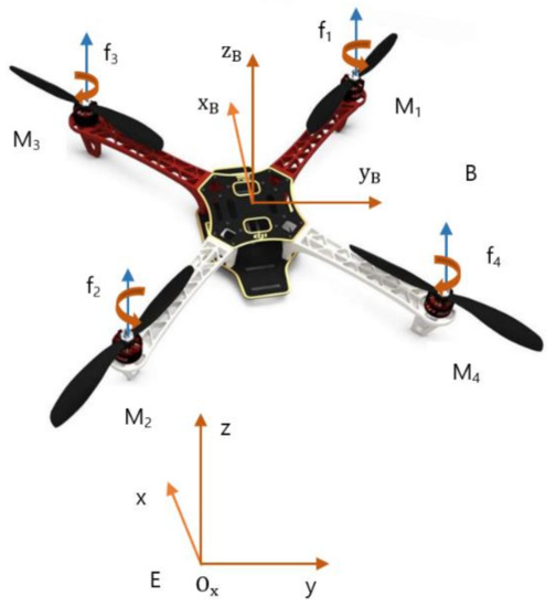
Figure 1.
Quadcopter model.
Two coordinate systems were employed to represent the model of the quadcopter system. The earth-fixed frame axes are described as , and the body-fixed frame axes are denoted as . As depicted in Figure 1, the total thrust in the - direction is described as . The torque in the -direction is generated by the difference between two left and two right propellers, and is defined as . The pitch moment in the -direction is produced by the difference between two front and two rear propellers and is denoted by . The torque in the -direction is the difference between two counter-clockwise and two clockwise propellers, and is defined as . The relation between the control input and output can be expressed as
where and are the thrust and drag coefficient, respectively, is the arm length, which is the distance from the center of mass to each propeller.
According to the Newton–Euler law, the dynamical model of the quadcopter can be expressed as [6],
In Equation (8), is the gravitational acceleration constant and is the total mass of the quadcopter. The inertial moments in and directions are , and , respectively. The global position of the quadcopter is denoted as . The drag coefficients are represented as The roll, pitch, and yaw angles are denoted as , and , respectively. The disturbances are denoted as .
Let us define the state vector as,
The general model of the quadcopter under an actuator fault is expressed as
where denotes each subsystem, , , , , and is the actuator fault effectiveness with .
3. Flight Controller Design
In this section, we consider two scenarios of controller design. Firstly, an adaptive NFTSM control (ANFTSMC) method has been presented to handle bounded disturbances. Secondly, the ANFTSMC is integrated with a neural network to handle the actuator faults, disturbances, and model uncertainties.
3.1. Design of ANFTSMC
Assumption 1.
The disturbance in the quadcopter model (10) is norm-bounded with the requirement.
In case of , let us define the first and second tracking errors as
where is the virtual control, is a constant, and is the desired state.
The first derivative of is
Similarly, the first derivative of is:
As per Section 2.2, the design of ANFTSMC for quadcopter can be achieved as,
The first derivative of Equation (14) is given by the following equation:
The Lyapunov function is chosen as follows:
where , and is the estimate of .
The first derivative of is expressed as,
By means of defining and , the control law can be designed as,
where
and the adaptive law is updated by the following equation:
where is the positive gain.
Theorem 1.
Consider the general model of the quadcopter shown in Equation (10), and the sliding surface in Equation (14). If the controller defined in Equation (18) is updated by Equation (21), then the system converges to the sliding surface within a finite time.
Proof.
After inserting Equations (18)–(21) into Equation (17), we have:
Let us define . From Assumption 1, we can obtain
According to the Lyapunov theory, the system states converge to the sliding surface asymptotically.
Remark 1.
In this controller design, the adaptive law in discontinuous term is considered in presence of disturbances. To enhance the robustness of the system in presence of disturbances, uncertainties, and actuator faults, the adaptive law can be designed in both continuous and discontinuous term.
3.2. Synthetizing ANFTSMC with Neural Network
In this section, the ANFTSMC is combined with neural network to handle three tasks, including disturbances, actuator faults, and uncertainties. Then, the stability of whole system is verified through the Lyapunov function.
Let and , where is the estimate of .
Theorem 2.
Consider the actuator fault, disturbances, and model uncertainties occurring in the system (Equation (10)). Let the following neural network-based fault tolerant control (NNFTC) be implemented as,
and updated as:
whereare the positive gains. Then, the closed-loop system becomes stable, and it will reach the sliding mode within a finite time.
Proof.
As per Section 2.2, the sliding surface can be chosen as,
The first derivative of Equation (28) is expressed as,
The Lyapunov function is chosen as,
The first derivative of the Lyapunov function is expressed as,
Replacing Equations (24)–(27) and (29) into (31), we have
If we assume that , then the system states converge to the sliding surface asymptotically according to the Lyapunov theory.
4. Simulation
Some simulations are presented to demonstrate the effectiveness of the proposed FTC (PFTC) from Section 3.2. To highlight the effectiveness and robustness of the PFTC, conventional SMC [34] and adaptive sliding mode control (ASMC) [6] were chosen for comparison. The complete parameters of the quadcopter model are described in Table 1.

Table 1.
Parameters of the quadcopter model.
The parameters for the proposed controller can be designed as , 0.5, . Three scenarios are illustrated to validate the robustness and effectiveness of the proposed control method. In Scenario 1, multiple faults are investigated without considering uncertainties and disturbances. In Scenario 2, in addition to multiple faults, uncertainties and disturbances are added in Scenario 1 to consider the effectiveness and robustness of the developed control method. In Scenario 3, the intermittent fault is injected into one actuator by considering the uncertainties and disturbances to demonstrate the superiority of the proposed method.
4.1. Scenario 1
In this scheme, faults are injected into actuators #4 and #3 under 20% and 25% loss of control effectiveness (LoCE) at 22 s and 52 s, respectively. The attitude tracking and attitude tracking errors without considering uncertainties and disturbances are depicted in Figure 2 and Figure 3. After faults occur in actuators #4 and #3, the PSMC can compensate for these faults perfectly to maintain the attitude tracking performance, and the attitude tracking errors converge quickly to zero. Although ASMC shows a small oscillation after the occurrence of such faults, the feedback attitude angles can gradually track the desired attitude angles. The SMC showed the worst attitude tracking response after faults occurred. The motor inputs of the quadcopter are depicted in Figure 4. After faults occur, the motor inputs in actuators #4 and #3 are increased to accommodate these faults. The PSMC contributes more control efforts than ASMC and SMC because of the adaptive gain in the discontinuous part.
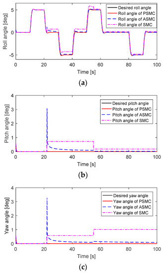
Figure 2.
Attitude tracking performance without considering any uncertainties and disturbances: (a) Roll angle; (b) Pitch angle; (c) Yaw angle.
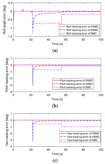
Figure 3.
Attitude tracking error performance without considering any uncertainties and disturbances: (a) Roll tracking error; (b) Pitch tracking error; (c) Yaw tracking error.
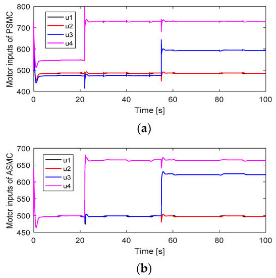
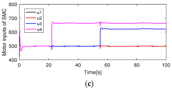
Figure 4.
Motor inputs: (a) Motor inputs of PSMC; (b) Motor inputs of ASMC; (c) Motor inputs of SMC.
4.2. Scenario 2
In this scenario, in addition to the multiple faults presented in Scenario 1, a 10% mismatch in the moment of inertia and disturbances () was examined. Figure 5 and Figure 6 depict the attitude tracking and attitude tracking errors by considering uncertainties and disturbances.
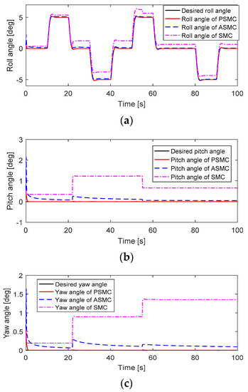
Figure 5.
Attitude tracking performance without considering any uncertainties and disturbances: (a) Roll angle; (b) Pitch angle; (c) Yaw angle.
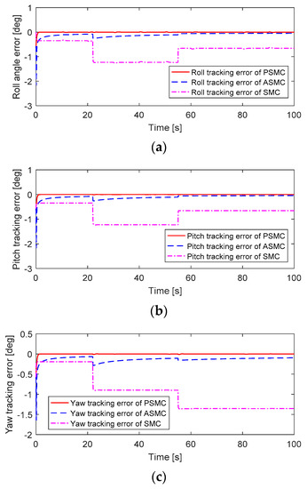
Figure 6.
Attitude tracking error performance without considering any uncertainties and disturbances: (a) Roll tracking error; (b) Pitch tracking error; (c) Yaw tracking error.
When faults occur in actuators #4 and #3, the PSMC can compensate for these faults perfectly to maintain the attitude tracking performance, and the attitude tracking errors converge quickly to zero. Although ASMC shows a small oscillation after the occurrence of these faults, the feedback attitude angles can gradually track the desired attitude angles. The SMC showed the worst attitude tracking response after faults occurred. The motor inputs of the quadcopter are depicted in Figure 7. After faults occur, the motor inputs in actuators #4 and #3 were increased to accommodate these faults. The PSMC contributes more control efforts than ASMC and SMC because of the adaptive gain in the discontinuous part.
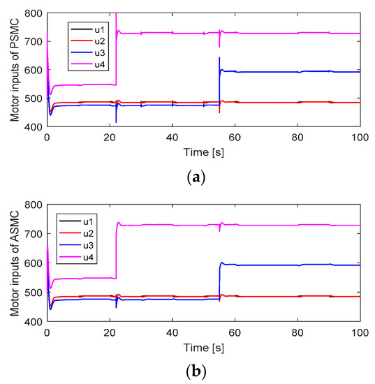
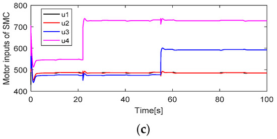
Figure 7.
Motor inputs: (a) Motor inputs of ASMC; (b) Motor inputs of SMC.
4.3. Scenario 3
In this scenario, a 40% LoCE is applied to actuator #4 with the following function scheme:
where is the old motor input, and is the new motor input.
A 10% mismatch in the moment of inertia and disturbances () was examined. Attitude tracking and tracking error performances are depicted in Figure 8 and Figure 9. It can be seen that after intermittent faults occur in actuator #4, the PSMC can accommodate these faults to maintain the trajectory tracking performance, and the attitude tracking errors converge to zero quickly. The ASMC shows a slow compensation in the presence of uncertainties and intermittent faults. The motor inputs of the quadcopter are depicted in Figure 10. After faults occur, the motor inputs in actuator #4 are increased to compensate for these faults. The PSMC contributes more control efforts than ASMC because of the adaptive gain in the discontinuous part.
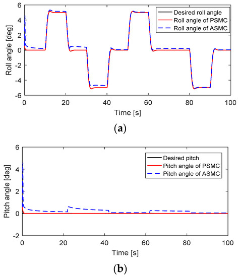
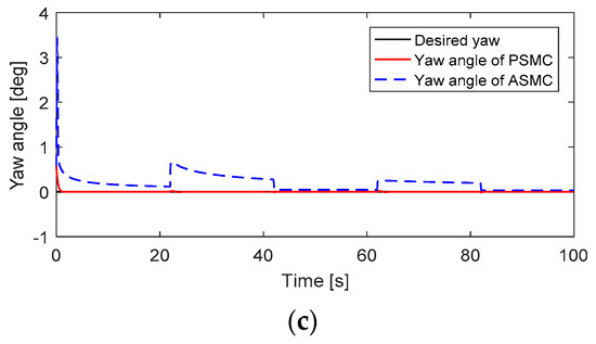
Figure 8.
Attitude tracking performance: (a) Roll angle; (b) Pitch angle; (c) Yaw angle.
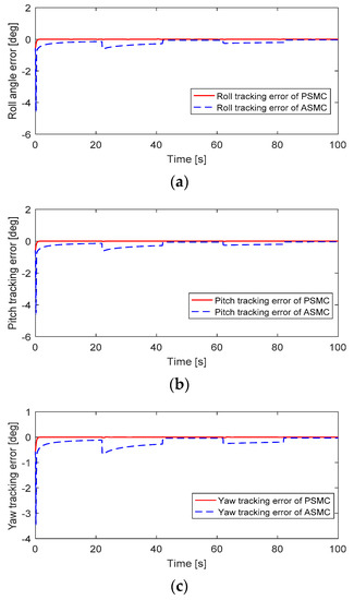
Figure 9.
Attitude tracking errors: (a) Roll tracking error; (b) Pitch tracking error; (c) Yaw tracking error.
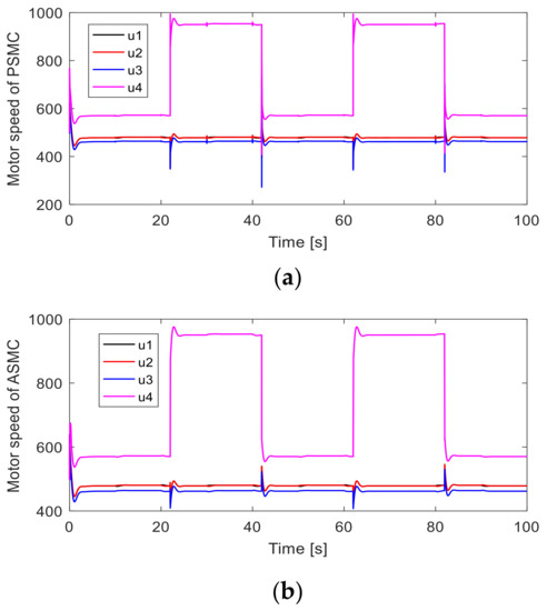
Figure 10.
Motor inputs: (a) Motor inputs of PSMC; (b) Motor inputs of ASMC.
Remark 2.
This article mainly focuses on partial loss effectiveness in single or multiple actuators. Therefore, the complete fault in one actuator (one motor is failure) is not considered in this work due to the scope of this paper. However, to overcome this issue, the configuration technique of allocation matrix [35] is applied to guarantee the stability of the quadcopter system.
5. Conclusions
In this study, an attitude fault-tolerant control based on a nonsingular fast terminal sliding mode and a neural network have been proposed for a quadcopter. The developed method not only can guarantee the robustness but also can enhance the convergence speed of the attitude tracking system within a finite time. To be more specific, the actuator faults, uncertainties, and bounded disturbances are compensated for through two schemes. Firstly, the ANFTSMC is designed to handle the bounded disturbances without considering the actuator faults and uncertainties. Then, the ANFTSMC is integrated with neural networks to handle three targets, including uncertainties, disturbances, and actuator faults. The proposed control technique is compared with the adaptive sliding mode control and normal sliding mode control methods through three scenarios: (1) faults occur in actuator four and three without considering uncertainties and disturbances, (2) faults occur in actuator four and three with considering uncertainties and disturbances, (3) intermittent fault in actuator four with considering uncertainties and disturbances. The results indicate that the proposed control law is more robust than the other two methods in the presence of actuator faults, model uncertainties, and bounded disturbances. However, the proposed control method does not consider the time-varying disturbances and complete fault in one actuator. In future studies, the complete fault in one actuator, the implementation of the proposed control method on embedded system, and time-varying disturbances will be examined for a flight controller.
Author Contributions
Conceptualization, N.P.N. and S.K.; Methodology, N.P.N.; Software, N.P.N.; Validation, N.P.N.; Formal Analysis, N.P.N.; Investigation, N.P.N.; Resources, N.P.N.; Data Curation, N.P.N.; Writing—Original Draft Preparation, N.P.N.; Writing—Review and Editing, N.P.N., L.N.N.T.H., N.X.M., T.T.H.; Visualization, N.P.N.; Supervision, S.K.H.; Project Administration, S.K.H.; Funding Acquisition, S.K. All authors have read and agreed to the published version of the manuscript.
Funding
This research was funded by the MSIT(Ministry of Science and ICT), Korea, under the ITRC (Information Technology Research Center) support program(IITP-2020-2018-0-01423) supervised by the IITP (Institute for Information & communications Technology Promotion).
Acknowledgments
This research was supported by Guidance, Navigation, and Control Lab at Sejong University.
Conflicts of Interest
The authors declare no conflict of interest.
References
- Roger, M.-C.; Luis, T.A. Robust PID control of quadrotors with power reduction analysis. ISA Trans. 2020, 98, 47–62. [Google Scholar]
- Ragusa, R.; Corsaro, L.S.; Frazzetto, E.; Bertino, E.; Bellia, M.A.; Bertino, G. Hepatitis C Virus Infection in Children and Pregnant Woman.: An Updated Review of the Literature on Screening and Treatments. AJP Rep. 2020, 10, 121–127. [Google Scholar]
- Pounds, P.E.I.; Bersak, D.R.; Dollar, A.M. Stability of small-scale UAV helicopters and quadrotors with added payload mass under PID control. Auton. Robot. 2012, 33, 129–142. [Google Scholar] [CrossRef]
- Qiao, J.; Liu, Z.; Zhang, Y.M. Gain scheduling PID control of quad-rotor helicopter. In Proceedings of the 2019 IEEE International Conference on Unmanned Systems, Beijing, China, 27–29 October 2017. [Google Scholar]
- Gautam, D.; Ha, C. Control of a quadrotor using smart self-tuning fuzzy PID controller. Int. J. Adv. Robot. Syst. 2013, 10. [Google Scholar] [CrossRef]
- Nadda, S.; Swarup, A. On adaptive sliding mode control for improved quadrotor tracking. J. Vib. Control 2018, 24, 3219–3230. [Google Scholar] [CrossRef]
- Jia, Z.; Yu, J.; Mei, Y.; Chen, Y.; Shen, Y.; Ai, X. Integral backstepping sliding mode control for quadrotor helicopter under external uncertain disturbances. Aerosp. Sci. Technol. 2017, 68, 299–307. [Google Scholar] [CrossRef]
- Beikzadeh, H.; Liu, G. Trajectory tracking of quadrotor flying manipulators using L1 adaptive control. J. Frankl. Inst. 2018, 335, 6239–6261. [Google Scholar] [CrossRef]
- Suárez Fernández, R.A.; Dominguez, S.; Campoy, P. L1 adaptive control for Wind gust rejection in quad-rotor UAV wind turbine inspection. In Proceedings of the 2017 International Conference on Unmanned Aircraft Systems (ICUAS), Miami, FL, USA, 13–16 June 2017. [Google Scholar]
- Xu, Q.; Wang, Z.; Zhen, Z. Adaptive neural network finite time control for quadrotor UAV with unknown input saturation. Nonlinear Dyn. 2019, 98, 1973–1998. [Google Scholar] [CrossRef]
- Doukhi, O.; Lee, D.J. Neural network-based robust adaptive certainty equivalent controller for quadrotor UAV with unknown disturbances. Int. J. Control Autom. Syst. 2019, 17, 2365–2374. [Google Scholar] [CrossRef]
- Kayacan, E.; Maslim, R. Type-2 Fuzzy Logic Trajectory Tracking Control of Quadrotor VTOL Aircraft with Elliptic Membership Functions. IEEE/ASME Trans. Mechatron. 2017, 22, 339–348. [Google Scholar] [CrossRef]
- Bacik, J.; Durovsky, F.; Fedor, P.; Perdukova, D. Autonomous flying with quadrocopter using fuzzy control and ArUco markers. Intell. Serv. Robot. 2017, 10, 185–194. [Google Scholar] [CrossRef]
- Fei, J.; Ding, H. Adaptive sliding mode control of dynamic system using RBF neural network. Nonlinear Dyn. 2012, 70, 1563–1573. [Google Scholar] [CrossRef]
- Nicol, C.; Macnab, C.J.B.; Ramirez-Serrano, A. Robust neural network control of a quadrotor helicopter. In Proceedings of the Canadian Conference on Electrical and Computer Engineering, Niagara Falls, ON, Canada, 4–7 May 2008. [Google Scholar]
- Barghandan, S.; Badamchizadeh, M.A.M.; Jahed-Motlagh, R. Improved adaptive fuzzy sliding modecontroller for robust fault tolerant of a quadrotor. Int. J. Control Autom. Syst. 2017, 15, 427–441. [Google Scholar] [CrossRef]
- Zeghlache, S.; Djerioui, A.; Benyettou, L.; Benslimane, T.; Mekki, H.; Bouguerra, A. Fault tolerant control for modified quadrotor via adaptive type-2 fuzzy backstepping subject to actuator faults. ISA Trans. 2019, 95, 330–345. [Google Scholar] [CrossRef] [PubMed]
- Wang, B.; Zhang, Y. Adaptive sliding mode fault-tolerant control for an unmanned aerial vehicle. Unmanned Syst. 2017, 5, 209–221. [Google Scholar] [CrossRef]
- Nguyen, N.P.; Hong, S.K. Fault-tolerant control of quadcopter UAVs using robust adaptive sliding mode approach. Energies 2018, 12, 95. [Google Scholar] [CrossRef]
- Yu, B.; Zhang, Y.; Minchala, I.; Qu, Y. Fault-tolerant control with linear quadratic and model predictive control techniques against actuator faults in a quadrotor UAV. In Proceedings of the 2013 Conference on Control and Fault-Tolerant System, Nice, France, 9–11 October 2013. [Google Scholar]
- Alexis, K.; Nikolakopoulos, G.; Tzes, A. Model predictive quadrotor control: Attitude, altitude and position experimental studies. IET Control Theory Appl. 2012, 6, 1812–1827. [Google Scholar] [CrossRef]
- Merheb, A.; Noura, H.; Bateman, F. Design of passive fault-tolerant controllers of a quadrotor based on sliding mode theory. Int. J. Appl. Math. Comput. Sci. 2015, 25, 561–576. [Google Scholar] [CrossRef]
- Li, T.; Zhang, Y.; Gordon, B.W. Nonlinear fault-tolerant control of a quadrotor UAV based on sliding mode control technique. In Proceedings of the 8th IFAC Symsosium on Fault Detection, Supervision and Safety of Technical Processes, Mexico City, Mexico, 29–31 August 2012. [Google Scholar]
- Wang, B.; Zhang, Y. An adaptive fault-tolerant sliding mode control allocation scheme for multirotor helicopter subject to simultaneous actuator faults. IEEE Trans. Ind. Electron. 2018, 65, 4227–4236. [Google Scholar] [CrossRef]
- Zhang, D.; Liu, G.; Zhou, H.; Zhao, W. Adaptive sliding mode fault-tolerant coordination control for four-wheel independently driven electric vehicles. IEEE Trans. Ind. Electron. 2018, 65, 9090–9100. [Google Scholar] [CrossRef]
- Li, S.; Li, B.; Geng, Q. Adaptive sliding mode control for quadrotor helicopters. In Proceedings of the 33rd Chinese Control Conference, Nanjing, China, 28–30 July 2014. [Google Scholar]
- Venkataraman, S.T.; Gulati, S. Control of nonlinear systems using terminal sliding mode. In Proceedings of the 1992 American Control Conference, Chicago, IL, USA, 24–26 June 1992. [Google Scholar]
- Liang, Y.W.; Xu, S.D.; Tsai, C.L. Study of VSC reliable designs with application to spacecraft attitude stabilization. IEEE Trans. Control Syst. Technol. 2007, 15, 332–338. [Google Scholar] [CrossRef]
- Feng, Y.; Yu, X.; Man, Z. Non-singular terminal sliding mode control of rigid manipulators. Automatica 2002, 38, 2159–2167. [Google Scholar] [CrossRef]
- Aghababa, M.P. Finite-time chaos control and synchronization of fractional-order nonautonomous chaotic (hyperchaotic) systems using fractional nonsingular terminal sliding mode technique. Nonlinear Dyn. 2012, 1, 247–261. [Google Scholar] [CrossRef]
- Xu, S.S.D.; Chen, C.C.; Wu, Z.L. Study of nonsingular fast terminal sliding-mode fault-tolerant control. IEEE Trans. Ind. Electron. 2015, 62, 3906–3913. [Google Scholar] [CrossRef]
- Yang, L.; Yang, J. Nonsingular fast terminal sliding-mode control for nonlinear dynamical systems. Int. J. Robust Nonlinear Control 2011, 44, 401–415. [Google Scholar] [CrossRef]
- Wang, Z.; Shen, Y.; Zhang, X. Actuator fault estimation for a class of nonlinear descriptor systems. Int. J. Syst. Sci. 2014, 45, 487–496. [Google Scholar] [CrossRef]
- Sharafi, F.; Mirzaei, M.; Gordon, B.W.; Zhang, Y. Fault tolerant control of a quadrotor UAV using sliding mode control. In Proceedings of the 2010 Conference on Control and Fault-Tolerant System, Nice, France, 6–8 October 2010. [Google Scholar]
- Freddi, A.; Lanzon, A.; Longhi, S. A feedback linearization approach to fault tolerance in quadrotor vehicles. In Proceeding of the 18th World Congress the International Federation of Automatic Control, Milano, Italy, 28 August–2 September 2011. [Google Scholar]
© 2020 by the authors. Licensee MDPI, Basel, Switzerland. This article is an open access article distributed under the terms and conditions of the Creative Commons Attribution (CC BY) license (http://creativecommons.org/licenses/by/4.0/).