Article

Numerical Estimation of Switched Reluctance Motor Excitation Parameters Based on a Simplified Structure Average Torque Control Strategy for Electric Vehicles

1
Electrical Engineering Department, Mansoura University, Mansoura 35516, Egypt
2
Department of Electric Power Engineering, Budapest University of Technology and Economics, H-1521 Budapest, Hungary
3
Department of Automated Electrical Systems, Ural Power Engineering Institute, Ural Federal University, 620002 Yekaterinburg, Russia
4
College of Engineering at Wadi Addawaser, Prince Sattam Bin Abdulaziz University, Wadi Aldawaser 11991, Saudi Arabia
5
Electrical Engineering Department, Faculty of Engineering, Minia University, Minia 61111, Egypt
6
Electrical Engineering Department, Kafrelshiekh University, Kafr El-Sheikh 33511, Egypt
7
Department of Electromechanical, Systems and Metal Engineering, Ghent University, 9000 Ghent, Belgium
8
FlandersMake@UGent–corelab EEDT-MP, 3001 Leuven, Belgium
*
Author to whom correspondence should be addressed.
Mathematics 2020, 8(8), 1213; https://doi.org/10.3390/math8081213
Submission received: 1 July 2020 / Revised: 17 July 2020 / Accepted: 21 July 2020 / Published: 23 July 2020

Abstract

:
Switched reluctance motors (SRMs) have been receiving great attention in electric vehicle (EV) applications. However, the complicated control and inherent torque ripples are the major drawbacks of SRMs. This paper introduces a numerical estimation method for the optimum control parameters of SRM based on a simplified average torque control (ATC) strategy for EVs. The proposed control aims to simplify the control algorithm to cut down complexity and cost. Besides, it aims to achieve all the vehicle requirements. A multi-objective optimization problem is set to determine the most efficient excitation parameters that can fulfill the vehicle requirements. The objective function has two terms: torque ripple and efficiency. Proper constraints for both turn-on and turn-off angles are included in order to achieve high-performance control, maximum torque per Ampere (MTPA) production, and reliable operation. Besides, additional toque constraints are involved to ensure fast dynamics, high-performance torque tracking capability, and parameter insensitivity. The motor model is accurately achieved based on the experimentally measured torque and flux characteristics. Several simulations are executed to prove the feasibility and effectiveness of the proposed control. Moreover, experimental results are obtained to validate the theoretical findings. It is observed that the proposed control has a significant reduction of torque ripples compared to the conventional control methods. The average reduction ratio of torque ripple over the speed range is about 72.43%. Besides, the proposed control succeeds in maintaining a very good efficiency and high torque/current ratio. It also has a fast-dynamic performance.

1. Introduction

Thanks to their advantages in terms of structure, cost, reliability, efficiency, and fault-tolerance, switched reluctance motors (SRMs) have been receiving great attention in numerous industrial applications, including electric vehicles (EVs) [1,2,3,4]. However, the inherent double saliency structure makes the magnetic characteristics highly nonlinear. This, in turn, makes the control of SRM drives a complicated task. Besides, it results in a high torque ripple and vibration [5,6,7,8,9].
The torque control techniques of SRMs involve instantaneous torque control (ITC) and average torque control (ATC) [10,11,12]. Although ITC has a good capability of torque ripple reduction, it is meant only for limited speed ranges with a lower torque per ampere ratio [10]. Besides, it possesses a complicated control algorithm. ATC has many advantages compared to ITC. ATC possesses a simple structure, has no torque inverse models or torque sharing functions and offers higher torque/ampere ratios, as it has no current profiling for torque control. ATC requires only a discrete rotor position to estimate the maximum and minimum inductances. On the contrary, ITC needs a high-resolution feedback position signal to adjust the motor current at each sample time. ATC is suitable for the entire speed ranges, while ITC has a limited speed range, depending on the back-emf voltage. Despite the numerous advantages of ATC, it has higher torque ripples than ITC, but these ripples can be efficiently filtered by the vehicles’ inertia. Therefore, ATC is an advantageous solution for EVs [10,11,12,13].
In ATC, the main control parameters are the turn-on angle (θon), the turn-off angle (θoff), and the reference current (iref). The system performance depends on the estimation of these control parameters in accordance with the motor speed and load torque [10,13]. The current is controlled as a square waveform, and therefore only the θon and θoff angles are adjusted for the commanded reference torque. The on-line and off-line optimization of the θon and θoff angles for ATC is achieved mainly for torque ripple reduction, efficiency improvement, or copper loss minimization. Obtaining the optimal values of the θon and θoff angles could be done by analytical or numerical methods [14]. In [15], an on-line efficiency optimization scheme is presented. The θon and θoff angles are computed on-line using analytical formulations. The initial selection of angles is fine-tuned in steady-state operation to minimize the input power of the drive. This method is not suited for traction drives due to the continuous changing of the operating point. In [16], a predictive strategy is used for the optimization of the generated torque of the SRM drive. Although it involves a low implementation cost, as it uses analytical solutions for the θon and θoff angles, it assumes linear inductance profiles that affect the accuracy. In [17], an online compensator for θoff angle is introduced using fuzzy logic control (FLC) for torque ripple reduction. However, fuzzy logic controllers require previous knowledge of motor performance. In [11], an online calculation of the switching angles is achieved to improve torque ripple and efficiency. First, the θon angle is estimated, and then the θoff angle is defined for the highest efficiency. Some parameters are obtained through simulation or measurements. This is a time-consuming task that introduces uncertainties in the controller, leading to errors. In [18], an optimal analytical solution for both the turn-on and the turn-off angles are introduced. But this method is not suitable for EV applications, as it was mainly developed for efficiency improvement, ignoring torque ripples.
However, analytical methods are cost-effective solutions in real-time implementation. The simplified hypothesis makes the analytical methods inaccurate. Therefore, the need for optimization techniques capable of considering all the nonlinearities of SRM arose. In the beginning, the maximization of the average torque per ampere was the main goal of the optimal switching angles [19]. However, several industrial applications have imposed additional goals such as efficiency maximization and/or torque-ripple minimization [19,20,21,22]. In [23], the switching angles are calculated after mapping the torque ripple and the efficiency at various motor speeds. This method is affected by the parameters’ variation. Thus, the drive output is expected to have a deviation from its reference commanded torque. The optimization of the switching angles with multiple secondary objectives (efficiency and losses) using weight factors is presented in [10]. However, this method requires an online estimation for the average torque that not only complicates the control system but also requires powerful real-time controllers. Besides, the torque controller affects the system dynamics, as it utilizes a PI controller to estimate the reference current signal. In [21], the θon and θoff angles are optimized off-line mainly for the torque ripple reduction through numeric simulations. But this method is used only for a low-speed operation, below the motor base speed.
Although the optimization methods can provide higher accuracy and a better performance, they depend mainly on the accuracy of the machine model. In [23], the SRM is developed based on the data extracted from finite element analysis (FEA). Regardless of the wide acceptance of FEA in machine design and characteristics calculation, it needs the detailed design data of machine geometry and material properties which may not be open to the public [23,24]. Moreover, the manufacturing process introduces tolerances that make the exact determination of machine geometry data a difficult task. Even with small tolerances, a significant error between FEA and measured results can occur [25]. In [11], the machine model is developed using a Fourier approximation for the inductance profile that has a questionable level of accuracy. On the other hand, machine modeling based on the experimental measurement of its magnetic characteristics is the most accurate method. It does not require any machine geometry data. Besides, the physical effects and imperfections during the manufacturing processes are contained in the measured data [24,25]. Therefore, the experimental measurement of magnetic characteristics is adopted in this paper.
For EVs, obtaining the maximum torque per ampere (MTPA) over the entire range of speed control is desirable in order to increase the driving mileage per charge [19,26]. The main idea for the MTPA is to estimate the proper switching angles (θon and θoff) that extract the highest value of torque according to the motor speed and current levels [19,27]. The θon angle is the dominant parameter for performance improvement in SRM drives [19,28]. It does not affect only the current magnitude but also the possible range of operating speeds [29,30]. Hence, the proper θon angle should be fulfilled for the improvement of the system’s performance. Analytical solutions are used for θon angle optimization to produce the best torque/ampere ratio [28,30]. They mainly introduce the θon angle as a function of several variables. After that, these variables are estimated by proper curve fitting procedures for the inductance over the minimum inductance region [29].
This paper presents a numerical estimation method for the optimum excitation parameters of SRM drives based on the ATC strategy for EVs. A new simplified average torque control (SATC) strategy is proposed to simplify the control algorithm and lower the implementation cost. Besides, for the proposed SATC strategy, an optimization-based method is set to determine the optimum excitation parameters (θon and θoff). The optimization aims basically to achieve the optimal vehicle requirements of torque ripple reduction, efficiency improvement, MTPA, fast dynamics, and a wide range of speed control. The proposed method gathers the benefits of both analytical and numerical solutions. It includes the optimized analytical solutions within the optimization problem to determine the optimum searching bands for control parameters. This, in turn, ensures not only the proper operation of SRM but also involves the MTPA that is essential for EVs. It also provides a smooth variation of θon with motor speed and current that reflect a reliable operation with noise reduction. Moreover, the optimization problem involves torque constraints to ensure a high-dynamics, faster torque response and good torque tracking behavior. Furthermore, a highly trusted model for the SRM is achieved based on the experimental measurement of machine characteristics. This model is the key element for optimization decision, as the performance indices are numerically calculated within the model.
The paper is organized as follows: Section 2 includes the proposed SATC strategy; the methodology, optimization problem, machine modeling, and solution method are presented in Section 3; Section 4 contains the simulation results, while the experimental verification is included in Section 5. Finally, Section 6 gives the conclusions drawn from this research.

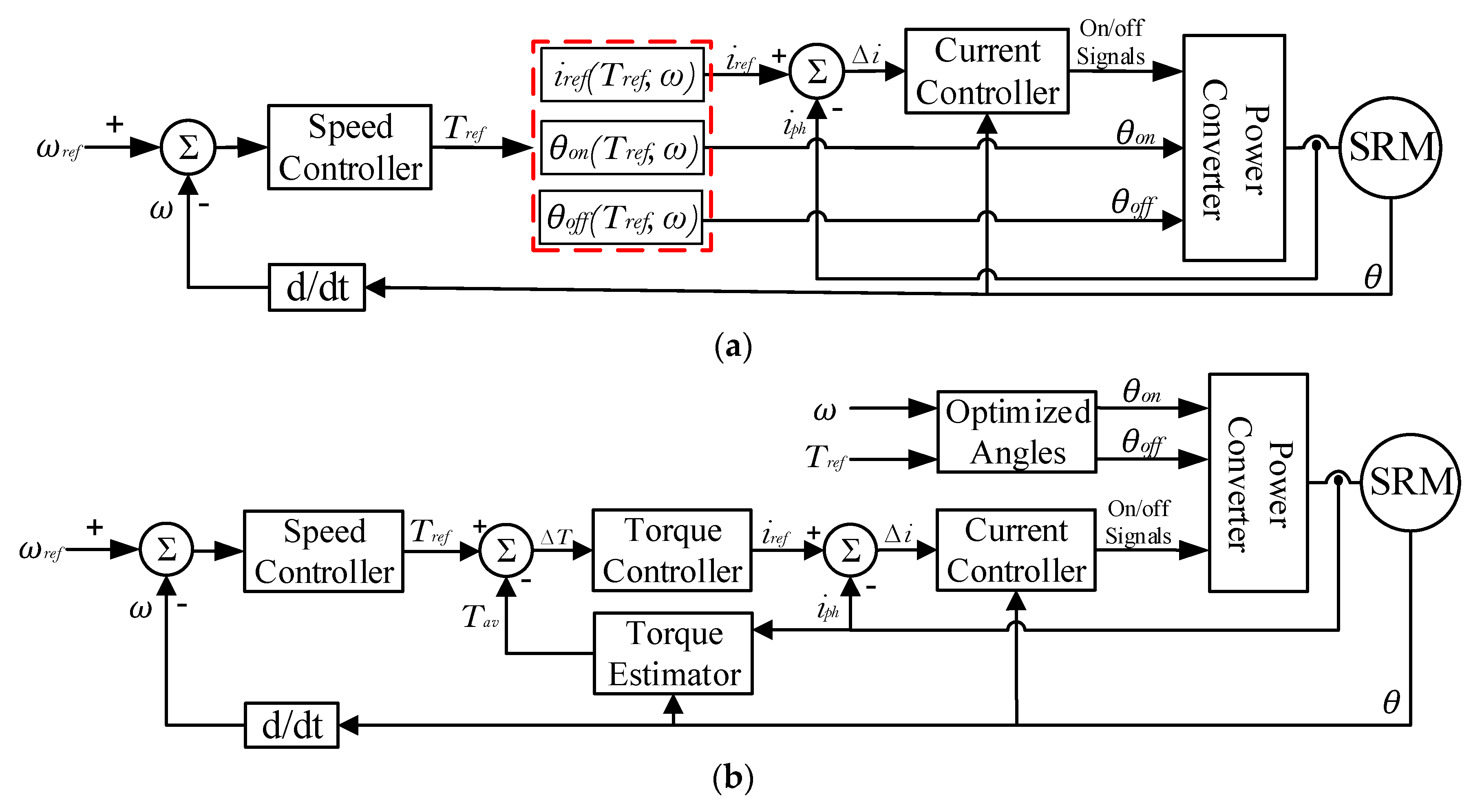
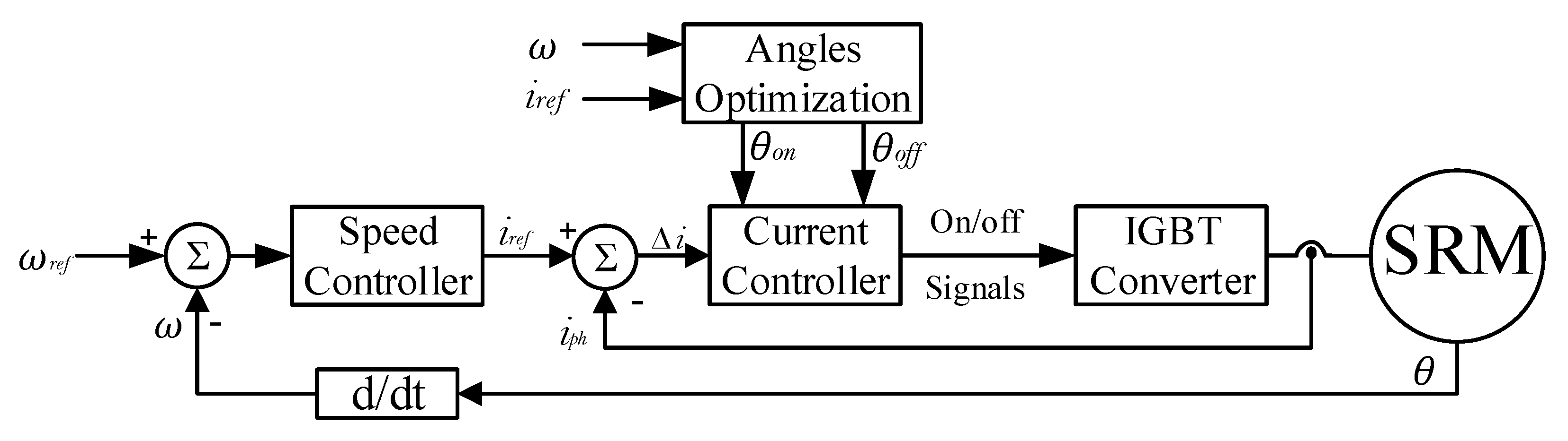
2. The Proposed Simple ATC Strategy

The existing ATC strategies for SRMs involve indirect average torque control (IATC) and direct average torque control (DATC), as seen in Figure 1. The IATC is an open-loop control. It does not have a feedback torque signal. On the other hand, the DATC has a closed-loop torque control.
The IATC has a simple structure compared to DATC, but a high sensitivity to the variation of machine parameters which are affected by the environmental conditions [31]. There are three control variables (θon, θoff, iref) that require a careful estimation. Due to the open loop control, the drive output is expected to deviate for its commanded torque value.
The DATC has a torque estimator that outputs the average torque (Tav). The estimation of Tav is a complicated task for real-time implementation. Hence, it complicates the control algorithm and affects the cost. However, the closed-loop torque control helps to track efficiently the command average torque without unwanted deviations, as in the case of IATC [10,14]. There are only two control variables (θon, θoff) because iref is outputted by the torque controller.
For any industrial applications including EVs, tradeoffs between cost and performance are always done to reach the best overall performance. Simple control algorithms offer a lower cost but may affect the performance. On the other hand, a high-performance control could be expensive. Therefore, this paper aims to achieve the high control performance of DATC with a very simple control algorithm, even simpler than IATC. Proper constraints are employed to guarantee the high-performance control behavior based on the simplified structure control strategy.
The proposed simple ATC (SATC) strategy is given in Figure 2. As seen, it has a very simple structure compared to the DATC and even IATC strategies. The outer loop speed control directly outputs the reference current (iref), instead of the reference torque (Tref). Besides, the proposed SATC strategy does not have a torque estimator. Moreover, the control parameters include only the θon and θoff angles, as iref is given by the outer loop speed controller. These control parameters (θon, θoff) are estimated offline using the optimization-based method discussed in the next Section.

3. Methodology

The conventional control of SRM aims basically to achieve an optimal efficiency and/or the maximum torque/current ratio. Several analytical formulations are proposed to maximize the drive efficiency [11,15,18] or to improve torque production [28,29,30]. However, these conventional methods use analytical formulations that are not enough to fulfill the best situation for EVs, especially for the torque ripple part. This is due to the highly nonlinear characteristics of SRM. Hence, a numerical solution for the optimum control parameters is essential to consider the vehicle requirements. Therefore, the control parameters for the proposed SATC strategy are optimized numerically to fulfill all the vehicle requirements for optimal drive. First, the optimization problem aims basically to achieve the minimum torque ripple to reduce vehicle noise and oscillations; it also aims to maximize drive efficiency to increase the mileage per charge. Second, new constraints for both the turn-on and turn-off angles are introduced to achieve the MTPA, wide speed ranges, and reliable operation. Third, torque constraint is proposed to guarantee fast-dynamics and a better torque tracking capability. Finally, a highly trusted model for the tested 8/6 SRM is employed for the accurate estimation of performance indices. The optimization problem is defined as follows.

3.1. The Optimization Problem

The optimization aims to minimize torque ripple (Tr) and to maximize efficiency (η). However, it is difficult to achieve the two objectives at the same time because different angles are required for each case. Hence, to achieve the required objectives, weighting factors (wr and wη) between torque ripple and efficiency are used. Therefore, a single objective criterion optimization can be implemented as follows:
F o b j ( θ o n , θ o f f ) = m i n ( w r T r T r b + w η η b η )
w r + w η = 1
subject to:
θ o f f m i n θ o f f θ o f f m a x
θ A θ o n θ B
T e T r a t e d   | ω , i r e f
The goal is to minimize the objective function (Fobj) which leads to the minimum torque ripples and maximum efficiency. Note that the efficiency part (ηb) is inversely related to the torque ripple part (Tr/Trb), as the objective is to maximize the efficiency and minimize the ripples. Several constraints are introduced by Equations (3)–(5). The detailed description of the constraints and the calculation process is given in next subsection.

3.2. Solution Method

To solve the aforementioned optimization problem, a highly trusted simulation model for the tested SRM is essential. The model is used for the accurate estimation of torque ripple (Tr) and efficiency (η). The model’s accuracy is very important, as it directly affects the optimization decision. Moreover, several quantities need to be carefully estimated through the solution process. First, the limits of the θon and θoff angles should be well determined, as several pairs of θon and θoff angles could have almost the same objective function, but only one pair achieves the best overall performance. Second, the rated motor torque should be calculated for a given current level and speed. This torque is used as a constraint to ensure a good tracking performance and a fast response. Third, the base values (Trb and ηb) have to be estimated accurately. A poor estimation of the base values affects the objective function and hence the final optimization decision. Note that the base values are changing at each operating point. Finally, the weight factors have to be set according to the desired optimization level.

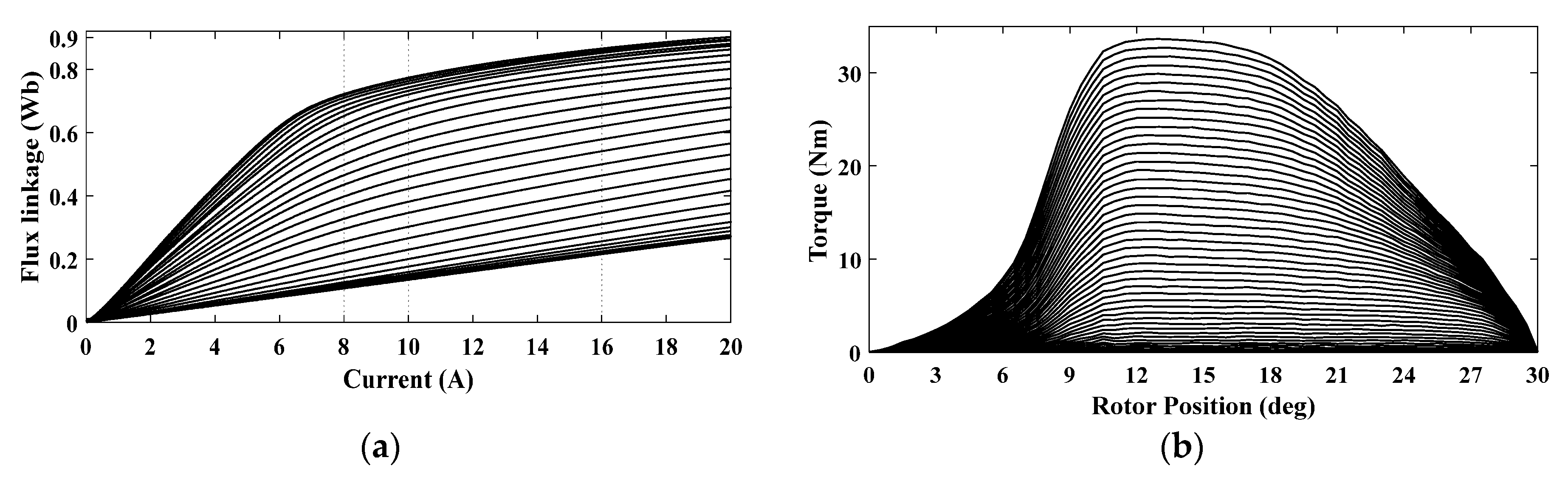
3.2.1. Machine Modeling

The SRM have double salient structures that lead to highly nonlinear magnetization characteristics. The flux-linkage λ(i,θ), inductance L(i,θ), and torque T(i,θ) are functions of both current magnitude (i) and rotor position (θ). The voltage equation is given as follows [25]:
v k = R i k + λ k ( i k , θ ) t ;   λ k ( i k , θ ) = L k ( i k , θ ) i k
The electromagnetic torque of kth phase (Tk) is given as:
T k = 1 2 L k θ i k 2
For SRM with q-phases, the total electromagnetic torque (Te) can be represented as:
T e = k = 1 q T k
The equation for mechanical dynamics is expressed as:
T e T L = B ω m + j d ω d t
For the best accurate modeling of the tested 8/6 SRM, its magnetic characteristics are experimentally measured. The phase flux linkage k) is measured using the phase voltage (vk) and phase current (ik) data. For each desired rotor position (θ), a pulsed dc voltage is applied to the phase winding; then, vk and ik are measured and recorded. Equation (10) is used to estimate the flux from the measured voltage and the current data [25].
λ k ( n ) = k = 1 n ( v k ( k ) R i k ( k ) ) T s + λ ( 0 )
On the other hand, the torque is measured directly using a torque transducer. The torque and current data are recorded at each rotor position. To generate the complete motor characteristics, the above measurements of flux and torque data are repeated several times regarding the desired resolution of rotor position, that is 0.5 mechanical degrees. The final obtained flux and torque characteristics are shown in Figure 3. As noted, both the flux and torque data are highly nonlinear functions of the current and rotor position. These data are employed in the form of look-up tables to represent the machine using MATLAB Simulink [25]. The geometrical dimensions of the studied SRM are gathered in Table 1.
The Simulink model is used to estimate the torque ripples and efficiency as follows [4,10,29]:
T r = T m a x T m i n T a v
The average torque (Tav) can be calculated over one electric cycle (τ).
T a v = 1 τ 0 τ T e ( t ) d t
The efficiency (η), average supply current (Iav), and RMS supply current (IRMS) can be expressed as:
η = ω   T a v V D C   I a v ;                 I a v = 1 τ 0 τ i s ( t ) d t             I R M S = 1 τ 0 τ i k 2 ( t ) d t

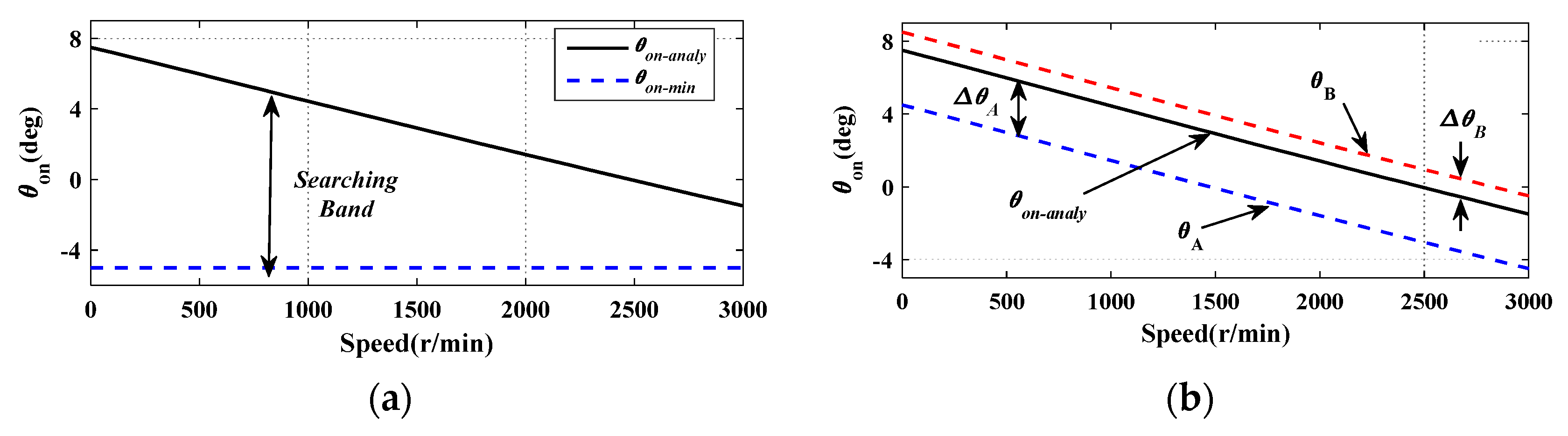
3.2.2. The Limits of Switching Angles (θon, θoff)

During the optimization process, several pairs of θon and θoff angles can provide the same objective function or a very close one. However, only few pairs should be selected. As the θon can directly affect the current, torque, and operating speed range, the limits of the θon angle are of the greatest importance. As the motor speed increases, the θon angle should be advanced along with the speed and also with the current level.
Several analytical formulations have been developed for obtaining the optimum value of the θon angle. Among these techniques, in previous authors’ work [29], a proposed control technique is introduced to determine the most efficient θon. It calculates the effective amount of phase inductance Leff(i, θ) and its derivative kb-eff(i, θ). Hence, this method is capable of an accurate consideration of the effect of back-emf voltage at low and high speeds. The optimum analytical solution for θon is calculated as a function of ω and iref, as given by Equation (14). The full details of Equation (14) are given in [29]. The solution scenario of Equation (14) is as follows:
(1)
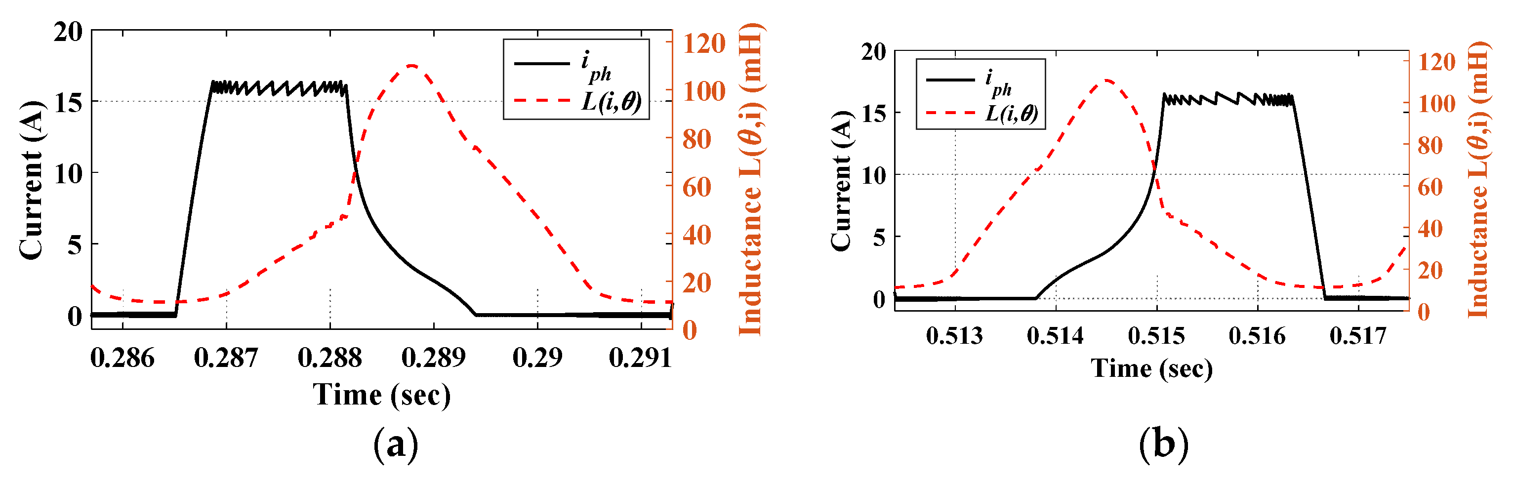
Fitting of phase inductance L(i, θ) against the rotor position (θ) in the minimum inductance zone. In this zone, the inductance is only a function of θ. Hence, a simple exponential function is enough for the fitting L ( i ,   θ ) = a e b θ + c . The coefficients a, b, and c are the fitting coefficients,
(2)
Calculation of parameter (kb) as the derivative of inductance k b = d L ( i ,   θ ) / d θ ,
(3)
Determination of the initial turn-on angle θ o n i n i t i a l = θ m L u i r e f ω V D C ,
(4)
Estimation of the effective values Leff(i, θ) and kb-eff(i, θ) as the average values of L(i, θ) and kb, respectively, over the interval [θon-initial, θm],
(5)
Using Equation (14) to determine the best analytical solution for the turn-on angle.
θ o n a n a l y = θ m L e f f ( i , θ ) R + k b e f f ω l n ( 1 i r e f R + k b e f f ω V D C )
In general, if the θon angle is higher than the one calculated from Equation (14), the inductance will limit the current to reach its reference value. As a result, the motor will not be able to produce enough torque to reach the desired speed. Hence, the maximum limit of the θon angle is the optimum value that is calculated by Equation (14). The theoretical minimum limit of θon is −θm = −8°. This limit depends on the operating speed range. It could be chosen as −5°, as seen in Figure 4a. However, the chosen limits for the θon angle (in Figure 4a) are very large and may cause a huge conflict in the final optimization decision. Hence, the proposed limits are shown in Figure 4b. The limits (θA and θB) are defined as a function of θon-analy (calculated by Equation (14)) and the margins ΔθA and ΔθB, as follows:
θ A = θ o n a n a l y Δ θ A
θ B = θ o n a n a l y + Δ θ B
ΔθA and ΔθB are correlated with the required level of optimization. In this paper, ΔθA is set to 3° and ΔθB is set to 1°. These limits will not only achieve the desired optimization level but also ensure a smooth variation of the firing angles with motor speed and current. They also involve the production of the MTPA.
The limits of the θoff angle depend on the θon angle. The conduction angle should not be less than 15° for proper torque production in 8/6 SRM [30]. Hence, in general, θ o f f m i n   = θon + 15°. The theoretical maximum limit of the θoff angle ( θ o f f m a x ) is 30° for 8/6 SRM, but this limit depends on the speed and current levels, as the motor current should decay back to zero at/before the aligned position [29]. Therefore, the θoff needs to be less than 30° to give the current enough time to decay to zero. The θ o f f m a x is set to 25°.

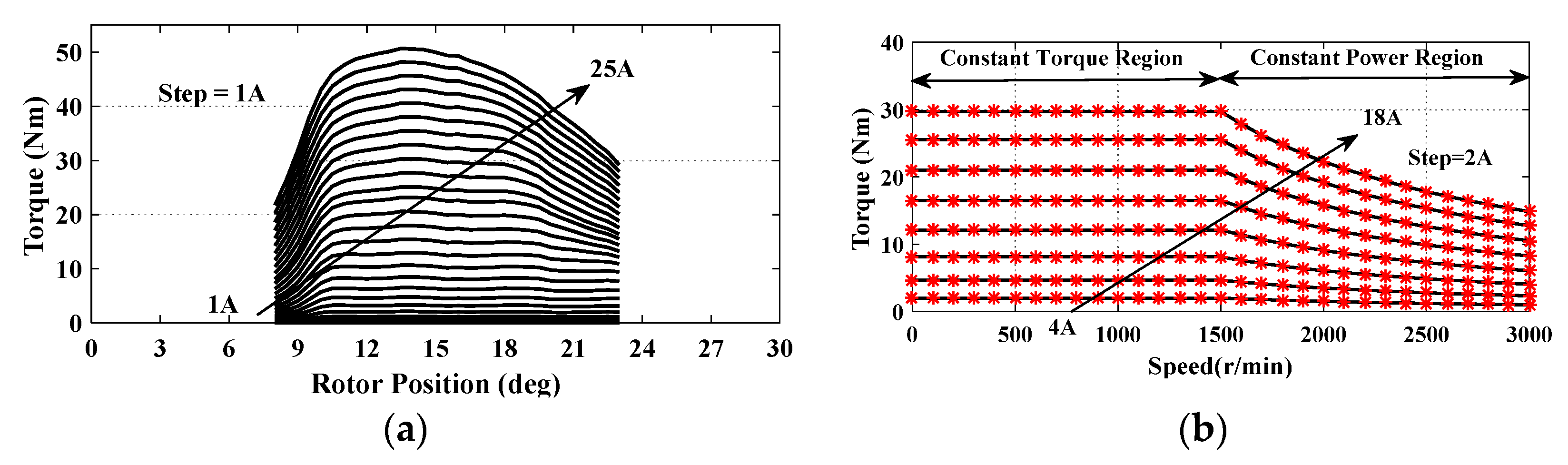
3.2.3. Estimation of the Rated Torque for a Given Current Level

For a given reference current and speed, the motor rated torque (Trated) should be known, as it is a very essential constraint in Equation (5). The proposed current to torque conversion is achieved based on the measured magnetic characteristics of the tested 8/6 SRM. For 8/6 SRM, the ideal conduction angle is 15°. Hence, the most efficient average torque can be calculated over the interval [θm, θm + 15°], as it is the best interval for torque production, as shown in Figure 5a. Hence, the relationship of torque as a function of phase-current can be developed. The torque-speed curves at different current levels and up to 3000 r/min (double the rated speed of 1500 r/min) are illustrated in Figure 5b.
In ATC, the conduction angle is almost higher than the ideal one (15°). This, in turn, improves the current overlap and thus helps to reduce torque ripples. It also improves torque production. The proposed current to torque conversion is done over the minimum possible conduction angle (15°). This always ensures the motor’s capability to produce the commanded level of torque. Moreover, it guarantees a high-performance torque tracking capability even under variations of machine parameters. That is why there is no need for closed-loop torque control. Furthermore, it eliminates the need for the online estimation of the average torque, which is a complicated task with a questionable accuracy in real-time implementation.

3.2.4. Estimation of Base Values

At each operating point (ω and iref), the base values of the objectives are the maximum or the minimum values for their corresponding criterion. These base values are defined as follows:
T r b ( θ o n , θ o f f ) | ω , i r e f = m i n ( T r )
η b ( θ o n , θ o f f ) | ω , i r e f = m a x ( η )
The base values (Trb and ηb) are estimated within a two-dimensional searching algorithm. The flowchart of the searching algorithm is shown in Figure 6. For each operating point (ω and iref), the θon and θoff angles vary by small steps of 0.2°. Then, the torque ripple and efficiency are estimated within the Simulink model. When the search ends, the minimum value of torque ripple and the maximum value of efficiency are set as the base values.

3.2.5. Estimation of Weight Factors

The weight factors (wr and wη) are set according to the desired level of optimization. In this research, greater attention is directed to reducing the torque ripple. The weight factors are set to wr = 0.6 and wη = 0.4. For different levels of optimization, different weight factors can be employed.

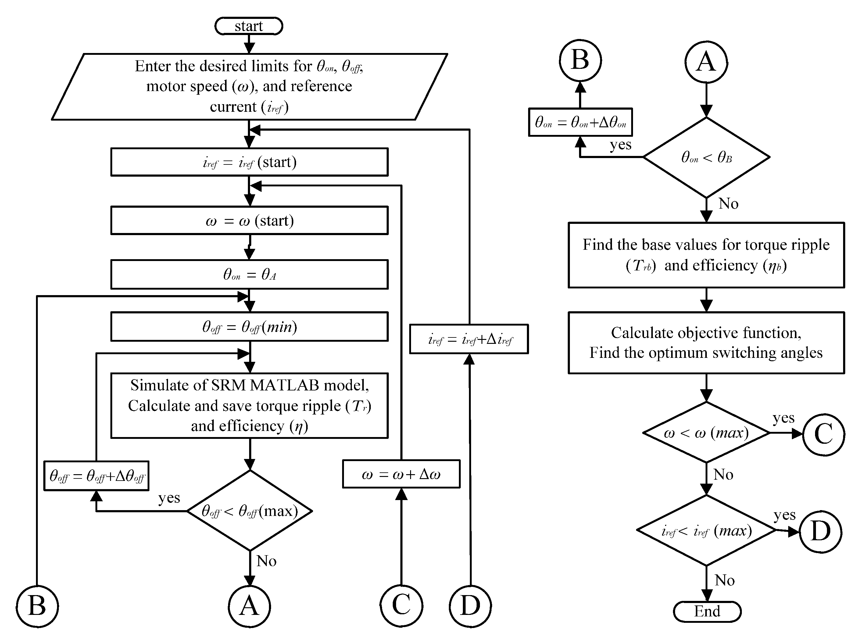
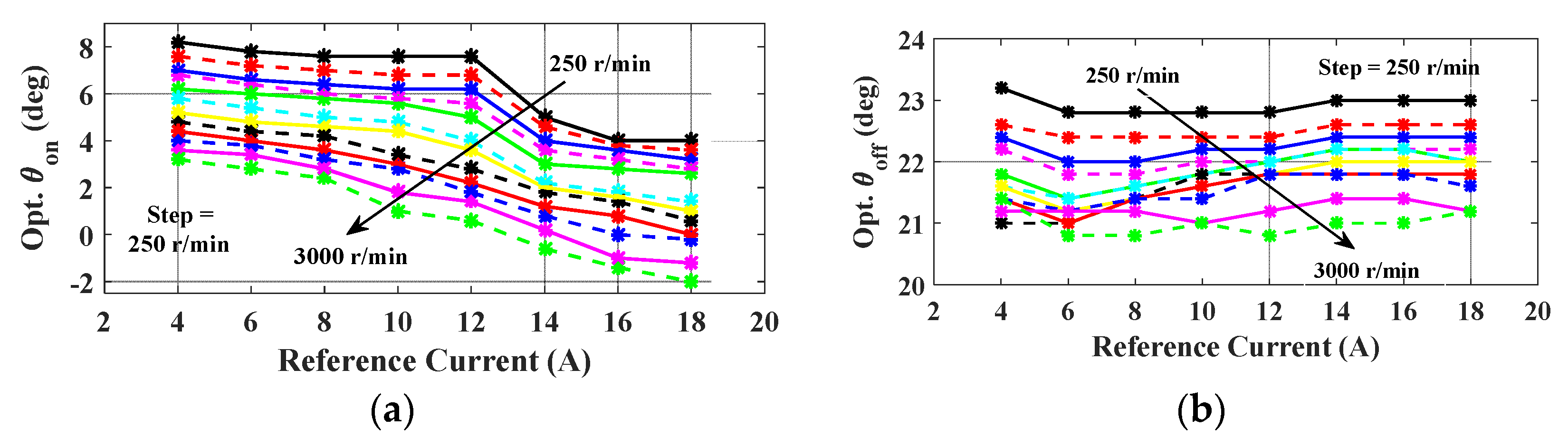
3.2.6. The Optimum Solution for Switching Angles

Solving Equation (1) gives the optimum excitations parameters that fulfill the smallest torque ripple and the highest efficiency for various operation points. They also involve the MTPA and high torque dynamics within the proposed constraints. The solution is achieved through the flowchart in Figure 6. The solution scenario for a defined operating point (ω and iref) is as follows:
(1)
Define the operating point by the desired speed (ω) and reference current (iref),
(2)
Use Equation (14) to determine the best analytical turn-on angle (θon-analy),
(3)
Choose the margins ΔθA and ΔθB. Then, define the minimum and maximum limits (θA and θB) for the turn-on angle (θon),
(4)
Define the minimum and maximum limits ( θ o f f m i n and θ o f f m a x ) for the turn-off angle. For the tested 8/6 SRM, θ o f f m i n   = θon + 15°, and θ o f f m a x   = 25°,
(5)
Set θon = θA (the starting point) and θoff = θ o f f m i n (the starting point),
(6)
Run the simulation model of SRM, estimate the required indices (torque ripples and efficiency), and save the data,
(7)
Increase θoff by the desired resolution (Δθoff). Hence, θoff = θoff + Δθoff. Δθoff is set to 0.2°,
(8)
Repeat step 6 till θoff = θ o f f m a x ,
(9)
Increase θon by the desired resolution (Δθon). Hence, θon = θon + Δθon. Δθon is set to 0.2°,
(10)
Repeat steps 7 to 9 till θon = θB,
(11)
Estimate the base values (Trb and ηb) from the saved data using Equations (17) and (18),
(12)
Choose the weight factors (wr and wη) according to the desired optimization level,
(13)
Calculate the objective function (Fobj) using Equation (1),
(14)
Define the optimum switching angles that correspond to the minimum objective function.
The above scenario gives the optimum switching angles for one operating point. Therefore, it must be repeated several times according to the number of desired operating points. In this paper, the study involves 96 operating points. iref is changed from 4A to 18A in steps of 2A, which means 8 levels, whereas ω is changed from 250 r/min to 3000 r/min in steps of 250 r/min, which means 12 levels. The complete optimum solution for switching angles is given in Figure 7. Clearly, for the same speed, the θon angle is advanced with the increasing current level, as seen in Figure 7a. Further, the variation of the θoff angles is small, as seen in Figure 7b. The small variation of the θoff angles can help for further simplification of the control algorithm. An average fixed value for the θoff angles can be used to simplify the control algorithm without scarifying the machine performance. However, this assumption may have a negative effect on torque ripple, but it will have a better reflection on system simplification. In this research, the complete data of the θoff angles are used in the form of look-up tables to achieve better precision.

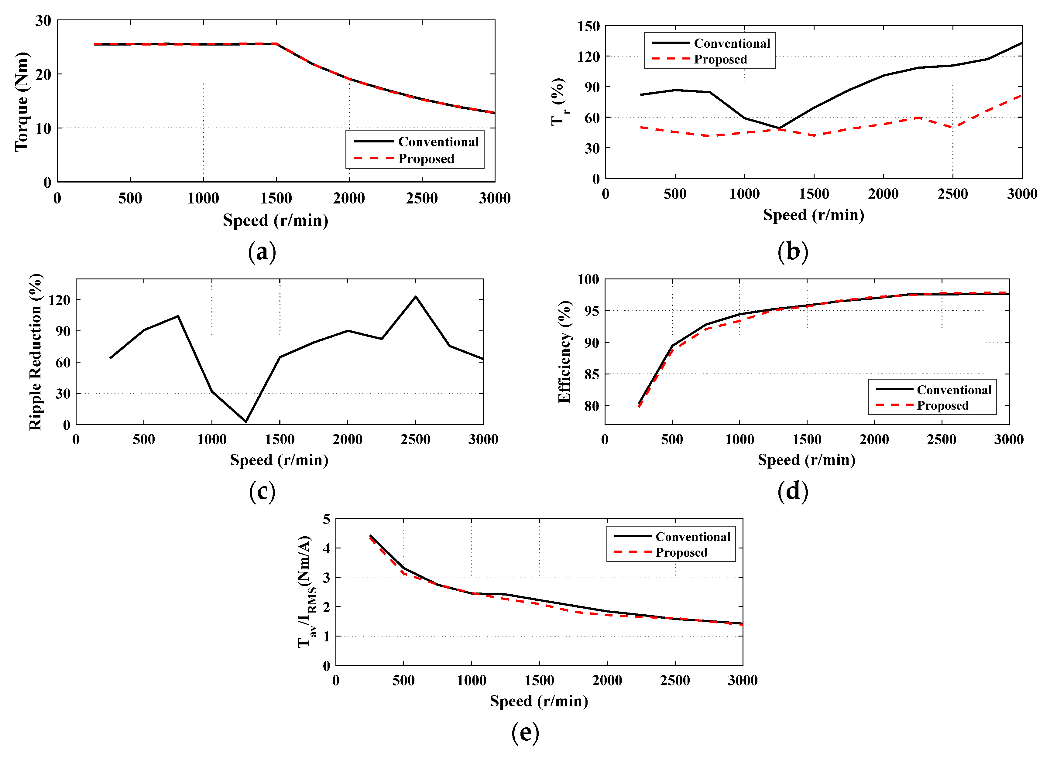
4. Simulation Results and Discussion

To show the effectiveness and feasibility of the proposed SATC strategy and the introduced optimization problem, solution method, defined limits, and constraints, the present section is organized as follows. First, the fidelity of the optimization problem is investigated in Section 4.1. In this section, the proposed SATC strategy, along with the optimum solution for the introduced optimization problem is compared to the analytical solution of [18] under steady-state conditions. The reason for choosing this reference among the literature is that it involves optimum analytical solutions for both the turn-on and turn-off angles. It also gives a comparison with other conventional methods while obtaining the best efficiency. Second, to investigate the system dynamic performance as it applies to EVs, the closed-loop DATC of Figure 1b is used for comparison in Section 4.2. In this case, the obtained solution for the switching angles in Figure 7 is used for both techniques (the proposed SATC and the DATC). The comparison is basically meant for the investigation of the dynamic performance.

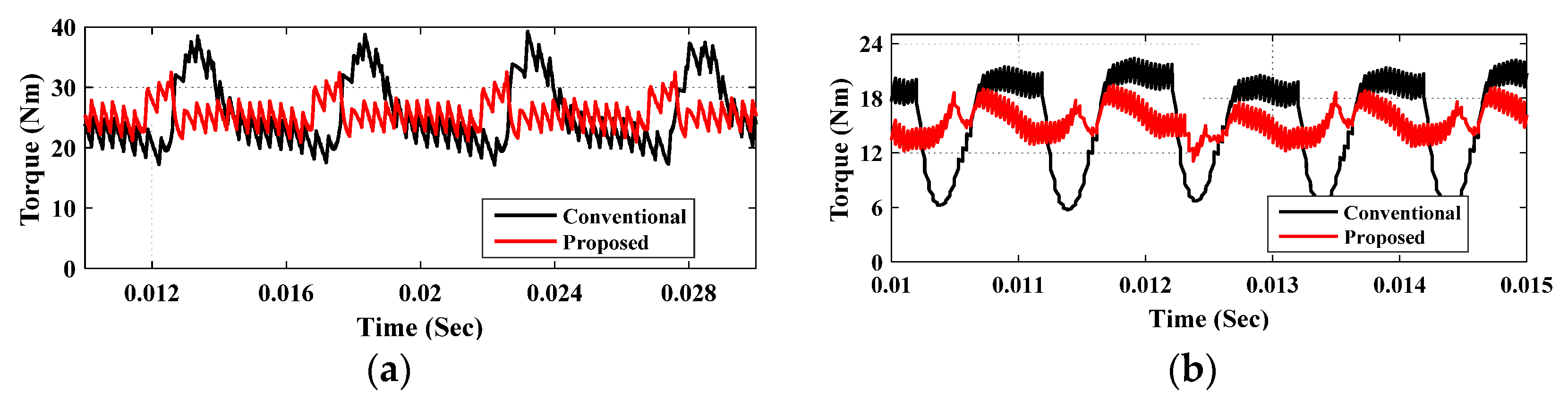
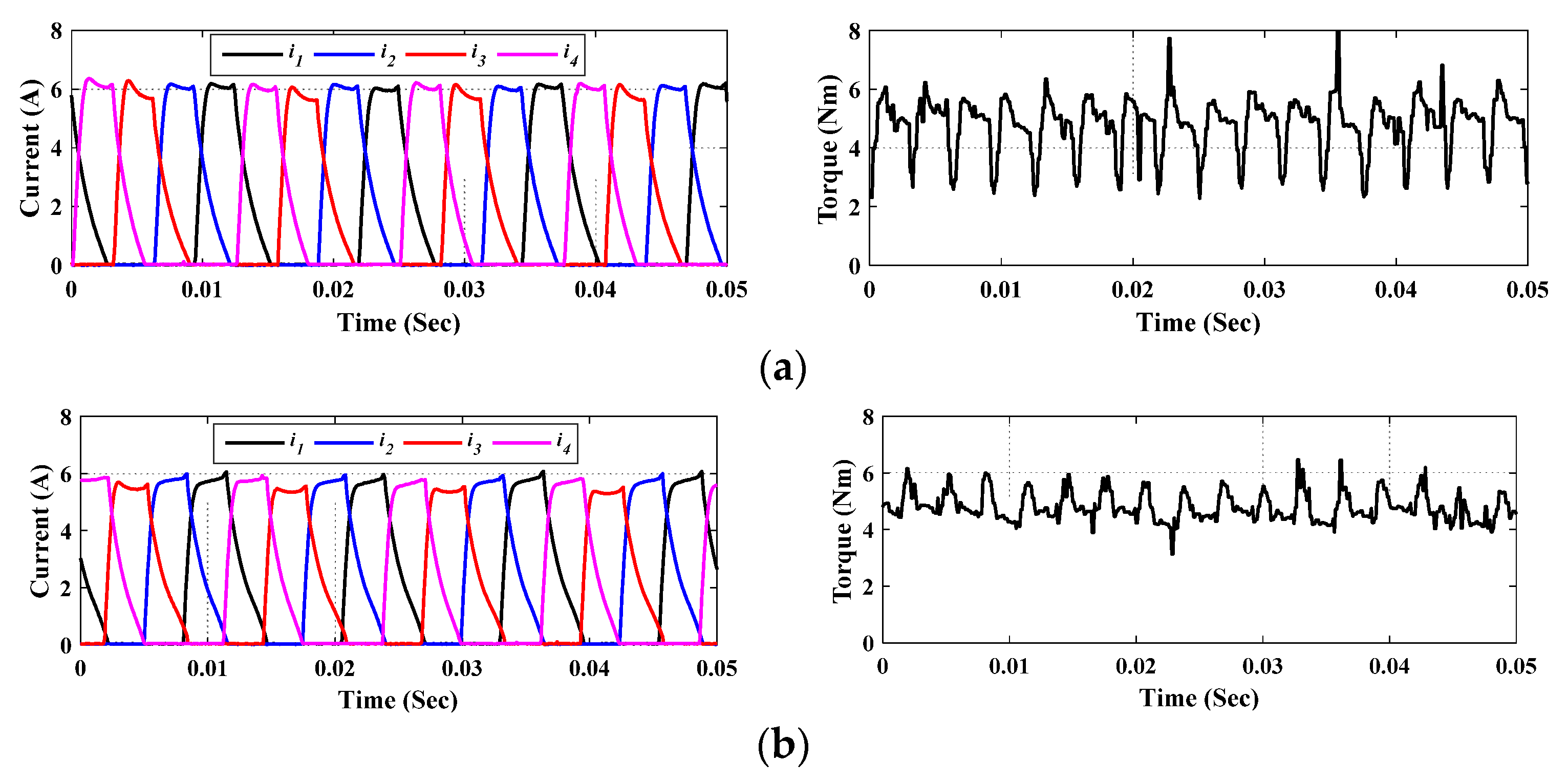
4.1. The Steady-State Performance

Figure 8 shows the steady-state performance of the proposed SATC strategy compared to the conventional analytical method of [18]. The motor is loaded with its full load torque of 25.6 N.m. Above the base speed (1500 r/min), the motor produces a constant power (i.e., the rated power, 4 kW), which means that the torque has to be reduced with increasing the speed, as seen in Figure 8a. The torque ripple is shown in Figure 8b. As noted, the proposed SATC has the minimum torque ripple over the entire speed range. The torque ripple is significantly reduced compared to the conventional method of [18]. The percentage reduction of ripple is given in Figure 8c. The average value of torque ripple reduction over speed range is 72.43%. However, the conventional method has a relatively higher efficiency and higher torque/current ratio, especially at low speeds, as illustrated in Figure 8d,e, respectively. The difference is very minor, which verifies the MTPA and efficiency optimization for the proposed SATC. It can be concluded that, under the same operating conditions, the optimized switching angles based on the proposed SATC strategy succeeded in significantly reducing the torque ripple while obtaining almost the same efficiency and the same torque/current ratio. Therefore, the SATC is a very advantageous solution for EVs applications.
Further details for the torque ripple can be seen in Figure 9. This Figure shows the steady-state torque curves at low speed (500 r/min) and high speed (2500 r/min). As seen, the SATC has the best torque profile with the minimum torque ripple. Note that, at low speed (500 r/min), its torque ripple is minor, which means less noise and oscillation for the vehicle’s body. As the speed increases, the ripple also increases, but they can be filtered by vehicle inertia.

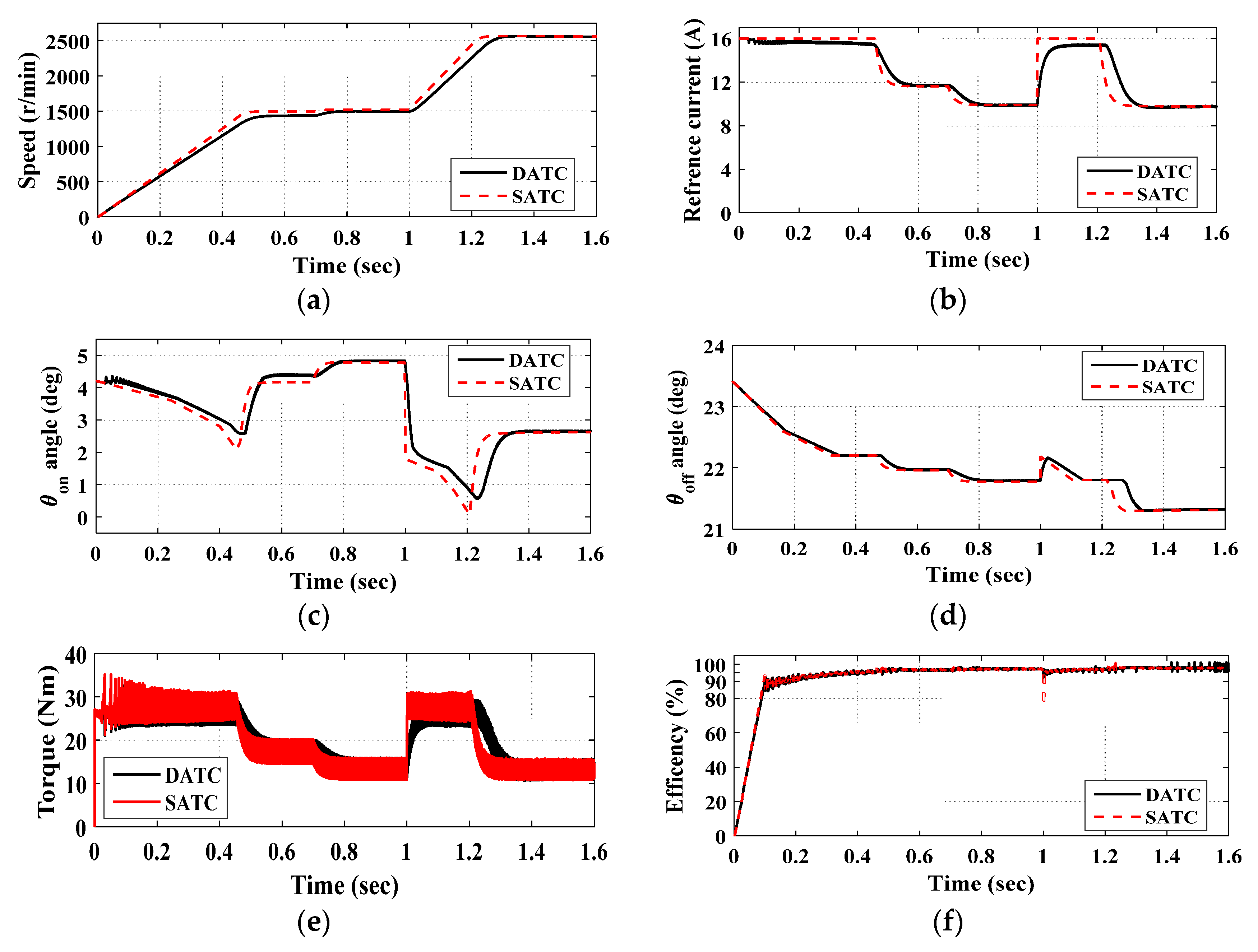
4.2. The Dynamic Performance

The dynamic performance for the proposed SATC strategy is investigated compared to the dynamic performance of the DATC of Figure 1b. The reason for choosing DATC is that it has a very good dynamic torque performance, as it uses a closed-loop torque control scheme. Note that the optimum solution of switching angles is used for both techniques (SATC and DATC). Hence, the torque ripple and efficiency will be almost the same under a steady state. The difference appears under dynamic conditions.

4.2.1. Sudden Change in Reference Speed and Load Torque

Figure 10 shows the simulation results under a sudden change in reference speed and load torque. The reference speed is changed from 1500 to 2500 r/min at 1.0 s. The load torque is suddenly changed from 17 to 13 N.m at 0.7 s. Both the SATC and DATC can properly track the reference commanded speed, as shown in Figure 10a. As noted, the SATC has a better tracking performance, as it directly controls the motor current. It also has a faster dynamic behavior for its reference current (Figure 10b) compared to DATC. This is because DATC has a torque controller (PI) that outputs the reference current with time delay. The variation of the θon and θoff angles is given in Figure 10c,d, respectively. A smooth and adaptive variation according to the motor speed and current is observed. The optimized angles effectively reduce the torque ripple as desired, leading to a good torque profile, as seen in Figure 10e. The motor has a very good efficiency, as shown in Figure 10f. The efficiency increases with the motor speed. Hence, SRMs are preferred to operate under high speeds.
As a conclusion, the SATC has a better control performance compared to DATC and offers a very simple control algorithm. Besides, the estimated excitation parameters (θon and θoff) reduce the torque ripple in a very efficient way to match the vehicle requirements. Moreover, the motor has a very good efficiency even at low speeds.

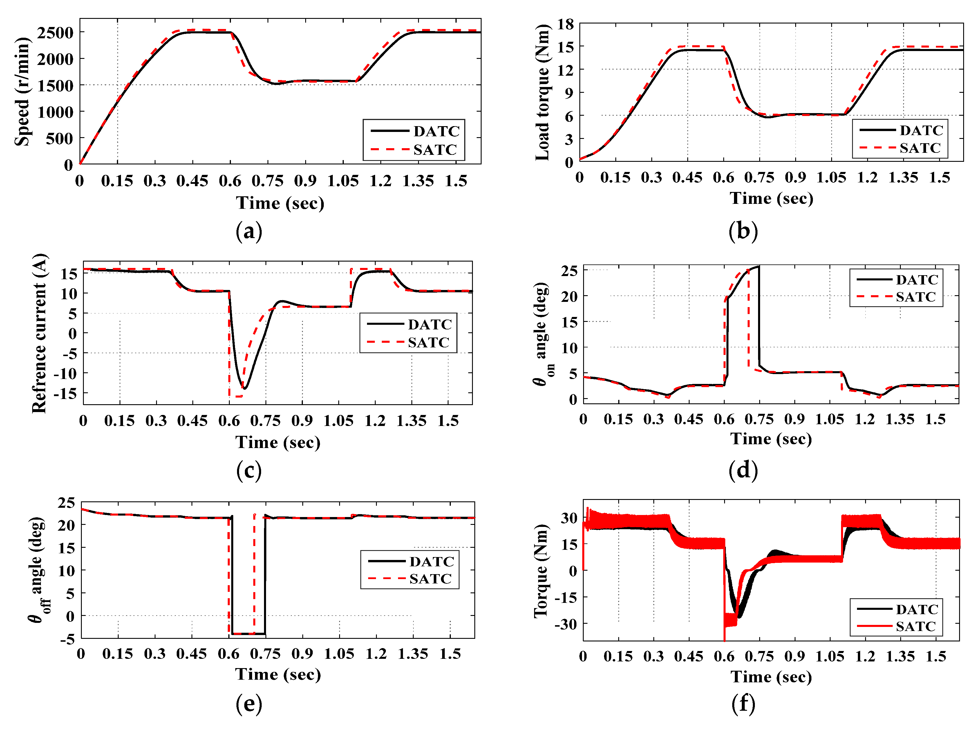
4.2.2. Acceleration and Deceleration with Electric Vehicle Loading

Figure 11 shows the simulation results under acceleration and deceleration conditions. The motor speed is shown in Figure 11a. The vehicle starts to decelerate at 0.6 s. Hence, the reference current goes negative, as shown in Figure 11c, to brake the motor. The motor operates in the forward generating mode. Therefore, the excitation angles are changed from motoring action to generating action. The phase windings are excited in the increasing inductance zone under motoring and in the decreasing inductance zone under generating. The variation of excitation angles is given in Figure 11d,e. An adaptive variation under motoring and generating modes is observed. The optimized angles kept a good torque profile under motoring and generating modes, as shown in Figure 11f. The torque ripple is always kept minor.
The phase current and inductance under motoring and generating modes are illustrated in Figure 12. As noted, for motor action, the phase windings are excited in the increasing inductance zone, and for generator action, the phase windings are excited in the decreasing inductance zone.

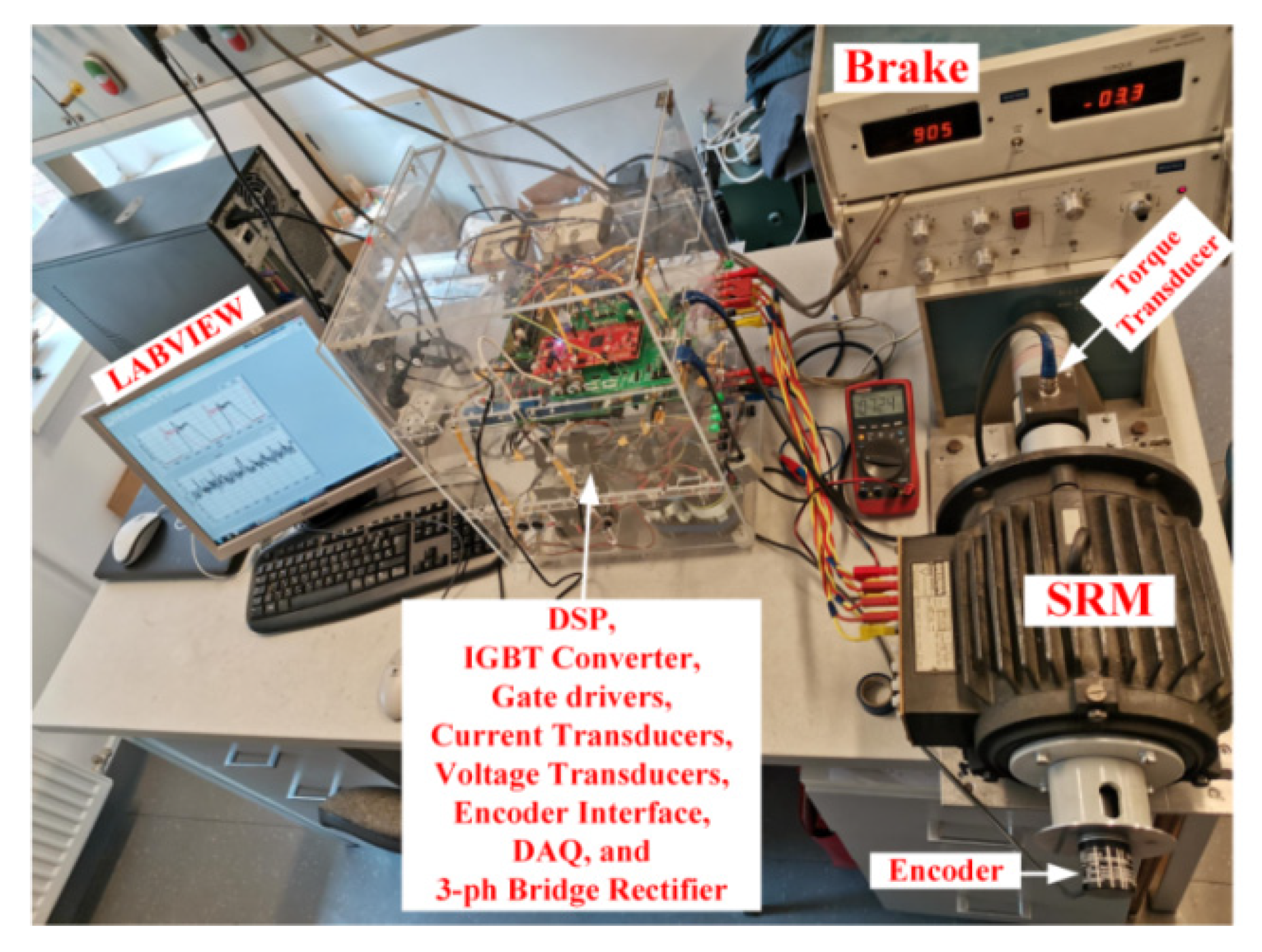
5. Experimental Verification

In order to validate the theoretical findings presented earlier, the experimental testbed shown in Figure 13 was constructed. A four-phases 8/6 SRM is coupled via a torque sensor with an electromagnetic brake (MAGTORL model 4605c). The SRM is supplied by an IGBT asymmetrical bridge converter. A 1024 PPR incremental encoder is used to provide the rotor position feedback signal. The TMS320F28335 experimental board is employed to implement the control algorithm. High accuracy and linearity current sensors (LAH50-P) are used to measure the phases’ currents. The DC power is supplied through a three-phase transformer, a three-phase diode rectifier, and a capacitor. The data are collected and plotted using a data acquisition board (DAQ-6009) with LabView software. The electromagnetic brake has a maximum braking torque of 6 N.m, which is the adopted torque limit for experimental verification.
The experimental verifications start by verifying the accuracy of the SRM model in Section 5.1. The model accuracy is essential, as the performance indices (torque ripples and efficiency) are calculated within the model. Any calculation error will affect the optimization decision. Secondly, the verifications involve a quantitative analysis and a comparison between the conventional method of [18] and the proposed one in Section 5.2.

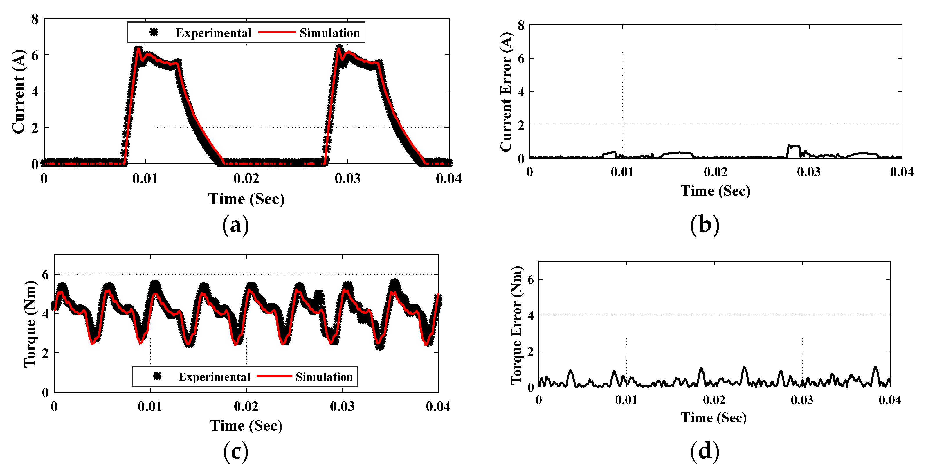
5.1. Model Verification

The model accuracy is verified experimentally. The simulated current and torque waveforms are compared with the experimentally obtained waveforms, as shown in Figure 14. Besides, Table 2 gives the control parameters and the details of comparison. As seen in Figure 14a, the measured and simulated current waveforms are in very good agreement. The current error is very small, as shown in Figure 14b. Its RMSE is 0.2007A, which reflects the good accuracy of the current modeling. Figure 14c gives a comparison between the measured and simulated torque curves. A good agreement is also observed. The torque errors in Figure 14d seem a bit higher compared to the current errors. However, this is not a problem. The most important measure is the average torque value, as it is used for efficiency calculation. The simulated and measured average values of torque are given in Table 2. Besides, Table 2 also gives a comparison between the measured and simulated torque ripples and efficiencies. A very good agreement between the measured and simulated quantities in Table 2 is observed. This good agreement verifies the model’s accuracy, and hence the fidelity of the obtained parameters.

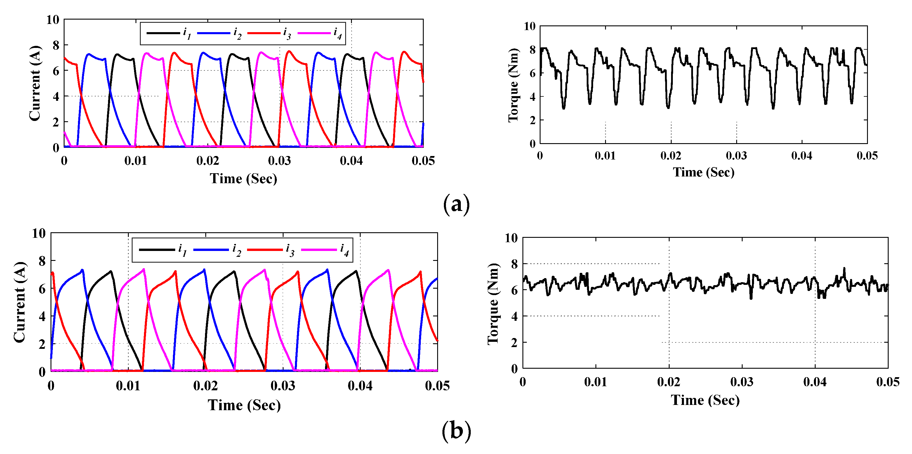
5.2. Quantitative Analysis

Figure 15 shows the experimentally measured results for the conventional and proposed SATC strategies at 627 r/min. In both cases, the motor is loaded with the same mechanical load of 6.3 N.m, and it is running at the same speed of 627 r/min. The only difference are the control parameters. The conventional control of [18] aims basically to maximize the drive efficiency; as a result, the torque ripple is very high, as seen in Figure 15a. The high torque ripple is totally unacceptable for EVs, as it causes noise and vibration. In contrast, the proposed SATC uses a multi-objective cost function that aims to minimize the torque ripple and maximize the efficiency while obtaining the production of the MTPA. As seen in Figure 15b, the proposed SATC has efficiently reduced the torque ripple.
Figure 16 gives another comparison between the conventional and proposed SATC strategies, at a higher speed (806 r/min). In both cases, the motor is loaded with the same mechanical load of 4.8 N.m while running at the same speed of 806 r/min. The conventional control has a very high torque ripple compared to the proposed SATC, as seen in Figure 16a,b, respectively.
Table 3 gives a quantitative analysis for the experimentally measured results of Figure 15 and Figure 16. At 627 r/min, the proposed SATC has the minimum torque ripple of 30.822%, compared to 68.763% for the conventional method. Besides, the proposed SATC has a higher torque to current ratio. It also has a very close efficiency. At 806 r/min, the proposed SATC has the minimum torque ripple of 36.254%, compared to 72.821% for the conventional method. Besides, the proposed SATC has a higher torque to current ratio. It also has a very close efficiency. It can be concluded that the proposed SATC has a significant reduction of torque ripple to fit EV application. Moreover, it succeeded in maintaining a higher torque/current ratio, and has a very good efficiency. As the speed increases, the torque ripple increases, but they can be filtered by vehicle inertia.

6. Conclusions

In this paper, a numerical estimation method for the optimum excitation parameters of SRM based on a simple structure ATC strategy is presented. The proposed control offers a promising performance for EVs, as it achieves the vehicle requirements of reduced ripple, high efficiency, MTPA, wide speed range, easy implementation, and low cost. The torque ripple is reduced through the numerical optimization of the switching angles. The turn-on angles are analytically estimated. Then, a proper band is set for the optimization problem. This, in turn, involves the MTPA and allows the motor to be used for the entire possible range of speed control. It also ensures adaptive and smooth variations of the control parameters, along with the speed and torque, which in turn improves the driving capability. The proposed control provides a good profile of generated torque with reduced ripples, especially at low speeds, which means a minimum vehicle oscillation and noise. It is found that the proposed control scheme reduces the torque ripple of SRM by about 72.43% compared to the literature. Besides, it succeeds in maintaining a very good efficiency and torque/current ratio compared to the literature. Moreover, the fast-dynamic response and good tracking performance with parameter insensitivity are guaranteed with the predefined torque constraints. Apart from that, for additional reductions of torque ripples, the reference current signal can be compensated in future works using a fuzzy logic controller and/or artificial neural networks involving the measured machine characteristics.

Author Contributions

Conceptualization, M.H.; data curation, M.H. and M.N.I.; formal analysis, M.H. and M.N.I.; investigation, M.H. and A.A.M.; methodology, M.H.; project administration, L.S.; resources, A.A.M., H.R. and L.S.; software, M.H.; supervision, L.S.; validation, M.H.; visualization, H.R. and M.N.I.; writing—original draft, M.H.; writing—review & editing, A.A.M., H.R., M.N.I. and L.S. All authors have read and agreed to the published version of the manuscript.

Funding

This research received no external funding.

Conflicts of Interest

The authors declare no conflicts of interest.

Nomenclature

SymbolDefinitionUnit
BThe combined rotor and load viscous friction coefficientKg.m2/s
FobjThe objective function
IavThe average supply currentA
ikThe phase current of kth phaseA
irefThe reference currentA
isThe instantaneous supply currentA
JThe combined rotor and load inertia coefficientKg.m2
LkThe phase inductance of kth phaseH
LuThe unaligned/minimum inductanceH
nThe number of sampling point under calculation
qThe number of motor phases
RThe phase resistanceΩ
TavThe average torqueN.m
TeThe total electromagnetic torqueN.m
TkThe phase torque of kth phaseN.m
TLThe load torqueN.m
TmaxThe maximum value of instantaneous motor torqueN.m
TminThe minimum value of instantaneous motor torqueN.m
TrThe torque ripple N.m
TratedThe rated motor torque for a given value of reference current and speedN.m
TrbThe base value of torque ripple N.m
TrefThe reference torqueN.m
TsThe sampling periods
VDCThe DC supply voltage V
vkThe phase voltage of kth phaseV
wrThe weight factor of torque ripple
wηThe weight factor of efficiency
θThe rotor positionDeg.
θAThe minimum limit of the turn-on angleDeg.
θBThe maximum limit of the turn-on angleDeg.
θmThe angle where rotor poles start to overlap with stator poles Deg.
θonThe turn-on angleDeg.
θ o n a n a l y The analytically obtained turn-on angle Deg.
θoffThe turn-off angleDeg.
θ o f f m i n The minimum limit of the turn-off angleDeg.
θ o f f m a x The maximum limit of the turn-off angleDeg.
λkThe phase flux linkage of kth phaseWb
λ(0)The initial flux-linkageWb
ηThe efficiency
ηbThe base value of efficiency
ωThe angular velocity of rotorRad/s
τThe time of one electric cycles
ΔθAThe lower margin of the turn-on angleDeg.
ΔθBThe higher margin of the turn-on angleDeg.

References

  1. Bramerdorfer, G.; Tapia, J.A.; Pyrhonen, J.J.; Cavagnino, A. Modern Electrical Machine Design Optimization: Techniques, Trends, and Best Practices. IEEE Trans. Ind. Electron. 2018, 65, 7672–7684. [Google Scholar] [CrossRef]
  2. Chen, H.; Yan, W.; Gu, J.; Sun, M. Multiobjective Optimization Design of a Switched Reluctance Motor for Low-Speed Electric Vehicles with a Taguchi–CSO Algorithm. IEEE/ASME Trans. Mechatron. 2018, 23, 1762–1774. [Google Scholar] [CrossRef]
  3. Bostanci, E.; Moallem, M.; Parsapour, A.; Fahimi, B. Opportunities and Challenges of Switched Reluctance Motor Drives for Electric Propulsion: A Comparative Study. IEEE Trans. Transp. Electrif. 2017, 3, 58–75. [Google Scholar] [CrossRef]
  4. Nguyen, D.-M.; Bahri, I.; Krebs, G.; Berthelot, E.; Marchand, C.; Ralev, I.; Burkhart, B.; De Doncker, R.W. Efficiency Improvement by the Intermittent Control for Switched Reluctance Machine in Automotive Application. IEEE Trans. Ind. Appl. 2019, 55, 4167–4182. [Google Scholar] [CrossRef]
  5. Husain, T.; Elrayyah, A.; Sozer, Y.; Husain, I. Unified Control for Switched Reluctance Motors for Wide Speed Operation. IEEE Trans. Ind. Electron. 2018, 66, 3401–3411. [Google Scholar] [CrossRef]
  6. Liu, L.; Zhao, M.; Yuan, X.; Ruan, Y. Direct instantaneous torque control system for switched reluctance motor in electric vehicles. J. Eng. 2019, 2019, 1847–1852. [Google Scholar] [CrossRef]
  7. Li, G.J.; Zhang, K.; Zhu, Z.Q.; Jewell, G.W. Comparative Studies of Torque Performance Improvement for Different Doubly Salient Synchronous Reluctance Machines by Current Harmonic Injection. IEEE Trans. Energy Convers. 2018, 34, 1094–1104. [Google Scholar] [CrossRef]
  8. Shang, C.; Xu, A.; Huang, L.; Chen, J. Flux linkage optimization for direct torque control of switched reluctance motor based on model predictive control. IEEJ Trans. Electr. Electron. Eng. 2019, 14, 1105–1113. [Google Scholar] [CrossRef]
  9. Xu, A.; Shang, C.; Chen, J.; Zhu, J.; Han, L. A New Control Method Based on DTC and MPC to Reduce Torque Ripple in SRM. IEEE Access 2019, 7, 68584–68593. [Google Scholar] [CrossRef]
  10. Cheng, H.; Chen, H.; Yang, Z. Average torque control of switched reluctance machine drives for electric vehicles. IET Electr. Power Appl. 2015, 9, 459–468. [Google Scholar] [CrossRef]
  11. Jamil, M.U.; Kongprawechnon, W.; Chayopitak, N. Average Torque Control of a Switched Reluctance Motor Drive for Light Electric Vehicle Applications. IFAC-PapersOnLine 2017, 50, 11535–11540. [Google Scholar] [CrossRef]
  12. Hamouda, M.; Szamel, L. Torque Control of Switched Reluctance Motor Drives for Electric Vehicles. In Proceedings of the Automation and Applied Computer Science Workshop, Budapest, Hungary, 16 June 2017; pp. 9–20. [Google Scholar]
  13. Hamouda, M.; Szamel, L. Reduced Torque Ripple based on a Simplified Structure Average Torque Control of Switched Reluctance Motor for Electric Vehicles. In Proceedings of the 2018 International IEEE Conference and Workshop in Óbuda on Electrical and Power Engineering (CANDO-EPE); Institute of Electrical and Electronics Engineers (IEEE): Piscataway, NJ, USA, 2018; pp. 000109–000114. [Google Scholar]
  14. Petruș, V. Switched Reluctance Motors for Electric Vehicle Propulsion-Comparative Numerical and Experimental Study of Control Scheme; Universite Libre de Bruxelles: Bruxelles, Belgium, 2012; p. 457. [Google Scholar]
  15. Blanqué, B.; Perat, J.; Andrada, P.; Torrent, M. Improving efficiency in switched reluctance motor drives with online control of turn-on and turn-off angles. In Proceedings of the 2005 European Conference on Power Electronics and Applications; Institute of Electrical and Electronics Engineers (IEEE): Piscataway, NJ, USA, 2005; p. 9. [Google Scholar]
  16. Argeseanu, A.; Ritchie, E.; Leban, K. Torque optimization algorithm for SRM drives using a robust predictive strategy. In Proceedings of the 2010 12th International Conference on Optimization of Electrical and Electronic Equipment; Institute of Electrical and Electronics Engineers (IEEE): Piscataway, NJ, USA, 2010; pp. 252–257. [Google Scholar]
  17. Rodrigues, M.; Branco, P.J.C.; Suemitsu, W. Fuzzy logic torque ripple reduction by turn-off angle compensation for switched reluctance motors. IEEE Trans. Ind. Electron. 2001, 48, 711–715. [Google Scholar] [CrossRef]
  18. Xu, Y.; Zhong, R.; Chen, L.; Lu, S. Analytical method to optimise turn-on angle and turn-off angle for switched reluctance motor drives. IET Electr. Power Appl. 2012, 6, 593. [Google Scholar] [CrossRef]
  19. Bose, B.K.; Miller, T.J.E.; Szczesny, P.M.; Bicknell, W.H. Microcomputer Control of Switched Reluctance Motor. IEEE Trans. Ind. Appl. 1986, 22, 708–715. [Google Scholar] [CrossRef]
  20. Pittermann, M.; Fort, J.; Diesl, J.; Pavlicek, V. Optimal SRM-Control Algorithm to Achieve Maximum Torque and Real Converter Limits. In Proceedings of the 18th International Conference on Mechatronics—Mechatronika (ME), Brno, Czech Republic, 5–7 December 2018; Available online: https://ieeexplore.ieee.org/document/8624667 (accessed on 22 July 2020).
  21. Shahabi, A.; Rashidi, A.; Afshoon, M.; Nejad, S.M.S. Commutation angles adjustment in SRM drives to reduce torque ripple below the motor base speed. Turk. J. Electr. Eng. Comput. Sci. 2016, 24, 669–682. [Google Scholar] [CrossRef]
  22. Xue, X.; Cheng, K.; Lin, J.; Zhang, Z.; Luk, K.; Ng, T.; Cheung, N.C.; Cheng, K.-W.E. Optimal Control Method of Motoring Operation for SRM Drives in Electric Vehicles. IEEE Trans. Veh. Technol. 2010, 59, 1191–1204. [Google Scholar] [CrossRef]
  23. Omekanda, A. A new technique for multidimensional performance optimization of switched reluctance motors for vehicle propulsion. IEEE Trans. Ind. Appl. 2003, 39, 672–676. [Google Scholar] [CrossRef]
  24. Nasirian, V.; Kaboli, S.; Davoudi, A.; Moayedi, S. High-Fidelity Magnetic Characterization and Analytical Model Development for Switched Reluctance Machines. IEEE Trans. Magn. 2013, 49, 1505–1515. [Google Scholar] [CrossRef]
  25. Hamouda, M.; Számel, L. Accurate Magnetic Characterization Based Model Development for Switched Reluctance Machine. Period. Polytech. Electr. Eng. Comput. Sci. 2019, 63, 202–212. [Google Scholar] [CrossRef]
  26. Song, S.; Ge, L.; Ma, S.; Zhang, M.; Wang, L. Accurate Measurement and Detailed Evaluation of Static Electromagnetic Characteristics of Switched Reluctance Machines. IEEE Trans. Instrum. Meas. 2015, 64, 704–714. [Google Scholar] [CrossRef]
  27. Anvari, B.; Toliyat, H.A.; Fahimi, B. Simultaneous Optimization of Geometry and Firing Angles for In-Wheel Switched Reluctance Motor Drive. IEEE Trans. Transp. Electrif. 2018, 4, 322–329. [Google Scholar] [CrossRef]
  28. Sozer, Y.; Torrey, D.; Mese, E. Automatic control of excitation parameters for switched-reluctance motor drives. IEEE Trans. Power Electron. 2003, 18, 594–603. [Google Scholar] [CrossRef]
  29. Hamouda, M.; Számel, L. A new technique for optimum excitation of switched reluctance motor drives over a wide speed range. Turk. J. Electr. Eng. Comput. Sci. 2018, 26, 2753–2767. [Google Scholar] [CrossRef]
  30. Optimum Control Parameters of Switched Reluctance Motor for Torque Production Improvement over the Entire Speed Range. Acta Polytech. Hung. 2019, 16. [CrossRef]
  31. Vlad, P.; Adrian-Cornel, P.; Johan, G.; Claudia, M.; Vasile, I. Average Torque Control of an 8/6 Switched Reluctance Machine for Electric Vehicle Traction. J. Comput. Sci. Control Syst. 2012, 5, 59. Available online: http://connection.ebscohost.com/c/articles/93664062/average-torque-control-8-6-switched-reluctance-machine-electric-vehicle-traction (accessed on 13 January 2020).
Figure 1. Block diagram of the average torque control (ATC) strategies: (a) indirect average torque control (IATC); (b) direct average torque control (DATC).
Mathematics 08 01213 g001
Figure 2. Block diagram of the proposed ATC control.
Mathematics 08 01213 g002
Figure 3. The measured data for: (a) the flux; (b) the torque.
Mathematics 08 01213 g003
Figure 4. The searching band of angles: (a) the searching band; (b) the optimum searching band.
Mathematics 08 01213 g004
Figure 5. The torque curves: (a) over the most efficient angle (15°); (b) versus speed.
Mathematics 08 01213 g005
Figure 6. The flowchart of the searching algorithm.
Mathematics 08 01213 g006
Figure 7. The optimum excitations: (a) the θon angles; (b) the θoff angles.
Mathematics 08 01213 g007
Figure 8. The steady-state performance curves: (a) average torque; (b) torque ripple; (c) percentage of torque ripple reduction; (d) efficiency; (e) torque/current ratio.
Mathematics 08 01213 g008
Figure 9. The steady-state torque curves at: (a) low speed (500 r/min); (b) high speed (2500 r/min).
Mathematics 08 01213 g009
Figure 10. The simulation results with a sudden change in the load torque and reference speed: (a) the motor speed; (b) the reference current; (c) the variation of the turn-on angle; (d) the variation of the turn-off angle; (e) the total electromagnetic torque; (f) the efficiency.
Mathematics 08 01213 g010
Figure 11. The simulation results with EV acceleration and deceleration: (a) motor speed; (b) load torque on the motor side; (c) reference current; (d) the variation of the turn-on angle; (e) the variation of the turn-off angle; (f) the total electromagnetic torque.
Mathematics 08 01213 g011
Figure 12. The phase current in: (a) motoring mode; (b) generating mode.
Mathematics 08 01213 g012
Figure 13. Photograph of the experimental testbed.
Mathematics 08 01213 g013
Figure 14. Comparison between the experimental and simulation results at 505 r/min: (a) phase current; (b) current error; (c) torque; (d) torque error.
Mathematics 08 01213 g014
Figure 15. The experimental results at 627 r/min for: (a) conventional ATC; (b) Proposed SATC.
Mathematics 08 01213 g015
Figure 16. The experimental results at 806 r/min for: (a) conventional ATC; (b) Proposed SATC.
Mathematics 08 01213 g016
Table 1. The design data of the 8/6 switched reluctance motor (SRM) prototype in mm.
Geometry ParameterValue
Output power (kW)4.0
Rated voltage (v)600
Rated speed (r/min)1500
Phase resistance (Ω)0.642
Air-gap length0.4
Height of rotor/stator pole18.1/29.3
Stator outside diameter179.5
Shaft/Bore diameters36/96.7
Rotor/stator pole arc21.5°/20.45°
Stack length151
Turns per pole88
Table 2. Comparison between the simulation and the experimental results.
Parameter ExperimentalSimulation
Tav (N.m)4.15193.9661
Tr (%)72.979371.2504
η (%)80.1282.78
RMSE of current (A)0.2007
RMSE of torque (N.m)0.3609
Maximum current error (A)0.8018
Maximum torque error (N.m)1.1114
Turn-on angle θon (°)3
Turn-off angle θoff (°)19
Reference current (A)6
Hysteresis current band (A)0.3
Table 3. Comparison between the proposed simplified average torque control (SATC) and conventional ATC techniques.
ParameterAt 627 r/minAt 806 r/min
ConventionalProposedConventionalProposed
Tav (N.m)6.4596.3884.8344.827
IRMS (A)5.4884.5854.7064.097
Tr (%)68.76330.82272.82136.254
η (%)78.91177.57579.22478.540
Tav / IRMS (N.m/A)1.1771.3931.0271.178
θon (°)4.656.85.15.6
θoff (°)19.282319.5522

