1. Introduction
Wood-based panels, such as particleboards, are technologically highly developed products, which have been continuously optimised since the beginning of the 20th century; see [
1]. Using this invention, flat and wide wood products could be manufactured that show more homogeneous properties compared to solid wood products. Although this development started long ago, some fundamental aspects of the manufacturing process are still undiscovered. For instance, the gluing of wood particles with adhesive was already described in the 1950s; see [
2]. However, the fundamentals of the interaction between wood particles and adhesive droplets is still not understood in detail.
As the gluing process is a part of particleboard production, the manufacturing process of particleboards is described. The main raw material used for a particleboard are wood particles and adhesive. First, the wooden raw material is prepared and sorted in two clusters (core layer material and surface layer material). Afterwards the adhesive is applied to the wood particles within a mixer, by spraying and transfer between wood particles (this process is described by the term “gluing”). After gluing, the mattress is formed and pressed under the application of heat and pressure. At the end there are several steps for finishing the final particleboard.
The final particleboard has a wide variety of applications (e.g., in the production of furniture), whereas requirements according to the corresponding quality standards need to be fulfilled. The properties of the final particleboard and the performance regarding the quality standards are influenced by the raw material and the conditions during the manufacturing process. To obtain a product with high quality and to minimise the use of resources it is necessary to continuously control the process. For such control, a deep understanding of the processes and process parameters is necessary. Based on a preliminary value benefit analysis, the gluing process was identified for further investigations. Amongst various reasons the costs for the adhesive and the fact that unknown behaviours during gluing (“black box”) can hardly be investigated by experiments were decisive for the choice of this process. During gluing, wood particles are moved in a mixer while the adhesive droplets are sprayed using a nozzle. According to [
3] the steps of the gluing process include the preparation of the adhesive formulation where the adhesive is mixed with other components (e.g., water, additives). Next, the number of wood particles and the amount of adhesive formulation are determined according to certain recipes. Finally, the wood particles and the adhesive formulation are mixed.
To identify the economical impact, the amount of urea formaldehyde adhesive used in Europe is taken. According to [
4]
million m
particleboards were produced in Europe in 2018. Assuming a density of 650 kg/m
, the production volume corresponds to about
million tons. Furthermore, the amount of adhesive is assumed to be
of wood weight based on [
5]. This corresponds to about
million tons of liquid adhesive in Europe in 2018. Adhesive prices are usually based on long-term bilateral contracts; thus, current prices are hardly available in the literature. According to [
6] and [
7], the adhesive a price of 320 €/t can be assumed. Based on this assumption, the adhesive costs of the particleboard production in Europe in 2018 accounted for about 1067 million.
The adhesive costs contribute significantly to the total production costs, as described in the literature. More specifically, in [
5] about 15–25% and in [
8] about
are stated, while in [
9] up to
and in [
6] about
of the total production costs are given.
To evaluate the quality of gluing, several approaches have been applied at the laboratory scale. Exemplary studies used dyes to stain the adhesive followed by image analysis [
10] and spectroscopic [
11,
12], microscopic [
13] or tomographical techniques [
14] to detect adhesive and wood. These techniques have in common that only small sample sizes can be investigated. Consequently, there is no reasonable characterisation method that can be used online up to now.
The aim of the presented study is to better understand the gluing process and to provide a qualitative characterisation of this process. Thus, different changes in the process can be evaluated regarding this characterisation and the efficiency of the process can be increased. As these investigations cannot be carried out using experiments, mathematical modelling and simulation are used as methods for investigation. To examine the gluing process, two main research questions are considered:
In the literature some models that deal with the gluing process of wood can be found. In [
15] an iterative probabilistic model for the gluing of wood particles was presented. Within this model, based on defined probabilities the wood particles are located in a mixing area, where the wood particles are mixed, and a certain area, where adhesive is applied to a part of the wood particles. In [
16] a probabilistic model for the distribution of adhesive on the surface of wood strands is developed and compared with experimental results. In [
17] a computational fluid dynamics simulation for the blow line of a medium density fibreboard plant was developed. The presented literature either focuses on a specific part of the gluing process or uses a rather macroscopic view. By applying more sophisticated modelling methods, a clearer understanding of the gluing process can be gained.
For the present study, lattice gas cellular automata and random walk are used as modelling methods to develop a mathematical model for the gluing of wood particles. Using simulations, different scenarios and their impacts on the adhesive distribution are investigated. The presented work was part of a PhD thesis by Carina Rößler under the supervision of Felix Breitenecker and Martin Riegler; see [
18].
2. Materials and Methods
2.1. Materials
As main raw materials for particleboard production, wood particles and adhesive are used. According to [
5], softwood is preferred for particleboard production and the main raw material types are round wood, wood residues, and recovered wood. In the European particleboard industry about
of the used adhesive is urea formaldehyde; see [
19]. This adhesive allows for fast production due to its high reactivity and is cost efficient. For detailed properties of wood particles and adhesive, see
Table 1 and
Table 2.
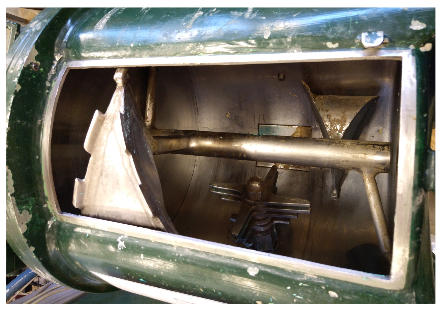
For the gluing of wood particles during particleboard production in laboratory scale a resonating mixer is used; see
Figure 1. The wood particles are lying at the bottom of the mixer and are forced to move by mixing arms. From the top of the mixer the adhesive is sprayed onto the moving wood particles.
2.2. Mathematical Model
In this section the mathematical model for the gluing of wood particles in two dimensions is presented. A more detailed description of the gluing model can be found in [
18]. The cross section of the resonating mixer that is orthogonal to the longitudinal axis is used as state space. The model is based on a lattice gas cellular automaton; see [
20,
21,
22,
23,
24,
25,
26,
27]. The used lattice gas cellular automaton has a triangular lattice and is called FHP lattice gas cellular automaton, named after Frisch, Hasslacher and Pomeau. The FHP lattice gas cellular automaton is defined by a lattice
L, which represents a spatial discretisation, including directions called lattice vectors
,
; states
,
; and an operator called evolution
.
At each node of the lattice there are seven cells which represent the possible directions of movement, the lattice vectors. The lattice vectors , , are limited to the six directions defined by the triangular lattice, and additionally, a stationary lattice vector () is used. The state means that a cell is not occupied, whereas means that it is occupied.
According to literature (e.g., [
23,
27]), the evolution is time-dependent and consists of two parts:
Collision:
During collision all wood particles and adhesive droplets located at the same node influence each other according to the three types of collisions given below. The collision operator
is working locally for each element
by using
whereby
is depending on the used version of the FHP lattice gas cellular automaton.
Streaming:
During streaming the wood particles and adhesive droplets move from their actual location to a specific node based on the corresponding lattice vector. The streaming operator
is defined by
In the following, the evolution operator (
) is defined as composition of collision and streaming
where the evolution is used for updating the states of all
at time tep
t by
For the gluing model of the lattice, the discretisation of the state space is used. The movement of the wood particles is according to the streaming of the lattice gas cellular automaton. Due to the size of a wood particle, it covers a certain number of nodes. Within the evolution, the corresponding states are not independent of each other. The adhesive droplets are moving according to a random walk; see [
28,
29]. Therefore the random walk is added as additional step in the evolution. As the adhesive droplets are forced to move downwards, within the random walk, not every direction is possible.
As wood particles and adhesive droplets have different behaviours, the collision rules of the FHP lattice gas cellular automata have to be changed. For this gluing model three types of collisions are possible:
Collision of adhesive droplets: The collision of adhesive droplets is assumed to be a perfectly inelastic collision.
Collision of wood particles and adhesive droplets: If an adhesive droplet collides with a wood particle it sticks to the surface of the wood particle, whereby penetration and spreading take place. Based on experimental results, of the adhesive mass penetrates into the wood particle. Contact angle measurements using the “Drop Shape Analyzer-DSA30” (KRÜSS GmbH, Hamburg, Germany), indicated a value of for spreading. In the model the diameter of the adhesive is increased by the immediately after the adhesive droplet hits the surface of the wood particle. As a simplification a further spreading of the adhesive droplet does not take place.
Collision of wood particles: Due to the size of the wood particles an arbitrary number of wood particles can be involved in a single collision. Thus, the collision is getting more complex. As a simplification, the velocities of the wood particles are swapped. Within this collision it is possible that adhesive is transferred from one wood particle to another one. This behaviour is called transfer of adhesive. Based on preliminary measurements, at the first contact , at the second contact , and from the third contact onwards are transferred.
After the collision part, the streaming which is the second part of the evolution is executed. Within this step the wood particles and adhesive droplets are moving across the underlying lattice.
The mixing arm forces the wood particles to move. For simplification, the mixing arm has no interaction with the adhesive droplets. If an adhesive droplet hits the wall of the mixer, it sticks onto the wall until it is picked up by a wood particle. When the wood particles hit the bottom they are becoming stationary and can be transported upwards again by the mixing arm (stimulation of wood particles). Additionally, to incorporate gravity a falling area is introduced where the wood particles are moving downwards if they reach a specific height.
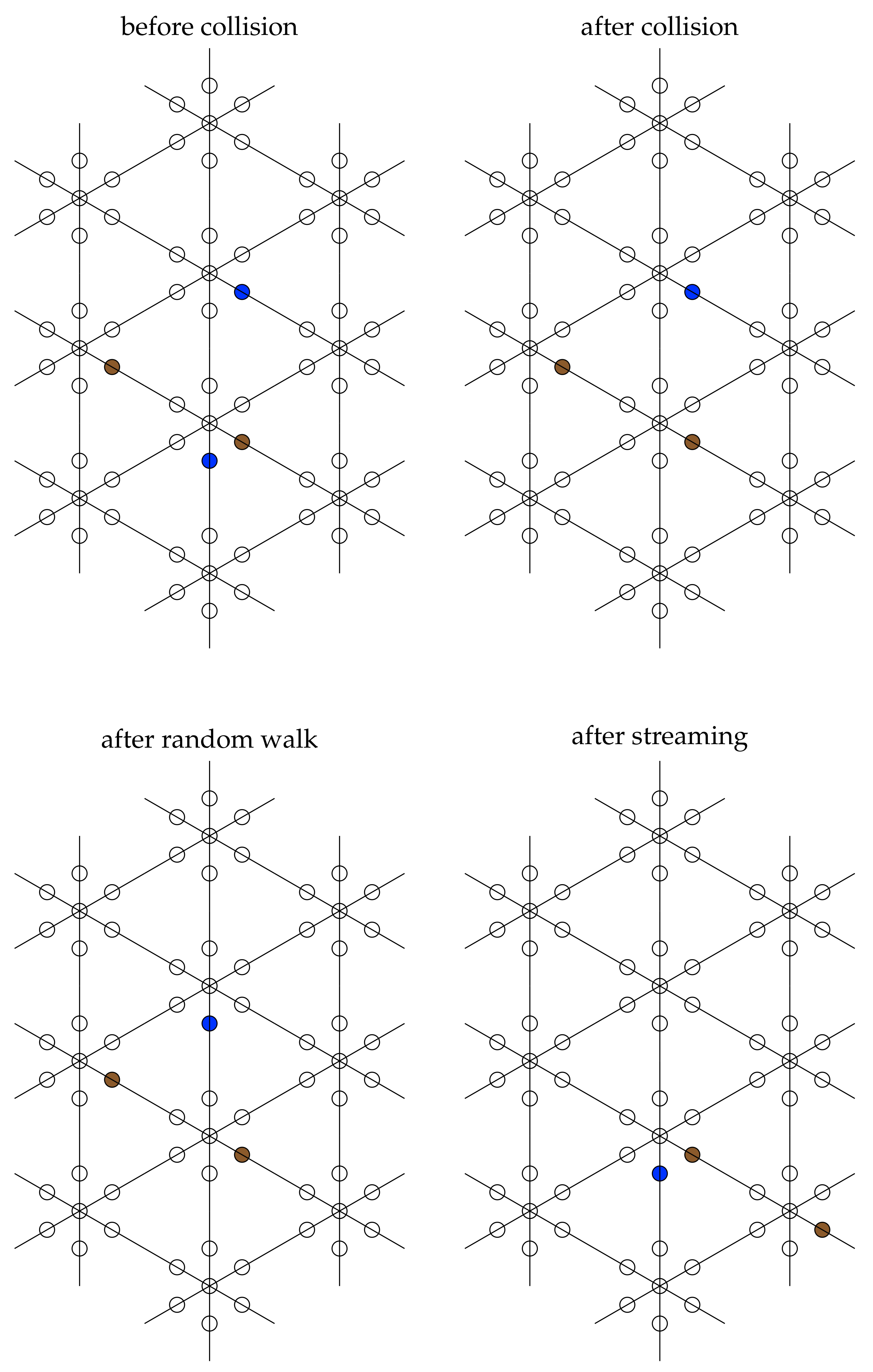
The evolution of the gluing model is shown in
Figure 2 whereby not the whole lattice is depicted. There is one wood particle (shown in brown) and it collides with an adhesive droplet (shown in blue). After collision this adhesive droplet sticks onto the wood particle. The other adhesive droplet is moving according to the random walk. As a last step the wood particle and adhesive droplet move during the streaming.
2.3. Scenarios
The model was implemented in MATLAB R2018b (The MathWorks, Inc., Natick, MA, USA). For the investigation of the research questions, simulations of different scenarios were carried out. Due to the fact that the presented model is a simplification of the real process, some assumptions are necessary.
In the following, the general assumptions for all scenarios are presented. The lattice has a grid width of
cm and covers a diameter of 40 cm. The simulation time is 120 s. The general properties for the wood particles and the total mass of wood are given in
Table 1 (for scenario 1, initial position and initial velocity differ). As stated in
Section 2.1, softwoods are mainly used for particleboard production. Therefore, a typical value for the raw density of spruce, which is a common softwood species, is used. The general properties for the adhesive droplets and the total mass of adhesive are given in
Table 2. The amount of adhesive applied was
(g of solid adhesive to g of absolute dry wood) in the underlying recipe the simulations were based on.
The total masses of wood and adhesive, respectively, were used to estimate the numbers of wood particles and adhesive droplets in the different scenarios. Due to the simplification caused by transforming real values into a spatially discretised two-dimensional model, the mass is not considered in the key figures for comparing different scenarios.
The time step for the simulation is given by the minimum of the time steps for wood particles and adhesive droplets; i.e., it is
s. In
Table 3 the parameters for the mixing arm are given. As the scenarios describe different behaviours, some parameters need to be changed for each scenario.
2.3.1. Scenario 1—Most Simplified
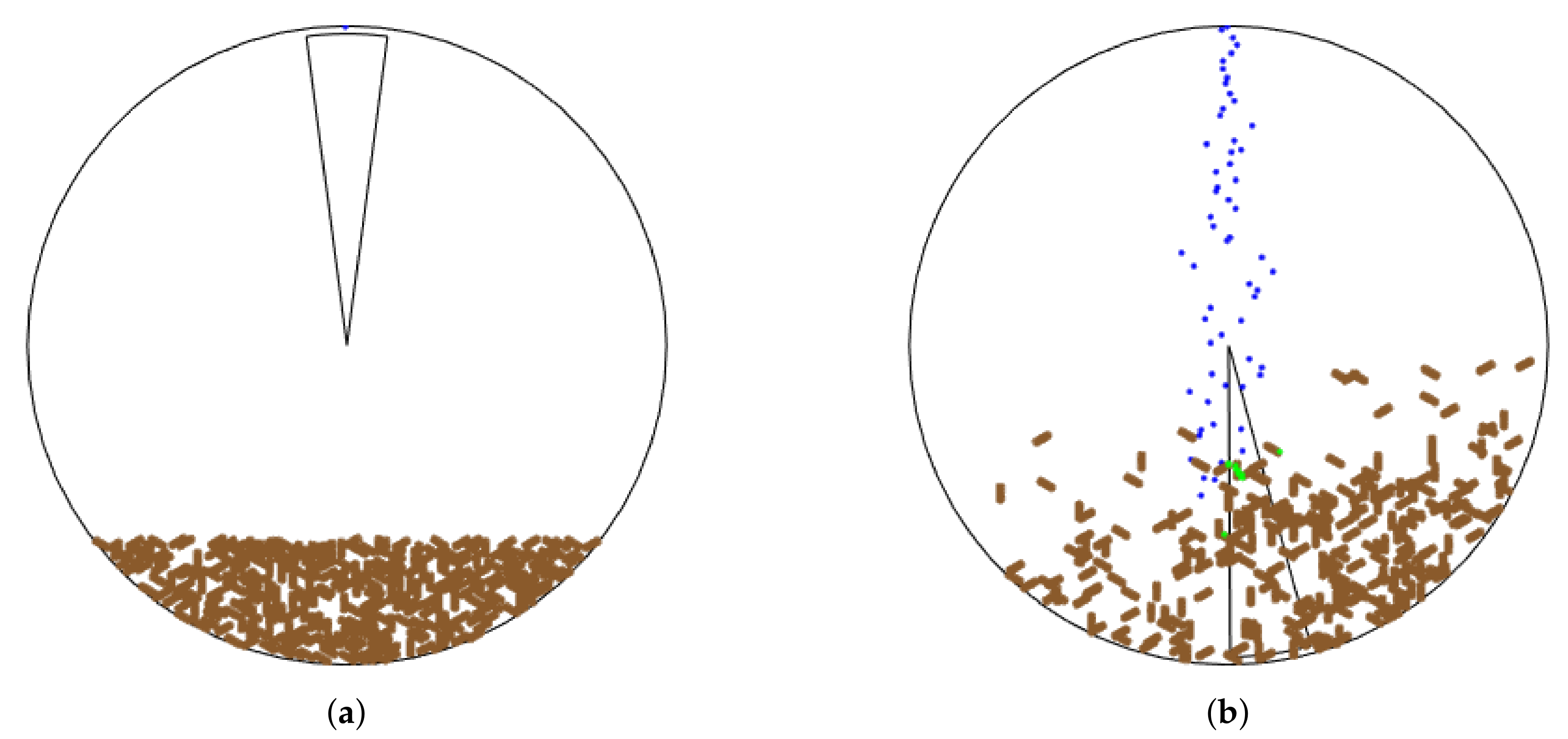
Scenario 1 has the highest level of simplification. Within this scenario, no mixing arm is considered. The properties for each wood particle and the number of wood particles are given in
Table 4. As described in the general assumptions, the initial position and the initial velocity are different from the general assumptions and are chosen randomly for scenario 1. Due to the fact that no mixing arm is implemented in this scenario, there is no force that stimulates the wood particles when they are stationary. Thus, the wood particles are not becoming stationary when they hit the bottom. The initial properties for each adhesive droplet and the number of adhesive droplets are given in
Table 5.
2.3.2. Scenario 2—Mixing Arm
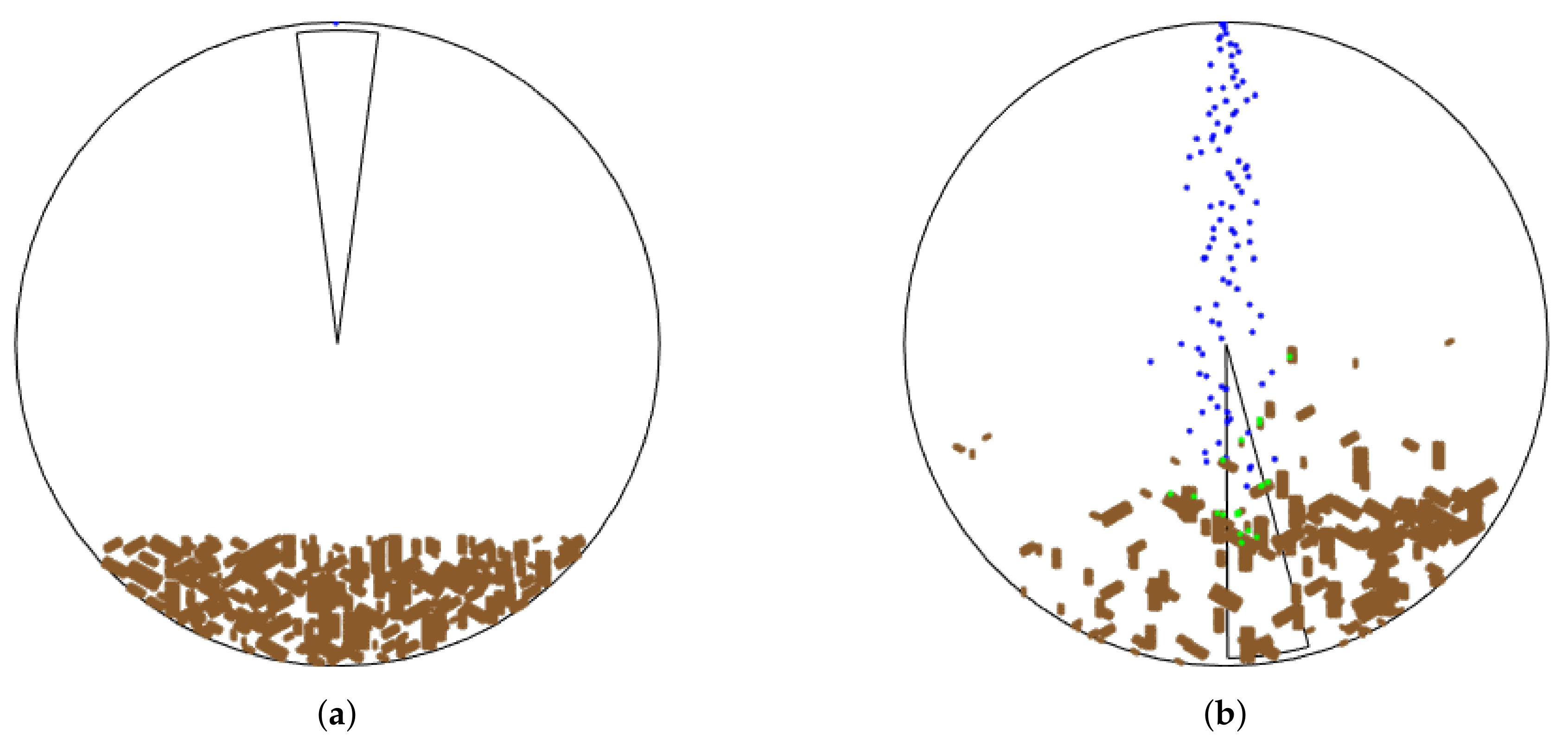
In this scenario a mixing arm with the properties given in
Table 3 is included. The properties for the wood particles and adhesive droplets are given by scenario 1 except for the initial position and initial velocity that are given by the general assumptions.
2.3.3. Scenario 3—Realistic Size Distributions
To include the different sizes of wood particles and adhesive droplets, realistic size distributions for wood particles and adhesive droplets, respectively, are used. The reason for changing more than one parameter was that not the influence of a certain parameter but the overall effect of parameter variations was studied. Unless otherwise stated, for scenario 3 the parameter values are given by scenario 2.
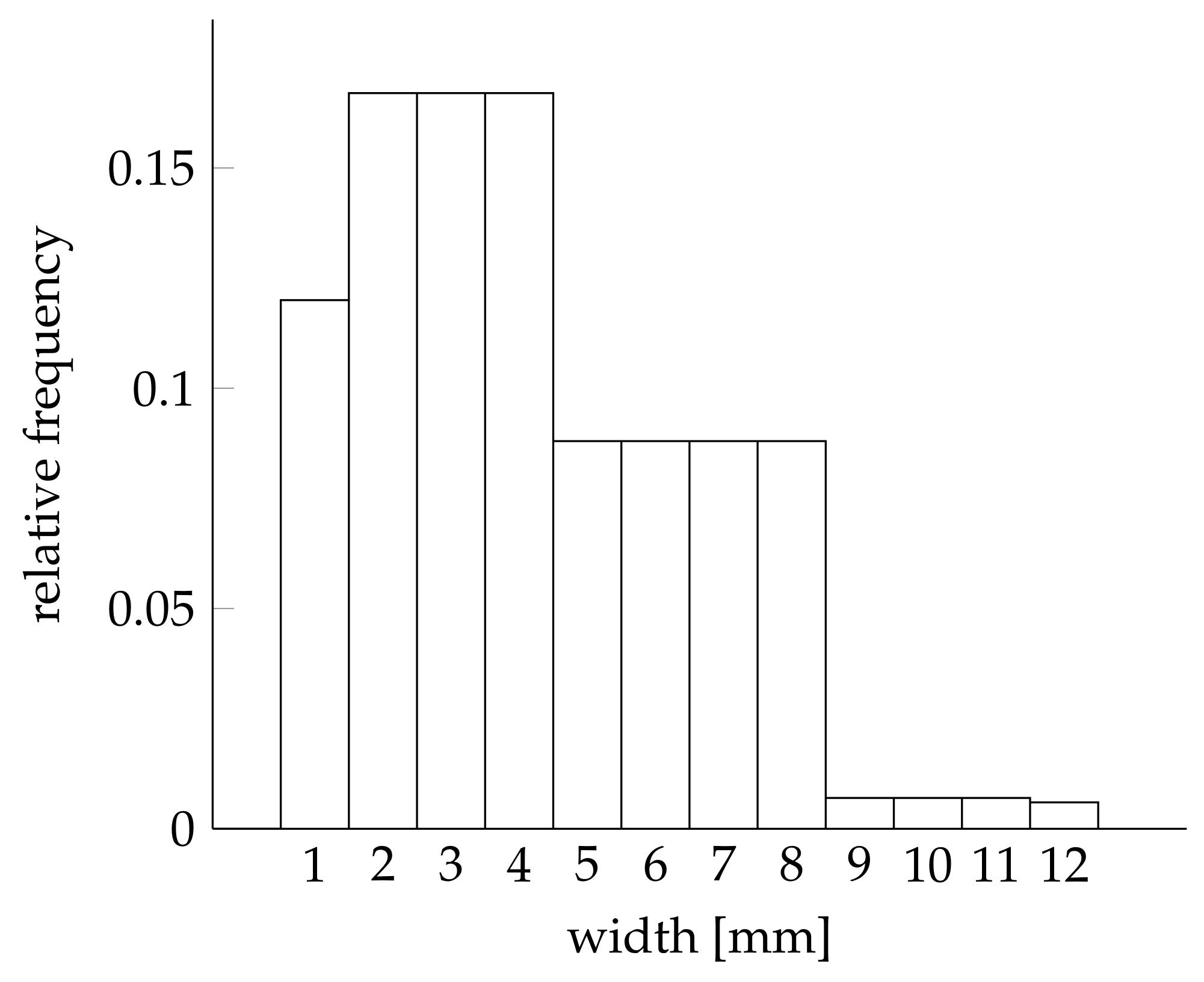
The realistic size distribution for the width of the wood particles is based on a screening curve of spruce wood particles; see
Figure 3.
For a realistic length of the wood particles, the distribution of the width from the screening curve and a length/width ratio are used. Thus, the length is a calculated value. The length/width ratio was measured using CAMSIZER (Microtrac Retsch GmbH, Haan, Germany), and the resulting length/width ratios are between 2 and 3. Using these measured values, the majority of wood particles in scenario 3 are bigger than in scenario 2. This leads to a smaller number of wood particles in scenario 3. Due to the fact that the size distribution of the wood particles is a random sample, the number of wood particles is not the same for every simulation run of this scenario. For the results presented in this paper, the number of wood particles for scenario 3 was 156.
Based on [
5,
15,
30] the diameter of the adhesive droplets is assumed to be normally distributed with
m and
m. Based on this distribution, the mean diameter of the adhesive droplets in scenario 3 is smaller than in scenario 2. This leads to a higher number of adhesive droplets in scenario 3. Again, the number of adhesive droplets changes between simulation runs. The number of adhesive droplets for the simulation of scenario 3 used in this paper was 25,470.
2.3.4. Scenario 4—No Transfer of Adhesive
Within scenario 4 the effect of the transfer of adhesive from one wood particle to other wood particles is investigated. In scenario 4 no adhesive is allowed to be transferred during the collision of wood particles. The transfer of adhesive is set to from the first contact on. The other parameters are the same as in scenario 3. In itself, scenario 4 is not related to practice but by comparing the results of scenario 3 and 4 the effect of the transfer of adhesive can be determined. As mentioned in the description of scenario 3, the number of wood particles and adhesive droplets changes between of simulation runs. For the simulation of scenario 4, 155 wood particles and 25,448 adhesive droplets were used.
2.3.5. Scenario 5—Variation Total Mass of Adhesive
In scenario 5 simulations with , , , , and of the total mass of adhesive used in scenario 3 were executed. The other parameters are the same as in scenario 3.
4. Discussions
Table 7 gives an overview of the presented key figures for the scenarios 1–4. As scenario 5 is a parameter study and stands for itself, it is omitted in this table.
For the investigation of the impacts of different parameters on the adhesive distribution among wood particles, the selected scenarios are used. In the following, the qualitative results of the simulation results are discussed.
Effect of the mixing arm—a comparison of scenarios 1 and 2:
The number of collisions of wood particles in scenario 1 is about lower than in scenario 2. This can be attributed to the different initial distributions of the wood particles and to the effect of the mixing arm. The other results of the two scenarios are similar. Scenario 2 is more realistic than scenario 1 due to the inclusion of the mixing arm.
Effect of realistic size distributions—a comparison pf scenarios 2 and 3:
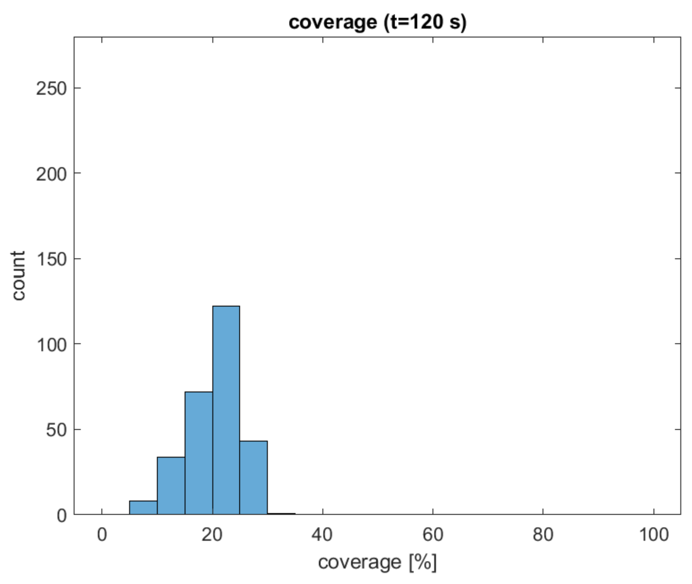
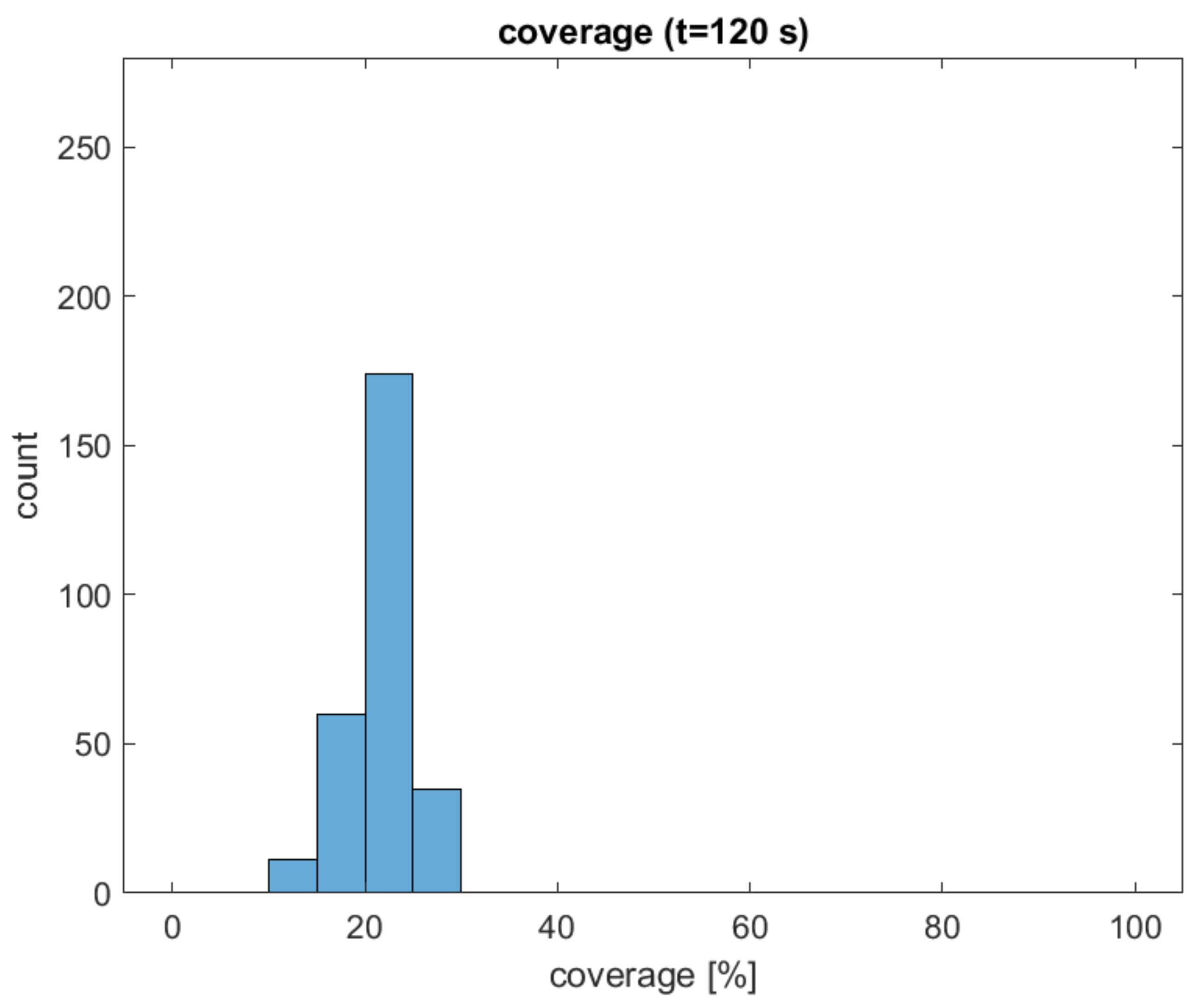
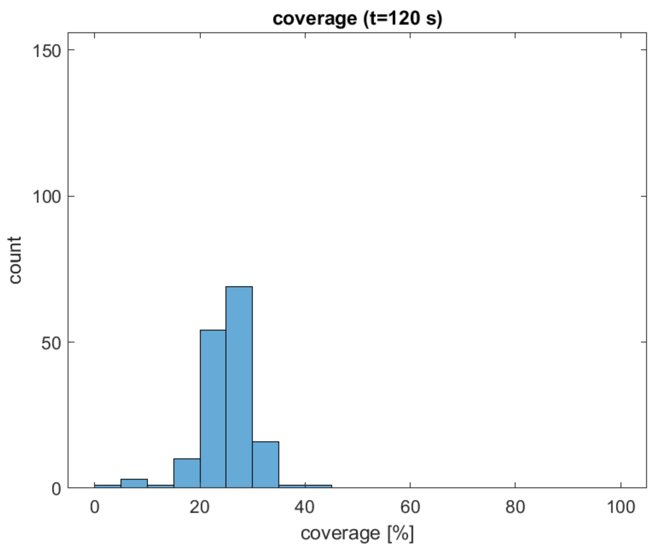
Due to realistic size distributions of wood particles and adhesive droplets, the numbers of wood particles and adhesive droplets changed as well. In scenario 2 the number of wood particles is higher than in scenario 3, whereas in scenario 3 the number of adhesive droplets is higher than in scenario 2. On the one hand there are more collisions of wood particles in scenario 2, but on the other hand there are more collisions with transfer of adhesive and collisions of wood particles and adhesive droplets in scenario 3. Consequently, the mean coverage at the end of the simulation (scenario 2: , scenario 3: ) is higher in scenario 3. This could be explained by the higher ratio of the number of adhesive droplets to the number of wood particles in scenario 3. The realistic size distributions result in a more diverse distribution of coverage. On the one hand, small wood particles have lesser surface areas, which can result in high coverage values. On the other hand, low coverage values can originate from small adhesive droplets. Due to the realistic size distribution of the adhesive droplets, the distribution of the diameter of adhesive areas on the surface of wood particles is becoming more diverse.
Effect of transfer of adhesive—a comparison of scenarios 3 and 4:
At about s (scenario 3) and at s (scenario 4) the relative frequency of wood particles with at least one adhesive droplet reach . These results indicate that the transfer of adhesive increases the efficiency of gluing by about one third. Based on the presented key figure, it is indicated that the transfer of adhesive affects the distribution of the adhesive across the surface of the wood particles.
Effect of total mass of adhesive—scenario 5:
The percentage of the total mass of adhesive and the mean coverage at the end of the simulation are considered for the evaluation of this effect. The results suggest a linear correlation between the total mass of adhesive and the mean coverage () whereby underlying is a small sample size. The relatively small differences in the coverage values might be explained by the assumption that if less adhesive is used, the chance that an adhesive droplet lands on another adhesive droplet that is already present on the wood particle is lower. Additionally, if new adhesive appears to be applied to a position of the wood particle where some adhesive has already been applied, the coverage will only increase if the resulting sum of adhesive leads to a spreading of the adhesive that is higher than the former adhesive area.
Comparison with experimental results:
In [
10] experiments regarding the detection of adhesive on the surface of wood particles were carried out. In these experiments the amount of adhesive applied was
and
(g of solid adhesive to g of absolute dry wood). The glued wood particles were stained using a fluorescent dye and afterwards, the wood particles were viewed under a microscope. The resulting images were used for determination of the coverage. The mean coverage was about
and the standard deviation was about
for an amount of applied adhesive of
. For an amount of applied adhesive of
the mean coverage was about
and the standard deviation was about
. In scenario 3 the mean coverage is about
and the standard deviation is about
(amount of applied adhesive of
in the underlying recipe). The mean coverage of the simulation is about three times higher compared to the experimental results, which can be explained by taken assumptions within the simulation but also by limitations of the experimental setup. Future work will focus, among other things, on the adjustment of assumed parameters for the model, which should lead to more comparable results.
Applicability to industrial conditions:
Conventional industrial resonating mixers have in contrast to laboratory resonating mixers a hollow shaft and mixing arms that rotate up to 10 times faster. To apply the presented model to such industrial processing conditions, three main adaptations would be needed for the model. First, the hollow shaft would be implemented as an inner circle to prevent particles from moving towards the centre of the mixer. Second, the speed of the mixing arms would be increased to, e.g., 10 (1/s). This increase in rotation speed would force the particles to move in the outer ring of the mixer in the direction of rotation. Third, the higher rotation speed of the mixing arms would induce a smaller time step of the simulation, which extends computational time. Such adaptations are subject to future research as the present study focused on the feasibility of lattice gas cellular automata and random walk to describe the gluing of wood particles in general.
