Article

The Generalized H-Bézier Model: Geometric Continuity Conditions and Applications to Curve and Surface Modeling

1
College of Mathematics and Computer Application, Shangluo University, Shangluo 726000, China
2
Department of Applied Mathematics, Xi’an University of Technology, Xi’an 710048, China
3
Department of Mathematics, University of Sargodha, Sargodha 40100, Pakistan
4
Department of Mechanical Engineering, Shizuoka University, Hamamatsu 432, Japan
*
Authors to whom correspondence should be addressed.
Mathematics 2020, 8(6), 924; https://doi.org/10.3390/math8060924
Submission received: 24 April 2020 / Revised: 25 May 2020 / Accepted: 3 June 2020 / Published: 5 June 2020
(This article belongs to the Special Issue Modern Geometric Modeling: Theory and Applications)

Abstract

:
The local controlled generalized H-Bézier model is one of the most useful tools for shape designs and geometric representations in computer-aided geometric design (CAGD), which is owed to its good geometric properties, e.g., symmetry and shape adjustable property. In this paper, some geometric continuity conditions for the generalized cubic H-Bézier model are studied for the purpose of constructing shape-controlled complex curves and surfaces in engineering. Firstly, based on the linear independence of generalized H-Bézier basis functions (GHBF), the conditions of first-order and second-order geometric continuity (namely, G1 and G2 continuity) between two adjacent generalized cubic H-Bézier curves are proposed. Furthermore, following analysis of the terminal properties of GHBF, the conditions of G1 geometric continuity between two adjacent generalized H-Bézier surfaces are derived and then simplified by choosing appropriate shape parameters. Finally, two operable procedures of smooth continuity for the generalized H-Bézier model are devised. Modeling examples show that the smooth continuity technology of the generalized H-Bézier model can improve the efficiency of computer design for complex curve and surface models.

1. Introduction

Parametric curves and surfaces are the main tools used to describe the geometric shape of products in computer-aided geometric design (CAGD), and their related theories and technologies are also the bases and core contents of the whole CAGD [1,2]. Traditional Bézier curves and surfaces are parametric curves and surfaces constructed from Bernstein basis functions. They are not only an important method for representing complex curves and surfaces in the field of CAGD, but also a powerful tool for shape designs and geometric representations of various products [3,4]. However, the Bézier model has some limitations: (i) the shape of the Bézier model is only determined by its control points; and (ii) the Bézier model cannot accurately represent conic curves and surfaces [5]. To overcome these limitations, the shapes of the rational Bézier model and non-uniform rational B-spline (NURBS) with fixed control points can be modified by altering the weight factor [1]. The rational Bézier model and NURBS can accurately express circles and ellipses, but they cannot precisely describe transcendental curves such as hyperbolic curves, catenary curves, and so on [3]. In order to preserve the good properties of the classical Bézier model and enhance its shape adjustability, scholars have recently constructed many curves and surfaces with shape parameters [2,3,4,5,6,7,8,9,10,11,12,13,14,15,16,17,18,19,20,21,22].
The H-Bézier model with shape parameters in algebraic hyperbolic hybrid space maintains the advantages of the Bézier model and can also be used to accurately represent hyperbolic and catenary curves [2,9,10,11,12,13,14,15,16,17,18,19,20,21,22]. In 1993, Pottmann [9] constructed a basis set in algebraic hyperbolic space { 1 ,   t ,   s i n h t ,   c o s h t } For the first time and defined the famous H-Bézier curves using this basis set. A cubic H-Bézier curve is defined as [9]
C ( t ;   α ) = i = 0 3 z i , 3 ( t ;   α )   P i ,   0 t α ,   α > 0
where α is the shape parameter, P 0 ,   P 1 ,   P 2 ,   P 3 are the control points of cubic H-Bézier curves, and z i , 3 ( t )   ( i = 0 , 1 , 2 , 3 ) are the basis functions of the cubic H-Bézier curves, defined as follows:
{ z 0 , 3 ( t ;   α ) = ( α t ) s i n h ( α t ) α s i n h α ,   z 3 , 3 ( t ;   α ) = t s i n h t α s i n h α , z 1 , 3 ( t ;   α ) = M [ α c o s h α t c o s h α s i n h α + s i n h t ) α c o s h α s i n h α z 0 , 3 ( t ;   α ) ] , z 2 , 3 ( t ;   α ) = M [ s i n h ( α t ) + t c o s h α s i n h α ) α c o s h α s i n h α z 3 , 3 ( t ;   α ) ]
where M = α cos h α sin h α α cos h α + α 2 sin h α . The basis functions (2) of cubic H-Bézier curves also satisfy some important properties, such as non-negativity, partition of unity, and symmetry. In 2005, Li and Wang [10] extended the definition of cubic H-Bézier curves to nth-degree curves. They constructed a normative basis set in algebraic hyperbolic hybrid space Γ n = s p a n { 1 ,   t ,   , t n 2 , sin h t ,   cos h t } ( n 2 ) and defined the H-Bézier curves of degree n using this function basis set. The H-Bézier model not only represents hyperbola and catenary curves accurately, but can also adjust its shape without modifying the coordinates of control points.
In view of the remarkable advantages of the H-Bézier model, scholars have done much research on the related theories and applications of the H-Bézier model in recent years. Wang and Yang [11] presented a characterization diagram of the planar cubic H-Bézier model and studied the existence conditions of singularities and inflection points. Qian and Tang [12] investigated the sufficient and necessary conditions for continuity of curvature and tangency between H-Bézier curves of order 4. Fan and Wang [13] presented the matrix representation of the H-Bézier basis and the H-B-spline basis using recursion. Wu [14] analyzed the geometric characteristics of the cubic H-Bézier model, e.g., convexity, singularities, and inflection points. Zhao and Wang [15] proposed a geometric characterization of the H-Bézier model and then compared the singularities of the Bézier, C-Bézier, and H-Bézier models. Wang et al. [16] proposed an effective algorithm of approximate reduction for H-Bézier curves based on generalized inverse matrix theory. Qin et al. [17] constructed the PHH-Bézier curve and proposed sufficient and necessary conditions for a cubic H-Bézier curve to be a PH curve. In [18], Lee and Ahn obtained the limit curves of nth-degree H-Bézier curves as α . Cao et al. [19] proposed two algorithms for the approximation of the respective offset curves of H-Bézier and H-B-spline spline curves. Huang and Wang [20] presented a novel orthogonal basis in hyperbolic hybrid polynomial space which retains prominent characteristics of the H-Bézier basis. Zhang et al. [21] proposed a novel method for unifying C-curves and H-curves by extending the calculation to complex numbers. As is well known, the global shape of the H-Bézier model can be altered without modifying the positions of control points. However, the H-Bézier model in [9,10,11,12,13,14,15,16,17,18,19,20,21] has no local shape adjustability due to the lack of local shape parameters. In [22], Hu et al. presented a novel local controlled H-Bézier model called the generalized H-Bézier model. The global and local shapes of the new model can be adjusted by changing its local shape parameters while the control points are maintained. Compared with the H-Bézier model, the generalized H-Bézier model in [22] has greater advantages and plays a key role in describing complex curves and surfaces. In order to handle the problem of not being able to construct complex curves and surfaces using a single generalized H-Bézier model, in this paper we propose the respective geometric continuity conditions between two adjacent generalized H-Bézier curves and surfaces.
The rest of the paper is organized as follows. The definition and properties of the generalized H-Bézier model are given in Section 2. In Section 3, we propose the geometric continuity conditions for the generalized H-Bézier model and give some examples. Two practical applications are discussed in Section 4, and finally, conclusions are given in Section 5.

2. The Generalized Cubic H-Bézier Model

2.1. Definition of Generalized Cubic H-Bézier Curves

Definition 1.
Let us consider shape parameters α 1 , α 2 , α 3 > 0 ; the functions
{ h 0 , 3 ( t ) = α 1 ( 1 t ) s i n h ( α 1 α 1 t ) α 1 s i n h α 1 , h 1 , 3 ( t ) = α 1 t s i n h α 1 + s i n h ( α 1 α 1 t ) α 1 s i n h α 1 α 2 t c o s h α 2 + s i n h ( α 2 α 2 t ) s i n h α 2 s i n h ( α 2 t ) + α 2 t α 2 c o s h α 2 2 s i n h α 2 + α 2 , h 2 , 3 ( t ) = α 2 t c o s h α 2 + s i n h ( α 2 α 2 t ) s i n h α 2 s i n h ( α 2 t ) + α 2 t α 2 c o s h α 2 2 s i n h α 2 + α 2 α 3 t s i n h ( α 3 t ) α 3 s i n h α 3 , h 3 , 3 ( t ) = α 3 t s i n h ( α 3 t ) α 3 s i n h α 3
in terms of variable t [ 0 , 1 ] are then called the generalized cubic H-Bézier basis functions [22].
Remark 1.
If the shape parameters are such that α 1 = α 2 = α 3 = α , then the basis functions h i , 3 ( t )   ( i = 0 , 1 , 2 , 3 ) are just the classical cubic H-Bézier basis defined by (2). It can be proved that the basis functions h i , 3 ( t )   ( i = 0 , 1 , 2 , 3 ) in (3) have many properties similar to those of the classical cubic H-Bézier basis functions, such as non-negativity, symmetry, etc. (see Theorem 1 in [22]).
Figure 1 shows a graphical representation of the basis functions h i , 3 ( t )   ( i = 0 , 1 , 2 , 3 ) in (3) with variation of the shape parameters. One can see from Figure 1 that modification of the three shape parameters has a distinct effect on the basis functions h i , 3 ( t )   ( i = 0 , 1 , 2 , 3 ) .
Theorem 1.
The basis functions h i , 3 ( t )   ( i = 0 , 1 , 2 , 3 ) possess the following terminal properties:
{ h 0 , 3 ( 0 ) = h 3 , 3 ( 1 ) = 1 ,   h i , 3 ( 0 ) = h j , 3 ( 1 ) = 0 ,   i = 1 , 2 , 3 ;   j = 0 , 1 , 2 ; h 0 , 3 ( 1 ) ( 0 ) = h 1 , 3 ( 1 ) ( 0 ) = α 1 ( c o s h α 1 1 ) α 1 s i n h α 1 , h i , 3 ( 1 ) ( 0 ) = h j , 3 ( 1 ) ( 1 ) = 0   ( i = 2 , 3 ;   j = 0 , 1 ) , h 3 , 3 ( 1 ) ( 1 ) = h 2 , 3 ( 1 ) ( 1 ) = α 3 ( 1 c o s h α 3 ) α 3 s i n h α 3 ; h 0 , 3 ( 2 ) ( 0 ) = α 1 2 s i n h α 1 α 1 s i n h α 1 ,   h 1 , 3 ( 2 ) ( 0 ) = α 1 2 s i n h α 1 α 1 s i n h α 1 α 2 2 s i n h α 2 α 2 c o s h α 2 2 s i n h α 2 + α 2 , h 2 , 3 ( 2 ) ( 0 ) = α 2 2 s i n h α 2 α 2 c o s h α 2 2 s i n h α 2 + α 2 ,   h 3 , 3 ( 2 ) ( 0 ) = 0 , h 0 , 3 ( 2 ) ( 1 ) = 0 ,   h 1 , 3 ( 2 ) ( 1 ) = α 2 2 s i n h α 2 α 2 c o s h α 2 2 s i n h α 2 + α 2 , h 2 , 3 ( 2 ) ( 1 ) = α 3 2 s i n h α 3 α 3 s i n h α 3 α 2 2 s i n h α 2 α 2 c o s h α 2 2 s i n h α 2 + α 2 ,   h 3 , 3 ( 2 ) ( 1 ) = α 3 2 s i n h α 3 α 3 s i n h α 3 .
Proof. 
These results follow obviously from Definition 1. □
Definition 2.
For given control points P i R u   ( u = 2 , 3 ;   i = 0 , 1 , 2 , 3 ) , a generalized cubic H-Bézier curve
H ( t ; Ω ) = i = 0 3 P i h i , 3 ( t ) ,   t [ 0 , 1 ] ,
can be defined as follows [22], where Ω = { α 1 , α 2 , α 3 } are local shape parameters and h i , 3 ( t )   ( i = 0 , 1 , 2 , 3 ) are the generalized cubic H-Bézier basis functions defined by (3).
Remark 2.
It follows from (3) that the curves in (5) inherit many excellent properties of the cubic H-Bézier curves in (1), such as symmetry, the convex hull property, etc. (see Theorem 2 in [22]). In particular, when α 1 = α 2 = α 3 = α , the curves H ( t ; Ω ) in (5) degenerate to traditional cubic H-Bézier curves.
Theorem 2.
The curves H ( t ; Ω ) in (5) have the following terminal properties:
{ H ( 0 ; Ω ) = P 0 , H ( 1 ; Ω ) = P 3 , H ( 0 ; Ω ) = α 1 ( 1 c o s h α 1 ) α 1 s i n h α 1 ( P 1 P 0 ) , H ( 1 ; Ω ) = α 3 ( 1 c o s h α 3 ) α 3 s i n h α 3 ( P 3 P 2 ) , H ( 0 ; Ω ) = α 1 2 s i n h α 1 α 1 s i n h α 1 ( P 1 P 0 ) + α 2 2 s i n h α 2 α 2 c o s h α 2 2 s i n h α 2 + α 2 ( P 2 P 1 ) , H ( 1 ; Ω ) = α 2 2 s i n h α 2 α 2 c o s h α 2 2 s i n h α 2 + α 2 ( P 1 P 2 ) + α 3 2 s i n h α 3 α 3 s i n h α 3 ( P 2 P 3 ) .
Proof. 
According to the terminal properties in (4), as well as the definition of the generalized cubic H-Bézier curves, we can deduce the terminal properties (6) of the curves H ( t ; Ω ) , thus proving Theorem 2. □

2.2. Shape Control of the Generalized Cubic H-Bézier Curves

For t [ 0 , 1 ] , we rewrite (5) as follows:
H ( t ; Ω ) = P 0 + f 1 ( t ; α 1 ) ( P 1 P 0 ) + f 2 ( t ; α 2 ) ( P 2 P 1 ) + f 3 ( t ; α 3 ) ( P 3 P 2 ) ,
in which
{ f 1 ( t ; α 1 ) = α 1 t s i n h α 1 + s i n h ( α 1 α 1 t ) α 1 s i n h α 1 , f 2 ( t ; α 2 ) = α 2 t c o s h α 2 + s i n h ( α 2 α 2 t ) s i n h α 2 s i n h ( α 2 t ) + α 2 t α 2 t c o s h α 2 2 s i n h α 2 + α 2 , f 3 ( t ; α 3 ) = α 3 t s i n h ( α 3 t ) α 3 s i n h α 3 ,
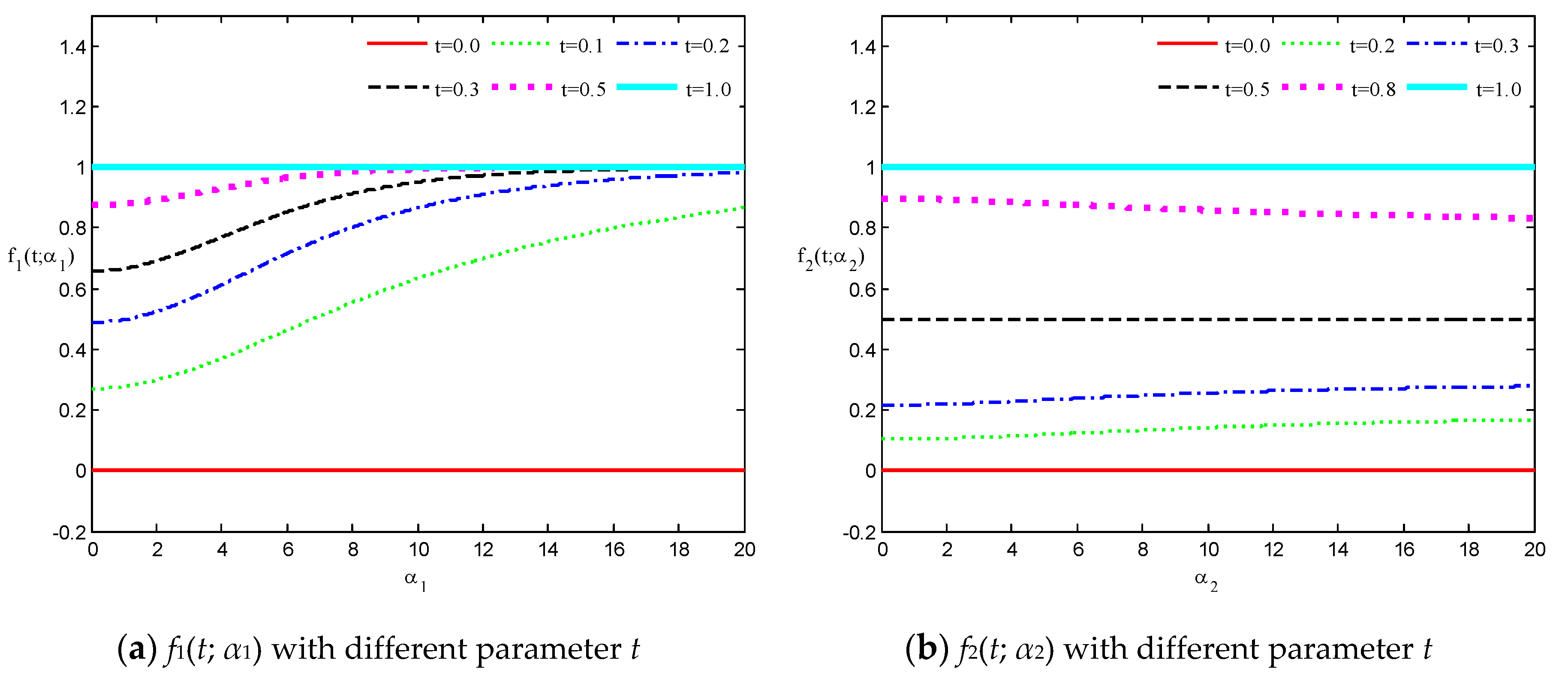
where f i ( t ; α i ) ( i = 1 , 2 , 3 ) are called translational speed functions; see Figure 2.
For a given t ˜ ( 0 , 1 ) and a fixed control polygon, the expression of the curves H ( t ˜ ; Ω ) describes the movement locus of a fixed point H ( t ˜ ) when one of the shape parameters, α i ( i = 1 , 2 , 3 ) , changes.
Afterwards, we obtain the partial derivative of (7) with respect to α i as follows:
H ( t ˜ ; Ω ) α i = { d   f i ( t ˜ ; α i ) d α i ( P i P i 1 )   ( i = 1 , 2 ) , d   f i ( t ˜ ; α i ) d α i ( P i 1 P i )   ( i = 3 ) ,
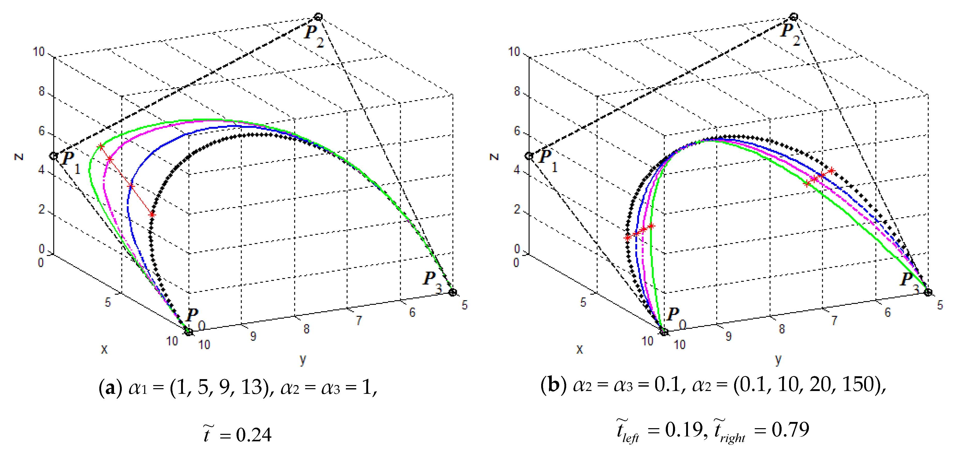
which signifies that the trace curve H ( t ˜ ; Ω ) of a fixed point H ( t ˜ ) is a straight line only when the shape parameter α i changes (as shown in Figure 3).
Obviously, for a fixed control polygon and a given t ˜ ( 0 , 1 ) , the value change of one shape parameter α i ( i = 1 , 2 , 3 ) will result in a linear change of a point H ( t ˜ ) on the curves. For a fixed t ˜ ( 0 , 1 ) , according to (8), we know that
d f 1 ( t ˜ ; α 1 ) d α 1 > 0 .
We can see from (10) that f 1 ( t ˜ ; α 1 ) is an increasing function with α 1 (see Figure 2a), which means that the generalized cubic H-Bézier curve will move along the same direction as P 1 P 0 with increasing α 1 , and vice versa. Analogously, we deduce that the shape parameter α 3 has a similar effect on the edge P 2 P 3 on the basis of the monotonicity principle of f 3 ( t ; α 3 ) (as shown in Figure 2c). Notice, however, that f 2 ( t ; α 2 ) augments or diminishes with increasing α 2 for any fixed t ˜ ( 0 , 0.5 ) or t ˜ ( 0.5 , 1 ) , respectively (as shown in Figure 2b), which signifies that the curves H ( t ; Ω ) defined on intervals (0, 0.5) and (0.5, 1) move in the same and opposite direction as the edge P 2 P 1 as α 2 increases, respectively. From the discussions above, the effect laws of the shape parameters α i ( i = 1 , 2 , 3 ) on generalized cubic H-Bézier curves are obtained under the circumstance of the control points of the curves remaining unchanged.
(a)
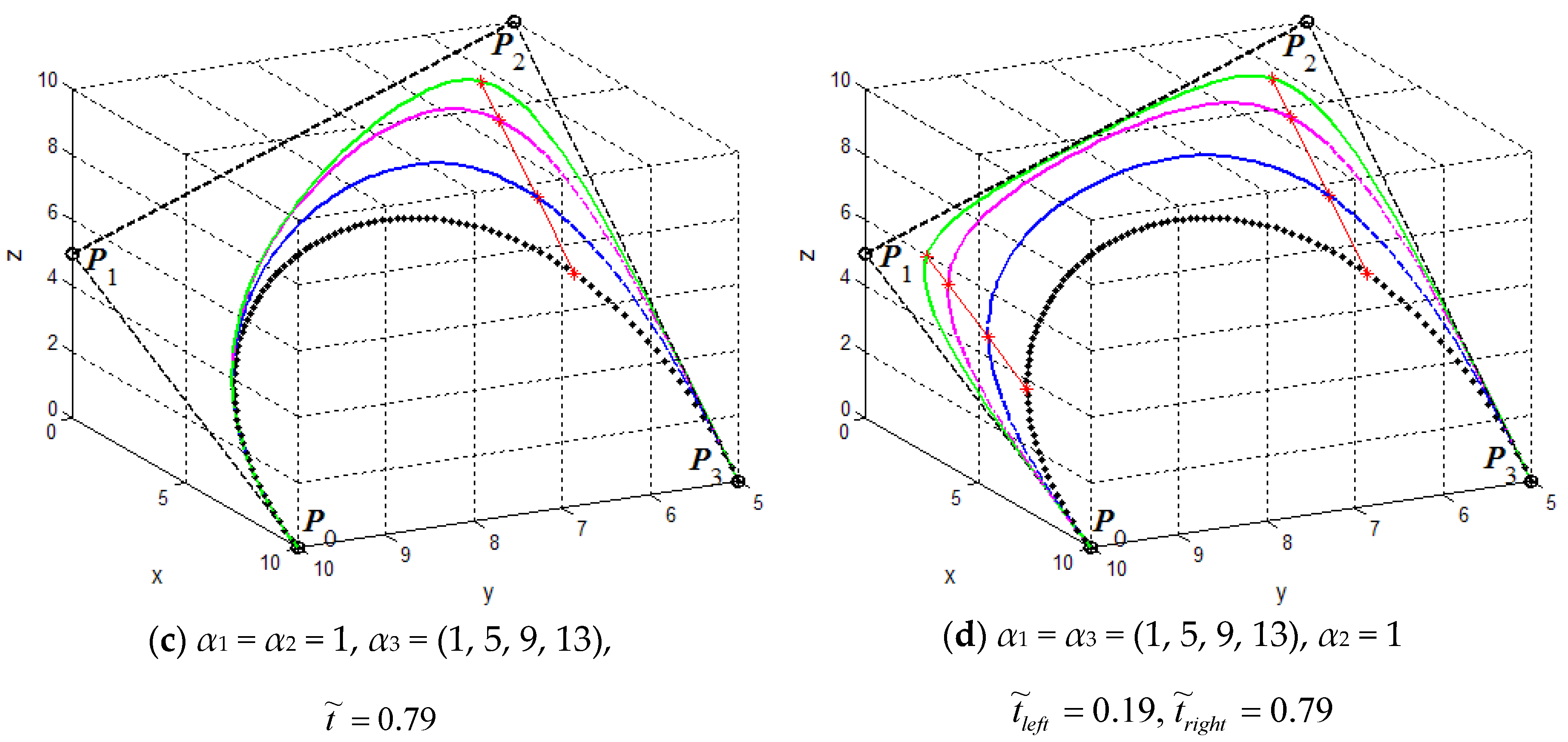
For fixed shape parameters α i ( i = 2 , 3 ) , the curves H ( t ; Ω ) will gradually approach or go far away from the control point P 1 when increasing or decreasing the value of shape parameter α 1 . That means that the shape parameter α 1 is mainly used to adjust the local shape of the curves in the vicinity of control point P 1 (as shown in Figure 3a).
(b)
For fixed shape parameters α 1 and α 3 , the curves H ( t ; Ω ) will simultaneously move away from the control points P 1 and P 2 with increasing value of the shape parameter α 2 (as shown in Figure 3b). What calls for special attention is that the location of point H ( 0.5 ; Ω ) will not change as α 2 increases.
(c)
For fixed shape parameters α 1 and α 2 , the curves H ( t ; Ω ) will get nearer to or farther away from control point P 3 when increasing or decreasing the value of shape parameter α 3 . That means that the shape parameter α 3 is mainly utilized to control the local shape of the curves in the vicinity of control point P 3 (as shown in Figure 3c).
Besides this, the curves H ( t ; Ω ) gradually approach or move away from their control polygon spanned by P i   ( i = 0 , 1 , 2 , 3 ) when increasing or decreasing the values of shape parameters α 1 and α 3 simultaneously (as shown in Figure 3d). In conclusion, we can see expressly that the shape parameters α i ( i = 1 , 2 , 3 ) can act as tension parameters, and their influence rules on the curves H ( t ; Ω ) are perspicuous (see Figure 3).
Figure 3 displays the influences of the three shape parameters on the cubic generalized H-Bézier curves when their control points are fixed. Figure 3a–c shows the curves with two fixed shape parameters while changing α 1 ,   α 2 ,   α 3 , respectively. Figure 3d shows the curves while altering shape parameters α 1 and α 3 simultaneously. The influence rules of the shape parameters on the curves H ( t ; Ω ) can be seen distinctly in Figure 3. Note that, in Figure 3, the values in parentheses show the changes of the shape parameters in the corresponding position, with the values from left to right in parentheses corresponding to the H-Bézier curves from the black dotted curve to the green solid curve in each graph; the red asterisks marked on the different generalized cubic H-Bézier curves in each figure represent the points with the same parameter t ˜ , so that the straight lines connecting these points are the motion trajectory of the points corresponding to t ˜ when altering the shape parameters.

2.3. Definition of Generalized Bicubic H-Bézier Surfaces

Definition 3.
Given a set of control points Q i , j R 3 ( i ,   j = 0 , 1 , 2 , 3 ) , the tensor product parametric surfaces
S ( u , v ; Ω α , Ω β ) = i = 0 3 j = 0 3 h i , 3 ( u ) h j , 3 ( v ) Q i , j ,   0 u , v 1 ,
are called generalized bicubic H-Bézier surfaces with 4 × 4 control mesh points Q i , j , where h i , 3 ( u ) ( i = 0 , 1 , 2 , 3 ) and h j , 3 ( v ) ( j = 0 , 1 , 2 , 3 ) are the generalized cubic H-Bézier basis functions defined in (3); Ω α = { α 1 , α 2 , α 3 } and Ω β = { β 1 , β 2 , β 3 } are local shape parameters for the basis functions h i , 3 ( u ) and h j , 3 ( v ) , respectively.
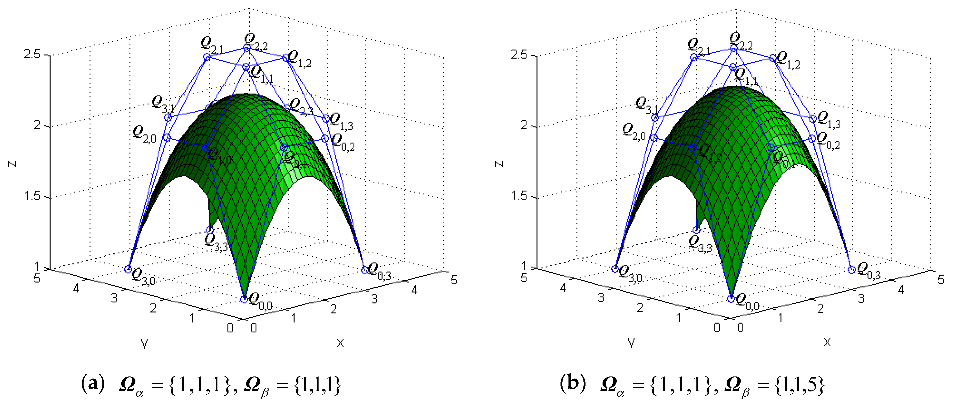
The tensor products of generalized bicubic H-Bézier surfaces have properties similar to those of the tensor products of classical bicubic H-Bézier ones. By keeping the control mesh fixed, the shape of the generalized bicubic H-Bézier surface can also be modified by altering the shape parameters. Figure 4 and Figure 5 show the different behaviors of surfaces S ( u , v ; Ω α , Ω β ) by alteration of the shape parameters in their domain.

3. Geometric Continuity Conditions for the Generalized Cubic H-Bézier Model

In the design of curve and surface modeling, we often encounter some complex curves and surfaces that cannot be represented by a single curve and surface, so the technology of smooth splicing between multiple adjacent curves and surfaces seems to be very important. According to the smooth continuity conditions of parametric curves and surfaces, we will discuss the G1 and G2 continuity conditions for generalized cubic H-Bézier curves and G1 continuity conditions for generalized bicubic H-Bézier surfaces. Since the smooth continuity of surfaces has directionality, there are three different ways for surfaces to achieve smooth continuity at the joint, which are the continuity of the two surfaces in the u direction, the continuity of one surface in the u direction and the other in the v direction, and the continuity of the two surfaces in the v direction. These smooth continuity conditions will be discussed one by one below.

3.1. G1 and G2 Smooth Continuity for Generalized Cubic H-Bézier Curves

For the convenience of our discussion, it is assumed that the expressions of the two generalized cubic H-Bézier curves to be spliced are as follows:
{ H 1 ( t ; Ω 1 ) = i = 0 3 P i 1 h i , 3 ( t ) , H 2 ( t ; Ω 2 ) = i = 0 3 P i 2 h i , 3 ( t ) ,
where Ω 1 = { α 1 , 1 , α 2 , 1 , α 3 , 1 } and Ω 2 = { α 1 , 2 , α 2 , 2 , α 3 , 2 } are the shape parameters of the curves H 1 ( t , Ω 1 ) and H 2 ( t , Ω 2 ) , respectively.
Theorem 3.
For the two adjacent generalized cubic H-Bézier curves defined by (12), the necessary and sufficient conditions of G1 smooth continuity at the joint are as follows:
{ P 0 2 = P 3 1 , P 1 2 = λ α 3 , 1 ( 1 cos h α 3 , 1 ) α 3 , 1 sin h α 3 , 1 α 1 , 2 sin h α 1 , 2 α 1 , 2 ( 1 cos h α 1 , 2 ) ( P 3 1 P 2 1 ) + P 3 1
where λ > 0 is an arbitrary constant.
Proof. 
In order to make two adjacent curves H 1 ( t ; Ω 1 ) and H 2 ( t ; Ω 2 ) reach G1 smooth continuity at the joint, they should satisfy G0 continuity in the first place, which means that the two splicing curves should be connected from end to end:
P 0 2 = H 2 ( 0 ; Ω 2 ) = H 1 ( 1 ; Ω 1 ) = P 3 1 .
At the same time, G1 continuity of the two curves needs to have the same tangent direction at the splicing point [23,24]; that is,
H 2 ( 0 ; Ω 2 ) = λ H 1 ( 1 ; Ω 1 ) ,
where λ > 0 is an arbitrary constant.
According to the terminal properties (6) of generalized cubic H-Bézier curves, we have
{ H 2 ( 0 ; Ω 2 ) = α 1 , 2 ( 1 cos h α 1 , 2 ) α 1 , 2 sin h α 1 , 2 ( P 1 2 P 0 2 ) , H 1 ( 1 ; Ω 1 ) = α 3 , 1 ( 1 cos h α 3 , 1 ) α 3 , 1 sin h α 3 , 1 ( P 3 1 P 2 1 ) .
Substituting (16) into (15) and combining it with (14), we can obtain
P 1 2 = λ α 3 , 1 ( 1 cos h α 3 , 1 ) α 3 , 1 sin h α 3 , 1 α 1 , 2 sin h α 1 , 2 α 1 , 2 ( 1 cos h α 1 , 2 ) ( P 3 1 P 2 1 ) + P 3 1 .
From the above, (14) and (17) constitute G1 smooth continuity conditions for the two adjacent generalized cubic H-Bézier curves. Thus, Theorem 3 is proved. □
Specifically, Equation (13) is the necessary and sufficient condition for C1 smooth continuity of two adjacent generalized cubic Bézier curves when λ = 1.
Theorem 4.
For the two adjacent generalized cubic H-Bézier curves defined by (12), the necessary and sufficient conditions of G2 smooth continuity at the joint are given by
{ P 0 2 = P 3 1 , P 1 2 = λ α 3 , 1 ( 1 cos h α 3 , 1 ) α 3 , 1 sin h α 3 , 1 α 1 , 2 sin h α 1 , 2 α 1 , 2 ( 1 cos h α 1 , 2 ) ( P 3 1 P 2 1 ) + P 3 1 , P 2 2 = λ 2 R S P 1 1 R [ λ 2 ( S + α 3 , 1 2 sin h α 3 , 1 sin h α 3 , 1 α 3 , 1 ) + μ α 3 , 1 ( cos h α 3 , 1 1 ) sin h α 3 , 1 α 3 , 1 + λ α 3 , 1 ( cos h α 3 , 1 1 ) sin h α 3 , 1 α 3 , 1 α 1 , 2 sin h α 1 , 2 α 1 , 2 ( 1 cos h α 1 , 2 ) ( α 1 , 2 2 sin h α 1 , 2 sin h α 1 , 2 α 1 , 2 + 1 R ) ] P 2 1 + R [ λ 2 α 3 , 1 2 sin h α 3 , 1 sin h α 3 , 1 α 3 , 1 + μ α 3 , 1 ( cos h α 3 , 1 1 ) sin h α 3 , 1 α 3 , 1 α 1 , 2 2 sin h α 1 , 2 sin h α 1 , 2 α 1 , 2 + ( α 1 , 2 2 sin h α 1 , 2 sin h α 1 , 2 α 1 , 2 + 1 R ) ( λ α 3 , 1 ( cos h α 3 , 1 1 ) sin h α 3 , 1 α 3 , 1 α 1 , 2 sin h α 1 , 2 α 1 , 2 ( 1 cos h α 1 , 2 ) + 1 ) ] P 3 1 ,
where λ > 0 ,   μ is an arbitrary constant, and
R = α 2 , 2 cos h α 2 , 2 2 sin h α 2 , 2 + α 2 , 2 α 2 , 2 2 sin h α 2 , 2 ,   S = α 2 , 1 2 sin h α 2 , 1 α 2 , 1 cos h α 2 , 1 2 sin h α 2 , 1 + α 2 , 1 .
Proof. 
If the two adjacent generalized cubic H-Bézier curves H 1 ( t ; Ω 1 ) and H 2 ( t ; Ω 2 ) achieve G2 continuity at the joint, they are required to achieve G1 continuity first (as shown in (13)).
Furthermore, G2 continuity of the two adjacent curves also needs to be satisfied [23,24,25]:
H 2 ( 0 ; Ω 2 ) = λ 2 H 1 ( 1 ; Ω 1 ) + μ H 1 ( 1 ; Ω 1 ) ,
where λ > 0, μ is an arbitrary constant.
In terms of the terminal properties (6) of generalized cubic H-Bézier curves, we have
α 1 , 2 2 sin h α 1 , 2 α 1 , 2 sin h α 1 , 2 ( P 1 2 P 0 2 ) + α 2 , 2 2 sin h α 2 , 2 α 2 , 2 cos h α 2 , 2 2 sin h α 2 , 2 + α 2 , 2 ( P 2 2 P 1 2 ) = λ 2 [ α 2 , 1 2 sin h α 2 , 1 α 2 , 1 cos h α 2 , 1 2 sin h α 2 , 1 + α 2 , 1 ( P 1 1 P 2 1 ) + α 3 , 1 2 sin h α 3 , 1 α 3 , 1 sin h α 3 , 1 ( P 2 1 P 3 1 ) ] + μ α 3 , 1 ( 1 cos h α 3 , 1 ) α 3 , 1 sin h α 3 , 1 ( P 3 1 P 2 1 ) .
Finally, the third equation of (18) can be obtained by combining (13) and (20). Thus, Theorem 4 is proved. □
Specifically, Equation (18) is the necessary and sufficient condition for C2 smooth continuity of two adjacent generalized cubic H-Bézier curves when λ = 1, μ = 0.
Remark 3.
While keeping the continuity conditions of G1 and G2 unchanged, we can adjust the global and local shapes of composite generalized cubic H-Bézier curves by modifying the values of shape parameters, which is the advantage of splicing generalized cubic H-Bézier curves.
According to the two smooth continuity conditions of generalized cubic H-Bézier curves discussed above, we take G2 continuity as an example to give a specific splicing algorithm for two adjacent curves. The procedure is shown in Algorithm 1.
Algorithm 1. CurveJoint(Px, Py, A, B, lamda, mu)
{ /* G2 smooth continuity between two adjacent generalized cubic H-Bézier curves */
  /* Input: Px, Py control points of the first curve */
  /*    A, B  shape parameters of the first and second curve, respectively */
  /*    lamda, mu */
  /* Output: composite generalized cubic H-Bézier curves with G2 smooth continuity */
  N = 101;
  Compute the values of the basis function for u and store them in h03[N], h13[N], h23[N], h33[N], respectively;
  for (i = 0; i <= N; ++i)
    {
    Hx[i] = h03[i] * Px[0] + h13[i] * Px[1] + h23[i] * Px[2] + h33[i] * Px[3];
    Hy[i] = h03[i] * Py[0] + h13[i] * Py[1] + h23[i] * Py[2] + h33[i] * Py[3];
    }
  Plot the initial generalized cubic H-Bézier curve according to Hx and Hy;
  Compute the first three control points of the second curve according to (18) and store them in Qx[i] and Qy[i] (i = 0,1,2);
  Give the last control point Qx[3],Qy[3];
  for (i = 0; i <= N; ++i)
  {
    HHx[i] = h03[i] * Qx[0] + h13[i] * Qx[1] + h23[i] * Qx[2] + h33[i] * Qx[3];
    HHy[i] = h03[i] * Qy[0] + h13[i] * Qy[1] + h23[i] * Qy[2] + h33[i] * Qy[3];
  }
  Plot the generalized cubic H-Bézier curve that needs to reach G2 smooth continuity according to HHx and HHy;
}
Remark 4.
According to Algorithm 1, composite generalized cubic H-Bézier curves with G2 continuity can be easily obtained. Similarly, when “the first three control points of the second curve are calculated according to (18)” and the next step “give the last control points” in Algorithm 1 are replaced by “the first two control points of the second curve are calculated in terms of (13)” and “give the remaining two control points”, generalized cubic H-Bézier curves with G1 continuity can be obtained by Algorithm 1.
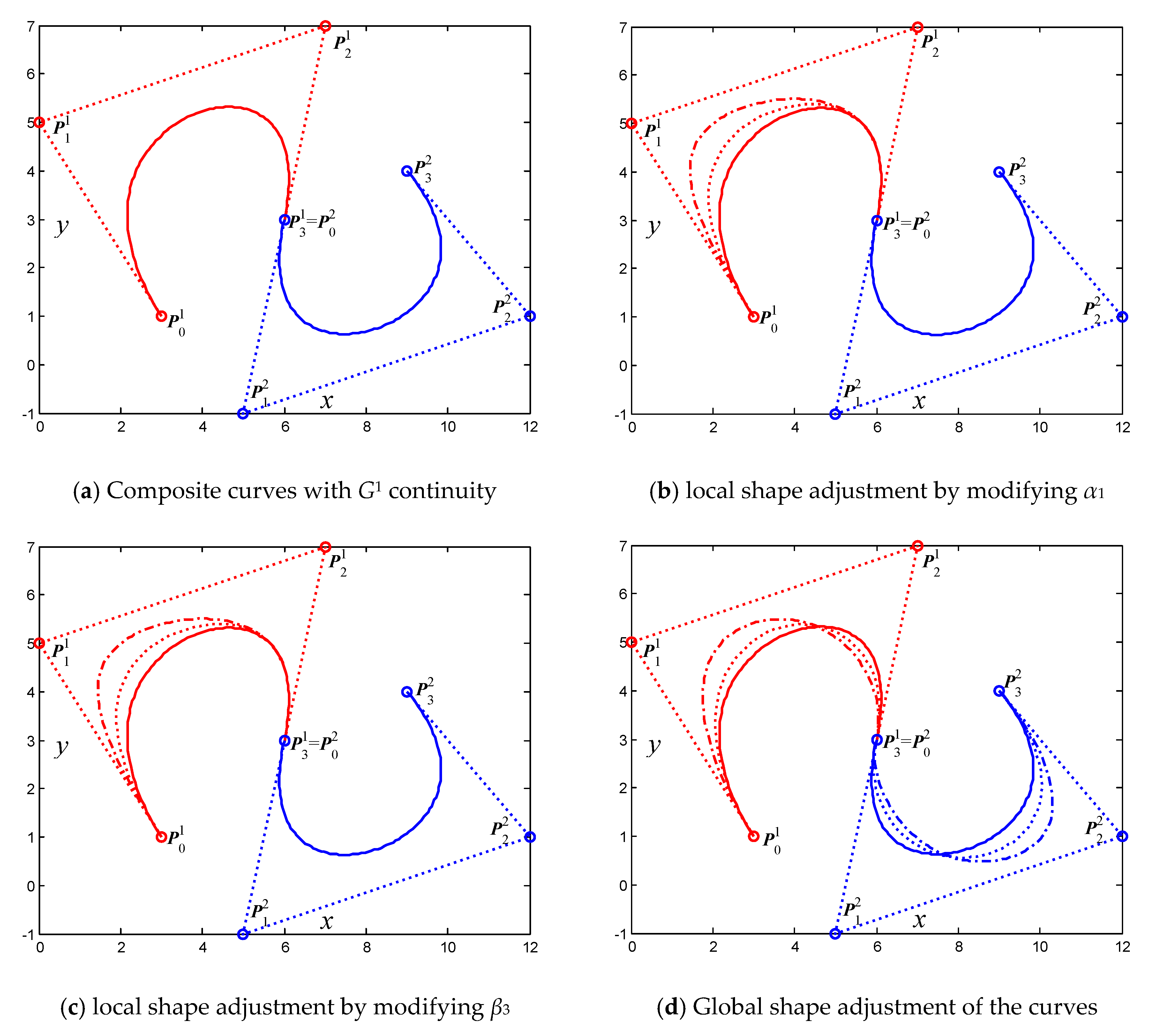
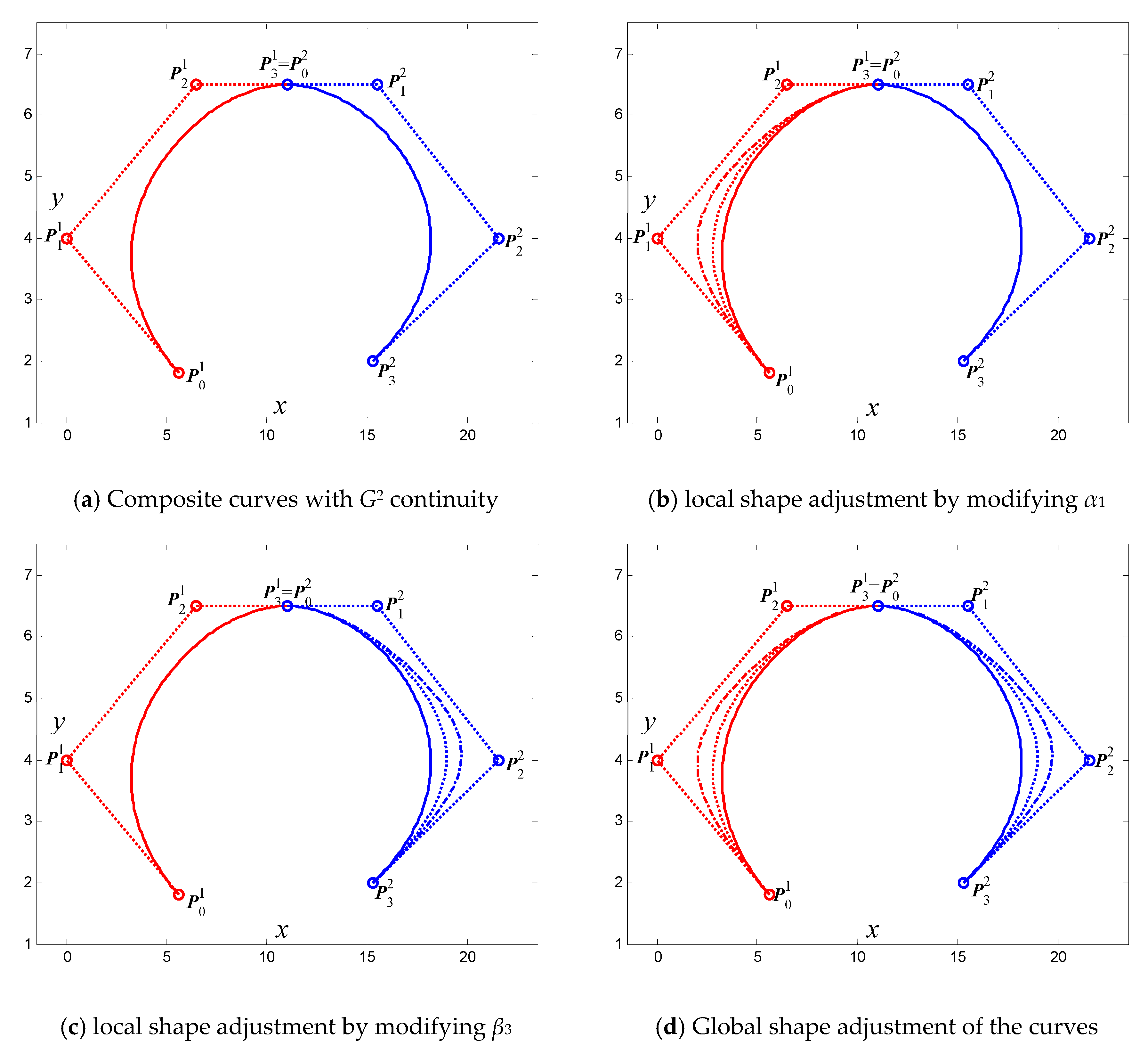
Figure 6 and Figure 7 show examples of shape adjustment of the composite generalized cubic H-Bézier curves with G1 and G2 continuity, respectively, which can be obtained by Algorithm 1. It can be clearly seen from the figure that the generalized cubic H-Bézier curve has superior shape adjustability, which allows broader practical applications of the generalized cubic H-Bézier curve.

3.2. G1 Smooth Continuity for Generalized Cubic H-Bézier Surfaces

For the convenience of this discussion, the splicing of two generalized bicubic H-Bézier surface patches is considered here. Suppose that the two generalized bicubic H-Bézier surface patches to be spliced are defined as follows:
{ S 1 ( u , v ; Ω α , Ω β ) = i = 0 3 j = 0 3 h i , 3 ( u ) h j , 3 ( v ) Q i , j 1 , S 2 ( u , v ; Ω ˜ α , Ω ˜ β ) = i = 0 3 j = 0 3 h i , 3 ( u ) h j , 3 ( v ) Q i , j 2 ,
where Ω α = { α 1 , α 2 , α 3 } , Ω β = { β 1 , β 2 , β 3 } and Ω ˜ α = { α ˜ 1 , α ˜ 2 , α ˜ 3 } , Ω ˜ β = { β ˜ 1 , β ˜ 2 , β ˜ 3 } are the shape control parameters of S 1 ( u , v ; Ω α , Ω β ) and S 2 ( u , v ; Ω ˜ α , Ω ˜ β ) , respectively. Meanwhile, Q i , j k ( i , j = 0 , 1 , 2 , 3 ;   k = 1 , 2 ) represent the control mesh points of the kth surface patch.
Theorem 5.
If the shape parameters and control mesh points of two generalized bicubic H-Bézier surface patches (21) satisfy
{ Q i , 0 2 = Q i , 3 1 ,   ( i = 1 , 2 , 3 ) ,   α ˜ j = α j ,   ( j = 1 , 2 , 3 ) , Q i , 1 2 = γ β 3 ( 1 c o s h β 3 ) ( β ˜ 1 sinh ˜ β 1 ) β ˜ 1 ( β 3 s i n h β 3 ) ( 1 cosh ˜ β 1 ) ( Q i , 3 1 Q i , 2 1 ) + Q i , 3 1 ,   ( i = 0 , 1 , 2 , 3 ) ,
then the u direction of S 1 and the u direction of S 2 reach G1 smooth continuity at the common boundary, where γ > 0 is a real constant.
Proof. 
In order to make two adjacent generalized bicubic H-Bézier surfaces S 1 and S 2 reach G1 smooth continuity in the u direction, they should satisfy G0 continuity first, which means that
S 2 ( u , 0 ; Ω ˜ α , Ω ˜ β ) = S 1 ( u , 1 ; Ω α , Ω β ) .
Based on the boundary properties of the generalized bicubic H-Bézier surface, we can obtain
i = 0 3 h i , 3 ( u ) Q i , 0 2 = i = 0 3 h i , 3 ( u ) Q i , 3 1 .
Due to the linear independence of generalized cubic H-Bézier basis functions, and comparing the coefficients of the two sides of (24), Equation (24) can be further simplified and the following obtained:
{ α ˜ j = α j ,   ( j = 1 , 2 , 3 ) , Q i , 0 2 = Q i , 3 1 ,   ( i = 0 , 1 , 2 , 3 ) .
Also, the two H-Bézier surface patches need to satisfy normal vector direction continuity at the common boundary [26], i.e.,
v S 2 ( u , v ; Ω ˜ α , Ω ˜ β ) | v = 0 × u S 2 ( u , v ; Ω ˜ α , Ω ˜ β ) | v = 0 = γ ( u ) v S 1 ( u , v ; Ω α , Ω β ) | v = 1 × u S 1 ( u , v ; Ω α , Ω β ) | v = 1 ,
where γ ( u ) > 0 is the scaling factor between their normal vectors. In order to facilitate the calculation, (26) can be simplified by the Faux method as follows [26]:
v S 2 ( u , v ; Ω ˜ α , Ω ˜ β ) | v = 0 = γ v S 1 ( u , v ; Ω α , Ω β ) | v = 1 ,
where γ > 0 is a real constant; (27) means that the directions of cross-boundary tangents of the two surfaces are continuous.
After simple calculation, (27) can be simplified to
β ˜ 1 ( 1 cos h β ˜ 1 ) β ˜ 1 sin h β ˜ 1 i = 0 3 h i , 3 ( u ) ( Q i , 1 2 Q i , 0 2 ) = γ β 3 ( 1 cos h β 3 ) β 3 sin h β 3 i = 0 3 h i , 3 ( u ) ( Q i , 3 1 Q i , 2 1 ) .
Due to the linear independence of generalized cubic H-Bézier basis functions, Equation (28) can be simplified by comparing coefficients as follows:
β ˜ 1 ( 1 cos h β ˜ 1 ) β ˜ 1 sin h β ˜ 1 ( Q i , 1 2 Q i , 0 2 ) = γ β 3 ( 1 cos h β 3 ) β 3 sin h β 3 ( Q i , 3 1 Q i , 2 1 ) ,   ( i = 0 , 1 , 2 , 3 ) .
By combining the conclusions in (25), (29) can be reduced to
Q i , 1 2 = γ β 3 ( 1 cos h β 3 ) ( β ˜ 1 sin h β ˜ 1 ) β ˜ 1 ( β 3 sin h β 3 ) ( 1 cos h β ˜ 1 ) ( Q i , 3 1 Q i , 2 1 ) + Q i , 3 1 ,   ( i = 0 , 1 , 2 , 3 ) .
Therefore, (25) and (30) constitute G1 smooth continuity conditions of two generalized bicubic H-Bézier surface patches in the u direction. Theorem 5 is thus proved. □
Theorem 6.
If the shape parameters and control mesh points of two generalized bicubic H-Bézier surface patches (21) satisfy
{ Q 0 , i 2 = Q i , 3 1 ,   ( i = 0 , 1 , 2 , 3 ) ,   β ˜ j = α j ,   ( j = 1 , 2 , 3 ) , Q 1 , i 2 = γ β 3 ( 1 c o s h β 3 ) ( α ˜ 1 sinh ˜ α 1 ) α ˜ 1 ( β 3 s i n h β 3 ) ( 1 cosh ˜ α 1 ) ( Q i , 3 1 Q i , 2 1 ) + Q i , 3 1 ,   ( i = 0 , 1 , 2 , 3 ) .
then the u direction of S 1 and the v direction of S 2 reach G1 smooth continuity at the common boundary, where γ > 0 is a real constant.
Proof. 
In order to make two adjacent generalized bicubic H-Bézier surfaces S 1 and S 2 reach G1 smooth continuity in the u and v directions, they should satisfy G0 continuity first, which means
S 2 ( 0 , v ; Ω ˜ α , Ω ˜ β ) = S 1 ( u , 1 ; Ω α , Ω β ) .
Based on the boundary properties of the generalized bicubic H-Bézier surface, we can obtain
{ β ˜ j = α j ,   ( j = 1 , 2 , 3 ) , Q 0 , i 2 = Q i , 3 1 ,   ( i = 0 , 1 , 2 , 3 ) .
Then, the two H-Bézier surface patches need to satisfy continuity of normal vectors in the u and v directions at the common boundary, i.e., [24,26]
u S 2 ( u , v ; Ω ˜ α , Ω ˜ β ) | u = 0 = γ v S 1 ( u , v ; Ω α , Ω β ) | v = 1 ,
where γ > 0 is a real constant.
After simple calculation, (34) can be simplified to
α ˜ 1 ( 1 cos h α ˜ 1 ) α ˜ 1 sin h α ˜ 1 i = 0 3 h i , 3 ( u ) ( Q 1 , i 2 Q 0 , i 2 ) = γ β 3 ( 1 cos h β 3 ) β 3 sin h β 3 i = 0 3 h i , 3 ( u ) ( Q i , 3 1 Q i , 2 1 ) .
Due to the linear independence of generalized cubic H-Bézier basis functions, (35) can be simplified by comparing coefficients as follows:
α ˜ 1 ( 1 cos h α ˜ 1 ) α ˜ 1 sin h α ˜ 1 ( Q 1 , i 2 Q 0 , i 2 ) = γ β 3 ( 1 cos h β 3 ) β 3 sin h β 3 ( Q i , 3 1 Q i , 2 1 ) .
Furthermore, by combining the conclusions in (33), (36) can be reduced to
Q 1 , i 2 = γ β 3 ( 1 cos h β 3 ) ( α ˜ 1 sin h α ˜ 1 ) α ˜ 1 ( β 3 sin h β 3 ) ( 1 cos h α ˜ 1 ) ( Q i , 3 1 Q i , 2 1 ) + Q i , 3 1 ,   ( i = 0 , 1 , 2 , 3 ) .
Therefore, (33) and (37) constitute the G1 smooth continuity conditions of two generalized bicubic H-Bézier surface patches in the u and v directions. Theorem 6 is thus proved. □
Analogously, for the G1 smooth continuity conditions of two generalized bicubic H-Bézier surface patches in the v direction, it can be easily proved that the following theorem holds.
Theorem 7.
If the shape parameters and control mesh points of two generalized bicubic H-Bézier surface patches (17) satisfy
{ Q 0 , j 2 = Q 3 , j 1 ,   ( j = 0 , 1 , 2 , 3 ) ,   β ˜ j = β j ,   ( j = 1 , 2 , 3 ) , Q 1 , j 2 = γ α 3 ( 1 c o s h α 3 ) ( α ˜ 1 sinh ˜ α 1 ) α ˜ 1 ( α 3 s i n h α 3 ) ( 1 cosh ˜ α 1 ) ( Q 3 , j 1 Q 2 , j 1 ) + Q 3 , j 1 ,   ( j = 0 , 1 , 2 , 3 ) ,
then the v direction of S 1 and the v direction of S 2 reach G1 smooth continuity at the common boundary, where γ > 0 is a real constant.
From the above discussion, it can be seen that in order to obtain a generalized bicubic H-Bézier surface that satisfies the G1 continuity condition, we are only required to calculate the first two rows of control points of the second generalized bicubic H-Bézier surface according to the corresponding conditions; then the last two rows of control points can be given. Here, we devise a specific operable procedure for generating composite generalized bicubic H-Bézier surfaces with G1 smooth continuity in the u direction. The procedure is shown in Algorithm 2.
Algorithm 2. SurfaceJoint(Px, Py, Pz, A1, B1, B2, gama)
 { /* G1 continuity between two generalized bicubic H-Bézier surfaces in the u direction */
 /*   Input:  Px, Py, Pz the control mesh points of the surface S1 */
  /*       A1, B1  the shape parameters of the surface S1  */
  /*       B2    the shape parameters of the surface S2  */
  /*       gama    */
  /*  Output: the composite generalized bicubic H-Bézier surface that satisfies the corresponding continuity condition */
  Surface (Px, Py, Pz, A1, B1);
  Compute the first two rows of control mesh points of S2 according to equation (22) and store them in Qx[i],Qy[i],Qz[i](i = 0,1);
  Give the last two rows of control mesh points Qx[i],Qy[i] (i = 2,3) of S2;
  Surface (Qx, Qy, Qz, A1, B2);
 }
Surface(Px, Py, Pz, A1, B1)
{ /* The generation of generalized bicubic H-Bézier surfaces */
  /* Input: Px, Py, Pz, A1, B1 the control mesh points and shape parameters of the generalized bicubic H-Bézier surfaces */
  /* Output: generalized bicubic H-Bézier surfaces */
  i = 0;
  for (u = 0; u <= 1; u += 0.04)
  {
   Compute the values of basis function for u direction and store them in uh03,uh13,uh23,uh33;
   k = 0;
   for (v = 0; v <= 1; v += 0.04)
   {
    Compute the values of basis function for v direction and store them in vh03,vh13,vh23,vh33, respectively;
    for (j = 0; j < 4; ++ j)
    {
     qvx[j] = vh03*Px[j][0] + vh13*Px[j][1] + vh23*Px[j][2] + vh33*Px[j][3];
     qvy[j] = vh03*Py[j][0] + vh13*Py[j][1] + vh23*Py[j][2] + vh33*Py[j][3];
     qvz[j] = vh03*Pz[j][0] + vh13*Pz[j][1] + vh23*Pz[j][2] + vh33*Pz[j][3];
    }
    qux = uh03 * qvx[0] + uh13 * qvx[1] + uh23 * qvx[2]+ uh33 * qvx[3];
    quy = uh03 * qvy[0] + uh13 * qvy[1] + uh23 * qvy[2] + uh33 * qvy[3];
    quz = uh03 * qvz[0] + uh13 * qvz[1] + uh23 * qvz[2]+ uh33 * qvz[3];
    X(i,k) = qux;
    Y(i,k) = quy;
    Z(i,k) = quz;
    k = k + 1;
   }
   i = i + 1;
  }
  Plot the generalized bicubic H-Bézier surfaces according to X,Y and Z;
}
Remark 5.
According to Algorithm 2, it is easy to obtain composite generalized bicubic H-Bézier surfaces with G1 continuity in the u direction. Similarly, when “the first two rows of control points of the second generalized bicubic H-Bézier surface are calculated according to (22)” in Algorithm 2 is replaced by “the first two rows of control points of the second surface are calculated according to (31)” or “the first two rows of control points of the second surface are calculated in terms of (38)”, respectively, then the above composite surfaces with G1 continuity in the u and v directions or in the v direction can be obtained.
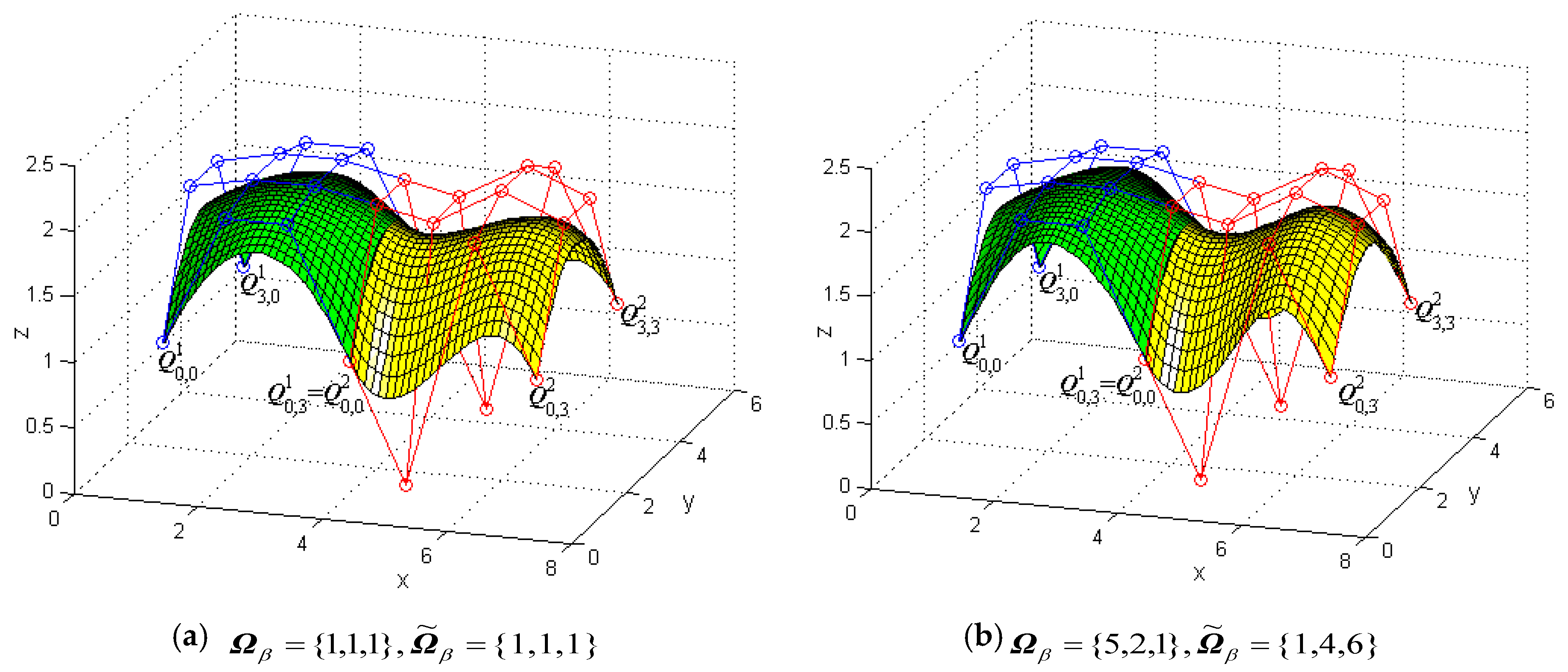
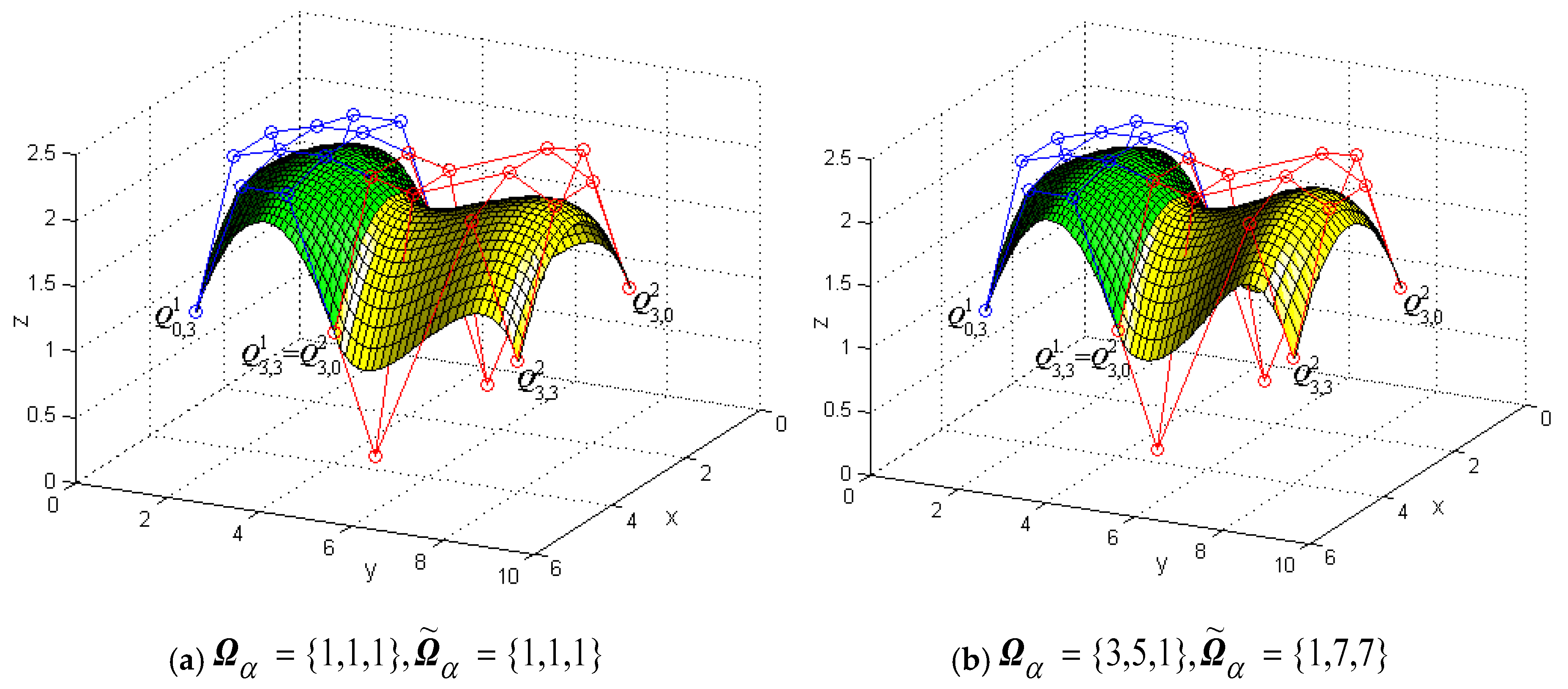
Figure 8 shows a modeling example to illustrate G1 smooth continuity in the u direction between two generalized bicubic H-Bézier surfaces and modifies the shape of the composite surface by changing shape parameters without changing the continuity conditions. In Figure 8, the green mesh surfaces represent the original surface S 1 ( u , v ; Ω α , Ω β ) , the blue polylines are its control mesh, and the circles on the polylines represent control points (for visual effect, only four corners of the surfaces are shown here; the same below). The yellow mesh surfaces are the constructed surfaces S 2 ( u , v ; Ω ˜ α , Ω ˜ β ) which satisfy the G1 smooth continuity conditions in the u direction, that is, Equation (22). The red polylines are the control meshes of the surfaces S 2 ( u , v ; Ω ˜ α , Ω ˜ β ) , and the circles on the polylines denote their control points. In Figure 8a, the shape parameters of surfaces S 1 ( u , v ; Ω α , Ω β ) and S 2 ( u , v ; Ω ˜ α , Ω ˜ β ) are Ω α = Ω ˜ α = { 1 , 2 , 1 } ,   γ = 0.9 . Figure 8b was obtained by modifying the value of the partial shape parameters in Ω β , Ω ˜ β (specific modifications can be seen in Figure 8) on the basis of Figure 8a.
Figure 9 shows a modeling example to demonstrate G1 smooth continuity in the u and v directions between two generalized bicubic H-Bézier surfaces and modifies the shape of the composite surface by changing shape parameters without changing the continuity conditions. In Figure 9, the green mesh surfaces represent the original surface S 1 ( u , v ; Ω α , Ω β ) and the yellow mesh surfaces are the constructed surfaces S 2 ( u , v ; Ω ˜ α , Ω ˜ β ) which satisfy the G1 smooth continuity conditions in the u and v directions, that is, Equation (31). In Figure 9a, the shape parameters of surfaces S 1 ( u , v ; Ω α , Ω β ) and S 2 ( u , v ; Ω ˜ α , Ω ˜ β ) are Ω α = Ω ˜ β = { 1 , 5 , 1 } ,   γ = 0.5 . In Figure 9b, we take Ω α = Ω ˜ β = { 5 , 2 , 5 } and modify some shape parameter values in Ω β , Ω ˜ α (specific modifications can be seen in Figure 9) so as to adjust the shape of the composite surfaces.
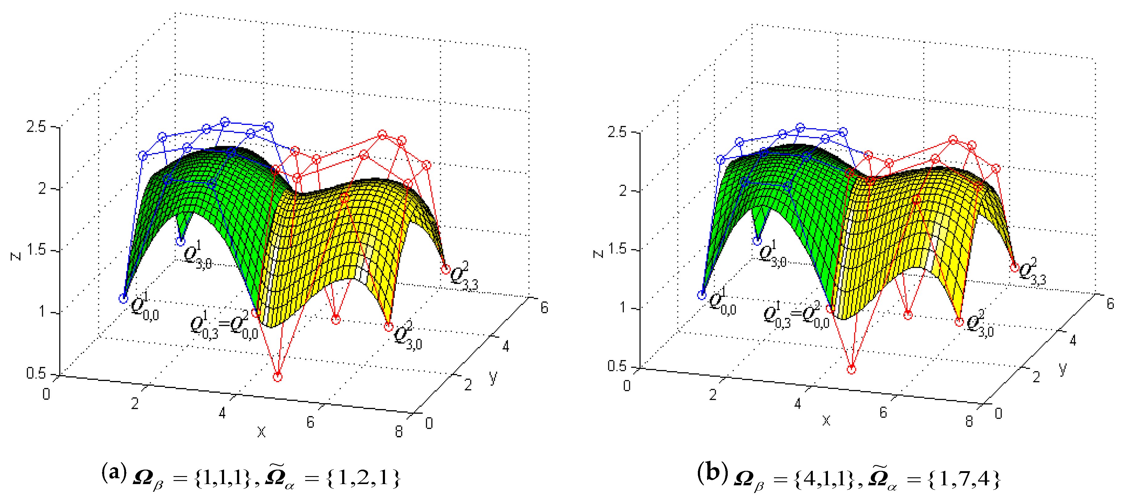
Figure 10 shows a modeling example to display G1 smooth continuity in the v direction between two generalized bicubic H-Bézier surfaces and modifies the shape of the composite surface by changing shape parameters without changing the continuity conditions. In Figure 10, the green mesh surfaces represent the initial surface S 1 ( u , v ; Ω α , Ω β ) and the yellow mesh surfaces are the constructed surfaces S 2 ( u , v ; Ω ˜ α , Ω ˜ β ) which satisfy the G1 smooth continuity conditions in the v direction, that is, Equation (38). In Figure 10a, the shape parameters of surfaces S 1 ( u , v ; Ω α , Ω β ) and S 2 ( u , v ; Ω ˜ α , Ω ˜ β ) are Ω β = Ω ˜ β = { 1 , 2 , 1 } ,   γ = 0.9 . Figure 10b is obtained by modifying the value of the partial shape parameters in Ω α , Ω ˜ α on the basis of Figure 10a. From Figure 8 to Figure 10, it can be seen that when the continuity condition of the surface remains unchanged, modification of the local or global shape of the composite surface can be achieved by modifying the values of multiple shape parameters, which is undoubtedly important in practical applications.

4. Practical Applications

As an extension of the traditional Bézier model, the generalized H-Bézier model can provide a new, alternative tool for the development of computer-aided design and manufacturing (CAD/CAM) application software, which plays a potential role in areas such as the manufacturing industry, computer graphics, etc. By using the approaches proposed in this paper, we can handily construct various kinds of complex curves and surfaces. In this section, we give several representative and convincing examples to illustrate the effectiveness of the proposed methods.
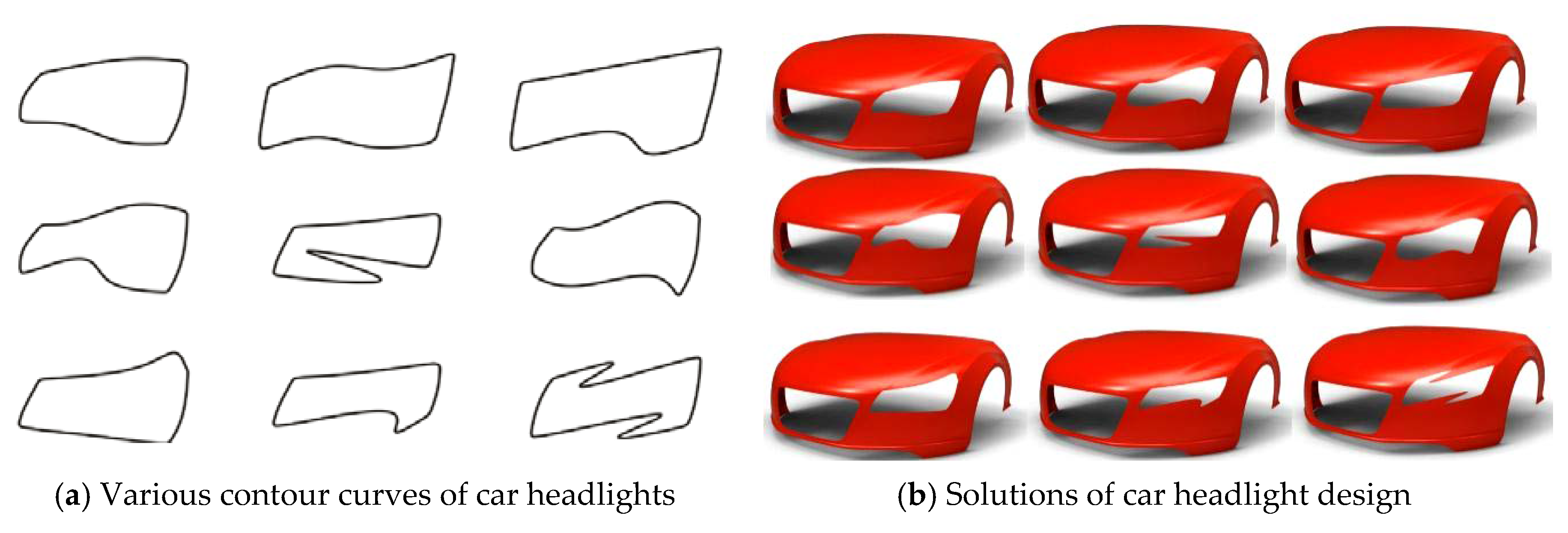
Figure 11 gives an example of designing the contour curves of a car headlight by using generalized H-Bézier curves. In Figure 11, the contour curves of the car headlight are composed of eight generalized H-Bézier curves with G1 smooth continuity. As can be seen from Figure 11, designers can use control points to delineate the initial shape of the contour curves of the car headlight, and then the shape of the initial contour curves can be adjusted slightly by modifying the local shape parameters, so as to quickly obtain satisfactory contour curves in car headlight modeling. In automobile modeling design, the car front face is undoubtedly the most important part of the car body, and the contour curves of the car headlight are an important visual feature in car front face modeling. As shown in Figure 12a, by using the method proposed in this paper, various types of projection contour curve schemes of the car headlight can be obtained quickly. Then we can project the contour curves onto the surface of the car front face, and different styles of car headlight modeling schemes (as shown in Figure 12b) can be obtained using surface trimming technology. The appearance design of a ship hull using generalized H-Bézier surfaces is displayed in Figure 13. In Figure 13, the body of this ship hull is composed of four generalized H-Bézier surfaces with G1 smooth continuity. The modeling examples provided show that our methods are effective and provide an alternative for constructing complex curves and surfaces in industry.

5. Conclusions

In this paper, we investigated some properties of the generalized H-Bézier model and derived the geometric conditions for G1 and G2 smooth continuity between two adjacent generalized H-Bézier curves and for G1 smooth continuity between two adjacent generalized H-Bézier surfaces. Furthermore, we developed two operable procedures of smooth continuity for generalized H-Bézier curves and surfaces, and we utilized several representative and convincing examples to verify the effectiveness of the proposed geometric continuity conditions. Overall, the generalized H-Bézier model provides a useful technology with distinctive characteristics while including the H-Bézier model as a special case. The advantages of the generalized H-Bézier model can be summarized as follows:
(a)
The local controlled generalized H-Bézier model is an extension of the classical H-Bézier model constructed by Pottmann in [9].
(b)
The generalized H-Bézier model inherits all beneficial properties of the classical H-Bézier model, and the composite H-Bézier model has more shape adjustability than the classical H-Bézier one described in [9,10].
(c)
For a composite generalized H-Bézier curve, designers can adjust the global and local shape of the curve by changing the shape parameters without having to redetermine the control points.
We will focus on studying the interpolation and approximation of the generalized H-Bézier model in future work. In addition, some interesting directions for future research would be to realize curve editing, user control, and shape optimization for the generalized H-Bézier model by finding optimal shape parameters.

Author Contributions

Conceptualization, G.H. and M.A.; methodology, F.L. and K.T.M.; software, F.L. and G.H.; validation, F.L., G.H. and M.A.; formal analysis, G.H. and K.T.M.; investigation, F.L., G.H. and M.A.; resources, G.H. and K.T.M.; data curation, F.L. and M.A.; writing—original draft preparation, F.L. and G.H.; writing—review and editing, M.A. and K.T.M.; visualization, F.L.; supervision, G.H. and K.T.M.; project administration, F.L., M.A. and K.T.M.; funding acquisition, M.A. and K.T.M. All authors have read and agreed to the published version of the manuscript.

Funding

This research was funded by JST CREST Grant No. JPMJCR1911, JSPS Grant-in-Aid for Scientific Research (B) Grant No. 19H02048, and JSPS Grant-in-Aid for Challenging Exploratory Research Grant No. 26630038.

Acknowledgments

We are very grateful to anonymous reviewers for their thoughtful and meaningful comments that help us to improve the manuscript.

Conflicts of Interest

The authors declare no conflict of interest.

References

  1. Piegl, L.; Tiller, W. The NURBS Book, 2nd ed.; Springer: New York, NY, USA, 1997; pp. 340–348. [Google Scholar]
  2. Li, J.G.; Zhu, C.G. Curve and surface construction based on the generalized toric-Bernstein basis functions. Open Math. 2020, 18, 36–56. [Google Scholar] [CrossRef] [Green Version]
  3. Hu, G.; Wu, J.L. Generalized quartic H-Bézier curves: Construction and application to developable surfaces. Adv. Eng. Soft. 2019, 138, 102723. [Google Scholar] [CrossRef]
  4. Hu, G.; Cao, H.X.; Zhang, S.X.; Wei, G. Developable Bézier-like surfaces with multiple shape parameters and its continuity conditions. Appl. Math. Model. 2017, 45, 728–747. [Google Scholar] [CrossRef]
  5. Hu, G.; Zhang, G.; Wu, J.L.; Qin, X.Q. A novel extension of the Bézier model and its applications to surface modeling. Adv. Eng. Soft. 2018, 125, 27–54. [Google Scholar] [CrossRef]
  6. Meek, D.S.; Walton, D.J. Geometric Hermite interpolation with Tschirnhausen cubics. J. Comput. Appl. Math. 1997, 81, 299–309. [Google Scholar] [CrossRef] [Green Version]
  7. Pelosi, F.; Farouki, R.T.; Manni, C.; Sestini, A. Geometric Hermite interpolation by spatial Pythagorean-hodograph cubics. Adv. Comput. Math. 2005, 22, 325–352. [Google Scholar] [CrossRef]
  8. Ait-Haddou, R.; Bartoň, M. Constrained multi-degree reduction with respect to Jacobi norms. Comput. Aided Geom. Des. 2016, 42, 23–30. [Google Scholar] [CrossRef] [Green Version]
  9. Pottmann, H. The geometry of Tchebycheffian spines. Comput. Aided Geom. Des. 1993, 10, 181–210. [Google Scholar] [CrossRef]
  10. Li, Y.J.; Wang, G.Z. Two kinds of B-basis of the algebraic hyperbolic space. J. Zhejiang Univ. Sci. A 2005, 6, 750–759. [Google Scholar]
  11. Wang, G.Z.; Yang, Q.M. Planar cubic hybrid hyperbolic polynomial curve and its shape classification. Prog. Nat. Sci. 2004, 14, 41–46. [Google Scholar] [CrossRef]
  12. Qian, J.; Tang, Y. The application of H-Bézier-like curves in engineering. J. Numer. Methods Comput. Appl. 2007, 28, 167–178. [Google Scholar]
  13. Fan, F.T.; Wang, G.Z. Conversion matrix between two bases of the algebraic hyperbolic space. J. Zhejiang Univ. Sci. A 2006, 7, 181–186. [Google Scholar] [CrossRef]
  14. Wu, R. Shape analysis of planar cubic H-Bézier curve. Acta Math. Appl. Sin. 2007, 30, 816–821. [Google Scholar]
  15. Zhao, H.Y.; Wang, G.J. Shape control of cubic H-Bézier curve by moving control point. J. Inform. Comput. Sci. 2007, 4, 871–878. [Google Scholar]
  16. Wang, Y.; Tan, J.; Li, Z. Multidegree reduction approximation of H-Bézier curves. J. Comput. Aided Des. Comput. Graph. 2011, 23, 1838–1842. [Google Scholar]
  17. Qin, X.Q.; Hu, G.; Yang, Y.; Wei, G. Construction of PH splines based on H-Bézier curves. Appl. Math. Comput. 2014, 238, 460–467. [Google Scholar] [CrossRef]
  18. Lee, R.; Ahn, Y.J. Limit curve of H-Bézier curves and rational Bézier curves in standard form with the same weight. J. Comput. Appl. Math. 2015, 281, 1–9. [Google Scholar] [CrossRef]
  19. Cao, H.; Hu, G.; Wei, G.; Zhang, S. Offset approximation of hybrid hyperbolic polynomial curves. Results Math. 2017, 72, 1055–1071. [Google Scholar] [CrossRef]
  20. Huang, Y.; Wang, G.Z. An orthogonal basis for the hyperbolic hybrid polynomial space. Sci. China Ser. Inform. Sci. 2007, 50, 21–28. [Google Scholar] [CrossRef]
  21. Zhang, J.W.; Krause, F.L.; Zhang, H.Y. Unifying C-curves and H-curves by extending the calculation to complex numbers. Comput. Aided Geom. Des. 2005, 22, 865–883. [Google Scholar] [CrossRef]
  22. Hu, G.; Wu, J.L.; Qin, X.Q. A new approach in designing of local controlled developable H-Bézier surfaces. Adv. Eng. Soft. 2018, 121, 26–38. [Google Scholar] [CrossRef]
  23. Wang, G.J.; Wang, G.Z.; Zheng, J.M. Computer Aided Geometric Design; Springer–Higher Education Press: Beijing, China, 2001. [Google Scholar]
  24. Hu, G.; Bo, C.; Qin, X. Continuity conditions for tensor product Q-Bézier surfaces of degree (m, n). Comp. Appl. Math. 2018, 37, 4237–4258. [Google Scholar] [CrossRef]
  25. Hu, G.; Bo, C.; Wu, J.; Wei, G.; Hou, F. Modeling of free-form complex curves using SG-Bézier curves with constraints of geometric continuities. Symmetry 2018, 10, 545. [Google Scholar] [CrossRef] [Green Version]
  26. Hu, G.; Bo, C.C.; Wei, G.; Qin, X.Q. Shape-adjustable generalized Bézier Surfaces: Construction and its geometric continuity conditions. Appl. Math Comput. 2020, 378, 125215. [Google Scholar]
Figure 1. Generalized cubic H-Bézier basis functions.
Mathematics 08 00924 g001
Figure 2. The translational speed functions with different parameters t.
Mathematics 08 00924 g002aMathematics 08 00924 g002b
Figure 3. The influences of shape parameters on generalized cubic H-Bézier curves.
Mathematics 08 00924 g003aMathematics 08 00924 g003b
Figure 4. The effects of α 1 on the generalized bicubic H-Bézier surface.
Mathematics 08 00924 g004
Figure 5. The effects of β 3 on the generalized bicubic H-Bézier surface.
Mathematics 08 00924 g005aMathematics 08 00924 g005b
Figure 6. Shape adjustment of the generalized cubic H-Bézier curves with G1 continuity.
Mathematics 08 00924 g006
Figure 7. Shape adjustment of the generalized cubic H-Bézier curves with G2 continuity.
Mathematics 08 00924 g007
Figure 8. Generalized bicubic H-Bézier surfaces with G1 continuity in the u direction.
Mathematics 08 00924 g008
Figure 9. Generalized bicubic H-Bézier surfaces with G1 continuity in the u and v directions.
Mathematics 08 00924 g009
Figure 10. Generalized bicubic H-Bézier surfaces with G1 continuity in the v direction.
Mathematics 08 00924 g010
Figure 11. Eight generalized H-Bézier curves used to define the contour curves of a car headlight.
Mathematics 08 00924 g011
Figure 12. Designing a car headlight using projection and pruning techniques.
Mathematics 08 00924 g012
Figure 13. Designing the surface model of a ship hull.
Mathematics 08 00924 g013