Kinetics Study in Parachute Landing Fall Technique by Comparing Professional and Amateur Malaysian Army Parachutists Using Kane’s Method


Abstract
1. Introduction
2. Materials and Methods
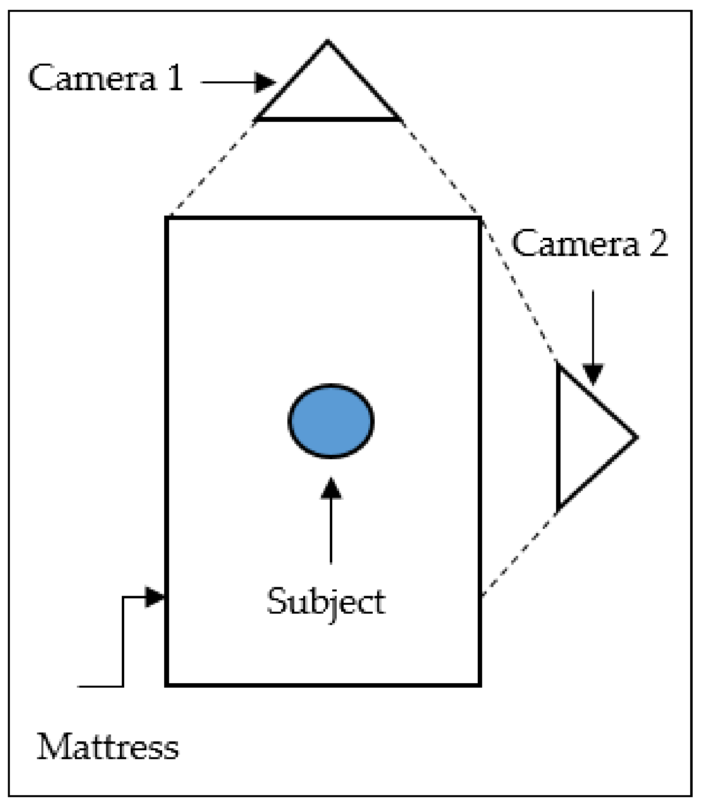
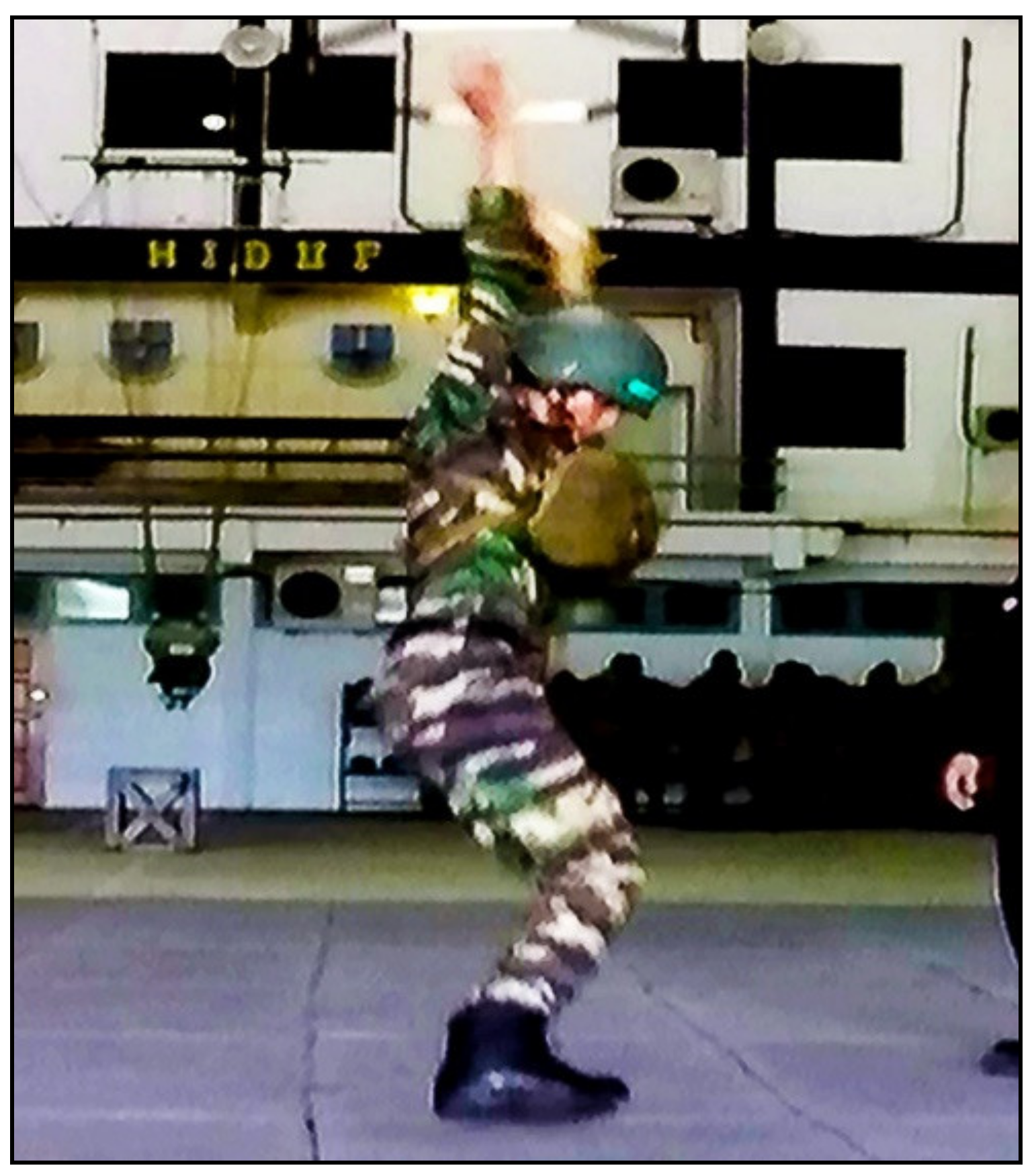
2.1. Experimental
2.2. Data Analysis
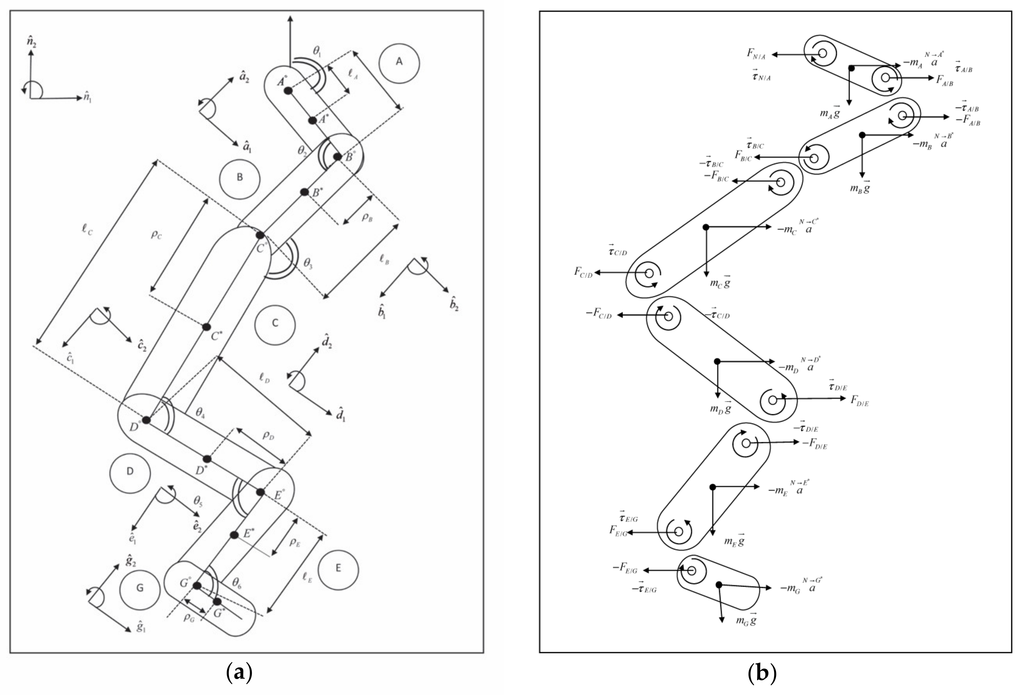
2.3. Mathematical Modelling (Sagittal Plane)
- = centre of mass segments A, B, C, D, E and G, respectively
- = length of segments
- = distances of centre of mass from their proximal ends
- = mutually orthogonal unit
- = torque of each joints
| : | Vector of applied torque |
| M: | Mass matrix |
| : | Angular acceleration vector |
| : | Vector of moments from gravitational forces |
| : | Vector of moments from external forces |
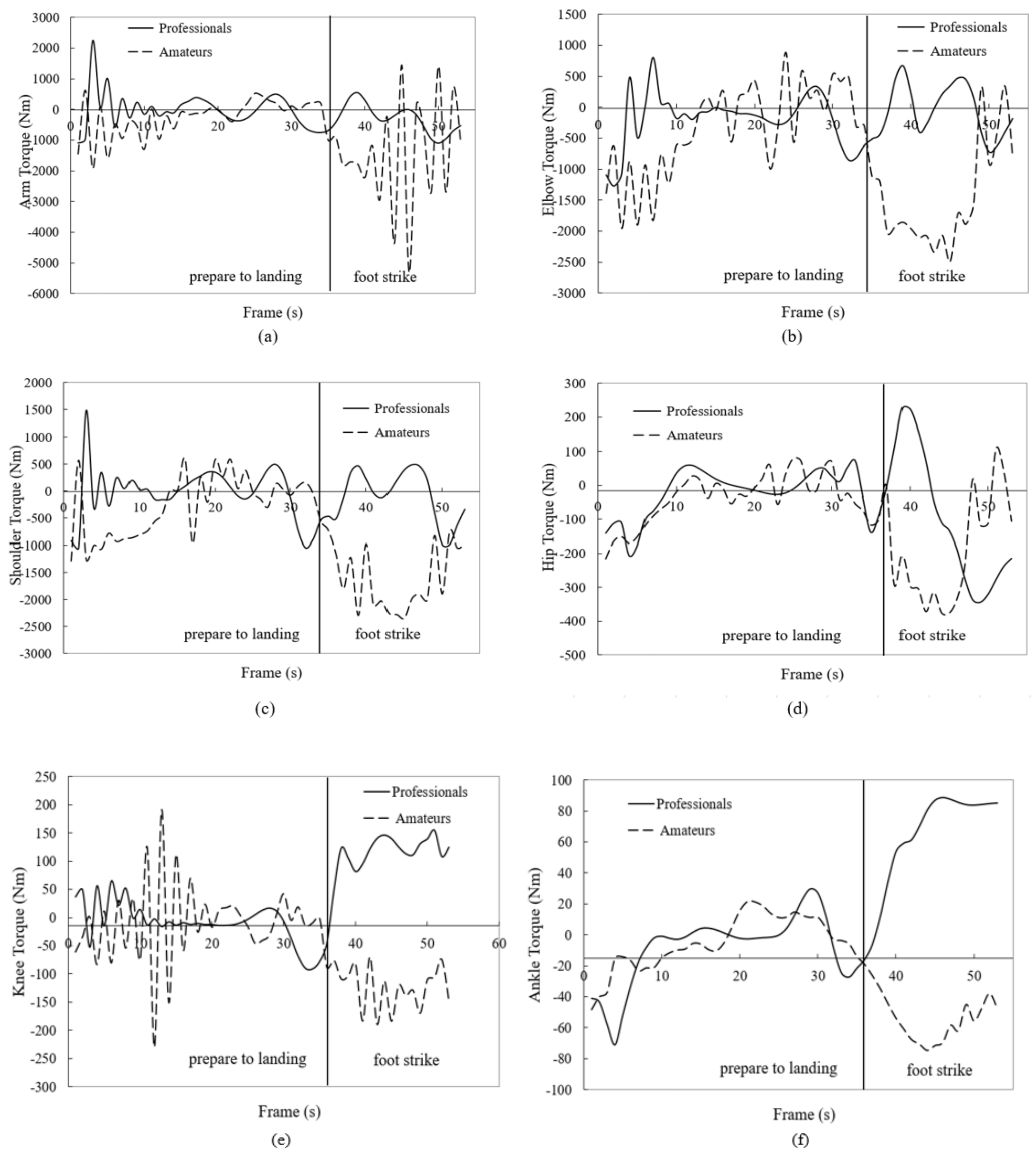
3. Results
4. Discussion
5. Conclusions
Author Contributions
Funding
Acknowledgments
Conflicts of Interest
References
- Chervak, M.C.; Hooper, T.; Brennan, F.H.; Craigh, S.C.; Girasek, D.C.; Schaefer, R.A.; Barbour, G.; Ywe, K.S.; Jones, B.H. A systematic process to prioritise prevention activities sustaining progress toward the reduction of military injuries. Am. J. Prev. Med. 2010, 38, 11–18. [Google Scholar] [CrossRef] [PubMed]
- Niu, W.; Fan, Y. Terrain stiffness and ankle biomechanics during simulated half-squat parachute landing. Aviat. Space Environ. Med. 2013, 84, 1262–1267. [Google Scholar] [CrossRef] [PubMed]
- Whitting, J.; Steele, J.R.; Jaffrey, M.A.; Munro, B. Parachute landing fall characteristics at three realistic vertical descent velocities. Aviat. Space Environ. Med. 2007, 78, 1135–1142. [Google Scholar] [CrossRef] [PubMed]
- Niu, W.; Wang, Y.; He, Y.; Fan, Y.; Zhao, Q. Biomechanical gender differences of the ankle joint during simulated half-squat parachute landing. Aviat. Space Environ Med. 2010, 81, 761–767. [Google Scholar] [CrossRef]
- Taylor, K.A.; Terry, M.E.; Uttukar, G.M.; Spritzer, C.E.; Queen, R.M.; Irribarra, L.A.; Garrett, W.E.; DeFrate, L.E. Measurement of in vivo anterior cruciate ligament strain during dynamic jump landing. J. Biomech. 2011, 44, 365–371. [Google Scholar] [CrossRef]
- Malinzak, R.A.; Colby, S.M.; Kirkendall, D.T.; Yu, B.; Garrett, W.E. Comparison of knee joint motion patterns between men and women in selected athletic tasks. Clin. Biomech. 2011, 16, 438–445. [Google Scholar] [CrossRef]
- Colby, S.; Francisco, A.; Yu, B.; Kirkendall, D.; Finch, M.J.; Garret, W. Electromyographic and kinematic analysis of cutting maneuvers implications for anterior cruciate ligament injury. Am. J. Sport Med. 2000, 28, 234–240. [Google Scholar] [CrossRef]
- Patel, S.A.; Hageman, J.; Quatman, C.E.; Wordeman, S.C.; Hewett, T.E. Prevalence and Location of Bone Bruises Associated with Anterior Cruciate Ligament Injury and Implications for Mechanism of Injury: A Systematic Review. Sports Med. 2014, 44, 281–293. [Google Scholar] [CrossRef]
- Neves, E.; Souza, M.; Almeida, R. Military parachuting injuries in Brazil. Injury 2009, 40, 897–900. [Google Scholar] [CrossRef]
- Ellitsgaard, N. Parachuting injuries: A study of 110,000 sports jumps. Injury 1987, 21, 13–17. [Google Scholar] [CrossRef]
- Ball, V.L.; Sutton, J.A.; Aicha Hull, A.; Sinnott, B.A. Traumatic injury patterns associated with static line parachuting. Wilderness Environ. Med. 2014, 25, 89–93. [Google Scholar] [CrossRef] [PubMed]
- Knapik, J.J.; Spiess, A.; Swedler, D.I.; Grier, T.L.; Darakjy, S.; Jones, B. Systematic review of the parachute ankle brace injury risk reduction and cost effectiveness. Am. J. Prev. Med. 2010, 38, 182–188. [Google Scholar] [CrossRef] [PubMed]
- Wu, D.; Zheng, C.; Wu, J.; Wang, L.; Wei, X.; Wang, L. Protective knee braces and the biomechanics of the half-squat parachute landing. Aerosp. Med. Hum. Perform. 2018, 89, 26–31. [Google Scholar] [CrossRef] [PubMed]
- Aziz, S.; Rambely, A.S.; Rauf, U.F.A. Kinematics study on PLF technique by comparing professional and amateur Malaysian army parachutists based on event during landing. J. Phys. Conf. Ser. 2019, 1366, 012054. [Google Scholar] [CrossRef]
- Abidin, S.B.Z.; Jusoh, W.N.I.W.; Beng, G.K. Kinematic analysis on reaching activity for hemiparetic stroke subjects using simplified video processing method. Malays. J. Fundam. Appl. Sci. 2018, 14, 386–390. [Google Scholar] [CrossRef][Green Version]
- Ariffin, M.S.; Rambely, A.S. Optimization of upper extremity muscles using compound bow via lagrange multiplier method. AIP Conf. Proc. 2016, 1750, 030030. [Google Scholar]
- Ponvel, P.; Singh, D.K.A.; Beng, G.K.; Chai, S.C. Factors affecting upper extremity kinematics in healthy adults: A systematic review. Crit. Rev. Phys. Rehabil. Med. 2019, 31, 101–123. [Google Scholar] [CrossRef]
- Ramlee, M.H.; Gan, K.B. Function and biomechanics of upper limb in post-stroke patients—A systematic review. J. Mech. Med. Biol. 2017, 17, 1750099. [Google Scholar] [CrossRef]
- Kernozek, T.W.; Torry, M.R.; Van Hoof, H.; Cowley, H.; Tanner, S. Gender differences in frontal and sagittal plane biomechanics during drop landing. J. Am. Coll. Sports Med. 2005, 37, 1003–1012. [Google Scholar] [CrossRef]
- Huston, L.; Vibert, B.; Ashton-Miller, J.; Wojtys, E. Gender differences in knee angle when landing from a drop-jump. Am. J. Knee Surg. 2001, 14, 215–220. [Google Scholar]
- Chappell, J.; Limpisvasti, O. Effect of neuromuscular training program on the kinetics and kinematics of jumping tasks. Am. J. Sports Med. 2008, 36, 1081–1086. [Google Scholar]
- Chappell, J.; Herman, D.; Knight, B.; Kirkendall, D.; Garrett, W.; Yu, B. Effect of fatigue on knee kinetics and kinematics in stop-jump task. Am. Orthop. Soc. Sports Med. 2005, 33, 1022–1029. [Google Scholar] [CrossRef] [PubMed]
- Decker, M.J.; Torry, M.R.; Wyland, D.J.; Sterett, W.I.; Steadman, J.R. Gender differences in lower extremity kinematics, kinetics and energy absorption during landing. Clin. Biomech. 2003, 18, 662–669. [Google Scholar] [CrossRef]
- Protopapadaki, A.; Drechsler, W.I.; Cramp, M.C.; Coutts, F.J.; Scott, O.M. Hip, knee, ankle kinematics and kinetics during stair ascent and descent in healthy young individuals. Clin. Biomech. 2007, 22, 203–210. [Google Scholar] [CrossRef]
- Huston, R.L. Multibody Dynamics; Butterworth-Heinemann: Boston, MA, USA, 1990. [Google Scholar]
- Purushotham, A.; Anjeneyulu, J. Kane’s Method for Robotic Arm Dynamics: A Novel Approach. J. Mech. Civ. Eng. 2013, 6, 7–13. [Google Scholar] [CrossRef]
- Wan Din, W.R.; Rambely, A.S. Biomechanics of rifle shooting model: Effects of rifle dynamics in target accuracy. In Proceedings of the 2nd International Conference on Mathematical Sciences, Kuala Lumpur, Malaysia, 30 November–3 December 2010; pp. 136–141. [Google Scholar]
- Ariff, F.H.M.; Rambely, A.S.; Ghani, N.A.A. Shoulder’s modeling via Kane’s method: Determination of torques in smash activity. IFMBE Proc. 2011, 35, 207–209. [Google Scholar] [CrossRef]
- Tumit, N.P.; Rambely, A.S.; Shamsul, B.M.T.; Shahriman, A.B.; Ng, Y.G.; Deros, B.M.; Zailina, H.Y.; Goh, M.; Manohar, A.; Ismail, I.A.; et al. An Upper Limb Mathematical Model of an Oil Palm Harvester. AIP Conf. Prof. 2014, 1614, 973–979. [Google Scholar] [CrossRef]
- Ismail, K.N.S.K.; Basah, S.N.; Omar, N.H.; Murugappan, M.; Yaacob, S.B. Matematical modeling of human Body for lifting task. In Proceedings of the IEEE International Conference on Control System, Computing and Engineering, Penang, Malaysia, 23–25 November 2012. [Google Scholar]
- Sharifah, A.A.R.; Azmin, S.R.; Rokiah, R.A. A biomechanical model via Kane’s equation-solving trunk motion with load carriage. Am. J. Sci. Ind. Res. 2011, 2, 678–685. [Google Scholar] [CrossRef]
- Page, A.; Ayala, G.; Leon, M.T.; Peydro, M.F.; Prat, J.M. Normalizing temporal pattern to analyse sit-to-stand movement by using registration of functional data. J. Biomech. 2006, 39, 2526–2534. [Google Scholar] [CrossRef]
- Zin, M.A.M.; Rambely, A.S.; Ariff, N.M.; Ariffin, M.S. Smoothing and differentiation of kinematics data using functional data analysis approach: An application of automatic and subjective method. Appl. Sci. 2020, 10, 2493. [Google Scholar] [CrossRef]
- Din, W.R.W.; Rambely, A.S.; Jemain, A.A. Load carriage analysis for military using functional data analysis technique: Registration and permutation test. Int. J. Basic Appl. Sci. 2015, 4, 1–9. [Google Scholar] [CrossRef][Green Version]
- Boden, B.P.; Torg, J.S.; Knowles, S.B.; Hewett, T.E. Video analysis of anterior cruciate ligament injury: Abnormalities in hip and ankle kinematics. Am. J. Sport Med. 2009, 37, 252–259. [Google Scholar] [CrossRef]
- Sell, T.; Chu, Y.; Abt, J.P.; Nagai, T.; Deluzio, J.; McGrail, M.; Rowe, R.; Lephart, S. Minimal addition weight of combat equipment alters air assault soldiers landing biomechanics. Mil. Med. 2010, 17, 41–47. [Google Scholar] [CrossRef] [PubMed]
- Shimokochi, Y.; Yong Lee, S.; Shultz, S.J.; Schmitz, R.J. The relationships among sagittal-plane lower extremity moments: Implications for landing strategy in anterior cruciate ligament injury prevention. J. Athl. Train. 2009, 44, 33–38. [Google Scholar] [CrossRef] [PubMed]


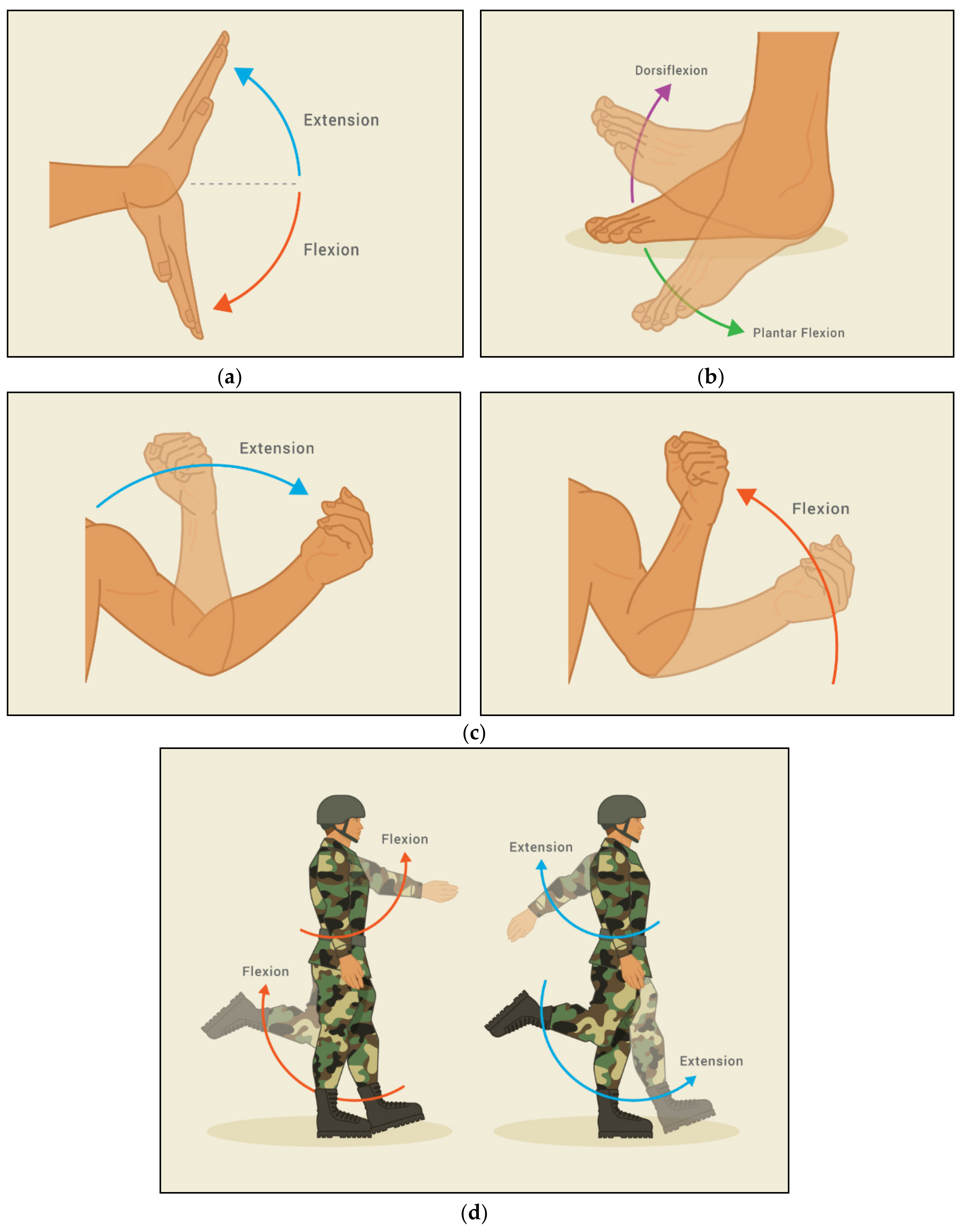
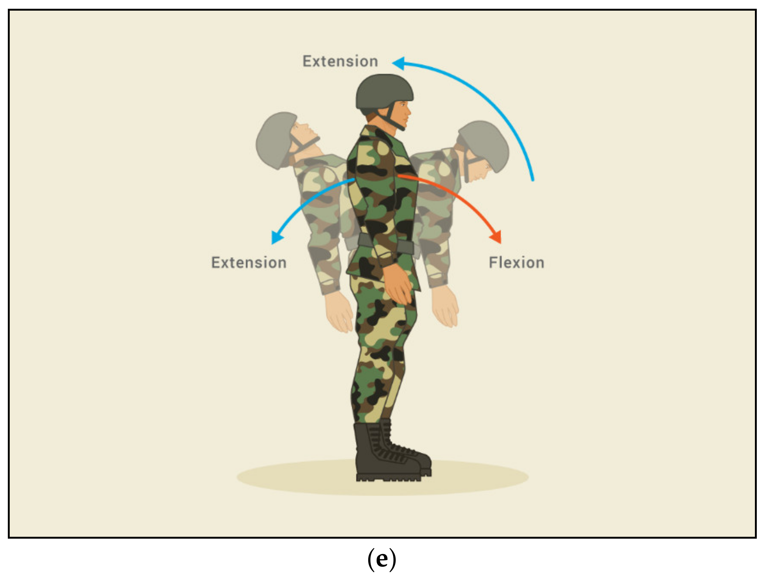
| Joint | Phase | Joint Movement Direction |
|---|---|---|
| Arm | Preparation to land | Extension (−) |
| Foot strike | Extension (−) | |
| Elbow | Preparation to land | Flexion (+) |
| Foot strike | Flexion (+) | |
| Shoulder | Preparation to land | Flexion (+) |
| Foot strike | Flexion (+) | |
| Hip | Preparation to land | Flexion (+) |
| Foot strike | Flexion (+) | |
| Knee | Preparation to land | Flexion (+) |
| Foot strike | Flexion (+) | |
| Ankle | Preparation to land | Plantar Flexion (−) |
| Foot strike | Dorsiflexion (+) |
| Professional | Amateurs | |||||
|---|---|---|---|---|---|---|
| Variable | Mean ± SD | Max | Min | Mean ± SD | Max | Min |
| Torque (Nm) | ||||||
| Wrist | −384.73 ± 26.95 | −751.32 | −1590.02 | 212.05 ± 78.67 | 2809.92 | −4627.90 |
| Elbow | 158.76 ± 38.86 | 656.97 | −134.27 | 494.07 ± 94.61 | 3318.81 | −3185.36 |
| Shoulder | 177.78 ± 48.47 | 300.03 | 153.52 | 160.42 ± 66.56 | 3074.12 | −4236.73 |
| Hip | 50.44 ± 19.82 | 65.23 | 51.35 | −22.62 ± 19.75 | 710.43 | −968.52 |
| Knee | 49.34 ± 18.73 | 93.99 | 61.08 | 42.00 ± 23.23 | 123.57 | −187.37 |
| Ankle | −24.30 ± −3.15 | −26.75 | −51.42 | 11.43 ± −8.37 | 87.62 | −57.96 |
| Frame | Runge-Kutta (Rad) (r) | Experimental Result (Rad)(s) | |
|---|---|---|---|
| 1 | 1.90437 | 1.89949 | 0.25691% |
| 2 | 1.98698 | 1.99188 | 0.24596% |
| 3 | 1.74827 | 1.75034 | 0.11842% |
| 4 | 1.79565 | 1.79817 | 0.14016% |
| 5 | 2.07085 | 2.06973 | 0.05394% |
© 2020 by the authors. Licensee MDPI, Basel, Switzerland. This article is an open access article distributed under the terms and conditions of the Creative Commons Attribution (CC BY) license (http://creativecommons.org/licenses/by/4.0/).
Share and Cite
Aziz, S.; Rambely, A.S.; Gan, K.B.; Wan Din, W.R. Kinetics Study in Parachute Landing Fall Technique by Comparing Professional and Amateur Malaysian Army Parachutists Using Kane’s Method. Mathematics 2020, 8, 917. https://doi.org/10.3390/math8060917
Aziz S, Rambely AS, Gan KB, Wan Din WR. Kinetics Study in Parachute Landing Fall Technique by Comparing Professional and Amateur Malaysian Army Parachutists Using Kane’s Method. Mathematics. 2020; 8(6):917. https://doi.org/10.3390/math8060917
Chicago/Turabian StyleAziz, Syazwana, Azmin Sham Rambely, Kok Beng Gan, and Wan Rozita Wan Din. 2020. "Kinetics Study in Parachute Landing Fall Technique by Comparing Professional and Amateur Malaysian Army Parachutists Using Kane’s Method" Mathematics 8, no. 6: 917. https://doi.org/10.3390/math8060917
APA StyleAziz, S., Rambely, A. S., Gan, K. B., & Wan Din, W. R. (2020). Kinetics Study in Parachute Landing Fall Technique by Comparing Professional and Amateur Malaysian Army Parachutists Using Kane’s Method. Mathematics, 8(6), 917. https://doi.org/10.3390/math8060917