Interacting Ru(bpy)
3
2
+
Dye Molecules and TiO2 Semiconductor in Dye-Sensitized Solar Cells

 ,
,  and
and
Abstract
1. Introduction
2. Model formulation and Assumptions
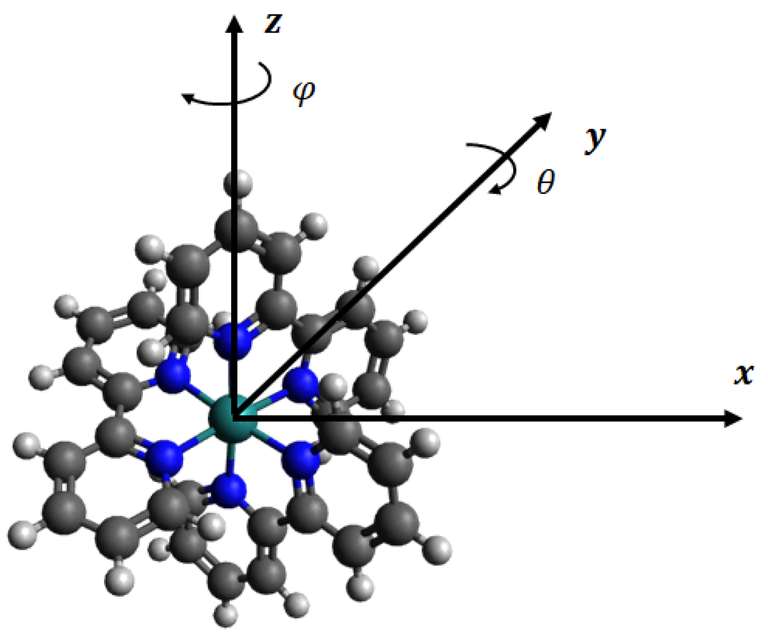
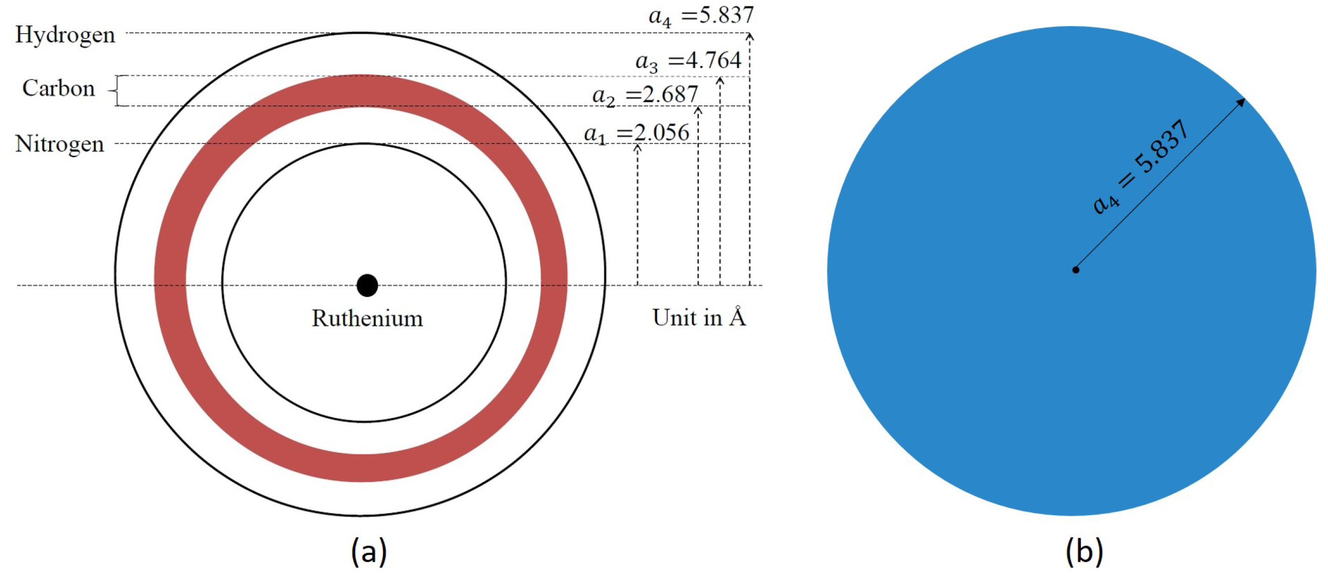
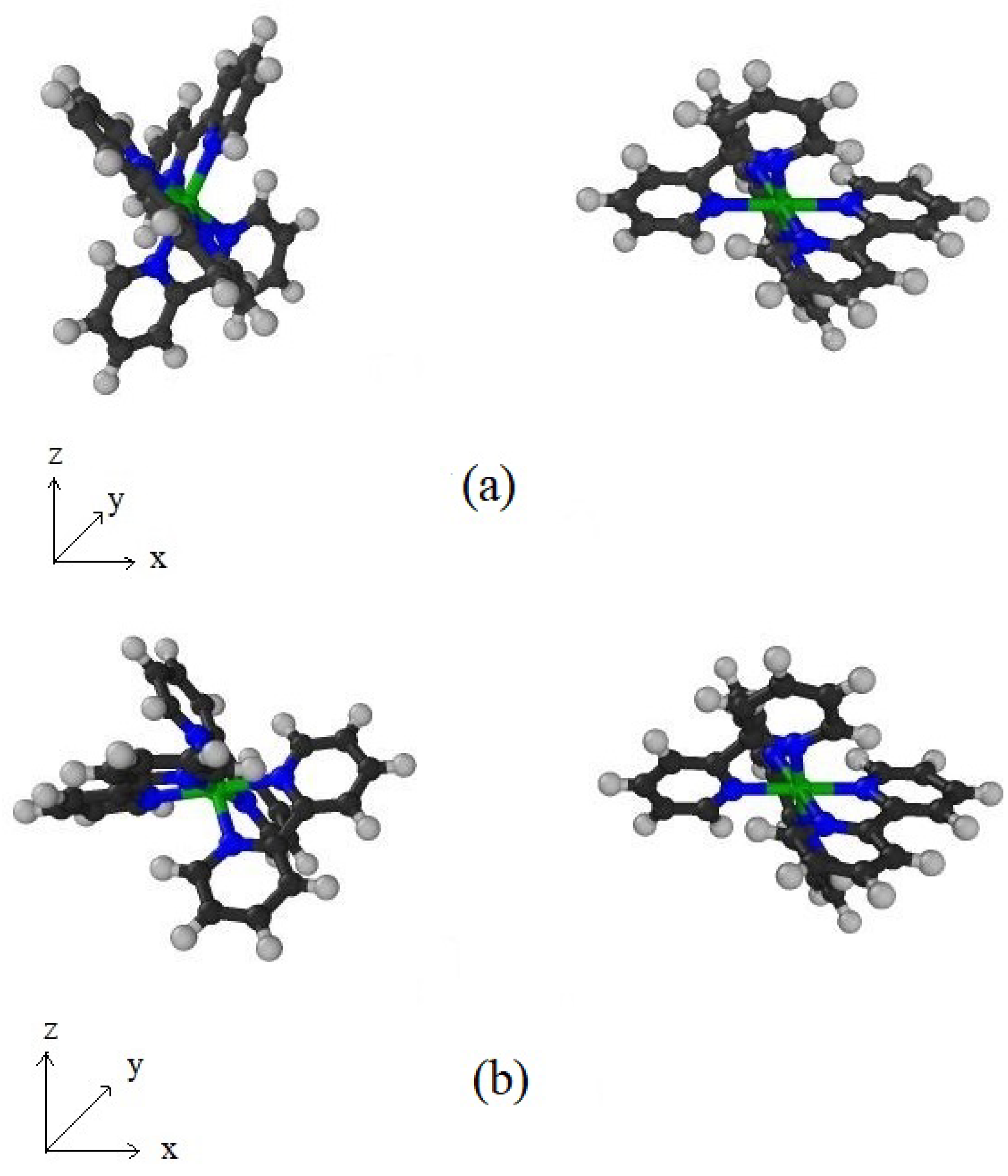
2.1. Structure of Ru(bpy)
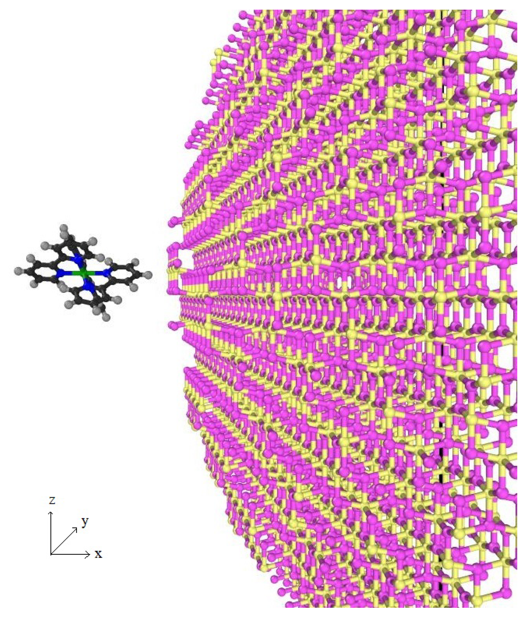
2.2. Structure of TiO
2.3. Potential Function and Continuum Approach
- (i)
- Single atom interacting with a spherical surface:Following the work of Cox et al. [27], the two integrals and can be expressed aswhere , a is a radius of the sphere, and Z denotes the distance between the atom and the centre of the spherical surface.
- (ii)
- Single atom interacting with a solid sphere:Analytical expressions for this interaction were derived by Baowan and Thamwattana [32], and are restated here aswhere again .
- (iii)
- Interaction between two spherical surfaces:
- (iv)
- Spherical surface interacting with a spherical shell (with finite thickness ):
- (v)
- Spherical surface interacting with a solid sphere:
3. Interaction Energies between Dye and Semiconductor
3.1. Ru(bpy)–Ru(bpy)
3.1.1. Model I
3.1.2. Model II
3.2. Ru(bpy)–TiO
3.2.1. Model I
3.2.2. Model II
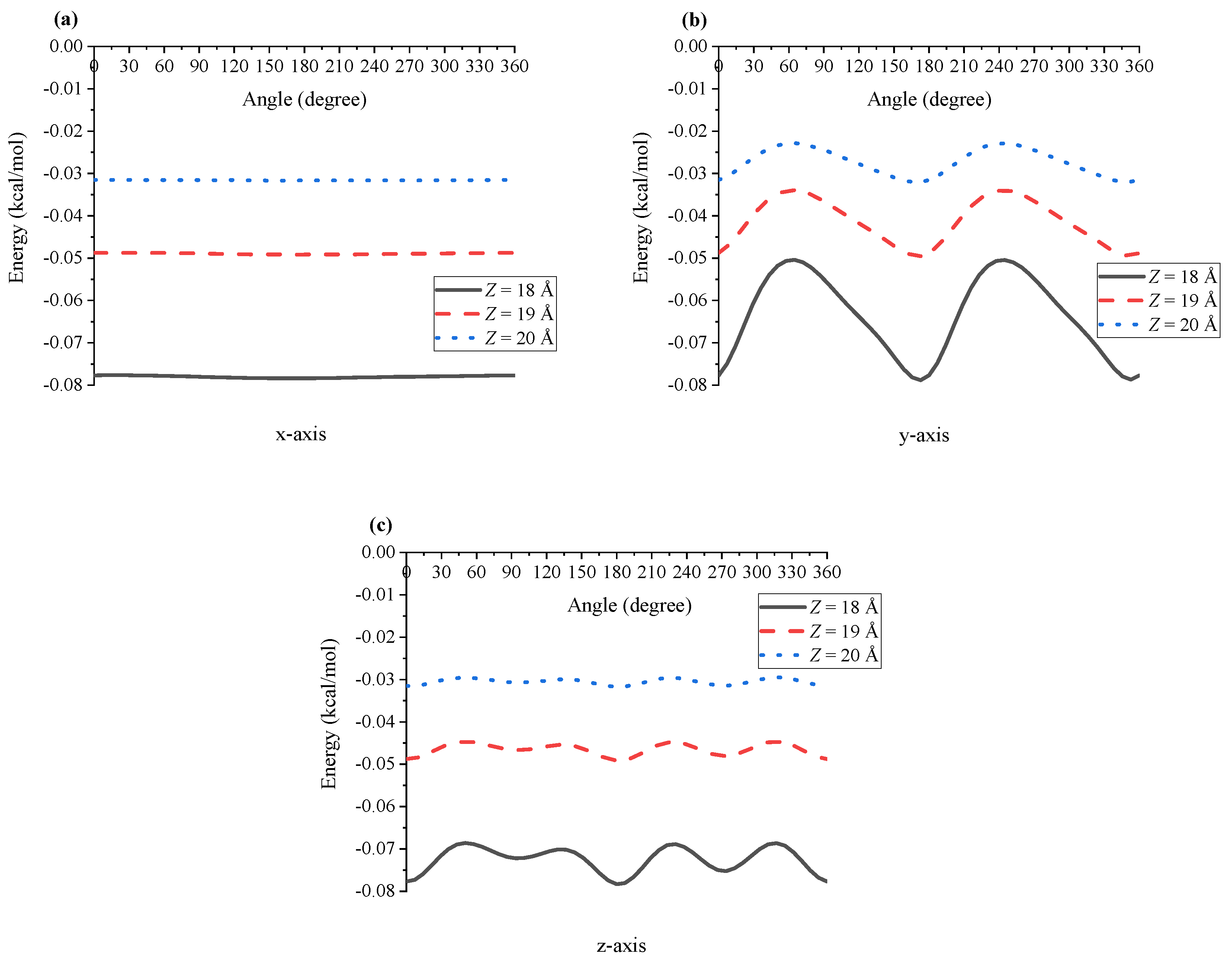
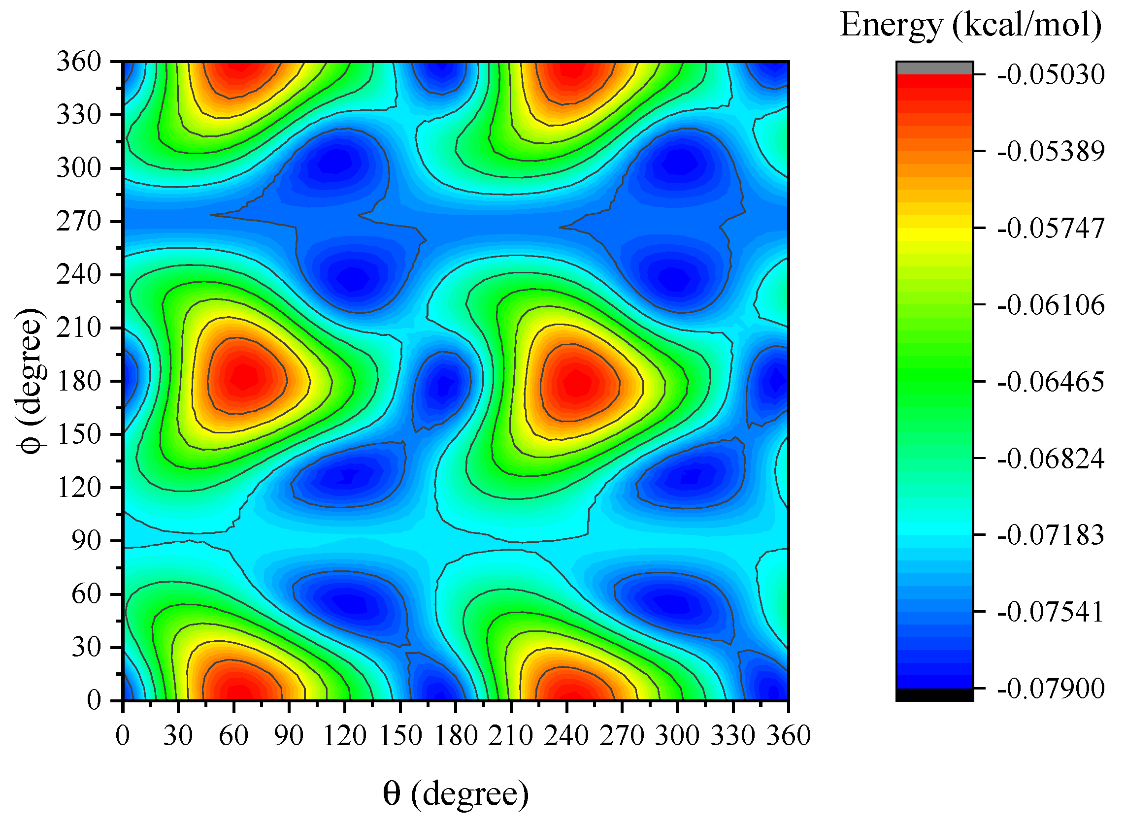
4. Results and Discussion
5. Summary
Author Contributions
Funding
Acknowledgments
Conflicts of Interest
Appendix A. Lennard-Jones Constants

| Atomic Type | (kcal/mol) | (Å) |
|---|---|---|
| Ru | 0.056 | 2.6397 |
| N | 0.069 | 3.2607 |
| C | 0.105 | 3.4309 |
| H | 0.044 | 2.5711 |
| Ti | 0.017 | 2.8286 |
| O | 0.060 | 3.1181 |
| A (kcal Å mol) | B (kcal Å mol) | |
|---|---|---|
| C-C | 684.952 | 1.117 × |
| C-H | 198.597 | 1.451 × |
| C-O | 391.383 | 4.825 × |
| C-Ti | 158.824 | 1.493 × |
| H-H | 50.846 | 1.469 × |
| H-O | 108.900 | 5.770 × |
| H-Ti | 42.371 | 1.641 × |
| N-N | 331.715 | 3.987 × |
| N-C | 477.593 | 6.699 × |
| N-H | 135.475 | 8.327 × |
| N-O | 270.913 | 2.852 × |
| N-Ti | 109.126 | 8.693 × |
| Ru-C | 239.856 | 1.876 × |
| Ru-H | 62.110 | 1.943 × |
| Ru-N | 163.944 | 1.081 × |
| Ru-Ti | 51.561 | 2.154 × |
| Ru-O | 132.017 | 7.517 × |
| Ru-Ru | 75.789 | 2.564 × |
Appendix B. Interaction Energy between Dye and Semiconductor Obtained by Model I
- (i)
- atom and N layer:
- (ii)
- atom interacting with spherical shell of C (with thickness ):
- (iii)
- atom and H layer:
- (iv)
- Two N layers:
- (v)
- N layer and spherical shell of C:
- (vi)
- N layer and H layer:
- (vii)
- Two spherical shells of C:
- (viii)
- H layer and spherical shell of C:
- (ix)
- Two H layers:
- (I)
- atom and sphere:
- (II)
- N layer and sphere:
- (III)
- Spherical shell of C and sphere:
- (IV)
- H layer and sphere:
Appendix C. Configurations between Dye-Dye and Dye-TiO2 Molecules


References
- Maldon, B.; Thamwattana, N. An analytical solution for charge carrier densities in dye-sensitized solar cells. J. Photochem. Photobiol. A Chem. 2019, 370, 41–50. [Google Scholar] [CrossRef]
- Maldon, B.; Thamwattana, N.; Edwards, M. Exploring nonlinear diffusion equations for modelling dye-Sensitized solar cells. Entropy 2020, 22, 248. [Google Scholar] [CrossRef]
- Kalyanasundaram, K. Photophysics, photochemistry and solar energy conversion with tris(bipyridyl)ruthenium(II) and its analogues. Coord. Chem. Rev. 1982, 46, 159–244. [Google Scholar] [CrossRef]
- Juris, A.; Balzani, V. Ru(II) polypyridine complexes: Photophysics, photochemistry, electrochemistry, and chemiluminescence. Coord. Chem. Rev. 1988, 84, 85–277. [Google Scholar] [CrossRef]
- Campagna, S.; Puntoriero, F.; Nastasi, F.; Bergamini, G.; Balzani, V. Photochemistry and photophysics of coordination compounds: Ruthenium. Top. Curr. Chem. 2007, 280, 117–214. [Google Scholar]
- Seidel, R.; Faubel, M.; Winter, B.; Blumberger, J. Single-ion reorganization free energy of aqueous Ru(bpy) and Ru(H2O) from photoemission spectroscopy and density functional molecular dynamics simulation. J. Am. Chem. Soc. 2009, 131, 16127–16137. [Google Scholar] [CrossRef]
- Diamantis, P.; Gonthier, J.F.; Tavernelli, I.; Rothlisberg, U. Study of the redox properties of singlet and triplet tris(2,2′-bipyridine)ruthenium(II) ([Ru(bpy)3]2+) in aqueous solution by full quantum and mixed quantum/classical molecular dynamics simulations. J. Phys. Chem. B 2014, 118, 3950–3959. [Google Scholar] [CrossRef]
- Duan, L.; Xu, Y.; Zhang, P.; Wang, M.; Sun, L. Visible light-driven water oxidation by a molecular ruthenium catalyst in homogeneous system. Inorg. Chem. 2010, 49, 209–215. [Google Scholar] [CrossRef]
- Xu, Y.; Duan, L.; Tong, L.; Åkermark, B.; Sun, L. Visible light-driven water oxidation catalyzed by a highly efficient dinuclear ruthenium complex. Chem. Commun. 2010, 46, 6506–6508. [Google Scholar] [CrossRef]
- Kärkäs, M.D.; Åkermark, T.; Johnston, E.V.; Karim, S.R.; Laine, T.M.; Lee, B.L.; Åkermark, T.; Privalov, T.; Åkermark, B. Water oxidation by single-site ruthenium complexes: Using ligands as redox and proton transfer mediators. Angew. Chem. Int. Ed. 2012, 51, 11589–11593. [Google Scholar] [CrossRef]
- Lewandowska-Andralojc, A.; Polyansky, D.E.; Zong, R.; Thummel, R.P.; Fujita, E. Enabling light-driven water oxidation via a low-energy RuIV=O intermediate. Phys. Chem. Chem. Phys. 2013, 15, 14058–14068. [Google Scholar] [CrossRef]
- Kärkäs, M.D.; Verho, O.; Johnston, E.V.; Åkermark, B. Artificial photosynthesis: Molecular systems for catalytic water oxidation. Chem. Rev. 2014, 114, 11863–12001. [Google Scholar] [CrossRef]
- Shylin, S.I.; Pavliuk, M.V.; D’Amario, L.; Fritsky, I.O.; Berggren, G. Photoinduced hole transfer from tris(bipyridine)ruthenium dye to a high-valent iron-based water oxidation catalyst. Faraday Discuss. 2019, 215, 162–174. [Google Scholar] [CrossRef]
- Cassone, G.; Calogero, G.; Sponer, J.; Saija, F. Mobilities of iodide anions in aqueous solutions for applications in natural dye-sensitized solar cells. Phys. Chem. Chem. Phys. 2018, 20, 13038–13046. [Google Scholar] [CrossRef]
- Cassone, G.; Chillé, D.; Foti, C.; Giuffré, O.; Ponterio, R.C.; Sponer, J.; Saija, F. Stability of hydrolytic arsenic species in aqueous solutions: As3+vs. As5+. Phys. Chem. Chem. Phys. 2018, 20, 23272–23280. [Google Scholar] [CrossRef]
- Park, N.G.; van de Lagemaat, J.; Frank, A.J. Comparison of dye-sensitized rutile- and anatase-based TiO2 solar cells. J. Phys. Chem. B 2000, 104, 8989–8994. [Google Scholar] [CrossRef]
- Van de Lagemaat, J.; Benkstein, K.D.; Frank, A.J. Relation between Particle Coordination Number and Porosity in Nanoparticle Films: Implications to Dye-Sensitized Solar Cells. J. Phys. Chem. B 2001, 105, 12433–12436. [Google Scholar] [CrossRef]
- Benkstein, K.D.; Kopidakis, N.; van de Lagemaat, J.; Frank, A.J. Influence of the Percolation Network Geometry on Electron Transport in Dye-Sensitized Titanium Dioxide Solar Cells. J. Phys. Chem. B 2003, 107, 7759–7767. [Google Scholar] [CrossRef]
- Tan, B.; Wu, Y. Dye-sensitized solar cells based on anatase TiO2 nanoparticle/nanowire composites. J. Phys. Chem. B 2006, 110, 15932–15938. [Google Scholar] [CrossRef]
- Angelis, F.D.; Fantacci, S.; Selloni, A. Alignment of the dye’s molecular levels with the TiO2 band edges in dye-sensitized solar cells: A DFT-TDDFT study. Nanotechnology 2008, 19, 424002. [Google Scholar] [CrossRef]
- Mosconi, E.; Yum, J.H.; Kessler, F.; García, C.J.G.; Zuccaccia, C.; Cinti, A.; Nazeeruddin, M.K.; Grätzel, M.; Angelis, F.D. Cobalt electrolyte/dye interactions in dye-sensitized solar cells: A combined computational and experimental study. J. Am. Chem. Soc. 2012, 134, 19438–19453. [Google Scholar] [CrossRef] [PubMed]
- Fazli, F.I.M.; Ahmad, M.K.; Soon, C.F.; Nafarizal, N.; Suriani, A.B.; Mohamed, A.; Mamat, M.H.; Malek, M.F.; Shimomura, M.; Murakami, K. Dye-sensitized solar cell using pure anatase TiO2 annealed at different temperatures. Optik 2017, 140, 1063–1068. [Google Scholar] [CrossRef]
- Liu, J.; Luo, J.; Yang, W.; Wang, Y.; Zhu, L.; Xu, Y.; Tang, Y.; Hu, Y.; Wang, C.; Chen, Y.; et al. Synthesis of single-crystalline anatase TiO2 nanorods with high-performance dye-sensitized solar cells. J. Mater. Sci. Technol. 2015, 31, 106–109. [Google Scholar] [CrossRef]
- Chu, L.; Qin, Z.; Zhang, Q.; Chen, W.; Yang, J.; Yang, J.; Li, X. Mesoporous anatase TiO2 microspheres with interconnected nanoparticles delivering enhanced dye-loading and charge transport for efficient dye-sensitized solar cells. Appl. Surf. Sci. 2016, 360, 634–640. [Google Scholar] [CrossRef]
- Cui, Y.; He, X.; Zhu, M.; Li, X. Preparation of anatase TiO2 microspheres with high exposure (001) facets as the light-scattering layer for improving performance of dye-sensitized solar cells. J. Alloys Compd. 2017, 694, 568–573. [Google Scholar] [CrossRef]
- Girifalco, L.A.; Hodak, M.; Lee, R.S. Carbon nanotubes, buckyballs, ropes, and a universal graphitic potential. Phys. Rev. B 2000, 62, 13104–13110. [Google Scholar] [CrossRef]
- Cox, B.J.; Thamwattana, N.; Hill, J.M. Mechanics of atoms and fullerenes in single-walled carbon nanotubes. I. Acceptance and suction energies. Proc. R. Soc. A 2007, 463, 461–476. [Google Scholar] [CrossRef]
- Hilder, T.M.; Hill, J.M. Continuous versus discrete for interacting carbon nanostructures. J. Phys. A Math. Theor. 2007, 40, 3851–3868. [Google Scholar] [CrossRef]
- Baowan, D.; Cox, B.J.; Hill, J.M. Instability of C60 fullerene interacting with lipid bilayer. J. Mol. Model. 2012, 18, 549–557. [Google Scholar] [CrossRef]
- Rahmat, F.; Thamwattana, N.; Cox, B.J. Modelling peptide nanotubes for artificial ion channels. Nanotechnology 2011, 22, 445707. [Google Scholar] [CrossRef]
- Baowan, D.; Peuschel, H.; Kraegeloh, A.; Helms, V. Energetics of liposomes encapsulating silica nanoparticles. J. Mol. Model. 2013, 19, 2459–2472. [Google Scholar] [CrossRef] [PubMed]
- Baowan, D.; Thamwattana, N. Modelling selective separation of trypsin and lysozyme using mesoporous silica. Microporous Mesoporous Mater. 2013, 176, 209–214. [Google Scholar] [CrossRef]
- Diebold, U. The surface science of titanium dioxide. Surf. Sci. Rep 2003, 48, 53–229. [Google Scholar] [CrossRef]
- Wang, Y.; Zhang, R.; Li, J.; Li, L.; Lin, S. First-principles study on transition metal-doped anatase TiO2. Nanoscale Res. Lett. 2014, 9, 46. [Google Scholar] [CrossRef] [PubMed]
- Jia, J.; Yamamoto, H.; Okajima, T.; Shigesato, Y. On the crystal structural control of sputtered TiO2 thin films. Nanoscale Res. Lett. 2016, 11, 324. [Google Scholar] [CrossRef]
- Rappé, A.K.; Casewit, C.J.; Colwell, K.S.; III, W.A.G.; Skiff, W.M. UFF, a Full Periodic Table Force Field for Molecular Mechanics and Molecular Dynamics Simulations. J. Am. Chem. Soc. 1992, 114, 10024–10035. [Google Scholar] [CrossRef]
- LAMMPS Molecular Dynamics Simulator. Available online: https://lammps.sandia.gov (accessed on 1 July 2019).
- Plimpton, S. Fast Parallel Algorithms for Short-Range Molecular Dynamics. J. Comp. Phys. 1995, 117, 1–19. [Google Scholar] [CrossRef]
- Hirschfelder, J.O.; Curtiss, C.F.; Bird, R.B. Molecular Theory of Gases and Liquids; Wiley: New York, NY, USA, 1954. [Google Scholar]


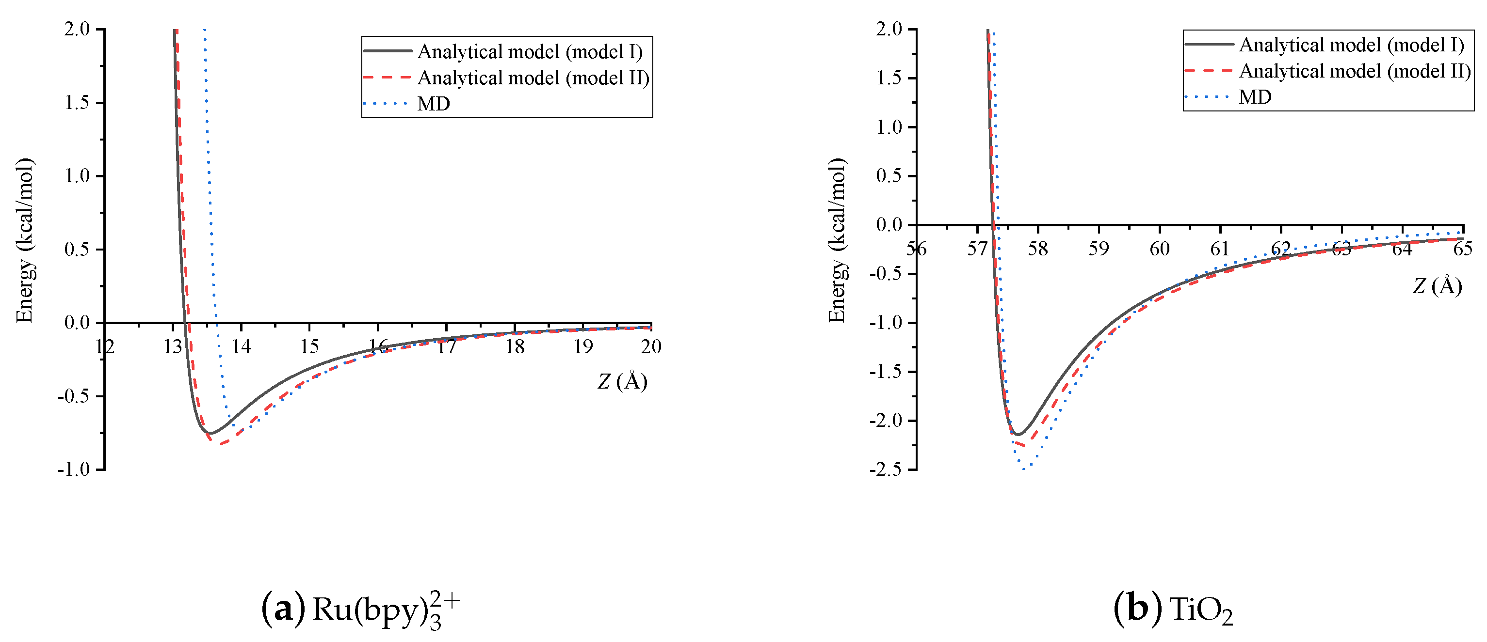
| Z (Å) | (kcal/mol) | (kcal/mol) | (kcal/mol) |
|---|---|---|---|
| 14 | −0.60734 | −0.73692 | −0.73387 |
| 15 | −0.31122 | −0.38330 | −0.38954 |
| 16 | −0.17442 | −0.20862 | −0.20240 |
| 17 | −0.10536 | −0.12263 | −0.11636 |
| 18 | −0.06718 | −0.07649 | −0.07140 |
| Z (Å) | (kcal/mol) | (kcal/mol) | (kcal/mol) |
| 57.75 | −2.12208 | −2.25520 | −2.50002 |
| 59.5 | −0.87185 | −0.94729 | −0.92917 |
| 60 | −0.69583 | −0.75015 | −0.70249 |
| 60.5 | −0.56526 | −0.60502 | −0.54128 |
| 61 | −0.46601 | −0.49565 | −0.42338 |
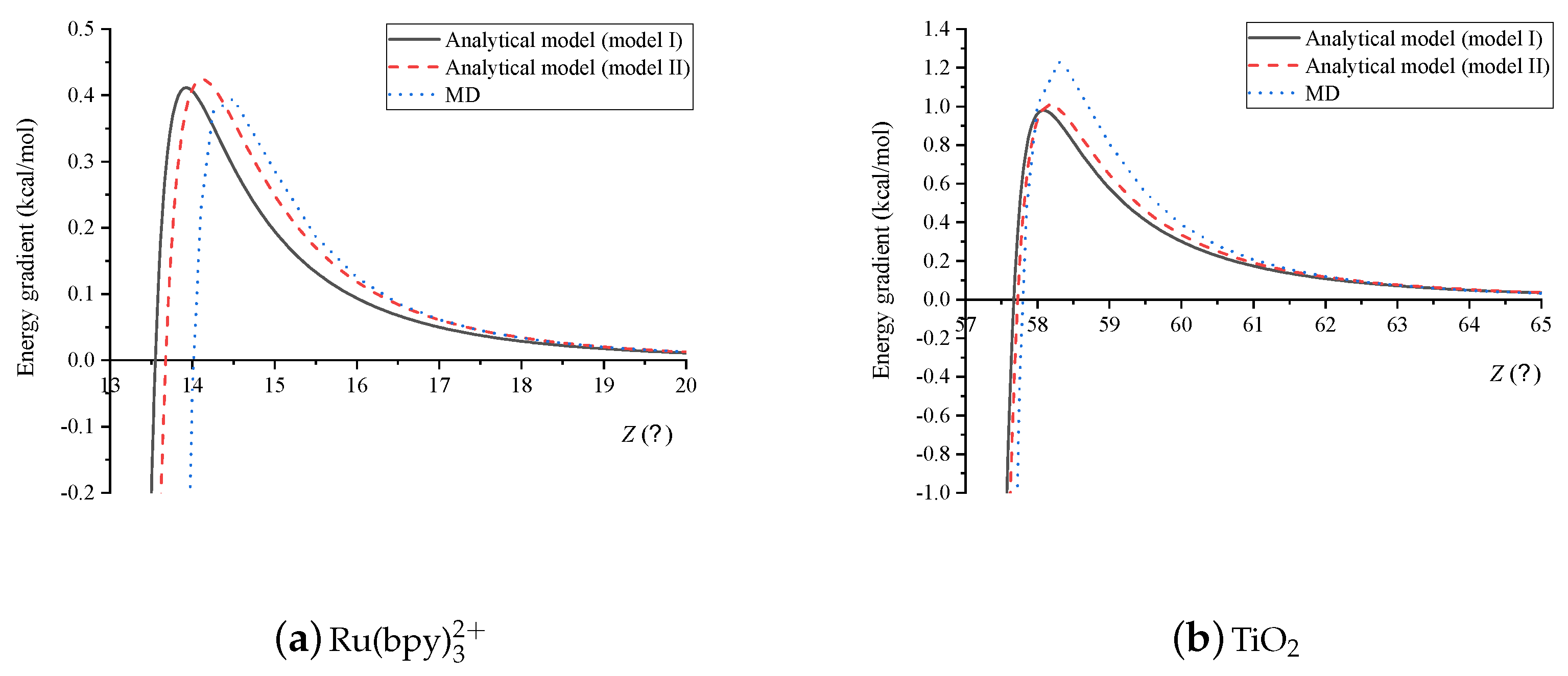
| Dye-Dye | (Å) | (Å) |
|---|---|---|
| Model I | 13.18 | 13.54 |
| Model II | 13.24 | 13.66 |
| MD | 13.52 | 14.00 |
| Dye-TiO | (Å) | (Å) |
| Model I | 57.25 | 57.68 |
| Model II | 57.27 | 57.72 |
| MD | 57.34 | 57.75 |
© 2020 by the authors. Licensee MDPI, Basel, Switzerland. This article is an open access article distributed under the terms and conditions of the Creative Commons Attribution (CC BY) license (http://creativecommons.org/licenses/by/4.0/).
Share and Cite
Putthikorn, S.; Tran-Duc, T.; Thamwattana, N.; Hill, J.M.; Baowan, D.
Interacting Ru(bpy)
Putthikorn S, Tran-Duc T, Thamwattana N, Hill JM, Baowan D.
Interacting Ru(bpy)
Putthikorn, Sasipim, Thien Tran-Duc, Ngamta Thamwattana, James M. Hill, and Duangkamon Baowan.
2020. "Interacting Ru(bpy)
Putthikorn, S., Tran-Duc, T., Thamwattana, N., Hill, J. M., & Baowan, D.
(2020). Interacting Ru(bpy)