Abstract
In this paper, the optimal design of the Flux-Switching Generator with ferrite magnets based on a two-mode substituting load profile for a gearless wind generator is considered. A one-criterion Nelder-Mead method is used to optimize the generator design. The optimization function is constructed mainly so as to minimize the average losses in the generator and the required AC–DC converter power. Also, the Flux-Switching Generator torque-ripple and the ferrite magnets volume are minimized. Using substituting profiles instead of initial ones reduces the calculation efforts substantially. The paper contains the analysis of the optimal design of the Flux-Switching Generator with ferrite magnets.
1. Introduction
Recently many research works have been focused on the optimization of permanent magnet synchronous generators (PMSG) for wind industry. Most often the traditional design with magnets in the rotor is considered in the case of gearless wind turbines.
For example, the optimization routine of a direct drive PMSG with rated values of 500 kW and 36 rpm is presented in Reference [1]. In that work the annual energy production (AEP) is used as the optimization criterion. The calculations are carried out considering eight operating modes of the generator at various wind speeds. It is emphasized that the optimization routine that considers such a large number of the operating points is very computationally demanding and may require the use of distributed parallel or cloud computing.
In Reference [2], another optimization procedure demonstrated by an example of PMSG with rated values of 2 kW and 250 rpm is presented. In this case, ten various operating points of the generator were considered. A multi-objective criterion optimization implemented with help of a genetic algorithm is introduced to maximize AEP, minimize permanent magnet volume and the cost of active materials of the generator.
Another example of applying a multicriteria optimization routine to enhance the performances of PMSG of a large rated power is demonstrated in Reference [3]. In that case, AEP, overall weight of the generator and the cost of the active materials are considered as the objectives. Ten generator operating points are considered in the optimization routine.
Also, it should be mentioned that the approaches similar to those described above are used in several other studies [4,5,6].
Therefore, based on the above literature analysis [1,2,3,4,5,6], we can conclude that the annual energy production is often used as the objective to enhance the generator energy efficiency considering the entire working cycle of the wind turbine. However, the considered approaches require consideration of a large number of the operating points in the optimization routine and are therefore very computationally demanding.
A novel approach has been proposed in Reference [7] to reduce the computational cost when optimizing AEP of the generator. It is suggested to use the equivalent load profiles consisting of a significantly reduced number of operating points (2 or 3) that substitute the initial load profile of the wind turbine. The proposed approach can be used both in the case of discrete load profiles consisting of a finite number of operating points (more than two) and in the case of continuous profiles to be discretized.
Since the computational cost can be reduced significantly compared with the traditional techniques [1,2,3,4,5,6], it is prospective to use the proposed approach when optimizing various types of electric machines.
The proposed approach of constructing the substituting load profiles making it possible to lower the computational cost was demonstrated using an example of an innovate type of wind generators with magnets on the stator [7]. The following criteria are used for its optimization: the average power losses in the generator, the cost of permanents magnets and the required AC–DC converter (active rectifier) power. An example considered in that work includes the initial wind turbine load profile consisting of 9 operational modes [8]. The two-point and three-point substituting profiles are used to replace the initial profile.
In Reference [7], design features of Flux-Switching Generator (FSG) with Nd-Fe-B magnets found out as a result of the optimization process are described. Among them there is the trapezoidal form of the stator teeth thinning near its base. It is shown that the average generator losses obtained using the two-point, the three-point and the initial nine-point load profiles match accurately that gives a good verification of the proposed approach for the optimization of the FSG with Nd-Fe-B magnets.
Nowadays, the rapid development of wind generators containing rare-earth permanent magnets is seen in the world. In the other hand, the rare-earths are costly, and their production is harmful to the environment [9,10].
Besides, the costs of the rare-earth elements for the magnets production are not stable and can be changes by several times for several years [5,6]. Therefore, a good alternative for the FSG with rare-earth magnets is FSG with ferrite magnets. Ferrite magnets are several times cheaper than rare-earth ones and the extraction of raw materials for their production, as well as their production, exist in many countries of the world [11].
However, the remanent flux of ferrite magnets is several times less than that of rare-earth magnets [11,12]. Therefore, the design of FSG with the include ferrite magnets can have their distinguishing features compared to a FSG with rare-earth magnets.
In this paper, the optimal design of the FSG with ferrite magnets based on the two-mode substituting load profile for a gearless wind generator is considered. It is shown that unlike FSG with rare-earth magnets [7], at making up the objective function to optimize FSG with ferrite magnets, the merit of the criterion of decreasing the reactive power must be significantly increased.
The design optimization of flux switching generators with ferrite magnets is described in several papers [13,14]. In Reference [13], the generator efficiency over a wide range of operating modes is taken into account. However, the generator power factor which is also important since it affects the AC–DC converter cost is not considered. In addition, the proposed approach is very computationally demanding since it requires considering a large number of operating points of the generator and solving the correspondent number of boundary problems at each stage.
In Reference [14], a genetic algorithm is used. The weight of active materials, torque ripple, efficiency and power factor of the generator were chosen as the objectives. However, only the rated load mode is considered because of the high computational burden of the genetic algorithm applied.
In Reference [7] the optimization of flux switching generator is considered with a reduced computational cost taking into account a large number of the operating points. However, features of the optimization process of FSG with ferrite magnets that are noticed in Reference [12] are not considered.
In the current paper, a novel optimization method for flux switching generators with ferrite magnets is proposed taking into account such objectives as the efficiency of the generator at several operational points, required power of the AC–DC converter, torque ripple, amount of ferrite magnets. This method also reduces significantly the computational cost comparing with ones proposed in References [13,14].
2. Construction of Two-Mode Substituting Load Profile of Wind Turbine
This paper describes the optimal designing of the FSG for the wind turbine operating at the wind speed range from 4 to 12 MPS (meter per second) [8]. The turbine rotational speeds, its powers and torques at nine maximum operating points corresponding to the wind speeds from this range are given in Table 1. It is assumed that the FSG does not run when the wind speed is out of this range.

Table 1.
The operating points of the wind generator.
The year wind speed distribution is often approximated by the one-parameter Rayleigh distribution [15]. In this paper the average wind speed is assumed to be 7 MPS. Since the wind speeds of the given nine modes are integers, the probabilities of these modes are assumed to be equal to the Rayleigh distribution density at the given wind speed. The column pi in Table 1 provides the conditional probabilities estimated by normalizing the probabilities of the nine modes so that their sum is equal to 1.
Figure 1 shows the dependence of torque on speed at the maximum power curve of the wind turbine obtained by interpolating the date from Table 1 with a cubic polynomial using the least squares method (“cftool” Matlab toolbox). The adjusted R-square is 0.9997.
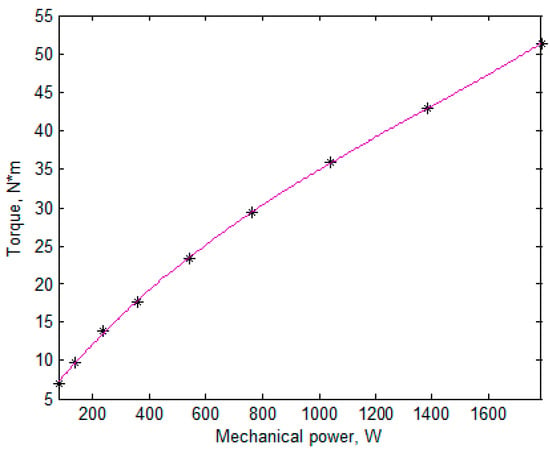
Figure 1.
Loading torque profile of the wind turbine.
It is assumed in Reference [7] that the averages of various random values can be interpolated by n-th degree polynomials of the turbine mechanical power Pmech. The substituting load profile is built so that its averages coincide with that calculated over the original profile, which results in the coincidence of the averages of the polynomial interpolated values over the original and substituting load profiles. The rated mode with highest power is necessarily included in the substituting mode because it determines the required converter power used as one of the optimization objectives. Other modes of the substituting profile are characterized by two parameters: by the probability and the mechanical power determining the point on the turbine’s maximum power curve (Figure 1). So, in m-mode substituting load profile, (m-1) modes can be adjusted and the polynomial degree becomes 2∙(m-1). For example, when the values are accurately interpolated by quadric polynomial, the two-mode substituting profile is sufficient.
Table 2 shows the substituting two-mode load profile of the wind turbine.

Table 2.
The two-mode substituting profile.
Initial substituting profile [7,8] contains 9 modes while the substituting profile does only two ones which reduces the calculation efforts by 4.5 times.
3. Optimization Objectives
There are four optimization objectives in this research. The first one is the reduction of the average losses in FSG K1 = < Ploss >, where < > denotes averaging. To reduce calculation efforts, this average is taken over the two-mode substituting load profile. K1 is aimed to increase the generator output. Second criterion K2 is to reduce the required power of the AC–DC converter (active rectifier consisting of 6 Insulated-Gate Bipolar Transistors switches with Pulse Width Modulation):
where Iampl,rated and UDC,rated are the current amplitude and the required DC voltage (the amplitude value of the FSG line voltage) of the AC–DC converter required at the rated conditions (T = 100%, n = 100%), that is, when these parameters reach their maximum values. Pconv coincides with the apparent power when the current and the voltage are sinusoidal and symmetric, and is expressed through UDC,rated, which is the converter limitation. In contrast to a motor, in a generator, the losses make active power lower than mechanical power, which can lead to the reduction of the required AC–DC converter power Pconv. So, in the case of generator, the gain in the objective function (3) can be obtained due to an increase in the FSG losses. To avoid this effect, Iampl,rated and UDC,rated in (1) are to be calculated without taking into account the losses in the FSG. This means that criterion K2 is insensitive to an increase in the required AC–DC converter power due to a decrease in the losses in the FSG. The expression for K2 is
where Iampl,rated,0 and UDC,rated,0 are the current amplitude and the required DC voltage of the AC–DC converter required at the rated conditions (T = 100%, n = 100%) calculated without taking into account the losses in the FSG.
The third objective is determined by expression K3 = L∙(hmagn + 0.001 m)∙lmag, where lmag = R1 − R3 − 2∙Δ3 is the radial length of the magnets. K3 is to decrease the cost of the magnets and is similar to the volume, that is, equal to the product of three dimensions of the magnets but the magnet thickness is increased by 0.001 m (meter) to take into account that thin magnets cost more per kg than thick ones [16].
The fourth objective K4 is the average of the relative value of the peak-to-peak torque ripple which is also taken over the two-mode substituting profile.
4. Initial Design FSG with Ferrites Magnets
The main geometric dimensions of the FSG are given in Figure 2. The FSG parameters fixed during the optimization are given in Table 3. The parameters α1 and α2 are given in the stator tooth pitch, ts = 360°/24 = 15° and the angular size of the rotor teeth are given in the rotor tooth pitch, tr = 360°/22 = 16.4°. Table 4 shows the parameters that varied during the optimization. To reduce the reactive power, the current angle varied. The current angle was assumed to be proportional to the torque; the zero angle of the current corresponds to the maximum torque when the current is small and does not influence the steel saturation.
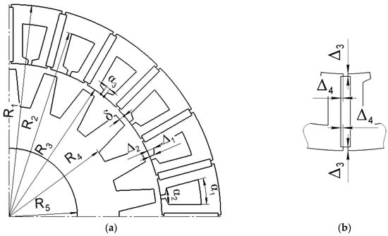
Figure 2.
Optimization parameters: (a) 1/4 cross-sectional area of Flux-Switching Generator (FSG); (b) stator tooth.

Table 3.
The fixed FSG parameters during the optimization.

Table 4.
The varied FSG parameters during the optimization.
The remanent flux of ferrite magnets is 0.35–0.4 T while that of rare-earth magnets (NdFeB) reaches 1.2–1.3 T. Therefore, FSG with ferrite magnets must have larger sizes than that with rare-earth magnets. Particularly, the inner stator diameter R3 must be increased. Besides, to collect required flux, it is necessary to increase the magnets’ areas transversal to the flux, that is, to increase the stack length L and radial length of the magnets ≈ R1 − R3.
The magnetic flux in the air gap is determined not only by magnets remanent flux and their aria transversal to the flux but also the reluctance of the parts of the magnetic circuit. An increase in this aria and rather high permeability (µ) of ferrite magnets (µ = 1.11 for ferrite magnets and µ = 1.03 for rare-earth magnets) are the factors decreasing their reluctance. Therefore, despite increased size of the FSG with ferrite magnets, increasing the air gap is not desirable.
Also, despite increased sizes of FSG and its magnets, the magnetic flux induced by the magnets in FSG with ferrite magnets is expected to be lower than that in FSG with rare-earth magnets. Therefore, to obtain the same power, the slot current is to be increased, which together with decreased reluctance of the magnetic circuit results in increasing reactive power and decreasing the power factor of the FSG with ferrite magnet.
The decrease in the magnetic circuit reluctance and the probability of the magnet demagnetization can be mitigated by increasing the thickness of the magnets, which results in a decrease in the slot thickness (parameters α1 and α2), an increase in the slot leakage and reactive power. Therefore, whereas in the FSG with neodymium magnets, the stator yoke is rather saturated, it is expected to be unsaturated and to have a superfluous thickness in the case of FSG with ferrite magnets.
Table 3 and Table 4 provide the values of the fixed and varied parameters for the initial design of the FSG with ferrite magnets. Those parameters for FSG with rare-earth magnets [7] are also given as an example.
Some parameters of the initial design of the FSG is as follows: Pconv = 3.86 kW, K2 = 3.67 kW, K1 = 106 W, its efficiency is 80.3%, K4 = 4.7%. Hence, the initial design has rather high efficiency and low torque ripple but the required AC–DC converter power is unacceptably high. More information on the initial design is in Table 5.

Table 5.
FSG objectives at various stages of optimization.
Figure 3 shows the magnitude of the magnetic flux density of the FSG at two modes of the substituting load profile. Although the remanent flux density of ferrite magnets is only 0.4 T, the flux concentration effect results in rather high values of magnetic flux density (there are rather large areas with flux density over 1.2 T) even at underload mode.

Figure 3.
The plot of the flux density magnitude in the initial FSG design: (a) underload mode of the two-mode profile; (b) rated mode.
In FSG with rare-earth magnets, the flux was created mainly by magnets and the flux densities in two modes of the two-mode substituting profile almost coincided. In contrast, in FSG with ferrite magnets, the rated mode is much more saturated than the underloaded one. The magnetic flux of the winding current produces reactive power, which increases the required AC–DC converter power. The required AC–DC converter power is the most significant problem to solve at designing a FSG, which is demonstrated below.
5. Optimization FSG with Ferrite Magnets and its Results
A multi-objective optimization is widely used in designing an electrical machine [17].
Some multi-objective methods are aimed to build the Pareto front, that is, the set of the solutions in which no objective can be improved without worsening other objectives. In this case, an engineer chooses such a solution among the Pareto front in which the objectives reach their values according to their merits in the given task. Usually, such an approach requires a large number of function calls (3000 as reported in Reference [17]).
Another approach to multi-objective optimization is implemented on the basis of one-criterion methods of optimization. In this case, the objectives merits should be set to construct the optimization criterion as a function of these objectives.
So, in any case, the importance of the objectives must be assigned either at the optimization beginning or at its end.
To reduce the calculation efforts, the multi-objective optimization implemented on the basis of the one-criterion Nelder–Mead method is used in the paper. Such an approach for the optimization of the high-speed single-phase flux reversal machine developed in Reference [18] requires only 115 function calls. In contrast, the approach based on a genetic algorithm, described in Reference [17] requires 3000 function calls, which is 26 times higher.
Nelder-Mead method was used in design optimization of several electrical machines [7,19]. In Reference [19], rated motor efficiency much higher than IE5 efficiency class level (according to IEC 60034–30-2 “Rotating electrical machines-Part 30-2: Efficiency classes of variable speed AC motors (IE-code)”) was obtained using Nelder–Mead method. In addition, other important characteristics of the motor included in the objective function such as torque ripple and efficiency at underload were improved.
Therefore, Nelder-Mead method does not provide with assurance the global optimum but the method makes it possible to find good practical solutions with a reduced computational cost. For this reason, in this work, Nelder-Mead method and the objective function (3) are used.
In this paper, the optimization is carried out in three stages. First two stages are tentative and have only 56 and 46 objective function calls. The rest stage has 95 objective function calls. The Nelder-Mead method is used at each stage.
The objective function is constructed so as to make K3 and K4 the most insignificant objectives because of cheapness of ferrite magnets and low torque ripple in the initial design. Namely, decreasing K3 and K4 by 10% is assumed to be as valuable as decreasing K1 by 1%. The objective function is as follows:
The parameter z determines the merit of the criterion K2. Since the required AC–DC converter power of the initial design is too high, K2 is the most valuable objective. At first stage, z = 2, which means that decreasing K2 by 0.5% is as valuable as decreasing K1 by 1%.
The merit of K2 was corrected at each stage with the help of the parameter z. The parameter z increased from stage to stage and took the values 2, 3, 4 until the acceptable values K2 and the power factor greater than 0.75 were obtained. It means that the reduction of the losses in the generator < Ploss > by 1% is as valuable as the reduction of the required AC–DC converter power by 1/3% at the second stage and by 0.25% at the third stage.
The weight of the electric generator is only about 5%–16% of the overall weight of the wind turbine mast-mounted equipment and much less than the wind turbine overall weight [20]. In addition, the FRG with ferrite magnets that is considered in our paper has much higher specific torque (torque per weight unit) than that of generators without permanent magnets. However, generators without permanent magnets are also used in wind energy applications [21,22]. For this reason, the weight of the generator active materials was not included in the objectives of the optimization function (3).
Changing the main characteristics of the FSG as well as the parameters included in the objective function (3) during the optimization is shown in the Figure 4, Figure 5, Figure 6 and Figure 7. Vertical lines delimitate different stages. Figures show that the scattering of the parameters value becomes lower during the optimization that is the optimization converges.
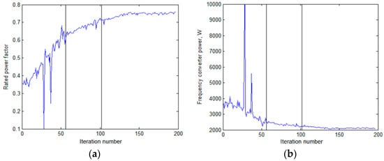
Figure 4.
Changing the parameters during the optimizations: (a) the generator’s power factor; (b) the required AC–DC converter power.
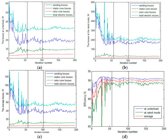
Figure 5.
Changing the following parameters during optimization: (a) various types of losses at the underload; (b) those at the rate mode; (c) the average losses; (d) the FSG’s efficiency.
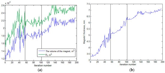
Figure 6.
Changes in the parameters of the magnets during the optimization: (a) the volume of the magnets and the parameter K3; (b) the magnets’ thickness.
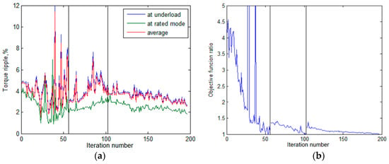
Figure 7.
Changes in the parameters of the magnets during the optimization: (a) the FSG torque ripple; (b) the objective function.
Figure 4 shows changes in the FSG power factor and the required AC–DC converter power. Figure 5 shows changings in various energetic parameters. Figure 6 shows changes in the parameters of the magnets.
The torque ripple change is shown in the Figure 7a. The change in the objective function (3) during optimization is shown in Figure 7b.
Since the objective function changes from the stage to the stage and, consequently, its values change by several times, Figure 7b shows the ratio of the its value to the best value at the given stage. As it can be seen from the figure, the best value is achieved not necessarily in the end of the stage. The geometry of the FSG designs obtained at three stages and the magnetic flux density are shown in Figure 8.
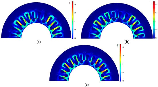
Figure 8.
Changes in the generator geometry during the optimization: (a) stage 1; (b) stage 2; (c) stage 3.
Table 5 shows the main characteristics of the FSG from the stage to the stage. The first stage is most productive: the losses reduced significantly, the efficiency increases both in the rated mode and in the underload mode. The required AC–DC converter power is reduced and the power factor is increased. The further decrease in the required AC–DC converter power was obtained in the second stage. The remained objectives rested almost unchanged. The averaged losses decreased at third stage which is a compromise for decreasing the required AC–DC converter power and the power factor.
Table 6 shows the changes in the main geometric parameters and in the active material masses.

Table 6.
Design parameters.
The magnet’s mass increased significantly during optimization due to their thickness. It is supposed that it affects their const just a little because thin magnets cost more than thick ones per kg.
At optimization stages 1 and 2, the stator slot depth increased, which made it possible to increase the copper mass and, consequently, the efficiency. At stage 3, the stator slot depth decreased because of increased thickness of the yoke, which reduced the slot leakage and increased the power factor. However, this results also in decreased copper mass and efficiency.
6. Results Comparison using the Substituting Two-Mode Profile and the Initial Nine-Mode Profile
Checking the applicability of the two-mode substituting profile was done by comparing the calculation results and that under 9-mode initial profile. Ploss calculated at the modes of the 9-mode profile and 2-mode substituting profiles, as well as its average values over these profiles are given in Table 7. These averages accurately coincide.

Table 7.
The calculated losses of the optimized FSG design.
To explain this excellent coincidence of the averages over the two load profiles, the dependence of the losses on the mechanical power and its approximation by a quadric trinomial obtained with the least square method are given in Figure 9. As it can be seen in Figure 9, the quadric trinomial approximates the dependence very well (the error is less than 0.5%). Therefore, the average losses calculated over the two-mode and nine-mode load profile coincide well.
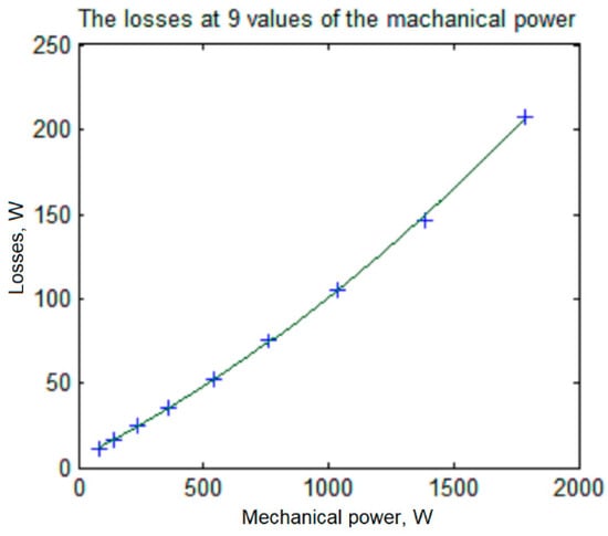
Figure 9.
The calculated losses of the optimized FSG design and their quadric approximation.
7. Conclusions
In this paper, the optimal design of an FSG with ferrite magnets based on a two-mode substituting load profile for a gearless wind generator is considered. A one-criterion Nelder-Mead method is used to optimize the FSG design. The optimization function is constructed mainly so as to minimize the losses in FSG and the required converter power. Also, the FSG torque-ripple and the ferrite magnets volume is minimized. Initial substituting profile contains 9 modes while the substituting profile does only two ones which reduces the calculation efforts by 4.5 times.
The initial design of the FSG with ferrite magnets is a modified design of the FSG with rare-earth ones. Since remanent flux of ferrate magnets is approximately thrice as low as that of rare-earth one, the volume of the FSG with ferrite magnets has increased by 2.1 times.
Obtaining acceptable required converter power and power factor is not easy in FSG with ferrite magnets. Therefore, the optimization was carried out through three stages and the merit of the required AC–DC converter power was adjusted from stage to stage.
To collect the necessary flux, the magnets areas transversal to the flux must be rather large. Although the slot depth increased during the optimization, it cannot be too high and even decreased at the third stage to reduce the slot leakage. Therefore, although the stator yoke is reduced during the optimization it is still overabundant and unsaturated.
The increase in the magnets areas transversal to the flux results in the decrease in their magnetic circuit reluctance. To compensate this effect, the magnets thickness increased.
In future researches, comparison of a FSG with other types of gearless generators (synchronous generator with rare-earth magnets, synchronous reluctance generator with ferrite magnets, flux reversal generator etc.), as well as comparison of the results of the generators optimization obtained with Nelder-Mead method and genetic algorithm are planned.
Author Contributions
Conceptual approach, V.P. and V.D.; data curation V.D. and V.K.; software V.D. and V.P.; calculations and modeling, V.P and V.D. and V.K.; writing of original draft, V.P. and V.D. and V.K.; visualization, V.D. and V.K.; review and editing, V.P. and V.D. and V.K. All authors have read and agreed to the published version of the manuscript.
Funding
The research was conducted on theme no. 8.9549.2017/8.9. within the frame of the government task of the Ministry of Education and Science of the Russian Federation in R&D.
Acknowledgments
The authors thank the editors and reviewers for careful reading, and constructive comments.
Conflicts of Interest
The authors declare no conflict of interest.
References
- Jung, S.; Jung, H.; Hahn, S.; Jung, H.; Lee, C. Optimal Design of Direct-Driven PM Wind Generator for Maximum Annual Energy Production. IEEE Trans. Magn. 2008, 44, 1318–1338. [Google Scholar] [CrossRef]
- Faiz, J.; Ebrahimi, B.; Rajabi-Sebdani, M.; Khan, A. Optimal design of permanent magnet synchronous generator for wind energy conversion considering annual energy input and magnet volume. In Proceedings of the 2009 International Conference on Sustainable Power Generation and Supply, Nanjing, China, 6–7 April 2009; pp. 1–6. [Google Scholar] [CrossRef]
- Isfahani, A.; Boroujerdi, A.; Hasanzadeh, S. Multi-objective design optimization of a large-scale direct-drive permanent magnet generator for wind energy conversion systems. Front. Energy 2014, 8, 182–191. [Google Scholar] [CrossRef]
- Daghigh, A.; Javadi, H.; Torkaman, H. Design Optimization of Direct-Coupled Ironless Axial Flux Permanent Magnet Synchronous Wind Generator with Low Cost and High Annual Energy Yield. IEEE Trans. Magn. 2016, 52, 1–11. [Google Scholar] [CrossRef]
- Daghigh, A.; Javadi, H.; Torkaman, H. Considering Wind Speed Characteristics in the Design of a Coreless AFPM Synchronous Generator. Int. J. Renew. Energy Res. 2016, 6, 263–270. [Google Scholar]
- Ahn, Y.; Park, J.; Lee, C.; Jeong, Y.; Kim, Y.; Jung, S. Optimal Design of Direct-Driven PM Wind Generator Using Memetic Algorithm coupled with FEM. In Proceedings of the 2009 International Conference on Electrical Machines and Systems, Tokyo, Japan, 15–18 November 2009; pp. 1–6. [Google Scholar] [CrossRef]
- Dmitrievskii, V.; Prakht, V.; Kazakbaev, V. Design Optimization of a Permanent-Magnet Flux-Switching Generator for Direct-Drive Wind Turbines. Energies 2019, 12, 3636. [Google Scholar] [CrossRef]
- Anandavel, P.; Rajambal, K.; Chellamuthu, C. Power Optimization in a Grid-Connected Wind Energy Conversion System. In Proceedings of the 2005 International Conference on Power Electronics and Drives Systems, Kuala Lumpur, Malaysia, 28 November–1 December 2005. [Google Scholar] [CrossRef]
- Ault, T.; Krahn, S.; Croff, A. Radiological Impacts and Regulation of Rare Earth Elements in Non-Nuclear Energy Production. Energies 2015, 8, 2066–2081. [Google Scholar] [CrossRef]
- Schulze, R. Reducing Environmental Impacts of the Global Rare Earth Production for Use in Nd-Fe-B Magnets, How Magnetic Technologies Much Can Recycling Contribute? Ph.D. Thesis, Technical University of Darmstadt, Darmstadt, Germany, December 2018. [Google Scholar]
- Dmitrievskii, V.; Prakht, V.; Kazakbaev, V. Synchronous reluctance generator with ferrite magnets for wind turbine. In Journal of Physics: Conference Series; IOP Publishing: Bristol, United Kingdom, 2018; Volume 1102. [Google Scholar] [CrossRef]
- Fasolo, A.; Alberti, L.; Bianchi, N. Performance comparison between switching-flux and IPM machine with rare earth and ferrite PMs. In Proceedings of the 2012 XXth International Conference on Electrical Machines, Marseille, France, 2–5 September 2012. [Google Scholar] [CrossRef]
- Ojeda, J.; Simões, M.; Li, G.; Gabsi, M. Design of a Flux-Switching Electrical Generator for Wind Turbine Systems. IEEE Trans. Ind. Appl. 2012, 48, 1808–1816. [Google Scholar] [CrossRef]
- Akuru, U.; Kamper, M. Intriguing Behavioral Characteristics of Rare-Earth-Free Flux Switching Wind Generators at Small- and Large-Scale Power Levels. IEEE Trans. Ind. Appl. 2018, 54, 5772–5782. [Google Scholar] [CrossRef]
- Pishgar-Komleh, S.; Keyhani, A.; Sefeedpari, P. Wind speed and power density analysis based on Weibull and Rayleigh distributions (a case study: Firouzkooh county of Iran). Renew. Sustain. Energy Rev. 2015, 42, 313–322. [Google Scholar] [CrossRef]
- Hard Ferrite Magnets, IBS Magnet. Available online: https://ibsmagnet.com/products/dauermagnete/hartferrit.php (accessed on 26 December 2019).
- Cupertino, F.; Pellegrino, G.; Gerada, C. Design of synchronous reluctance machines with multiobjective optimization algorithms. IEEE Trans. Ind. Appl. 2014, 50, 3617–3627. [Google Scholar] [CrossRef]
- Dmitrievskii, V.; Prakht, V.; Kazakbaev, V. Optimal design of a high-speed single-phase flux reversal motor for vacuum cleaners. Energies 2018, 11, 3334. [Google Scholar] [CrossRef]
- Dmitriveskii, V.; Prakht, V.; Kazakbaev, V. IE5 Energy-Efficiency Class Synchronous Reluctance Motor with Fractional Slot Winding. IEEE Trans. Ind. Appl. 2019, 55, 4676–4684. [Google Scholar] [CrossRef]
- Semken, R.; Polikarpova, M.; Röyttä, P.; Alexandrova, J.; Pyrhönen, J.; Nerg, J.; Mikkola, A.; Backman, J. Direct-drive permanent magnet generators for high-power wind turbines: Benefits and limiting factors. IET Renew. Power Gener. 2012, 6, 1–8. [Google Scholar] [CrossRef]
- Akuru, U.; Kamper, M. Novel experimentation of a 10 kW geared medium-speed wound-field flux switching wind generator drive. In Proceedings of the 2018 IEEE Energy Conversion Congress and Exposition (ECCE), Portland, OR, USA, 23–27 September 2018. [Google Scholar] [CrossRef]
- Akuru, U.; Kamper, M. Formulation and Multiobjective Design Optimization of Wound-Field Flux Switching Machines for Wind Energy Drives. IEEE Trans. Ind. Electron. 2018, 65, 1828–1836. [Google Scholar] [CrossRef]
© 2020 by the authors. Licensee MDPI, Basel, Switzerland. This article is an open access article distributed under the terms and conditions of the Creative Commons Attribution (CC BY) license (http://creativecommons.org/licenses/by/4.0/).