Abstract
The authors introduce a new controller, aimed at industrial domains, that improves the performance and accuracy of positioning systems based on Stewart platforms. More specifically, this paper presents, and validates experimentally, a sliding mode control for precisely positioning a Stewart platform used as a mobile platform in non-destructive inspection (NDI) applications. The NDI application involves exploring the specimen surface of aeronautical coupons at different heights. In order to avoid defocusing and blurred images, the platform must be positioned accurately to keep a uniform distance between the camera and the surface of the specimen. This operation requires the coordinated control of the six electro mechanic actuators (EMAs). The platform trajectory and the EMA lengths can be calculated by means of the forward and inverse kinematics of the Stewart platform. Typically, a proportional integral (PI) control approach is used for this purpose but unfortunately this control scheme is unable to position the platform accurately enough. For this reason, a sliding mode control (SMC) strategy is proposed. The SMC requires: (1) a priori knowledge of the bounds on system uncertainties, and (2) the analysis of the system stability in order to ensure that the strategy executes adequately. The results of this work show a higher performance of the SMC when compared with the PI control strategy: the average absolute error is reduced from 3.45 mm in PI to 0.78 mm in the SMC. Additionally, the duty cycle analysis shows that although PI control demands a smoother actuator response, the power consumption is similar.
1. Introduction
Contemporary markets tend to constantly increase the number of product variants, and product life cycles are also changing. Demand for product families in small batch sizes is increasing, therefore reconfigurable tooling is becoming a key technology for fulfilling production requirements [1,2,3]. For that reason, Stewart platforms, which provide precise motion in six degrees of freedom, are being introduced in production scenarios where continuous positioning and orientating is required. In addition, parallel robot architectures provide high rigidity, high payload-to-weight-ratio, high positioning accuracy, and low inertia of moving parts subjected to high loads. Compared to anthropomorphic robotic arms, they do not have such a wide range of displacements, but they present higher stiffness and precision as well as a simpler solution to the inverse kinematics equations [4,5]. Previous benefits, in addition to the reduction in hexapod production costs, justify the use of Stewart platforms in industrial applications.
Stewart platforms can be found in different domains, such as machinery [1,6], test beds [7], real-time simulators for vehicles [2,8], and antenna/solar orientation platforms [9,10]. Typically, every arm is controlled by an electro mechanical actuator (EMA), but hydraulic actuators are more suitable for large loads [2,11], and piezoelectric actuators are commonly used in micro- or nano-scale platforms (found in biomedical science, optics, and microscopical devices) [12]. Stewart platforms are frequently used as camera levelling bases in a wide range of applications. These devices can be found in rescue operations, traffic control, identification, surveillance of frontiers, agriculture control and fire detection in forest areas, among others. The use of Stewart platforms for levelling cameras has been introduced in automated non-destructive inspections (NDI) in order to reduce labour costs [13,14]. Thermographic cameras, sensitive to radiation in the infrared spectral range, are frequently used in combination with external thermal stimulation systems. Thermographic inspection is normally conducted statically by setting the infrared camera at a fixed distance from the object [15]. However, this approach is subject to the curvature changes in the object inspected so that the spatial resolution is reduced due to the difference in distance between the camera and the target. A different approach in thermographic NDIs consists of applying the inspection dynamically by moving the sensor over the surface of interest. This approach improves the inspection quality, because it permits the detection of smaller defects, but requires higher performance in positioning control systems. Figure 1 illustrates the influence of using static positioning by means of two infrared radiation (IR) images, only one being properly focused.
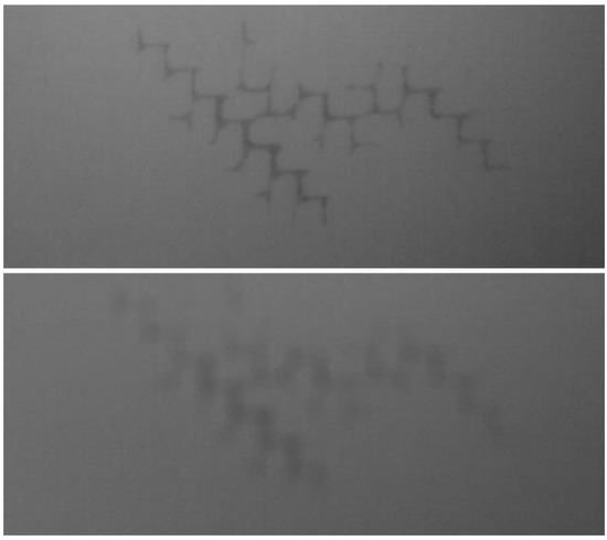
Figure 1.
Comparison between a corrected IR image (above) and a defocused IR image (below).
The control of Stewart platforms must deal with a complex kinetics calculation. It is a well-known fact that, for serial robot manipulators, the solution of a forward kinematics problem is easier than an inverse kinematics problem. However, in parallel robots the situation is just the opposite [4]. Several solutions for the forward and the inverse kinematics are proposed in the literature. The inverse kinematic problem, i.e., obtaining the joint space position or the six link lengths given the position/orientation of the platform or the Cartesian space position, is straightforward to calculate at Stewart Platforms. On the contrary, the forward kinematics problem, viz. the determination of the Cartesian space position for a given joint space position, is more demanding computationally [16]. The most common approach is to calculate the closed-form solution to the inverse kinematic transformation, and then estimate the forward kinematic transformation using the Newton–Raphson method [7]. A different approach for solving the algebraic system of equations utilises the reduced Gröbner basis form of the system of equations under total degree term ordering of its monomials and Sylvester’s Dialytic elimination method [17]. Particle swamp optimisation is another powerful tool that can be used for analysing different robot configurations [18].
In some cases, the kinematic nonlinearity of robotic actuators is a source of error which requires special consideration [3,6]. The use of appropriate algorithms considerably reduces the calculation time of the kinematics, and the use of simulation software is often extended to dynamics modelling (considering the mass and the stiffness of the moving platform and legs) [19,20]. By using a combination of design and finite elements, an integrated approach can be developed that simulates the machine dynamics and solves the kinematics, taking into account rigid body dynamics, vibration and strength [21].
The control strategy must command the actuators to achieve precise positioning, minimise the error, and deal with system uncertainties. A proportional–integral–derivative controller (PID) is a simple closed-loop method to correct uncertainties, the proportional integral (PI) controller version being one of the most popular control approaches in the market. Several control strategies were proposed in the literature to improve the performance of actuators in parallel robot architectures, nevertheless, most of them were validated only through simulations. Among other schemes, the use of inverse models, which represent the behaviour of a system mathematically, may become a simple approach to improve the controller performance when compared to PI controllers. This strategy corrects known nonlinearities in open loop control, even though errors caused by uncertainties and external perturbations are not corrected. The combination of inverse models with feedback controllers [8], such as H-infinity [11] and genetic algorithms [22], enables us to achieve higher accuracy. Another approach is the use of inverse models to condition the closed loop feedback signal [9]. These schemes were validated by simulations.
Sliding mode control (SMC) is a nonlinear control approach that drives the state trajectory of the system onto a specified sliding surface and maintains the trajectory on that surface for the subsequent time under system uncertainties and perturbations. However, in conventional SMC design, a priori knowledge of the bounds on system uncertainties must be acquired [23,24,25]. Several SMC-based strategies to control Stewart platforms are proposed and verified by simulations: SMC with perturbation estimation [26], integral SMC [5], continuous higher order SMC [27], and SMC with fuzzy tuning design [28]. The combination of SMC with estimation techniques, such as state observers [29], allows the conditioning of high frequency input signals [13], and estimating variables when not all states are measured directly, by using super-twisting algorithms [2] and adaptive super-twisting algorithms [10].
This paper presents the development of an SMC aimed at positioning an inspection camera precisely over a Stewart platform. This device is designed to perform inspections on aeronautical coupons, which must fulfil severe quality standards, so that any positioning enhancements leads to substantial improvements in the defect detection ratio. In the literature, the application of SMC in Stewart platforms is validated mainly by simulations. In this study, the proposed SMC strategy is validated experimentally as an alternative to the vendor-provided PI controller, which was producing improperly focused images for the inspection application because it was not accurate enough. The experimental results show that the overall platform performance can be improved by using this control scheme. To develop the SMC strategy, in the first place the inspection platform is analysed and modelled in Section 2, where the inverse and forward kinetics are calculated. Additionally, the system dynamics are modelled in this section, which serve as basis to develop the SMC, in Section 3. The performance of the proposed control scheme is evaluated and compared with the vendor-provided PI controller in Section 4. As a final point, discussion conclusions are presented in Section 5.
2. Stewart Platform Mathematical Modelling
The Stewart platform presented in this paper must be controlled to ensure the position and orientation of an inspection camera. The camera must check different aeronautical samples: several sweep scans at a distance of 40 mm must be performed to ensure the quality of the specimen at different heights. The NDI system is shown in Figure 2a and the trajectory to follow when inspecting the composite panel is shown in Figure 2b.
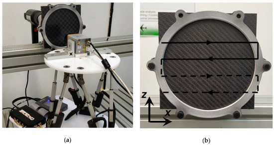
Figure 2.
Inspection system prototype. (a) Test setup; (b) Trajectory scheme.
While recording images, it becomes essential to control the position with the greatest accuracy possible in order to ensure that the camera is on the target, and it is vitally important that the camera remains at a specific distance to the target to avoid defocusing, as shown in Figure 1. In this kind of mechatronic system, an effective control strategy is mandatory to achieve successful positioning, and consequently improve the image quality. To do this, firstly, it is necessary to perform an analysis of the system, and create a mathematical model that represents it, as accurately as possible. Creating the model according to the real needs (open or closed loop control, lifecycle, system instabilities, etc.) is vitally important, so the design is optimized and accurate. In the following subsections, the kinetic modelling and dynamic modelling are presented.
2.1. Platform Kinematics
In order to describe the Stewart platform position and orientation, six coordinates are needed. Three of these coordinates, described by d, are positional displacements that locate the position of a reference point in the moving platform with reference to a fixed coordinate system, selected as the base B. The other three coordinates are angular displacements that describe the orientation of the moving platform, represented as e, again with reference to a nonrotating coordinate system located in the base.
The platform position and orientation are controlled by the length of each actuator li. The calculation of the actuator lengths is required to drive the Stewart platform over a certain trajectory, this operation is done by using the Stewart platform kinematic transformations. Additionally, to develop a successful control strategy, a correct modelling of the system is required. The following subsections describe the inverse and forward kinematics [7,16] as well as the platform model.
2.1.1. Inverse Kinematics
The inverse kinematics determine the required actuator length for achieving a certain position and orientation of the moving platform. Frame assignment for the robot wrist is illustrated in Figure 3, where two coordinate frames, p and B, are assigned to the payload and base platforms, respectively. The Cartesian variables are chosen to be the relative position and orientation of Frame p with respect to Frame B, where the position of Frame p is specified by the position of its origin with respect to Frame B. The position vectors of the centres of spherical joints in frame B and p can be expressed as:
where rB and rP are the radius of the lower and upper platforms, θP = 23° and θB = 96° are the platform and base angles between the first and second joints.
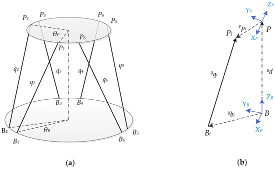
Figure 3.
Stewart platform schemes: (a) Stewart platform frame assignment; (b) vector diagram for the ith actuator.
The leg vector pointing from attachment point Bi to point Pi can be expressed as follows:
where is the orientation matrix required to calculate the platform spherical joint vectors in the base coordinate system used in the rest equation terms.
The length of each actuator can be calculated from the modules of the length vectors :
2.1.2. Forward Kinematics
The forward kinematics allows calculating the platform position and orientation given specific actuator lengths. Equation (9) represents a set of six highly nonlinear simultaneous equations, therefore the Newton–Raphson method can be used to solve the kinematic problem. The objective is to calculate the estimated lengths on an iterative process given an initial position estimation , until the value of , which minimizes the scalar function, is found.
The Newton–Raphson procedure for this case is:
- Select an initial guess (j−1):
- Calculate the rotation matrix , with Equation (8), as the initial guess.
- Calculate with Equation (7) and with Equation (9).
- Calculate the unit vector :
- Compute the inverse Jacobian matrix for the initial guess :
- Compute the estimation :
- If is acceptable, take as the solution, otherwise repeat the procedure with the last estimation.
2.2. Stewart Platform Dynamics
The Stewart platform is moved by means of six EMAs, attached in pairs to three positions on the baseplate of the platform, crossing over to three mounting points on a top plate. The whole system can be divided in six subsystems, each composed of one EMA. In these actuators, the rotary motion of the motor is converted into linear displacements. If the interactions between actuators and external disturbances are considered as perturbations, each EMA can be modelled as a second-order model with a single element, as shown in Figure 4. pest represents the external forces, mi the mass attached to the actuator, bi the friction and ki the actuator stiffness.

Figure 4.
Actuator models. (a) Actuator scheme, (b) actuator mechanical model.
With the proposed scheme, the equation that models the actuator dynamics results is as follows:
where t denotes the time variable. The force applied by the actuator Fi is proportional to the maximum force Fmax and the pulse-width modulation (PMW) duty cycle .
3. Sliding Mode Control Calculation
The control strategy must command each actuator in order to achieve the desired trajectory with a precise platform positioning and orientation, minimizing error and dealing with system uncertainties. The proposed control scheme is shown in Figure 5. The platform setpoint is given in terms of position and orientation (a), so at first the trajectory must be transformed to the equivalent actuator length setpoint (b) by using the inverse kinematics explained in Section 2.1. Then, an SMC closed loop control estimates the voltage outputs (c) that are needed to achieve each actuator length, based on the EMA setpoints (b) and the measured lengths (e). The Stewart platform EMAs are controlled by the SMC voltage input (c) and affected by possible disturbances (e.g., external forces, non-linearities) (d). Finally, the EMA lengths (e) are measured by the encoders and transformed to the equivalent platform position (f), which is done using the forward kinematics shown in Section 2.2. The inverse and forward kinematics have been studied previously, therefore in this section the SMC strategy is developed.
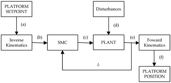
Figure 5.
Stewart platform control scheme. The inverse and forward kinematics are used to calculate the actuator length for a determined platform position, and vice versa. The sliding mode control (SMC) generates the control action to bring the Stewart platform to the desired position.
The Stewart platform native closed loop control was a PI control strategy that provided a stable response. The major drawback of this control was that it did not provide an accurate platform control, therefore the NDI camera produced a low-quality IR image. To improve the positioning accuracy of the platform, an SMC strategy was chosen, because it showed accurate results in previous studies. SMC is a nonlinear control approach that drives the state trajectory of the system onto a specified sliding surface and maintains the trajectory on that surface for the subsequent time. However, in conventional SMC design, a priori knowledge of the bounds on system uncertainties must be acquired in order to calculate the sliding gain value that can surmount these uncertainties [23]. Perturbation estimation strategies were studied in the literature [23,30]: one common approach to estimating perturbation pest is as in Equation (15). Then, the system model becomes the following:
where represents the error between the real and estimated perturbations at the system. To design the SMC controller, the position error is defined as follows:
where ldi represents the desired length. In the rest of this section, the time indices have been omitted for the sake of brevity. Because the dynamic system of the EMA is a second-order system, a second-order PID sliding surface was selected:
where is the proportional sliding gain and is the integral sliding gain. Studies show that the use of output integral sliding mode control considerably improves the stabilisation of the desired position of platform p as well as the velocity with which it stabilises [13].
For the system represented with Equation (17), with sliding surface defined in Equation (19) and the position error given by Equation (18) which satisfies , the control law results as follows, as proved in [30]:
where η is a positive switching gain and sgn(s) represents the signum function, as defined in the following expression:
The following candidate Lyapunov function was selected for analysing the stability of the system. Its first derivative can be obtained as:
By taking the time derivative of both sides of Equation (19), the following sliding dynamics can be generated:
Then, substituting Equation (23) into Equation (22) with Equation (20) also taken into account yields:
If the gain is designed to meet the condition
where > 0 is an arbitrary constant, then it follows that for ,
Hence, considering Equations (24) and (29), one can derive that
It can be concluded that the states can reach the switching surface s = 0 in finite time. Equation (30) also ensures that the states will be confined to the surface s = 0 for all future time, because leaving the surface requires to be positive, which is impossible as the above inequality implies. Thus, the switching variable as . According to the definition of s, we can conclude that the tracking error satisfies and and that and as . Therefore, the SMC controller guarantees a zero steady-state tracking error [30].
Due to the discontinuity of the sign function, the control input may produce chattering. To reduce this phenomenon, the boundary layer technique was used by replacing the signum function by hyperbolic tangent function. Hence, the proposed control law in Equation (20) using a hyperbolic function and the proposed dynamic correction gives the following:
The equivalent control scheme for Equation (31) is presented in Figure 6.
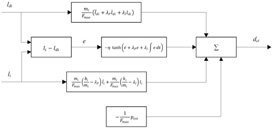
Figure 6.
SMC scheme. The PMW outputs () are calculated with the actuators position feedbacks () and the desired positions () as inputs.
4. Experimental Results
In this section, the performance of the proposed SMC strategy is analysed experimentally. In order to evaluate the SMC strategy, both accuracy and power consumption were compared with the native PI control. For each analysis, graphs and average data were used to analyse the system behaviour. NI MyRIO hardware system and NI LabVIEW 2017 software (National Instruments, Austin, TX, USA) were used to control the Acrome Stewart platform (Acrome, Istanbul, Turkey). Six linear DC actuators drove the platform and provided length feedbacks analogically. The MyRIO PWM output was applied as a voltage to the DC motor via dual H-bridge motor drivers, which actuated as current amplifiers.
The monitoring and control loops were executed in the Xilinx Z-7010 RT processor at 1 kHz. The PWM output, actuator lengths and setpoint data were registered at 50 Hz. The SMC gains were adjusted experimentally: several trials were carried out to tune the control gains adequately and obtain the optimal response of the controller. Low gain values produced high error and a slow system response. On the other hand, it was observed that using control gains that were too high led to chattering and an unstable system response. The PI original gains and the SMC-adjusted gains are displayed in Table 1.

Table 1.
Control gains.
In order to perform the surface inspection, the platform must follow the fixed sweep path schematically marked in black in Figure 2b, which corresponds to the trajectory shown in Figure 7a. In this study, the first two sweeps were analysed to limit the amount of data. The trajectory firstly requires a displacement along the x axis at constant speed, and then, a second displacement in the opposite x direction at a different z level. As mentioned in Section 2, the positioning must be accurate, and particularly, so must the distance between the surface and the camera lens (z axis). Variations lower than +/−1 mm were required to obtain valid inspection images. By using the inverse kinematics, the required leg length setpoint profile was calculated from the inspection trajectory, which is shown in Figure 7b. Because the platform moved along the y axis, each pair of legs moved with the same profile with the following combinations: l1–l6, l2–l5 and l3–l4.
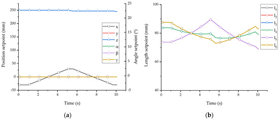
Figure 7.
Trajectories graphs: (a) Stewart platform absolute position and orientation (b) Actuator lengths.
To evaluate the positioning accuracy of each control strategy, both the trajectory error and length error were analysed. The absolute position and angles measurements were not available, therefore the forward kinetic transformation was used to calculate these data from the known actuator lengths. Figure 8a,b shows the length errors in PI and SMC strategies. The PI control produced a smooth actuator response which caused length deviations up to +/− 2.0 mm, as can be observed in Figure 8a. In this figure we can observe that the error in each pair of EMAs l1–l6, l2–l5 and l3–l4 is similar. The SMC provided a better performance and reduced the maximum actuator length error to less than +/− 0.5 mm, as depicted in Figure 8b.
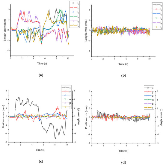
Figure 8.
Positioning error graphs: (a) proportional integral (PI) length errors; (b) SMC length errors graph; (c) PI trajectory errors graph; (d) SMC trajectory errors graph.
PI compared with the SMC shows a similar response during the first 0.5 s, when a continuous setpoint is required. Under those conditions, the integral gain in both control strategies reduced the error successfully. PI command was stable due to the low proportional gain, whereas SMC corrected the actuator positions continuously. Nevertheless, the accumulated error in both strategies was practically the same during this fixed period of time, as shown in Figure 9. Afterwards, as the setpoint commands changed and EMA lengths variations were required, SMC effectively controlled the EMA lengths within an error of less than 0.5 mm, proving the great response of this control strategy. On the contrary, using the PI EMAs errors increased up to 2 mm: the PI control does not provide a proper PWM command to achieve the EMAs setpoints. The PI control showed a slight difference between the upper error (+2 mm) and lower error (−1.5 mm). This deviation was caused by the platform weight, which helps to shorten the EMAs downwards, but impedes their extension upwards.
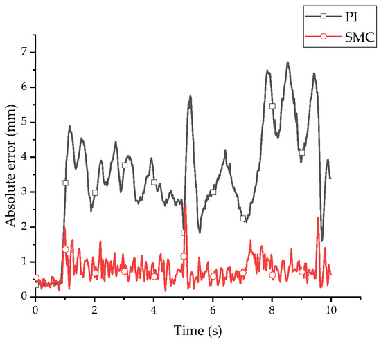
Figure 9.
Absolute error comparison between the two control schemes graph.
The errors in the EMAs mentioned above caused deviations in the positioning of the Stewart platform. Figure 8c,d shows that both control strategies followed the desired trajectory. However, only SMC achieved a positioning y error of between +/− 1 mm. Additionally, the positioning error along the x and z axes was considerably higher when using the PI control. Hence, the PI control, which is not accurate enough, caused most of the recorded images to be defocused. In both strategies, the x and z axis deviation was remarkably smaller than in the y axis, mainly because the movement was in the y direction in the plane x/y: Because each pair of actuators was symmetrically placed along the plane x/y, the control in the z axis was more precise and deviations were compensated between the pairs of actuators. Although SMC presented deviations higher than 1 mm in the x axis, the NDI exhibited a sharp image quality.
Another approach to evaluate the system accuracy is to compare the accumulated absolute EMA error, which is the sum of the absolute error of each actuator. Figure 8 represents the absolute error comparison between PI and SMC. Whereas the PI average error is 3.45 mm, the SMC average error is 0.78 mm. Only when no dynamic response of the EMAs was required, were the PI and SMC absolute errors practically the same. Hence, it may be concluded that the accuracy provided by the SMC strategy is remarkably higher.
To analyse the power consumption, its value was estimated from the duty cycle commands. Once the duty cycle and the actuator maximum consumption were known, the power of each actuator was calculated. Figure 10 shows that the PI control required a smooth power variation. The SMC, as a nonlinear control, required a more demanding peak–valley consumption. In any case, the average power consumption for both control strategies were quite similar: PI = 9.41 watts and SMC = 9.62 watts.
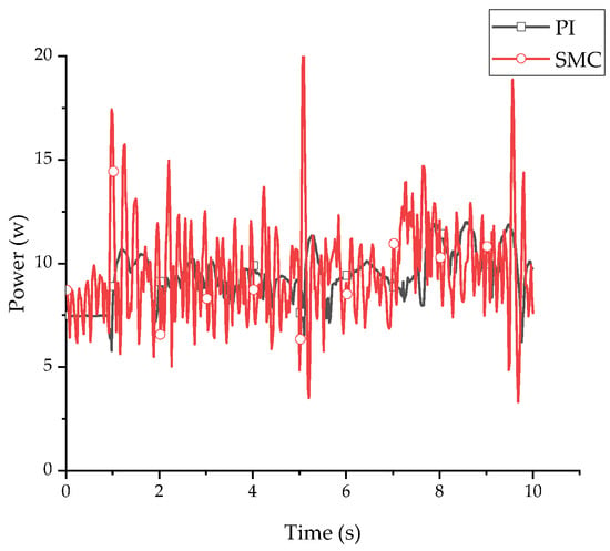
Figure 10.
Power consumption comparison between the two control schemes graph.
5. Conclusions
The use of Stewart platforms as NDI orientation apparatus offers six degrees of freedom, high rigidity, a high payload-to-weight-ratio, and low moving inertia. The aeronautical inspection application presented in this paper requires highly precise positioning, otherwise, non-desirable blurred imaging is obtained affecting the quality of the inspection system. A new control strategy approach, based on the system model analysis, was proposed and validated experimentally as a solution to overcome positioning errors.
The Stewart platform is driven by six electro mechanic actuators that must be coordinated to achieve the desired trajectory and position. The calculation of the kinematics of the mechanism is necessary to obtain the relationship between the position/orientation of the platform and the EMA lengths. Whereas the inverse kinematics can be calculated directly analytically, the forward kinematics require the use of the Newton–Raphson method to find a solution. As an alternative to the native proportional integral (PI) control, which was unable to position the platform accurately enough, a sliding mode control (SMC) system was proposed. The SMC strategy was calculated based on the actuator second-order model with a single element. Interactions between actuators and external disturbances were modelled as perturbations.
The validation, which was performed in the physical technology demonstrator, shows that SMC can be a successful solution to control Stewart platform devices. In comparison with the vendor-provided PI control strategy, the SMC achieves higher performance while executing the actuators commands and desired platform positioning: the average absolute error is reduced from 3.45 mm in PI to 0.78 mm when using the SMC approach presented here. In this range of error, the NDI system succeeds in obtaining sharp images. Although the PI control demands a smoother actuator response, the experimental results prove that the power consumption is similar in both control approaches.
The proposed device was constructed to perform analyses of small plain coupons; however this control scheme can be implemented in bigger parallel platforms and anthropomorphic robotic arms aimed at structure diagnoses of bigger and more complex structures, e.g., aircraft components, car parts, etc. Future research on the topic should be focused on the comparison of SMC with other robust control schemes, such as fuzzy logic controllers, H-infinite and artificial neural networks, and on the development of a hybrid SMC, e.g., fuzzy logic SMC and artificial neural network SMC, to verify whether there is room for improvement.
Author Contributions
Conceptualization, O.B. and C.N.; investigation, J.V. and C.N.; software, J.V. and P.V.; validation, J.V. and P.V.; supervision, I.C. and O.B.; writing—original draft, J.V.; writing—review and editing, J.V., I.C. All authors have read and agreed to the published version of the manuscript.
Funding
This research was funded by the Basque Government through the project SMAR3NAK (ELKARTEK KK-2019/00051), by the Ministerio de Economía y Competitividad (RTI2018-094669-B-C31) and by Aernnova and the Diputación Foral de Álava (DFA) through the project CONAVAUTIN 2 (Collaboration Agreement).
Acknowledgments
The authors wish to express their gratitude to AERNNOVA, the DFA, the Basque Government and UPV/EHU for supporting this work.
Conflicts of Interest
The authors declare no conflict of interest.
References
- Matar, G. Hexapod initiative—Configurable manufacturing. Comput. Ind. 1999, 39, 71–78. [Google Scholar] [CrossRef]
- Olma, S.; Kohlstedt, A.; Traphöner, P.; Jäker, K.P.; Trächtler, A. Observer-based nonlinear control strategies for Hardware-in-the-Loop simulations of multiaxial suspension test rigs. Mechatronics 2018, 50, 212–224. [Google Scholar] [CrossRef]
- Zhang, T.; Zhang, A. Robust finite-time tracking control for robotic manipulators with time delay estimation. Mathematics 2020, 8, 165. [Google Scholar] [CrossRef]
- Kizir, S.; Bingul, Z. Position Control and Trajectory Tracking of the Stewart Platform. Ser. Parallel Robot Manip. Kinemat. Dyn. Control Optim. 2012, 1965. [Google Scholar] [CrossRef]
- Kumar, P.R.; Chalanga, A.; Bandyopadhyay, B. Smooth integral sliding mode controller for the position control of Stewart platform. ISA Trans. 2015, 58, 543–551. [Google Scholar] [CrossRef]
- Karimi, D.; Nategh, M.J. Kinematic nonlinearity analysis in hexapod machine tools: Symmetry and regional accuracy of workspace. Mech. Mach. Theory 2014, 71, 115–125. [Google Scholar] [CrossRef]
- Nguyen, C.; Antrazi, S.; Zhou, Z.L. Analysis and design of a six-degree-of-freedom Stewart platform-based robotic wrist. Comput. Electr. Eng. 1991, 17, 191–203. [Google Scholar] [CrossRef]
- Huang, Y.; Pool, D.M.; Stroosma, O.; Chu, Q.P. Incremental Nonlinear Dynamic Inversion Control for Hydraulic Hexapod Flight Simulator Motion Systems. IFAC-PapersOnLine 2017, 50, 4294–4299. [Google Scholar] [CrossRef]
- Lin, H.; McInroy, J.E. Disturbance attenuation in precise hexapod pointing using positive force feedback. Control Eng. Pract. 2006, 14, 1377–1386. [Google Scholar] [CrossRef]
- Keshtkar, S.; Keshtkar, J.; Poznyak, A. Adaptive sliding mode control for solar tracker orientation. Proc. Am. Control Conf. 2016, 2016, 6543–6548. [Google Scholar] [CrossRef]
- Davliakos, I.; Papadopoulos, E. Model-based control of a 6-dof electrohydraulic Stewart-Gough platform. Mech. Mach. Theory 2008, 43, 1385–1400. [Google Scholar] [CrossRef]
- Ting, Y.; Li, C.C.; Jar, H.C.; Kang, Y. Task-space measurement and control for a 6DOF Stewart nanoscale platform. In Proceedings of the 2007 IEEE International Conference on Mechatronics and Automation ICMA 2007, Harbin, China, 5–8 August 2007; pp. 174–179. [Google Scholar] [CrossRef]
- Fraguela, L.; Fridman, L.; Alexandrov, V.V. Output integral sliding mode control to stabilize position of a Stewart platform. J. Frankl. Inst. 2012, 349, 1526–1542. [Google Scholar] [CrossRef]
- Chen, W.; Xu, T.; Liu, J.; Wang, M.; Zhao, D. Picking Robot Visual Servo Control Based on Modified Fuzzy Neural Network Sliding Mode Algorithms. Electronics 2019, 8, 605. [Google Scholar] [CrossRef]
- Usamentiaga, R.; Venegas, P.; Guerediaga, J.; Vega, L.; Molleda, J.; Bulnes, F.G. Infrared thermography for temperature measurement and non-destructive testing. Sensors 2014, 14, 12305–12348. [Google Scholar] [CrossRef] [PubMed]
- Harib, K.; Srinivasan, K. Kinematic and dynamic analysis of Stewart platform-based machine tool structures. Robotica 2003, 21, 541–554. [Google Scholar] [CrossRef]
- Dhingra, A.K.; Almadi, A.N.; Kohli, D. A gröbner-sylvester hybrid method for closed-form displacement analysis of mechanisms. J. Mech. Des. Trans. 2000, 122, 431–438. [Google Scholar] [CrossRef]
- Umar, A.; Shi, Z.; Khlil, A.; Farouk, Z.I.B. Developing a new robust swarm-based algorithm for robot analysis. Mathematics 2020, 8, 158. [Google Scholar] [CrossRef]
- Xi, F.; Sinatra, R. Inverse dynamics of hexapods using the natural orthogonal complement method. J. Manuf. Syst. 2002, 21, 73–82. [Google Scholar] [CrossRef]
- Chen, J.; Lan, F. Instantaneous stiffness analysis and simulation for hexapod machines. Simul. Model. Pract. Theory 2008, 16, 419–428. [Google Scholar] [CrossRef]
- Akdaǧ, M.; Karagülle, H.; Malgaca, L. An integrated approach for simulation of mechatronic systems applied to a hexapod robot. Math. Comput. Simul. 2012, 82, 818–835. [Google Scholar] [CrossRef]
- Omran, A.; El-Bayiumi, G.; Bayoumi, M.; Kassem, A. Genetic algorithm based optimal control for a 6-dof non redundant stewart manipulator. Int. J. 2008, 2, 73–79. [Google Scholar]
- Velasco, J.; Barambones, O.; Calvo, I.; Zubia, J.; de Ocariz, I.S.; Chouza, A.; Saez de Ocariz, I.; Chouza, A. Sliding Mode Control with Dynamical Correction for Time-Delay Piezoelectric Actuator Systems. Materials 2019, 13, 132. [Google Scholar] [CrossRef] [PubMed]
- Le Nhu Ngoc Thanh, H.; Vu, M.T.; Mung, N.X.; Nguyen, N.P.; Phuong, N.T. Perturbation observer-based robust control using a multiple sliding surfaces for nonlinear systems with influences of matched and unmatched uncertainties. Mathematics 2020, 8, 1371. [Google Scholar] [CrossRef]
- Florez, F.; de Córdoba, P.F.; Higón, J.L.; Olivar, G.; Taborda, J. Modeling, simulation, and temperature control of a thermal zone with sliding modes strategy. Mathematics 2019, 7, 503. [Google Scholar] [CrossRef]
- Kim, N.I.; Lee, C.W. High speed tracking control of Stewart platform manipulator via enhanced sliding mode control. In Proceedings of the 1998 IEEE International Conference on Robotics and Automation (Cat. No.98CH36146), Leuven, Belgium, 16–20 May 1998; Volume 3, pp. 2716–2721. [Google Scholar]
- Kumar, P.R.; Chalanga, A.; Bandyopadhyay, B. Position control of Stewart platform using continuous higher order sliding mode control. In Proceedings of the 2015 10th Asian Control Conference (ASCC), Kota Kinabalu, Malaysia, 31 May–3 June 2015; pp. 1–6. [Google Scholar] [CrossRef]
- Flottmeier, S.; Olma, S.; Trächtler, A. Sliding mode and continuous estimation techniques for the realization of advanced control strategies for parallel kinematics. IFAC Proc. Vol. 2014, 19, 182–190. [Google Scholar] [CrossRef]
- Bo, W.; Yanlang, D.; Shenglin, W.; Dongguang, X.; Keding, Z. An integral variable structure controller with fuzzy tuning design for electro-hydraulic driving Stewart Platform. In Proceedings of the 2006 1st International Symposium on Systems and Control in Aerospace and Astronautics, Harbin, China, 19–21 January 2006; pp. 941–945. [Google Scholar] [CrossRef]
- Li, Y.; Xu, Q. Adaptive Sliding Mode Control With Perturbation Estimation and PID Sliding Surface for Motion Tracking of a Piezo-Driven Micromanipulator. IEEE Trans. Control Syst. Technol. 2010, 18, 798–810. [Google Scholar] [CrossRef]
Publisher’s Note: MDPI stays neutral with regard to jurisdictional claims in published maps and institutional affiliations. |
© 2020 by the authors. Licensee MDPI, Basel, Switzerland. This article is an open access article distributed under the terms and conditions of the Creative Commons Attribution (CC BY) license (http://creativecommons.org/licenses/by/4.0/).