Abstract
Underground gas hydrate storage of natural gas is a rather promising way of creating underground storage facilities for hydrocarbon raw materials in porous reservoirs. This paper presents a solution to the problem of the formation of CH4 hydrate in a porous medium during the injection of methane into a reservoir at a temperature lower than the initial temperature of the reservoir. Self-similar solutions of the problem in axisymmetric approximation are given, describing the pressure and temperature distribution in separate reservoir regions at the formation of gas hydrate on the frontal surface. On the basis of the method of sequential change of stationary states, an analytical solution was obtained, which allowed us to determine the position of the methane hydrate formation boundary depending on different parameters for any moment of time. The limits of the applicability of the proposed model are also given. Thus, the analysis of the calculation results showed that the constructed solution allows one to sufficiently and accurately determine the values of parameters at the frontal surface for a highly permeable medium (k0 > 10−13 m2). It was proved that in the case of a highly permeable medium, the methane hydrate formation intensity will be limited by convective heat dissipation during hydrate formation.
1. Introduction
Natural gas (primarily methane) is currently considered to be one of the most widely used fossil fuels [1,2]. An important issue when using this hydrocarbon raw material is the improvement in the technology of storing natural gas. In other words, there is a need to establish gas storage facilities in conditions that contribute to the effective preservation of gas reserves over a certain time period [2]. At present, underground hydrocarbon gas storage facilities created in porous reservoirs are quite widespread (as a rule, these are depleted oil and/or natural gas deposits). In order to increase the capacity of such underground reservoirs, it is possible to convert gas in porous reservoirs from a free state to a gas-hydrate one.
Gas hydrates are non-stoichiometric solid compounds similar to ice crystals [3,4,5]. In these compounds, water molecules form clathrate-like structures in which gases with low molecular weight act as guest molecules [3,6]. Since there is no chemical bond between water and gas molecules, gas extraction is possible by reducing the pressure and/or thermal effect on the deposit [7,8]. A number of papers (for example, [9,10,11,12,13,14,15]) have presented theoretical approaches to solving these problems. That is, there is a great deal of attention given to the application of mathematical methods in solving practical problems [16,17,18].
In [19], the authors in a plane-parallel formulation investigated the features of gas hydrate formation in a porous medium when cold gas (with a temperature lower than the initial reservoir temperature) is injected into a semi-infinite porous reservoir saturated in the initial state with methane and water. Self-similar solutions of this problem are constructed in straight-parallel approximation, describing the distribution of the main parameters in the reservoir of gas hydrate both on the frontal surface and in the extended region. A similar problem was considered in [20]. In particular, it is shown that there are three possible filtration modes in a porous medium, which differ qualitatively in the fields of temperature and hydrate saturation, namely: filtration without the formation of a gas hydrate in the porous medium; frontal mode of phase transitions; and the bulk mode of hydrate formation. In [21], the process of gas hydrate formation was considered in a porous reservoir of finite length. The numerical implementation of the mathematical model of the process under study presented in the work was carried out using the method of catching the front into a grid node. In [22], a similar initial and boundary value problem was solved by the finite difference method using the iterative algorithm and the sweep method. However, in contrast to papers [19,20,21], a mathematical model was used, which took into account a greater number of the main physical features of the process under study: the real properties of the gas, the Joule-Thomson effect, and the joint movement of water and gas.
In our previous article [23], an approximate solution to the problem of the gas hydrate formation in a porous medium was constructed in the form of an explicit functional dependence of the self-similar coordinate of the hydrate formation boundary on the parameters of the porous medium and injected gas. In papers [13,14,15,19,20], for similar problems, self-similar solutions were obtained that described the distributions of pressure and temperature in a reservoir. However, when these solutions are substituted into the relations on the moving boundaries of phase transitions, a system of transcendental equations arises (resulting from the conditions of mass and energy balance), which in the general case can be solved only by numerical methods. This greatly complicates the mathematical model analysis. In this paper, in contrast to [13,14,15,16,17,18], for the plane-radial case, an analytical solution is obtained that allows for each time point to find the coordinate of the methane hydrate formation boundary depending on various parameters: mass flow rate and temperature of the gas injected into a reservoir, parameters of the porous medium skeleton, porosity, and the initial reservoir water saturation. The obtained solution allows for the analysis of the basic properties of a hydrate-containing system to determine the possible structures of the mathematical solution of the problem, and also identify the conditions and mechanisms that determine the possibility of implementing a particular mode of gas hydrate formation in a natural reservoir.
This article is structured as follows. The problem statement, the basic equations, and the self-similar solution of the problem are given, the system of equations is written to find the coordinates of the hydrate formation boundary, and the values of the parameters on it. The numerical solution of the above system of transcendental equations shows that at sufficiently high permeability values of the porous medium, the temperature in a small section of the formation near the surface of methane hydrate formation rises sharply (i.e., we can talk about a temperature jump [23]). For the case of a temperature jump at the front of the gas hydrate formation using the method of sequential changes of stationary states, an approximate analytical solution was constructed that allowed for any moment of time to determine the position of the boundary of methane hydrate formation depending on various parameters. Then, the results of comparing the numerical and constructed analytical solutions are presented, which show the limits of applicability of the proposed model.
2. Mathematical Modeling of the Process of Gas Hydrate Formation in a Porous Medium
Figure 1 shows the scheme of the considered model problem of gas injection into a horizontal porous layer of infinite length, constant thickness, and with an impermeable roof and bottom. The porous collector is initially filled with methane and water. Injection of gas (methane) with a constant temperature Tw, lower than the initial reservoir temperature T0, occurs through a perfect well (opening the porous layer for its entire thickness) at a constant mass (per unit height of the well) flow rate Q:
where p is the pressure; T is the temperature; ρg and vg are the density and gas phase velocity; m is the reservoir porosity; Sj (j = g, l, h) is the pore saturation with j-th phase; and Sl0 is the initial reservoir water saturation. Subscripts sk, h, l, and g refer to the parameters of the porous skeleton, gas hydrate, water, and gas.
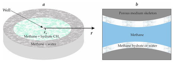
Figure 1.
(a) is the schematic representation of the studied process, (b) is the schematic representation of the considered porous medium.
When gas is injected, its particles will move along horizontal trajectories radially emanating from the well. The pattern of current lines, in this case, in any horizontal plane is the same, and for the full flow characteristic, it suffices to study the motion in any horizontal plane [24,25]. In such a flow, all parameters characterizing filtration at any point depend only on the distance r of a given point from the well axis (i.e., the flow will be plane-radial (axisymmetric)).
This paper considered the frontal regime of methane hydrate formation (Figure 1a). For this regime, there are two zones in the formation saturated respectively with methane and its hydrate (near or first zone) as well as gas and water (far or second zone). It was assumed that hydrate is located on the walls of the pore channel (Figure 1b), so the hydrate saturation Sh, is the fraction of the pore volume occupied by hydrate, with the rest of the pore volume, equal to 1–Sh, saturated with mobile gas. The same assumption was applied to water.
Assume that m, ρsk, ρh, ρl = const, υsk, υh, υl = 0, where ρj and vj (j = g, l, h) are the density and velocity of the j-th phase [26]. Assuming also that gas is only in the gaseous and hydrated states, and water is only in the liquid or hydrated states (i.e., ice and vapor formation processes are absent), then for gas, we took the Clapeyron–Mendeleev equation as the equation of state.
In the considered problem, the velocity of the front of the phase transitions will be limited by the rate of heat dissipation during the formation of a hydrate (i.e., heat transfer in a reservoir [27]). This was due to the fact that heat transfer in extended natural reservoirs proceeds very slowly, therefore the condition of phase equilibrium on the surface of phase transitions is met:
where ps0 is the equilibrium pressure corresponding to the initial temperature T0; T* is an empirical parameter that has the dimension of temperature and depends on the natural gas composition; and subscript s in brackets refers to the parameters at the border of hydrate formation.
For the stated problem statement in [26,27], a system of nonlinear differential equations describing the filtration flow of gas, taking into account the process of hydrate formation, was proposed on the basis of the methods and approaches of the mechanics of multiphase media [28] for the plane-radial case. Appendix A contains this system of basic equations, the self-similar solution of the problem, and a system of transcendental equations to find the coordinate of the hydrate formation and the values of parameters on it.
From the system of transcendental Equation (A7), taking into account Equation (2), by using a numerical method, we can find the value of the self-similar coordinate of the gas hydrate formation front ξ(s), and then the value of the physical coordinate of this front:
The solution of the above system of transcendental equations, and accordingly, finding the coordinates of the gas hydrate formation front ξ(s) is possible only with the use of numerical methods. However, in order to analyze the mathematical model of the process under study, it is of more interest to obtain a solution in the form of a function of the coordinate of the hydrate formation boundary r(s), from the parameters of the injected gas and porous medium. To construct such a solution, we used the type of temperature distribution curve at sufficiently high permeabilities of a porous medium k0.
Figure 2 shows the temperature distribution in a reservoir at 10 h after the start of methane injection. The original parameters used in the model are shown in Table 1 [3,19,26,29,30,31]:
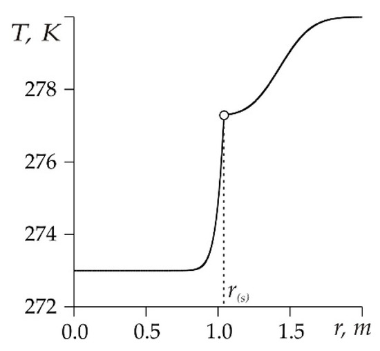
Figure 2.
The change in temperature on coordinate r.

Table 1.
Basic parameters for the model.
Figure 2 shows that the temperature in a small section of the reservoir near the surface of the CH4 hydrate formation sharply rose from Tw to T(s) (i.e., we can talk about a temperature jump [23]). In this case, to obtain an approximate analytical solution, it is possible to simplify the conditions at the phase transition boundary by adopting a stepwise change in the temperature by coordinate r.
3. Construction of an Approximate Analytical Solution
For the case of a temperature jump at the gas hydrate formation front, the temperature field in the vicinity of the phase transition boundary r(s) is determined by two temperatures: Tw and T(s) (Figure 3). The step-by-step nature of the temperature distribution in the reservoir is determined by the following factors: the given temperature of the gas pumped into the reservoir; heat release during the formation of gas hydrate; and the determining role of the convective mechanism of heat transfer in a porous medium in the considered case.
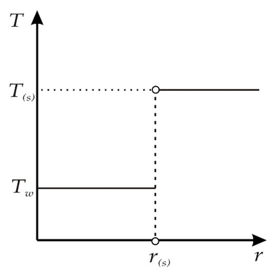
Figure 3.
Schematic temperature distribution in a reservoir.
Taking into account the accepted temperature distribution (Figure 3), we detail the conditions for the balance of mass and heat for r = r(s):
where is the speed of movement of the phase transition boundary. When writing the mass balance equation, the term responsible for gas absorption was neglected due to its small influence (due to continuous gas injection into a reservoir) on the pressure change in a reservoir.
Taking into account that (i = 1, 2) and , the last equation will take the form:
where i = 1 and 2 corresponds to the parameters of the first and second zones.
Multiplying Equation (3) by T(s) and adding up with Equation (4), we obtain:
The following expression can be written from the last equation for the velocity of movement of the gas hydrate formation boundary:
As seen from Equation (5), to find the velocity of the gas hydrate formation boundary, , we need to know how the reservoir pressure changes. To find the pressure distribution p(r, t), we used the method of successive change of stationary states [24]. We will assume that for each time moment, there is a perturbed region of finite radius R(t), in which the stationary filtration of the gas takes place:
where pw is the bottom hole pressure and p0 is the initial (undisturbed) pressure.
Outside the perturbed region, the pressure is equal to the initial: .
Let us express the pressure value through the mass flow rate Q. In the case of the steady-state flat radial filtration, the expression for Q has the form [24]:
Hence:
Substituting the last expression into Equation (6), we get:
Thus, we obtained the pressure distribution expressed in terms of a given mass flow rate and the reservoir parameters. To find the radius of the perturbed region R(t), we make use of the mass-balance equation.
The initial gas reserve (at p = p0) in the reservoir zone of radius R(t) is equal to:
where H is the reservoir thickness.
The current gas reserve is expressed through the weighted average pressure :
where the weighted average pressure is determined by the equation of the flat-radial steady-state filtration of a perfect gas:
In the considered problem, gas injection occurs with a constant mass flow rate Q, therefore the gas mass pumped into a reservoir at time t is equal to QHt. At the same time, the rate of increase in the length of the perturbed region R(t) considerably exceeds the speed of movement of the gas hydrate formation boundary. In this case, neglecting the absorption of gas at the phase transition boundary, we have:
Substituting Equations (9)–(11) into this equation, and taking into account Equation (7), we obtain:
For time values for which , we have:
Now, knowing the law of motion of the boundary of the perturbed region, from Equation (8) we can find the pressure at each reservoir point at any time:
From this relation we have:
Substituting Equation (13) into Equation (5), we can write the following equation:
Integrating this equation, we get:
To find the coordinate of the gas hydrate formation boundary from Equation (14), it is necessary to know the values of pressure and temperature at this boundary. Figure 4 shows the dependences on the permeability of the values of temperature and pressure at the gas hydrate formation boundary obtained by numerically solving the system of Equation (A7).
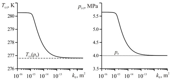
Figure 4.
The change in temperature and pressure at the phase transition boundary depending on the permeability. Sl0 = 0.1, T0 = 278 K, Q = 0.01 kg/(m∙s); other parameters correspond to Figure 2.
From Figure 4, it can be seen that as the permeability k0 decreases, the pressure p(s) at the phase transition boundary and the temperature T(s) connected with it by relation (2) increases. This increase in p(s) with a decrease in k0 can be explained by the need to increase the well bottom pressure pw, because in the problem it was assumed that the mass flow rate of gas injection Q is constant (Darcy’s law) [23]. Accordingly, the pressure in the near well area increases. Moreover, for the values of temperature and pressure at the phase transition boundary, there are maximum values. The temperature increase is due to the release of the latent heat of gas hydrate formation and the maximum temperature at the gas hydrate formation boundary is:
Figure 4 shows that for a highly permeable medium (k0 > 10−13 m2), the pressure on the phase transition surface asymptotically approaches p0, and the temperature on this surface approaches the equilibrium phase transition temperature T(s)(p0), determined from Equation (2) for the pressure p0. Thus, at sufficiently high permeability values (k0), the following conditions are met:
Substituting Equation (15) into Equation (14), we obtain the following solution for the coordinate of the hydrate formation boundary:
Obtained solution (16) allows for any time point to determine the position of the methane hydrate formation boundary depending on various parameters.
4. Calculations Results Using Obtained Analytical Solution
Let us determine the applicability limits of the proposed mathematical model taking into account a stepwise temperature distribution on coordinate z. For this purpose, we compared the results of calculating the phase transition boundary coordinate according to Equation (16) with the solution of the system of transcendental Equation (A7), taking into account Equation (2). This solution can only be obtained using some numerical method (further referred to as “numerical solution”).
Figure 5 shows the change in the coordinate of the phase transition boundary depending on permeability, mass flow rate (in 10 h after the start of gas injection), and time. The solid curve corresponds to the numerical solution; the dashed curve corresponds to solution (16). The solution with a temperature jump on the surface of methane hydrate formation (16) only takes into account the convective heat transfer mechanism.
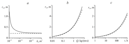
Figure 5.
Change of the coordinate of the phase transition boundary depending on the permeability (a), mass flow rate (b), and time (c); a and c − Q = 0.01 kg/(m∙s), b and c − k0 = 10−12 m2; other parameters correspond to Figure 2.
From the data presented in Figure 5c, it can be seen that over time, the hydrate formation boundary r(s) moves deep into the reservoir. Additionally, with the increase in the mass flow rate Q of the injected gas into the formation, the value of r(s) increases (Figure 5b). This is due to the following factors. For the formation of gas hydrate, the value of the reservoir temperature should not exceed the equilibrium temperature T(s) (associated with pressure through relation (2)). However, the initial reservoir temperature T0 in this case is higher than the temperature T(s). In addition, the process of hydrate formation is accompanied by an increase in temperature due to the release of latent heat of phase transitions. In this regard, to start and maintain the process of hydrate formation an increase in temperature T(s) (through an increase in pressure) and the removal of heat released during phase transitions are necessary. With increasing Q, the reservoir pressure increases, which means that the equilibrium hydrate formation temperature T(s) associated with it through Equation (2) increases. Additionally, with increasing Q, the intensity of convective heat transfer in a reservoir increases and, accordingly, the rate of heat removal, released at the phase transition boundary, increases. Therefore, large values of the mass flow rate Q correspond to large values of the coordinate of the gas hydrate formation boundary r(s).
Figure 5a shows that for sufficiently large permeabilities (k0 > 10−13 m2), the numerical solution and solution (16) practically coincide. So, in the case of a highly permeable medium, the rate of hydrate formation in a natural reservoir will be limited by convective heat removal generated during the formation of CH4 hydrate.
Numerical solution of the system of Equation (A7) shows that as the permeability k0 decreases, the phase transitions boundary r(s) moves farther and farther away from the well (Figure 5a). Such an increase in r(s) with decreasing k0 and a constant mass flow rate Q is explained by the need to increase the injection pressure, which in turn, leads to an increase in the pressure at the phase transition boundary. Additionally, it accelerates the process of the formation of gas hydrate because it increases the equilibrium temperature of hydrate formation T(s) connected with pressure through Equation (2).
The decrease in k0 does not affect the values of r(s) (Figure 5a) found from the approximate analytical solution (16), which is due to the use of assumption (15) on the constancy of pressure at the phase transition boundary as well as the constancy of the gas injection mass flow rate Q. Figure 5 shows that the constructed solution (16) well describes the movement of the gas hydrate formation boundary for highly permeable media (k0 > 10−13 m2). It is also worth noting that as the permeability k0 decreases, the value of r(s) found from solution (16) is increasingly different (becomes less) from the value of the hydrate formation boundary coordinate found from the numerical solution. This difference in the calculation results can be explained by the fact that, according to Figure 4, with a decrease in permeability, the pressure at the gas hydrate formation boundary increases and therefore the use of condition (15) introduces significant errors in the calculation of the value of r(s), according to the approximate analytical solution (16).
From Equation (12), the pressure values at the phase transition boundary take the form:
On the basis of Equation (17) and using Equations (2) and (16), we can write approximate analytical solutions for the pressure and temperature at the phase transition boundary in the form of their explicitly defined functional dependence on the parameters of injected gas and porous medium:
Figure 6 shows the calculations of temperature and pressure at the gas hydrate formation boundary made on the basis of a numerical solution of the system of Equations (A7) (solid curve) and analytical solution (18) (dashed curve). The time of the injection of methane into a reservoir was 10 h; other parameters correspond to Figure 5.
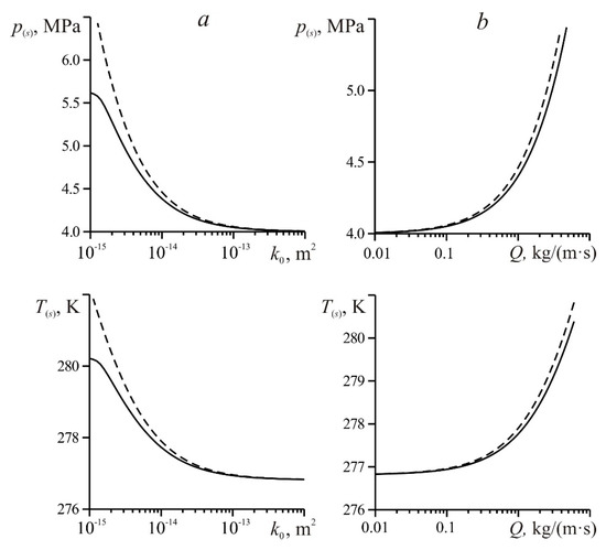
Figure 6.
Changes in pressure and temperature at the phase transition boundary depending on the permeability (a) and mass flow rate (b).
From the data presented in Figure 6, it can be seen that for highly permeable media (k0 > 10−13 m2) the constructed solution (18) allows one to accurately determine the values of pressure and temperature at the phase transition boundary. Figure 6 shows that with a decrease in permeability k0 and an increase in the gas injection mass flow Q, the values of pressure p(s) and temperature T(s), calculated from the approximate analytical solution (18), increasingly differ (become larger) from the values p(s) and T(s) found from the numerical solution. This is due to the fact that, according to Figure 5, with a decrease in permeability and an increase in mass flow rate, the position of the surface formation of methane hydrate, found from solution (16), is increasingly different from the values of r(s) found from the numerical solution. According to Equation (17), as the coordinate r(s) decreases (that is, as it approaches the well), the pressure and, accordingly, the equilibrium temperature of gas hydrate formation increases.
5. Conclusions
A mathematical model is presented that describes the flow in a natural reservoir, taking into account the gas hydrate formation. Based on the method of the successive change of stationary states, an approximate analytical solution was obtained with a temperature jump at the phase transitions front. This solution allows for any time point to determine the position of the methane hydrate formation boundary depending on various parameters. It was shown that this solution allows one to accurately determine the values of pressure, temperature, and coordinate of the phase transition boundary at sufficiently high permeability values (k0 > 10−13 m2). At sufficiently small values of reservoir permeability k0 and sufficiently large values of the injected gas mass flow rate Q, the coordinate r(s) of the methane hydrate formation surface, calculated using the constructed analytical solution, has underestimated values compared to the coordinate r(s), found from the solution with continuous temperature distribution at the boundary of phase transitions; moreover, with a decrease in k0 and an increase in Q, this difference grows. Additionally, with a decrease in k0 and an increase in Q, the values of pressure and temperature at the phase transition boundary, calculated from an approximate analytical solution, become increasingly higher when compared to their values found on the basis of the numerical solution.
Author Contributions
The concept, main editing, and supervision of the article was given by N.G.M. All the computations, writing first draft, and methodology of the proof was done by M.K.K. All authors have read and agreed to the published version of the manuscript.
Funding
The study was funded by the Russian Foundation for Basic Research according to the research project no. 18-29-10023.
Acknowledgments
The authors are grateful to Stanislav L. Borodin for help with translating the article.
Conflicts of Interest
The authors declare no conflict of interest.
Appendix A. The System of Basic Equations, a Self-Similar Solution of the Considered Problem, and System of Transcendental Equations for Finding the Coordinate of the Hydrate Formation Boundary and the Values of Parameters on It
For the presented problem statement for the plane-radial case, a system of nonlinear differential equations describing the gas flow in a porous medium can be represented in the form [26,27]:
where χ(T) is the coefficient of thermal diffusivity (thermal conductivity coefficient) of a reservoir; ρj, cj and λj (j = sk, h, l, g) are the true density, specific heat capacity, and thermal conductivity of the j-th phase; and μg is the dynamic viscosity of gas phase.
The formulated problem has an self-similar solution. We introduced an self-similar variable . Given that:
we obtain the following system of ordinary differential equations:
Integrating Equations (A3) and (A4), for the distribution of pressure and temperature in each of the zones, we can write the following integral relations:
Here, Rg is the specific gas constant and ξ(s) is the self-similar coordinate of the hydrate formation boundary.
As also seen in [26,27], the system of equations was written to find the coordinate of the hydrate formation boundary and the values of parameters on it. This system of equations follows from the conditions of mass-heat balance on the frontal surface of phase transitions. After substituting solutions (A5) and (A6), this system can be presented as follows:
where G is the mass concentration of gas in methane hydrate and Lh is the specific heat of hydrate formation.
References
- Gibilisco, S. Alternative Energy Demystified; McGraw-Hill: New York, USA, 2007; p. 324. [Google Scholar]
- Veluswamy, H.P.; Kumar, A.; Seo, Y.; Lee, J.D.; Linga, P. A review of solidified natural gas (SNG) technology for gas storage via clathrate hydrates. Appl. Energy 2018, 216, 262–285. [Google Scholar] [CrossRef]
- Sloan, E.D.; Koh, C.A. Clathrate Hydrates of Natural Gases; CRC Press: Boca Raton, FL, USA, 2007; p. 752. [Google Scholar]
- Makogon, Y.F. Hydrates of Hydrocarbons; PennWell Publishing Company: Tulsa, OK, USA, 1997; p. 503. [Google Scholar]
- Chernov, A.A.; Elistratov, D.S.; Mezentsev, I.V.; Meleshkin, A.V.; Pil’nik, A.A. Hydrate formation in the cyclic process of refrigerant boiling-condensation in a water volume. Int. J. Heat Mass Transf. 2017, 108, 1320–1323. [Google Scholar] [CrossRef]
- Bohrmann, G.; Torres, M.E. Gas hydrates in marine sediments. In Marine Geochemistry; Springer: Berlin/Heidelberg, Germany, 2006; pp. 481–512. [Google Scholar] [CrossRef]
- Birchwood, R.; Dai, J.; Shelander, D.; Boswell, R.; Collet, T.; Cook, A.; Dallimore, S.; Fujii, K.; Imasato, Y.; Fukuhara, M.; et al. Developments in Gas Hydrates. Oilfield Rev. Spring 2010, 22, 18–33. [Google Scholar]
- Demirbas, A. Methane Gas Hydrate; Springer: London, UK, 2010; pp. 57–76. [Google Scholar]
- Moridis, G.J.; Queiruga, A.F.; Reagan, M.T. Simulation of Gas Production from Multilayered Hydrate-Bearing Media with Fully Coupled Flow, Thermal, Chemical and Geomechanical Processes Using TOUGH + Millstone. Part 1: Numerical Modeling of Hydrates. Transp. Porous Media 2019, 128, 405–430. [Google Scholar] [CrossRef]
- Queiruga, A.F.; Moridis, G.J.; Reagan, M.T. Simulation of Gas Production from Multilayered Hydrate-Bearing Media with Fully Coupled Flow, Thermal, Chemical and Geomechanical Processes Using TOUGH + Millstone. Part 2: Geomechanical Formulation and Numerical Coupling. Transp. Porous Media 2019, 128, 221–241. [Google Scholar] [CrossRef]
- Vasil’ev, V.I.; Popov, V.V.; Tsypkin, G.G. Numerical investigation of the decomposition of gas hydrates coexisting with gas in natural reservoirs. Fluid Dyn. 2006, 41, 599–605. [Google Scholar] [CrossRef]
- Misyura, S.Y.; Donskoy, I.G. Ways to improve the efficiency of carbon dioxide utilization and gas hydrate storage at low temperatures. J. CO2 Utili. 2019, 34, 313–324. [Google Scholar] [CrossRef]
- Shagapov, V.S.; Chiglintseva, A.S.; Rusinov, A.A. Theoretical modeling of gas extraction from a partially gas-saturated porous gas-hydrate reservoir with respect to thermal interactions with surrounding rocks. Theor. Found. Chem. Eng. 2016, 50, 449–458. [Google Scholar] [CrossRef]
- Tsypkin, G.G. Mathematical model for dissociation of gas hydrates coexisting with gas in strata. Dokl. Phys. 2001, 46, 806–809. [Google Scholar] [CrossRef]
- Shagapov, V.S.; Chiglintseva, A.S.; Syrtlanov, V.R. Possibility of gas washout from a gas-hydrate massif by circulation of warm water. J. Appl. Mech. Tech. Phys. 2009, 50, 628–637. [Google Scholar] [CrossRef]
- Li, N.; Mok, I.A.C.; Cao, Y. The Evolution of Mathematical Thinking in Chinese Mathematics Education. Mathematics 2019, 7, 297. [Google Scholar] [CrossRef]
- Badruddin, I.A. Numerical Analysis of Thermal Non-Equilibrium in Porous Medium Subjected to Internal Heating. Mathematics 2019, 7, 1085. [Google Scholar] [CrossRef]
- Marsavina, L.; Nurse, A.D.; Braescu, L.; Craciun, E.M. Stress singularity of symmetric free-edge joints with elasto-plastic behaviour. Comput. Mater. Sci. 2012, 52, 282–286. [Google Scholar] [CrossRef]
- Shagapov, V.S.; Musakaev, N.G.; Khasanov, M.K. Formation of gas hydrates in a porous medium during an injection of cold gas. Int. J. Heat Mass Transf. 2015, 84, 1030–1039. [Google Scholar] [CrossRef]
- Nurislamov, O.R.; Shagapov, V.S. Gas injection into a moist porous medium with the formation of a gas hydrate. J. Appl. Math. Mech. 2009, 73, 581–591. [Google Scholar] [CrossRef]
- Shagapov, V.S.; Khasanov, M.K.; Gimaltdinov, I.K.; Stolpovskii, M.V. Numerical modeling of formation of a gas hydrate in a finite-length porous bed purged by a gas. J. Appl. Mech. Tech. Phys. 2011, 52, 599–607. [Google Scholar] [CrossRef]
- Bondarev, E.A.; Rozhin, I.I.; Popov, V.V.; Argunova, K.K. Underground storage of natural gas in hydrate state: Primary injection stage. J. Eng. Thermophys. 2018, 27, 221–232. [Google Scholar] [CrossRef]
- Musakaev, N.G.; Khasanov, M.K. Analytical solution of the problem of hydrate formation in a porous medium with a temperature jump at the phase transition front. J. Phys. 2019, 1268, 012051. [Google Scholar] [CrossRef]
- Basniev, K.S.; Kochina, I.N.; Maksimov, V.M. Underground Fluid Mechanics; Nedra: Moscow, Russia, 1993; p. 416. (In Russian) [Google Scholar]
- Sun, X.; Nanchary, N.; Mohanty, K.K. 1-D modeling of hydrate depressurization in porous media. Transp. Porous Media 2005, 58, 315–338. [Google Scholar] [CrossRef]
- Shagapov, V.S.; Khasanov, M.K.; Musakaev, N.G. Formation of a gas hydrate due to injection of a cold gas into a porous reservoir partly saturated by water. J. Appl. Mech. Tech. Phys. 2008, 49, 462–472. [Google Scholar] [CrossRef]
- Shagapov, V.S.; Musakaev, N.G. Dynamics of Formation and Decomposition of Hydrates in the Systems of Gas. Production, Transportation and Storage; Nauka: Moscow, Russia, 2016; p. 240. (In Russian) [Google Scholar]
- Nigmatulin, R.I. Dynamics of Multiphase Media; Hemisphere Publ. Corp.: New York, NY, USA, 1991. [Google Scholar]
- Shagapov, V.S.; Khasanov, M.K.; Musakaev, N.G. Injection of liquid carbon dioxide into a reservoir partially saturated with methane hydrate. J. Appl. Mech. Tech. Phys. 2016, 57, 1083–1092. [Google Scholar] [CrossRef]
- Vlasov, V.A. Diffusion model of gas hydrate formation from ice. Heat Mass Transf. 2016, 52, 531–537. [Google Scholar] [CrossRef]
- Musakaev, N.G.; Borodin, S.L.; Khasanov, M.K. The mathematical model of the gas hydrate deposit development in permafrost. Int. J. Heat Mass Transf. 2018, 118, 455–461. [Google Scholar] [CrossRef]
© 2020 by the authors. Licensee MDPI, Basel, Switzerland. This article is an open access article distributed under the terms and conditions of the Creative Commons Attribution (CC BY) license (http://creativecommons.org/licenses/by/4.0/).