Article

A Nonlinear Systems Framework for Cyberattack Prevention for Chemical Process Control Systems

Department of Chemical Engineering and Materials Science, Wayne State University, Detroit, MI 48202, USA
This paper is an extended version of our paper published in the Proceedings of the 6th IFAC Conference on Nonlinear Model Predictive Control.
Current address: 5050 Anthony Wayne Drive, Detroit, MI 48202, USA.
Mathematics 2018, 6(9), 169; https://doi.org/10.3390/math6090169
Submission received: 13 August 2018 / Revised: 11 September 2018 / Accepted: 12 September 2018 / Published: 14 September 2018
(This article belongs to the Special Issue New Directions on Model Predictive Control)

Abstract

:
Recent cyberattacks against industrial control systems highlight the criticality of preventing future attacks from disrupting plants economically or, more critically, from impacting plant safety. This work develops a nonlinear systems framework for understanding cyberattack-resilience of process and control designs and indicates through an analysis of three control designs how control laws can be inspected for this property. A chemical process example illustrates that control approaches intended for cyberattack prevention which seem intuitive are not cyberattack-resilient unless they meet the requirements of a nonlinear systems description of this property.

1. Introduction

Accident prevention for chemical processes has been receiving increased attention in the process control literature as calls for a systems approach to chemical process safety [1,2,3] are being mathematically formalized and incorporated within control design [4,5,6]. Controllers have been formulated which compute control actions in a fashion that coordinates their actions with the actions of the safety systems [7], and several works have explored methods for keeping the closed-loop state of a nonlinear system away from unsafe conditions in state-space using controllers designed to avoid such regions [8,9,10,11]. In addition, several works have explored fault diagnosis and detection [12,13,14] or fault-tolerant control designs (e.g., [15,16,17,18]). Despite these advances in the integration of safety and control for handling safety issues which arise from faults or disturbances and are therefore not intended, the work which has explored the safety issues associated with cybersecurity [19] breaches of process control systems performed with the intent of bringing the plant to an unsafe, unprofitable, or under-producing condition to seek to hurt others has remained, for the most part, unexplored (with exploration of the topic in works such as [20]). This gap in the literature is notable given the increasing threat that cybersecurity breaches pose for safe process operation. For example, cyberattacks have been successful at creating power outages in the Ukraine [21], causing sewage to enter nearby land and water from a wastewater treatment plant [22] and damaging equipment at a uranium enrichment plant [23]. They have also recently targeted systems at a petrochemical plant [24,25] with the apparent goal of creating an explosion (though this attack thankfully failed). Unlike the most commonly discussed cyberattacks in the media and in the literature, which are primarily concerned with stealing information for the purpose of using that information to compromise companies or individuals economically or socially (e.g., [26]), cyberattacks against process control systems have the potential to seek to create physical damage, injury, or death or a lack of supply of products that are necessary for daily life and therefore are a critical problem to address.
A common technique for handling cybersecurity for control systems has been to rely on computer science/information technology, computer hardware, or networking solutions [27]. Example solutions in these categories include code randomization [28], limiting privileges in access or operation with respect to control systems [29], preventing types of information flow with unidirectional gateways [30], using redundant sensors [31], firewalls [32,33], and encryption [34]. Other approaches include changing library load locations [35] or network settings [36], or randomly selecting encrypted data from sensors to compare with unencrypted information [37]. However, the success of the recent attacks mentioned above on control systems, and the surprising methods by which some of them have been carried out (e.g., transmission via USB sticks and local area networks of the Stuxnet virus followed by its subsequent ability to evade detection with rootkits and zero-day vulnerabilities [20,23]) indicate that the traditional techniques for cyberattack prevention may not be enough. Furthermore, the use of wireless sensors in chemical process control networks can introduce cybersecurity vulnerabilities [38,39]. Given the efficiency gains and lower costs expected to be associated with developing technologies such as improved sensors, the Internet of Things [40], and Cloud computing [41], where increased connectivity and computing usage in the chemical process industries has the potential to pose new cybersecurity risks, the need for alternative techniques to the traditional approaches is growing. The topic of resilience of control designs against cyberattacks [42,43] has been explored in several works [44,45,46,47]. For example, in [48,49,50], resiliency of controllers to cyberattacks in the sense that they continue to function acceptably during and after cyberattacks has been explored in a game-theoretic context. Reliable state estimation also plays a part in resilience [51,52]. Approaches based on process models have been important in suggested attack detection policies [31,53,54] and in policies for preventing attacks that assume that the allowable (i.e., safe) state transitions can be enumerated and therefore that it can be checked whether a control action creates an allowable transition before applying it [55]). The ability of a controller to know the process condition/state has been considered to be an important part of cyberattack resilience of control systems as well [56].
Motivated by the above considerations, this work mathematically defines cyberattacks in a nonlinear systems framework and demonstrates how this framework should guide the development of process designs and controllers to prevent the success of cyberattacks of different types. We highlight the criticality of the nonlinear systems perspective, as opposed to seemingly intuitive approaches that follow more along the lines of traditional computing/networking cybersecurity concepts related to hiding or randomizing information, in preventing the success of cyberattacks, with a focus on those which impact sensor measurements. To demonstrate that intuitive approaches are insufficient for achieving cyberattack-resilience unless they cause specific mathematical properties to hold for the closed-loop system, we explore the pitfalls of two intuitive approaches that do not come with such guarantees and investigate a third approach for which the guarantees can be made for certain classes of nonlinear systems under sufficient conditions, showing that it may be possible to develop methods of operating a plant that meet these properties. This exploration of the properties of control designs that are and are not cyberattack-resilient elucidates key principles that are intended to guide the development of cyberattack-resilient controllers in the future: (a) cyberattack policies for simulation case studies have a potential to be determined computationally; (b) randomization in controller implementation can be introduced within frameworks such as model predictive control (MPC) [57,58] that are common in the process industries without compromising closed-loop stability; and (c) creative implementation strategies which trade off between control policies of different types may help with the development of cyberattack-resilient control designs. A chemical process example is used to demonstrate that controllers which do not meet the nonlinear systems definition of cyberattack resiliency may not be sufficient for preventing the closed-loop state from being brought to an unsafe operating condition. This paper extends the work in [59].

2. Preliminaries

2.1. Notation

The notation | · | denotes the Euclidean norm of a vector. A function α : [ 0 , a ) [ 0 , ) is of class K if α ( 0 ) = 0 and α is strictly increasing. The notation x T represents the transpose of a vector x. The symbol “ / ” denotes set subtraction (i.e., x A / B = { x R n : x A , x B } ). · signifies the ceiling function (i.e., the function that returns the nearest integer greater than its argument); · signifies the floor function (i.e., the function that returns the nearest integer less than its argument).

2.2. Class of Systems

The class of nonlinear systems under consideration in this work is:
x ˙ ( t ) = f ( x ( t ) , u ( t ) , w ( t ) )
where f is a locally Lipschitz nonlinear vector function of the state vector x R n , input vector u U R m , and disturbance vector w W R l , where W : = { w R l : | w | θ } . We consider that X is a set of states considered to be safe to operate at in the sense that no safety incidents will occur if x X ; therefore, we desire to maintain x within the set X. For the purposes of the developments below, we will assume that outside of X, the closed-loop state is in an unsafe region of state-space. We consider that the origin is an equilibrium of the system of Equation (1) (i.e., f ( 0 , 0 , 0 ) = 0 ). Furthermore, we make the following stabilizability assumption:
Assumption 1.
There exist n p explicit stabilizing control laws h i ( x ) , i = 1 , , n p , for the system of Equation (1), where n p 1 , with corresponding sufficiently smooth positive definite Lyapunov functions V i : R n R + and functions α j , i ( · ) , j = 1 , , 4 , of class K such that the following inequalities hold for all x D i R n :
α 1 , i ( | x | ) V i ( x ) α 2 , i ( | x | )
V i ( x ) x f ( x , h i ( x ) , 0 ) α 3 , i ( | x | )
| V i ( x ) x | α 4 , i ( | x | )
h i ( x ) U
for i = 1 , , n p , where D i is an open neighborhood of the origin.
We define a level set of V i contained within D i where x X as a stability region Ω ρ i of the nominal ( w ( t ) 0 ) system of Equation (1) under the controller h i ( x ) ( Ω ρ i : = { x X D i : V i ( x ) ρ i } ).
By the smoothness of each V i , the Lipschitz property of f, and the boundedness of x, u, and w, we obtain the following inequalities:
| f ( x 1 , u , w ) f ( x 2 , u , 0 ) | L x | x 1 x 2 | + L w | w |
| V i ( x 1 ) x f ( x 1 , u , w ) V i ( x 2 ) x f ( x 2 , u , 0 ) | L x , i | x 1 x 2 | + L w , i | w |
| f ( x , u , w ) | M
for all x , x 1 , x 2 Ω ρ i , i = 1 , , n p , u U , and w W , where L x > 0 , L w > 0 , and M > 0 are selected such that the bounds in Equations (6) and (8) hold regardless of the value of i, and L x , i and L w , i are positive constants for i = 1 , , n p .
The instantaneous cost of the process of Equation (1) is assumed to be represented by a continuous function L e ( x , u ) (we do not require that L e have its minimum at the origin/steady-state). We also assume that the instantaneous production rate of the desired product for the process is given by the continuous function P d ( x , u ) (which may be the same as L e but is not required to be).

2.3. Model Predictive Control

MPC is an optimization-based control design formulated as:
min u ( t ) S ( Δ ) t k t k + N L e ( x ˜ ( τ ) , u ( τ ) ) d τ
s . t . x ˜ ˙ ( t ) = f ( x ˜ ( t ) , u ( t ) , 0 )
x ˜ ( t k ) = x ( t k )
x ˜ ( t ) X , t [ t k , t k + N )
u ( t ) U , t [ t k , t k + N )
where u ( t ) S ( Δ ) signifies that the input trajectories are members of the class of piecewise-constant vector functions with period Δ . The nominal (i.e., w ( t ) 0 ) model of Equation (1) (Equation (10)) is used by the MPC of Equations (9)–(13) to develop predictions x ˜ of the process state, starting at a measurement of the process state at t k (Equation (11); in this work, full state feedback is assumed to be available to an MPC), which are then used in computing the value of the stage cost L e over the prediction horizon of N sampling periods (Equation (9)) and evaluating the state constraints (Equation (12)). The inputs computed by the MPC are required to meet the input constraint (Equation (13)). The inputs are applied in a receding horizon fashion.

2.4. Lyapunov-Based Model Predictive Control

Lyapunov-based model predictive control (LMPC) [60,61] is a variation on the MPC design of the prior section and is formulated as follows:
min u ( t ) S ( Δ ) t k t k + N L e ( x ˜ ( τ ) , u ( τ ) ) d τ
s . t . x ˜ ˙ ( t ) = f ( x ˜ ( t ) , u ( t ) , 0 )
x ˜ ( t k ) = x ( t k )
x ˜ ( t ) X , t [ t k , t k + N )
u ( t ) U , t [ t k , t k + N )
V 1 ( x ˜ ( t ) ) ρ e , 1 , t [ t k , t k + N ) , if x ( t k ) Ω ρ e , 1
V 1 ( x ( t k ) ) x f ( x ( t k ) , u ( t k ) , 0 ) V 1 ( x ( t k ) ) x f ( x ( t k ) , h 1 ( x ( t k ) ) , 0 ) if x ( t k ) Ω ρ 1 / Ω ρ e , 1 or t k t
where the notation follows that of Equations (9)–(13). In LMPC, the predicted state is required to meet the Lyapunov-based stability constraint of Equation (19) when x ( t k ) Ω ρ e , 1 Ω ρ 1 by maintaining the predicted state within the set Ω ρ e , 1 throughout the prediction horizon, and the input is required to meet the Lyapunov-based stability constraint of Equation (20) when x ( t k ) Ω ρ e , 1 to cause the closed-loop state to move toward a neighborhood of the origin throughout a sampling period. Ω ρ e , 1 is chosen to make Ω ρ 1 forward invariant under the LMPC of Equations (14)–(20) in the presence of sufficiently small disturbances and a sufficiently small Δ . t is a time after which it is desired to enforce the constraint of Equation (20) for all times regardless of the position of x ( t k ) in state-space. Due to the closed-loop stability and robustness properties of h 1 ( x ) [62], h 1 ( x ˜ ( t q ) ) , q = k , , k + N 1 , t [ t q , t q + 1 ) , is a feasible solution to the optimization problem of Equations (14)–(20) at every sampling time if x ( t 0 ) Ω ρ 1 because it is guaranteed to cause V 1 ( x ) to decrease along the closed-loop state trajectories of the nonlinear process throughout each sampling period in the prediction horizon when Δ and θ are sufficiently small until the closed-loop state enters a neighborhood Ω ρ min , 1 of the origin. Furthermore, the LMPC of Equations (14)–(20) is guaranteed to maintain the closed-loop state within Ω ρ 1 throughout all sampling periods of the prediction horizon when parameters such as ρ e , 1 , Δ , and θ are sufficiently small through the design of the Lyapunov-based stability constraints of Equations (19) and (20) which take advantage of the stability properties of h 1 ( x ) [60]. It is furthermore guaranteed under sufficient conditions that V 1 decreases along the closed-loop state trajectory throughout a sampling period when the constraint of Equation (20) is activated at a sampling time.

3. A Nonlinear Dynamic Systems Perspective on Cyberattacks

Cybersecurity of chemical process control systems is fundamentally a chemical engineering problem - cyberattackers can find value in attacking plants because they can affect the economics of large companies, the supply of important chemicals, and the health and lives of plant workers and civilians if they are able to gain control over the process inputs, due to the nature of chemical processes and how chemical processes behave. The implication of this is that chemical engineers should be able to take steps during process and control design that can make cyberattacks more difficult or, ideally, make it impossible for them to be successful at affecting economics, production, or safety.
Cyberattacks against process control systems seek to use information flows in control loops to impact physical systems; the ultimate goal of a cyberattacker of a process control system, therefore, can be assumed to be changing the inputs to the process [20] from what they would otherwise be if the attack was not occurring. In this work, we assume that the plant controllers are feedback controllers. There are various means by which a cyberattacker may attempt to affect such a control loop which include providing false state measurements to a feedback controller, providing incorrect signals to the actuators (i.e., bypassing the controller) [31], falsifying stored process data, preventing information from flowing to some part of a control loop [63], manipulating the controller code itself [20], or directly falsifying the signals received by an operator [37,64] (so that he or she does not notice that the process inputs are abnormal). In summary, the electromagnetic signals in the control loop can be falsified. These signals cause physical elements like actuators to move, impacting the condition of the actual process. Contrary to the typical assumptions in feedback control, the association between the input physically implemented on the process and the process state is removed during a cyberattack. A mathematical definition for cyberattacks on feedback control systems is therefore as follows:
Definition 1.
A cyberattack on a feedback control system is a disruption of information flow in the loop such that any u U can potentially be applied at any state x that is accessed by the plant over time.
A process design that is resilient to cyberattacks attempting to influence process safety has many conceptual similarities to a process that is inherently safe [65,66,67,68,69]; the dynamic expression of this resilience property is as follows, where X ¯ X represents a set of allowable initial conditions:
Definition 2.
A process design that is resilient to cyberattacks intended to affect process safety is one for which there exists no input policy u ( t ) U , t [ 0 , ) , such that x ( t ) X , for any x ( t 0 ) X ¯ and w ( t ) W , t [ 0 , ) .
The resilience of the process design here depends on which variables are selected as manipulated inputs; a different input selection may lead to a different assessment of whether the process design is resilient to cyberattacks. Similarly, different designs will give a different dynamic model in Equation (1), which means that the inputs will impact the states differently over time (and whether x X ); therefore, the design itself also plays a role in whether Definition 2 holds as well. Furthermore, the definition of resiliency is independent of the control laws used to control the process. This is because cyberattacks manipulate the process inputs such that they do not necessarily cause process constraints to be met (though the inputs are still physically constrained by the input bounds) and do not necessarily have any relationship to the actual state measurement (Definition 1). Therefore, resiliency of a process design to cyberattacks must be developed assuming that any input policy within the input bounds can be applied to the process.
We can also define cyberattack resilience of a process design against attacks on the plant economics. However, because of the minimal assumptions placed on L e , it is not possible to require that resilience of a plant to cyberattacks on profitability means that the profit is not at all affected by a cyberattack. For example, consider the case that L e has a global minimum (e.g., it may be a quadratic function of the states and inputs). In this case, if u is not equal to its value at the global minimum of L e due to a cyberattack (which affects x), then it would not be expected that the long-term profit will be the same as it would be if the state always remained at its global minimum value. However, we would expect that if profit is minimally affected by a cyberattack, there are relatively small consequences to the attack occurring if it was to occur, and furthermore because of the minimal consequences, a cyberattacker may not find it worthwhile to attempt the attack. Therefore, we define lower and upper bounds on the asymptotic average value of L e ( L e , l b and L e , u b , respectively) such that if the cost is within these bounds, the process is still considered highly profitable and the company suffers minimal consequences from an attack. This leads to the definition of a process design that is resilient to cyberattacks against plant profitability as follows (where it is still required that x ( t ) X since safety during operation would be a prerequisite to production):
Definition 3.
A process design that is resilient to cyberattacks intended to affect process profit is one for which x ( t ) X for t [ 0 , ) for any x ( t 0 ) X ¯ and the following inequality holds:
L e , l b lim sup T 1 T 0 T L e ( x ( t ) , u ( t ) ) d t L e , u b
for all u ( t ) U and w ( t ) W , for t [ 0 , ) .
Cyberattack resilience of a process design against production losses would be defined as in Definition 3, except that Equation (21) would be replaced by
P d , l b lim inf T 1 T 0 T P d ( x ( t ) , u ( t ) ) d t P d , u b
where P d , l b and P d , u b represent the minimum and maximum values in the allowable production range (or if there are n q products instead of one, each with instantaneous production rate P d , i , i = 1 , , n q , upper and lower bounds can be set on the time integral of each instantaneous production rate).
For the same reasons as noted for Definition 2, Definition 3 (and its extension to the production attack case) depends on the design and input selection, but not the control law. In general, it may be difficult to assess whether Definitions 2 and 3 or the production extension hold for a process, though closed-loop simulations for a variety of different values of x ( t 0 ) X ¯ , u U and w W , with different sampling periods for each, may provide some sense of how the process behaves and potentially could help demonstrate that the process is not cyberattack resilient if there is an input found in the bounds that causes a lack of satisfaction of the conditions. However, not finding any such input during simulations does not necessarily mean that the process is resilient to cyberattacks unless every situation posed in the definitions has been tested.
Despite the difficulty of verifying whether Definitions 2 and 3 or its production extension hold for a process, the definitions serve an important role in clarifying what cyberattack resilience of a system would look like from a nonlinear systems perspective. At first, the independence of these definitions from the control law implies that cybersecure process systems are only possible to achieve if the process design itself with the selected inputs and their ranges causes Definitions 2 and 3 or the production extension to be satisfied, which would not be expected to be typical. Therefore, at first this seems to imply that chemical processes will generally be susceptible to cyberattacks. However, it also must be understood that the definitions are meant to express resilience against any cyberattack of any kind geared toward affecting the inputs, as they express cyberattacks in the most general sense as being related to inputs and states; different types of cyberattacks would need to be analyzed individually to see whether it is possible to design a process or control system that prevents cyberattack success.
Remark 1.
Though Definitions 2 and 3 and the production extension are presented such that any input policy can be chosen (e.g., continuous or sample-and-hold with different sampling periods), a knowledge that the inputs are only applied in sample-and-hold could be used to require that the definitions only hold for sample-and-hold input policies in the bounds with the sampling periods noted (assuming that the cyberattack cannot also impact the sampling period).
Remark 2.
Other works have mathematically defined cyberattack-resilience concepts as well. For example, ref. [70] explores event triggering within the context of resilient control defined for input-affine nonlinear systems with disturbances to be the capacity of a controller to return the state to a set of safe states when it exits these in finite time. Ref. [71] also defines resiliency, for linear systems, as being related to the capacity of a controller to drive the closed-loop state to certain sets and maintain it in safe states (similar to the definitions above).

4. Defining Cyberattack Resilience Against Specific Attack Types: Sensor Measurement Falsification in Feedback Control Loops

In the remainder of this work, we focus on attacks that provide false state measurements within X to feedback controllers with the goal of impacting process safety and will seek a better understanding of the properties of controllers that are cyberattack-resilient in such a case. The difference between what is required for cyberattack resilience in this case and what is required in Definition 2 is that the controller and its implementation strategy always play a role in state measurement falsification attacks (i.e., the controller is not bypassed completely to get to the actuators, so that the control law itself always plays a role in dictating what inputs can be computed for given falsified state measurements). Therefore, we would ideally like to develop controllers and their implementation strategies that ensure that the inputs which would be computed by these controllers, regardless of the state measurements they are provided, would over time guarantee that x X , t 0 , if x ( t 0 ) X ¯ . The definition of cyberattack resilience becomes:
Definition 4.
Consider the system of Equation (1) under feedback controllers and their implementation strategies for which the set of all possible input policies which may be computed for t [ 0 , ) for all x ( t 0 ) X ¯ given the control laws and their implementation strategies is denoted by U a l l o w , i ( t ) , i = 1 , , n u , t 0 , where n u 1 represents the number of possible input trajectories, with each covering the time horizon t [ 0 , ) . The system of Equation (1) is resilient to cyberattacks that falsify state measurements with the goal of affecting process safety under these feedback control policies if there exists no possible input policy u ( t ) U a l l o w , i ( t ) , i = 1 , , n u , t [ 0 , ) , such that x X , for any x ( t 0 ) X ¯ and w ( t ) W , t [ 0 , ) .
In Definition 4, n u maybe . Furthermore, sampling period lengths are taken into account in the definition of U a l l o w , i ( t ) . Though Definition 4 may appear difficult to use, we will later provide an operating policy which, for certain subclasses of the system of Equation (1), guarantees cyberattack resilience of the closed-loop system according to Definition 4, indicating that provably cyberattack-resilient control designs for false state measurements in X intended to affect process safety may be possible to develop, particularly if assumptions or restrictions are imposed.

5. Control Design Concepts for Deterring Sensor Measurement Falsification Cyberattacks on Safety: Benefits, Limitations, and Perspectives

In this section, we initially use a chemical process example to motivate the need for cyberattack-resilient control designs according to Definition 4, despite the non-constructive nature of the definition, by demonstrating that cyberattack-resilient control is preferable compared to strategies that detect attacks when they occur and subsequently compensate for them [20,72,73,74,75,76,77]. Subsequently, we will investigate in more detail what it takes for a control design to be cyberattack-resilient. To do this, we will present two “intuitive” concepts for operating a process in a manner intended to deter cyberattacks; however, through a chemical process example, we will illustrate that due to the definition of cyberattacks in a nonlinear systems context (Definition 1), these intuitive methods are not cyberattack-resilient according to Definition 4. Despite this, the study of the reasons that these designs fail to guarantee cyberattack resilience will develop important insights that may guide future work on cyberattack-resilient controllers. We close with an example of a control design that is cyberattack resilient according to Definition 4 for a subset of the class of systems of Equation (1), demonstrating that despite the non-constructive nature of Definition 4, it may be possible to find operating strategies that can be proven to meet this definition.

5.1. Motivating Example: The Need for Cyberattack-Resilient Control Designs

Consider the simplified Tennessee Eastman process, developed in [78] and used in [20] to explore the results of several cyberattacks on sensors for this process performed one sensor at a time. The process consists of a single vessel that serves as both a reaction vessel and a separator, in which the reaction A + C D occurs in the presence of an inert B. The reactor has two feed streams with molar flow rates F 1 and F 2 , where the former contains A, C, and trace B, and the latter contains pure A (these will be denoted in the following by Stream 1 and 2 (S1 and S2), respectively). A, B, and C are assumed to be in the vapor phase at the conditions in the reactor, with D as a nonvolatile liquid in which none of the other species is appreciably soluble, such that the streams leaving the reaction vessel are a vapor at molar flow rate F 3 containing only A, C, and B, and a liquid product at molar flow rate F 4 containing only D (the vapor and liquid streams will be denoted by Stream 3 and 4 (S3 and S4), respectively, in the following). The dynamic model describing the changes in the number of mols of each species in the reactor ( N A , N B , N C and N D for species A, B, C, and D, respectively, each in kmol) is given as follows:
d N A d t = y A 1 F 1 + F 2 y A 3 F 3 r 1
d N B d t = y B 1 F 1 y B 3 F 3
d N C d t = y C 1 F 1 y C 3 F 3 r 1
d N D d t = r 1 F 4
where y A 1 = 0 . 485 , y B 1 = 0 . 005 , and y C 1 = 0 . 51 are the mol fractions of A, B, and C, in S1, and y A 3 , y B 3 , and y C 3 are the mol fractions of A, B, and C in S3 (i.e., y i 3 = N i ( N A + N B + N C ) , i = A , B , C ). The units of both sides of Equations (23)–(26) are kmol/h. r 1 is the rate at which the reaction in the vessel takes place, and it is given by the following:
r 1 = 0 . 00117 y A 3 1 . 2 y C 3 0 . 4 P 1 . 6
where r 1 is given in units of kmol/h and P (in kPa) represents the pressure in the vessel and is computed via the ideal gas law as follows:
P = ( N A + N B + N C ) R g T V v
where R g = 8 . 314 kJ/kmol·K and T = 373 K (i.e., isothermal operation is assumed). V v represents the volume of vapor in the vessel, where the vessel has a fixed volume of V = 122 m 3 but the liquid has a time-varying volume that depends on N D and the liquid molar density of 8 . 3 kmol/m 3 such that V v is given (in m 3 ) as follows:
V v = 122 N D 8 . 3
with N D in kmol. It is desired that the liquid level in the tank not exceed 30 m 3 (the steady-state value of the liquid level is 44.18% of its maximum value).
Three process inputs are assumed ( u 1 , u 2 , and u 3 ), which represent set-points for the percent opening of three valves that determine the flow rates F 1 , F 2 , and F 3 as follows:
d X 1 d t = 360 ( u 1 X 1 )
d X 2 d t = 360 ( u 2 X 2 )
d X 3 d t = 360 ( u 3 X 3 )
F 1 = 330 . 46 X 1 100
F 2 = 22 . 46 X 2 100
F 3 = 0 . 00352 X 3 P 100
where the units of time in Equations (30)–(32) are h and the units of flow in Equations (33)–(35) are kmol/h, and X 1 , X 2 , and X 3 represent the percentage opening of each valve (with an allowable range between 0% and 100%, such that the valve output would saturate if it hits these bounds). A fourth valve is also available for S4 for which the set-point for the valve position is adjusted with a proportional controller based on the error between the percentage of the 30 m 3 of available liquid volume that is used in the tank ( V % , u s e d ) and the desired (steady-state) value of the percentage of the available liquid volume ( V % , s p ) as follows:
d X 4 d t = 360 ( [ X 4 , s + K c ( V % , s p V % , u s e d ) ] X 4 )
where X 4 , s represents the steady-state value of the percentage opening of the valve for S4, X 4 represents the percentage opening of the valve for S4, K c = 1 . 4 is the tuning parameter of the proportional controller used in setting the set-point value for X 4 , and V % , u s e d = ( 100 ) ( N D ) ( 8 . 3 ) ( 30 ) . The molar flow rate of S4 is given in terms of X 4 as follows:
F 4 = 0 . 0417 X 4 P 100
The steady-state values for the variables and associated inputs are presented in Table 1, with the subscript s denoting the steady-state value of each variable.
For this process, it is desired to maintain the value of the pressure in the reaction vessel below P m a x = 3000 kPa. To regulate the process at its steady-state value, where P s < P m a x as required as shown in Table 1, different control laws can be considered. We first consider the proportional-integral (PI) control laws developed in [78], which were applied in cyberattack scenarios involving attacks on sensors in [20]. In this case, the input u 1 is adjusted in a manner that seeks to modify the flow rate of the product D, u 2 is adjusted in a manner that seeks to modify the composition of A in S3 to avoid losing more reactant than necessary, and u 3 is adjusted in a manner that seeks to modify the pressure in the vessel since it can directly affect how much vapor flow can exit the vessel. To account for physical limitations on the maximum value of S3, an additional mechanism is also added to help with pressure control by allowing pressures greater than 2900 kPa to result in the set-point value for F 4 that u 1 uses in computing how large F 1 should be being lowered to avoid providing reactants to the reactor and thereby decreasing the outlet pressure. This is achieved through a fourth PI controller that computes a signal u 4 used in adjusting the set-point of F 4 . The control laws, in sample-and-hold with a sampling period of Δ = 0 . 1 h, are as follows:
u 1 ( t k ) = u 1 ( t k 1 ) + K c , 1 ( e 1 ( t k ) e 1 ( t k 1 ) + Δ τ I , 1 e 1 ( t k ) )
e 1 ( t k ) = F 4 , s p , a d j ( t k ) F 4 ( t k )
u 2 ( t k ) = u 2 ( t k 1 ) + K c , 2 ( e 2 ( t k ) e 2 ( t k 1 ) + Δ τ I , 2 e 2 ( t k ) )
e 2 ( t k ) = 100 ( y A 3 , s y A 3 ( t k ) )
u 3 ( t k ) = u 3 ( t k 1 ) + K c , 3 ( e 3 ( t k ) e 3 ( t k 1 ) + Δ τ I , 3 e 3 ( t k ) )
e 3 ( t k ) = P s P ( t k )
u 4 ( t k ) = u 4 ( t k 1 ) + K c , 4 ( e 4 ( t k ) e 4 ( t k 1 ) + Δ τ I , 4 e 4 ( t k ) )
e 4 ( t k ) = P b o u n d P ( t k )
where P b o u n d = 2900 kPa and the controller parameters are given in Table 1. F 4 , s p , a d j represents the adjusted set-point for F 4 set to F 4 , s if u 4 > 0 but to F 4 , s p , a d j = F 4 , s + u 4 otherwise. u 1 , u 2 , and u 3 would saturate at 0 or 100% if these limits were reached.
In [20], several cyberattacks are proposed on the sensors associated with the controllers described above (i.e., incorrect measurements are provided to the controllers, causing them to compute inputs for the process which they would not otherwise have computed), with one sensor being attacked at a time. The results in [20] indicate that some types of attacks are successful at driving the pressure above its maximum bound, whereas others are not. For example, the authors of [20] comment that it was difficult in the simulations to achieve problematic pressures in the vessel with the measured values of y A 3 or F 4 being falsified for the controllers computing u 1 and u 2 , whereas it is possible with a falsification of the measurement of P for the controllers computing u 3 and u 4 to achieve a pressure in the reactor above its limit. For example, Figure 1 shows the results of setting the measurement of y A 3 received by the controller computing u 1 to its maximum value (i.e., a mol fraction of 1) between 10 h and 30 h of operation after initializing the process at the steady-state. In both this case and in simulations with the measurement of F 4 received by the controller computing u 2 set to its minimum value (i.e., 0 kmol/h) between 10 h and 30 h of operation after initializing the process at the steady-state, the pressure during the simulations did not exceed 3000 kPa. However, if we simulate the process with the P measurement set to its minimum value of 0 kPa to affect the controllers computing u 3 and u 4 , the pressure does exceed 3000 kPa (i.e., the cyberattack succeeds in bringing the plant to an unsafe condition; in this case, the simulation was performed only for 30 h as the unsafe condition was already reached within this timeframe). The simulations were performed with an integration step size of 10 4 h for simulating the dynamic process model of Equations (23)–(45). The simulations were performed in MATLAB R2016a by MathWorks®.
The differences in the results based on the attack performed indicate the complexities of closed-loop nonlinear systems that can make it difficult to predict every possible attack at a plant to develop appropriate detection and compensation strategies for attacks. In each case, a nonlinear system evolves over time under different input policies, and its response is therefore difficult to predict a priori. In addition to the dynamics of the process itself, the dynamics of the other controllers that are not receiving falsified measurements and how they interact with the inputs computed by controllers that are receiving false measurements impact the success of the attack. For example, in Figure 1, the pressure measurement has not been compromised, and mechanisms are in place (through u 3 and u 4 ) for adjusting the pressure if it increases. Those come into play once the pressure increases significantly, and are able to maintain the pressure below the problematic value of 3000 kPa. A similar mechanism prevents the pressure from exceeding its threshold when the F 4 measurement is falsified; when the measurement of P is falsified, however, the controllers which provided the robustness against the attack success in the other two cases are compromised and the attacks succeed. The number of sensors and which sensors are compromised also play a role (i.e., as shown by the attack on P, if the right sensors are compromised, an unsafe situation can be set up in this process). Furthermore, Figure 1 demonstrates that attack scenarios can be non-obvious. In this figure, the highest value of the pressure occurs not when the value of y A 3 received by the controller which manipulates u 2 is being falsified, but in the transient after it ceases to be falsified. If the maximum pressure bound had been lower, the pressure in this transient could have exceeded it by creating a rapid change in direction of the inputs once the actual state measurement of y A 3 becomes available again. In such a case, an attack could focus on the falsification followed by the removal of the falsification as an attack, rather than only on the falsified measurement.

5.2. Deterring Sensor Measurement Falsification Cyberattacks on Safety: Creating Non-Intuitive Controller Outputs

The simplified Tennessee Eastman Process demonstrates that control designs with theoretical guarantees regarding cyberattack-resilience would be a valuable alternative to approaches which assume cyberattacks can be detected. In the next several sections, we seek to better understand how such controllers might be developed by examining two “intuitive” approaches which fail to meet the definition of cyberattack-resilience despite the logic behind their design, followed by an approach which meets the cyberattack-resilience definition. The first “intuitive” approach to be discussed is based on the concept that if the control law can be kept hidden from an attacker and the control law is sufficiently complex such that it is difficult for an attacker to postulate what input will be computed for a given state measurement without knowing the control law, the attacker may have difficulty in performing an attack. The control design that we will explore in this regard is an MPC with a sufficient number of and/or types of constraints in the controller such that it may become difficult to predict, without solving the optimization problem, what input may be computed for a given state measurement. The LMPC of Equations (14)–(20) is an example of a controller which might be considered. In that controller, the constraints of Equations (19) and (20) may cause the inputs computed by the LMPC of Equations (14)–(20) to be different from those computed by the MPC of Equations (9)–(13); therefore, if the same falsified state measurement was provided to both, it is possible that one might compute a control action that could drive the closed-loop state to an unsafe condition, whereas the other may not. If the cyberattacker did not know the control law being used, the presence of additional constraints like the stability-based constraints may cause inputs to be computed which an attacker does not expect. Furthermore, due to the closed-loop stability guarantees which can be made for LMPC (i.e., the closed-loop state remains in Ω ρ 1 at all times under sufficient conditions) [60], a check at each sampling time on whether the measured state is in Ω ρ 1 may provide a type of detection mechanism for cyberattacks that may make it more difficult for them to succeed. Specifically, under normal operating conditions, the state measurement should never be outside Ω ρ 1 ; if it is, it may be considered that there is a potential the state measurement has been falsified. If a cyberattacker is unaware of the value of ρ 1 , he or she may provide a false state measurement to the controller which triggers detection; on the other hand, if he or she is only able to attack a limited number of sensors, unless the attacker knows or can predict the readings of the unattacked sensors at each sampling time, the attacker does not know how close the full state measurement being received by the controller (incorporating the attacked and unattacked measurements) is to being outside of Ω ρ 1 . Again, an attack may be detected or deterred in this case.
Difficulties with this approach include, however: (1) if the cyberattacker did not know the control law being used, it is questionable whether a high-impact attack would be attempted regardless of the control law being used (i.e., it may not matter whether it has Lyapunov-based stability constraints or not), because in any case the control law is not known and therefore attempting to randomly attack the controller may be considered overly risky and unlikely to avoid detection; (2) the attacker may gain access to all of the sensors and learn the value of ρ 1 , and thereby be able to maintain the falsified state measurement always in Ω ρ 1 to avoid detection.
Remark 3.
We note that closed-loop stability of an approach like LMPC under normal operation (no cyberattacks) is proven elsewhere (e.g., [60]). The proof in [60] relies on the state measurement being accurate; therefore, this proof does not allow us to prove closed-loop stability in the presence of a cyberattack.

5.2.1. Problems with Creating Non-Intuitive Controller Outputs

The pitfall of this approach from a nonlinear dynamic systems perspective is that it does not make any attempt to prevent policies from existing that could create unsafe operating conditions if the control law becomes known (i.e., Definition 4 is violated); it essentially assumes luckiness by hoping that the cyberattacker will never be able to figure out enough about the control design to be able to attack it. If the attacker does figure out the control law, it may not be overly difficult for them to develop an attack policy that could drive the closed-loop state to an unsafe condition while maintaining the falsified state measurement in Ω ρ 1 , despite the many constraints. For example, it may be possible to develop an optimization problem in some cases that can be used in helping develop attack policies, and then those can be assessed within closed-loop simulations to see whether they may be likely to produce a problematic state trajectory.
To see this, consider a continuous stirred tank reactor (CSTR) in which the reactant A is converted to the product B via an irreversible second-order reaction. The feed and outlet volumetric flow rates of the CSTR are F, with the feed concentration C A 0 and feed temperature T 0 . The CSTR is operated non-isothermally with a jacket used to remove or add heat to the reactor at heat rate Q. Constant liquid density ρ L , heat capacity C p , and liquid volume V are assumed, with the constants (from [79]) in Table 2. The dynamic process model is:
C ˙ A = F V ( C A 0 C A ) k 0 e E R g T C A 2
T ˙ = F V ( T 0 T ) Δ H k 0 ρ L C p e E R g T C A 2 + Q ρ L C p V
where C A and T represent the concentration and temperature in the reactor, respectively, E is the activation energy of the reaction, k 0 is the pre-exponential constant, R g is the ideal gas constant, and Δ H is the enthalpy of reaction. We develop the following vectors for the states and inputs in deviation form: x = [ x 1 x 2 ] T = [ C A C A s T T s ] T and u = [ u 1 u 2 ] T = [ C A 0 C A 0 s Q Q s ] T , where C A s = 1 . 22 kmol/m 3 , T s = 438 . 2 K , C A 0 s = 4 kmol/m 3 , and Q s = 0 kJ/h are the steady-state values of C A , T, C A 0 , and Q at the operating steady-state.
The control objective is to maximize the following profit-based stage cost for the process of Equations (46) and (47) representing the production rate of the product B while computing control actions which meet the input constraints 0 . 5 C A 0 7 . 5 kmol/m 3 and 5 × 10 5 Q 5 × 10 5 kJ/h and maintain closed-loop stability:
L e = k 0 e E R g T ( τ ) C A ( τ ) 2
We will use an LMPC with the stage cost in Equation (48) to control this process. We choose a Lyapunov function V 1 = x T P x , where P = [ 1200 5 ; 5 0 . 1 ] , h 1 , 1 ( x ) = 0 kmol/m 3 for simplicity, and h 1 , 2 ( x ) is determined by Sontag’s control law [80] as follows:
h 1 , 2 ( x ) = L f ˜ V 1 + L f ˜ V 1 2 + L g ˜ 2 V 1 4 L g ˜ 2 V 1 , if L g ˜ 2 V 1 0 0 , if L g ˜ 2 V 1 = 0
where if h 1 , 2 fell below or exceeded the upper or lower bound on u 2 , h 1 , 2 was saturated at the respective bound. In Equation (49), f ˜ represents the vector containing the terms in Equations (46) and (47) (after the model has been rewritten in deviation variable form in terms of x 1 and x 2 ) that do not contain any inputs, and g ˜ represents the matrix that multiplies the vector of inputs u 1 and u 2 in the equation. L f ˜ V 1 and L g ˜ k V 1 represent the Lie derivatives of V 1 with respect to f ˜ and g ˜ k , k = 1 , 2 . The state-space was discretized and the locations where V ˙ 1 < 0 under the controller h 1 ( x ) were examined and used to set ρ 1 = 180 . ρ e , 1 was set to be less than ρ 1 , and was (heuristically) chosen to be 144. The process is initialized at x i n i t = [ 0 . 4 kmol/m 3 20 K ] T and simulated with the integration step of 10 4 h, with N set to 10, and with Δ set to 0 . 01 h. The Lyapunov-based stability constraint activated when x ( t k ) Ω ρ e , 1 was enforced at the end of every sampling period in the prediction horizon, and whenever the Lyapunov-based stability constraint involving the time-derivative of the Lyapunov function was enforced, the other Lyapunov-based constraint was implemented at the end of the sampling periods after the first. The simulations were implemented in MATLAB using fmincon. The initial guess provided to fmincon was the steady-state input vector. The maximum and minimum values of u 2 were multiplied by 10 5 within the optimization problem due to the large magnitudes of the upper and lower bounds allowed for this optimization variable.
To consider an attack on the safety of this process, we assume that we do not want the temperature in the reactor to go 55 K above T s (because no temperature at any point in the stability region is this high, the controller should, under normal operation, have no trouble achieving this). However, if we assume that the cyberattacker knows the control law and can access the state measurements, he or she could exploit this to design an attack policy specific to the closed-loop system under consideration. To demonstrate that this can be possible, we will computationally develop an attack policy for this process through two optimization problems, the first of which tries to compute control actions within the input bounds which maximize the temperature reached within N Δ time units from the (actual) current state measurement, and the second of which finds a state measurement (to use as the false value in an attack) which can generate control actions that, ideally, are as close as possible to those developed in the first optimization problem and also ensure that there is a feasible solution to the constraints which will be employed in the LMPC. The first optimization problem is as follows:
min u ( t ) S ( Δ ) ( x 2 ( t N ) + T s )
s . t . x ˜ ˙ ( t ) = f ˜ ( x ˜ ( t ) ) + g ˜ u ( t )
x ˜ ( t 0 ) = x i n i t
3 . 5 u 1 ( t ) 3 . 5 , t [ t 0 , t N )
10 5 u 2 ( t ) 10 5 , t [ t 0 , t N )
Equations (50)–(54) are designed such that the solution of this optimization problem is a piecewise-constant input trajectory that meets the process input constraints (Equations (53) and (54)) and drives the temperature in the reactor as high as possible in N Δ time units (Equation (50)) according to the dynamics of the process (Equation (51)) starting from the state measurement at the current time (Equation (52); the current time is denoted by t 0 in this optimization problem since this problem is solved only once instead of in a receding horizon fashion). The solution of this optimization problem for the process of Equations (46) and (47) is a piecewise-constant input trajectory with u 1 varying between 3 . 4975 and 3 . 4983 kmol/m 3 and u 2 varying between 499856 . 52 and 499908 . 01 kJ/h over the N Δ time units.
Because the inputs are approximately constant throughout the N Δ time units in the solution to Equations (50)–(54), this suggests that a single initial condition may be sufficient for causing the problematic input policy to be generated at each sampling time. Specifically, the only information that the LMPC of Equations (14)–(20) receives from an external source at each time that it is solved is the state measurement in Equation (16); because it uses a deterministic process model and deterministic constraints, the LMPC of Equations (14)–(20) has a single solution for a given state measurement. Therefore, if a cyberattacker determines that an attack policy which applies the same input at every sampling time is desirable, he or she can cause the controller to compute this input at every sampling time by determining a state measurement value for which the problematic input is the solution to Equations (14)–(20), and then providing that same state measurement to the LMPC at every sampling time to cause it to keep computing the same problematic input.
The following second optimization problem finds the initial condition to use at each of the next N sampling periods that may cause the values of u 1 and u 2 in the first sampling period of the prediction horizon to be close to the averages of the N values of u 1 ( u 1 , d e s i r e d ) and the N values of u 2 ( u 2 , d e s i r e d ), respectively, determined by Equations (50)–(54), while allowing the constraints of Equations (14)–(20) to be met:
min u ( t ) S ( Δ ) , x m e a s t 0 t 1 ( u 1 ( τ ) u 1 , d e s i r e d ) 2 + 10 10 ( u 2 ( τ ) u 2 , d e s i r e d ) 2 d τ
s . t . x ˜ ˙ ( t ) = f ˜ ( x ˜ ( t ) ) + g ˜ u ( t )
x ˜ ( t 0 ) = x m e a s
3 . 5 u 1 ( t ) 3 . 5 , t [ t 0 , t N )
10 5 u 2 ( t ) 10 5 , t [ t 0 , t N )
V 1 ( x ˜ ( t j ) ) ρ e , 1 , j = 0 , , N
This optimization problem reverse engineers the LMPC of Equations (14)–(20) (except that it neglects the objective function of the controller) in the sense that it seeks to find an initial condition x m e a s (Equation (57)) to provide to the LMPC of Equations (14)–(20) for which there exists a feasible input policy for the N sampling periods of the prediction horizon that meets the process input constraints (Equations (58) and (59)) as well as the Lyapunov-based stability constraint of Equation (19) (Equation (60)) while allowing this feasible trajectory to include u 1 and u 2 in the first sampling period of the prediction horizon taking values as close to the problematic values u 1 , d e s i r e d and u 2 , u n d e s i r e d as possible. The reason for only requiring u 1 and u 2 in the first sampling period of the prediction horizon to be as close as possible to the attack values is that though the optimization problem of Equations (55)–(60) is being solved only once to obtain the sensor attack policy x m e a s to provide to the LMPC at each subsequent sampling time, the LMPC will be solved at every sampling time and will only apply the input for the first sampling period of the prediction horizon in each case. The formulation of Equation (60) assumes that the attacker knows the exact manner in which this constraint is enforced in the LMPC, where, as noted above, it will be enforced at the end of every sampling period in the prediction horizon. The addition of the requirement in Equation (60) that V 1 ( x ˜ ( t 0 ) ) ρ e , 1 is used to pre-select that x m e a s should be within Ω ρ e , 1 . This eliminates the need to try to solve a disjunctive or mixed integer nonlinear program [81] that allows the initial condition to be either in Ω ρ e , 1 or Ω ρ 1 / Ω ρ e , 1 such that the constraint to be employed (i.e., Equation (19) or Equation (20)) depends on the optimization variables that are the components of x m e a s . The components of x m e a s were essentially unconstrained in Equations (55)–(60).
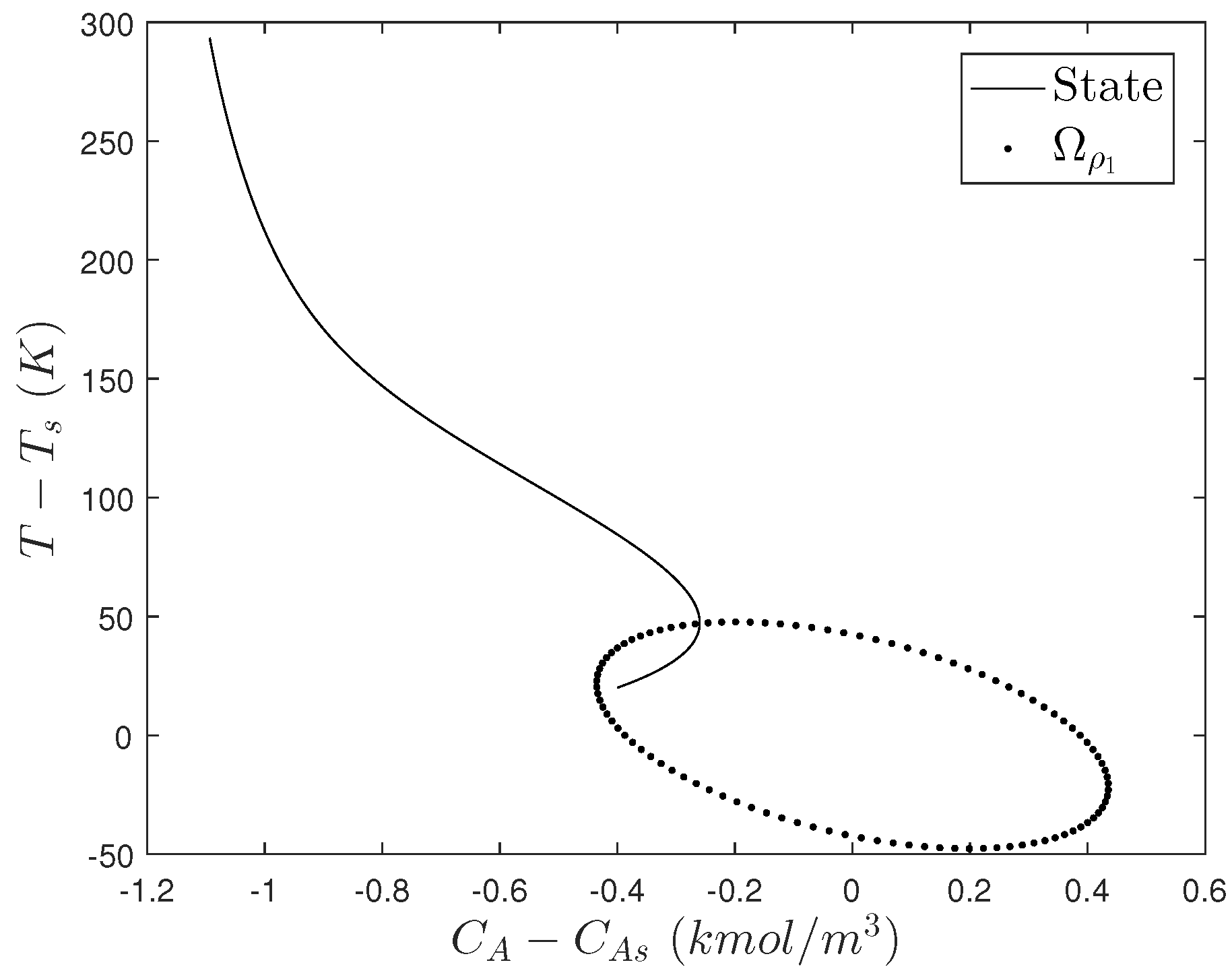
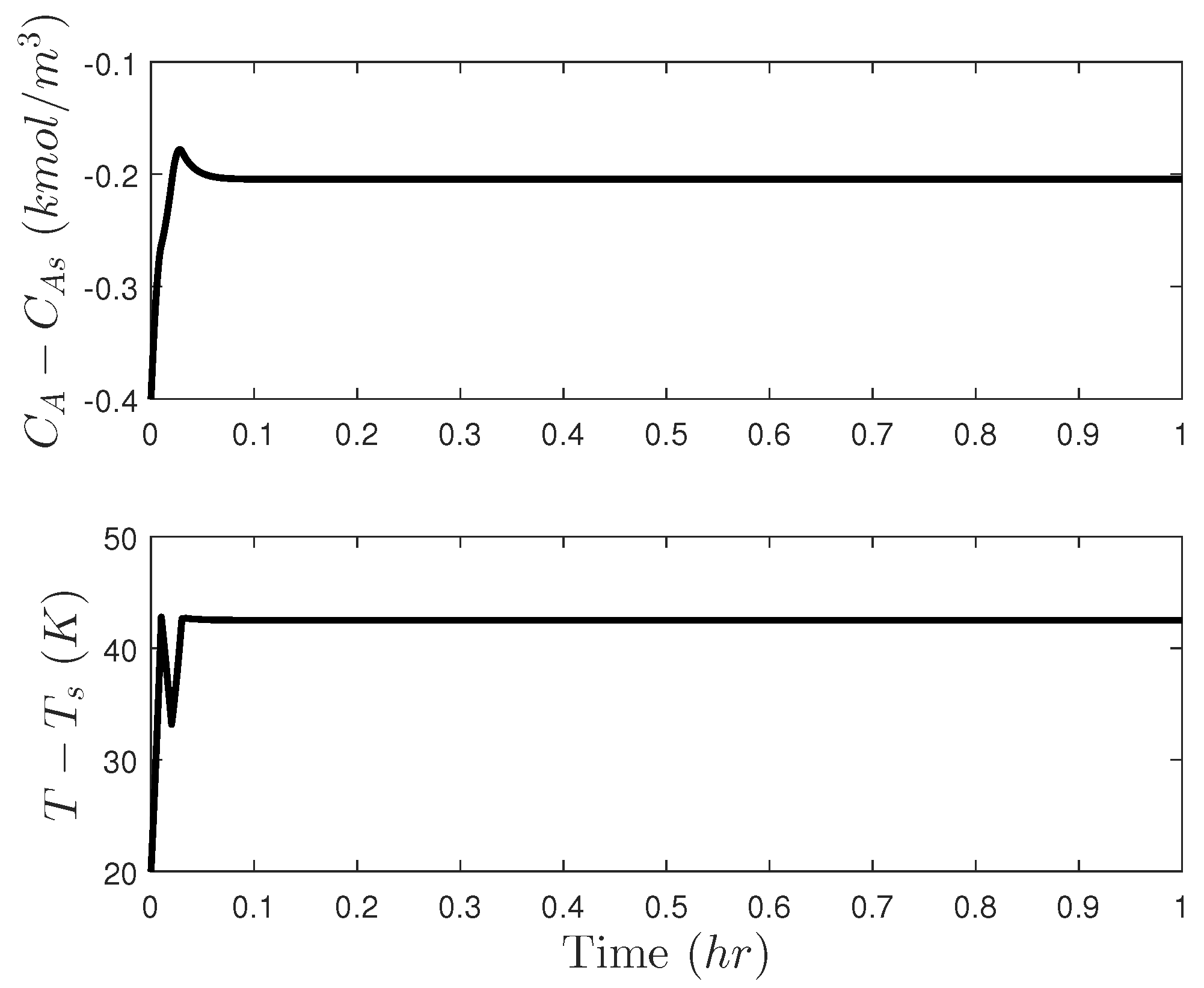
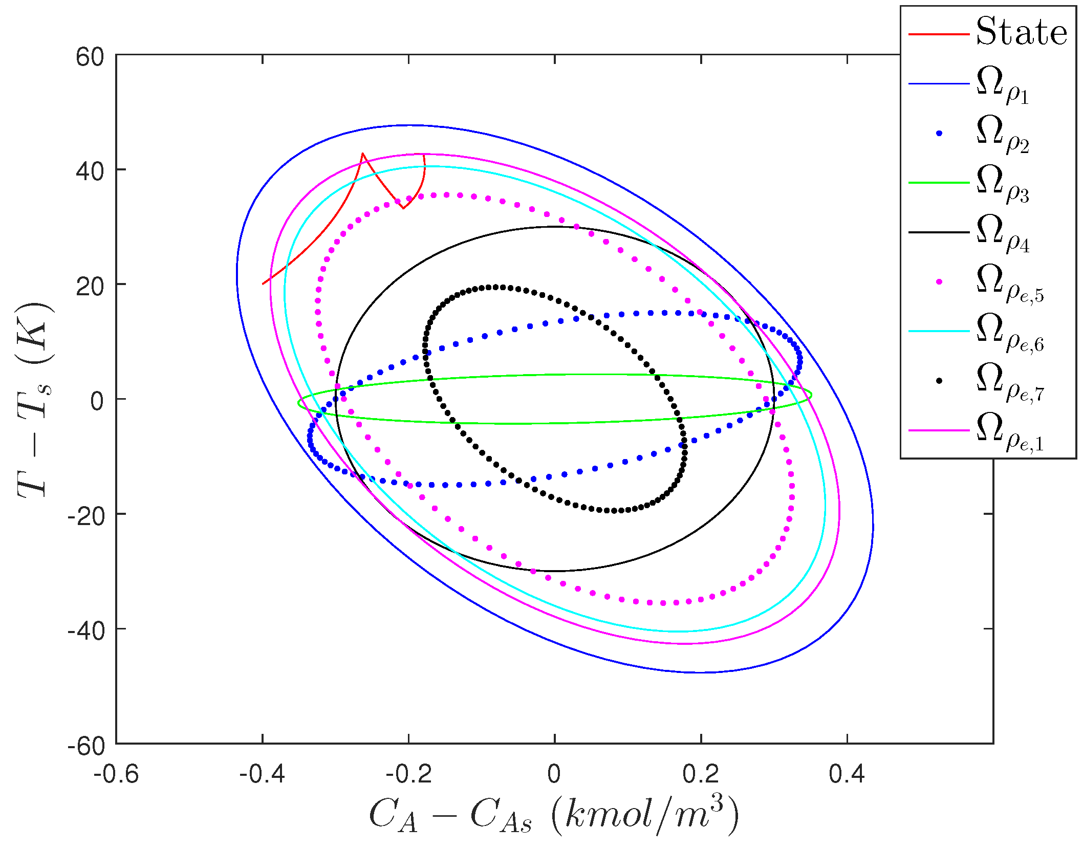
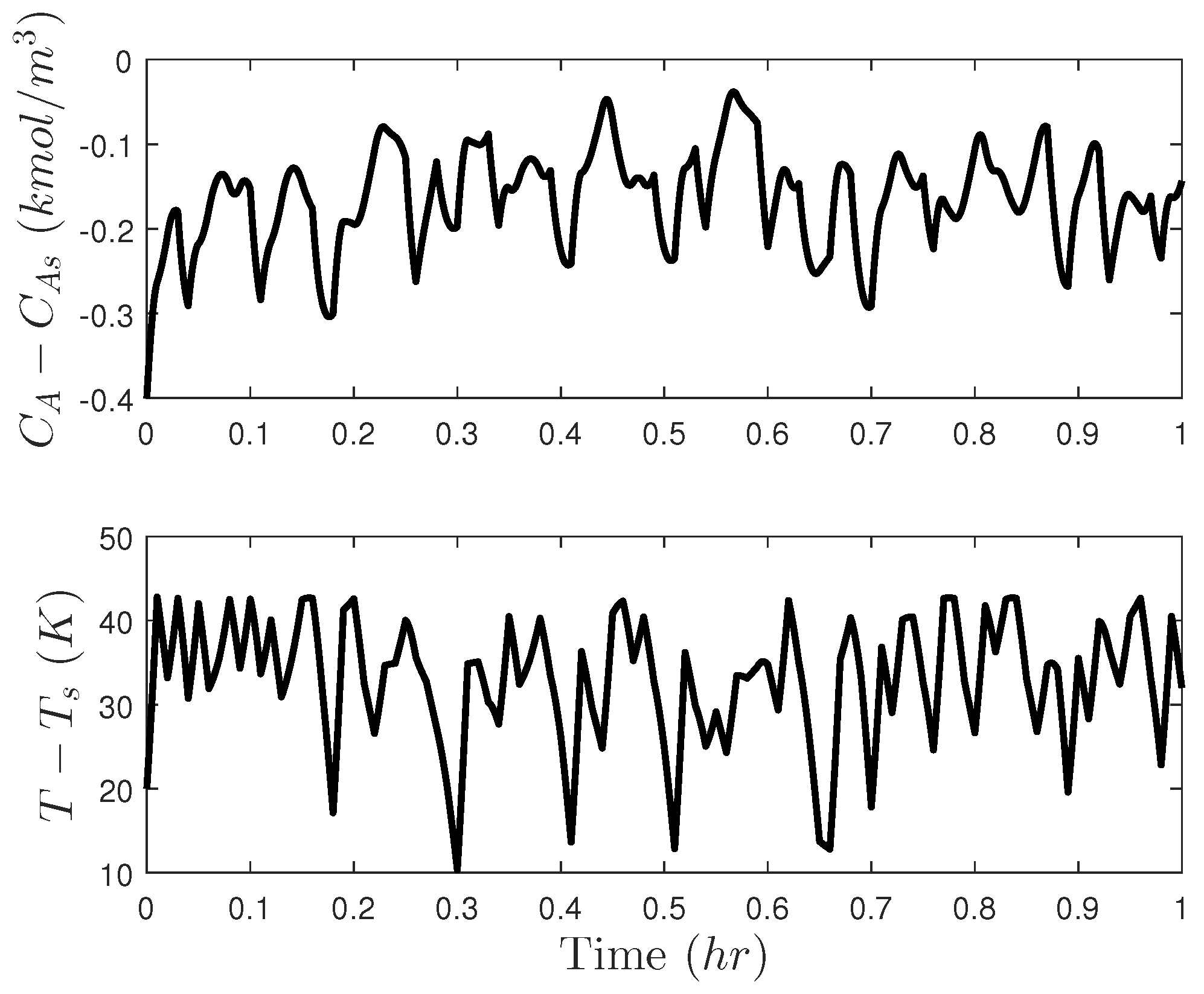
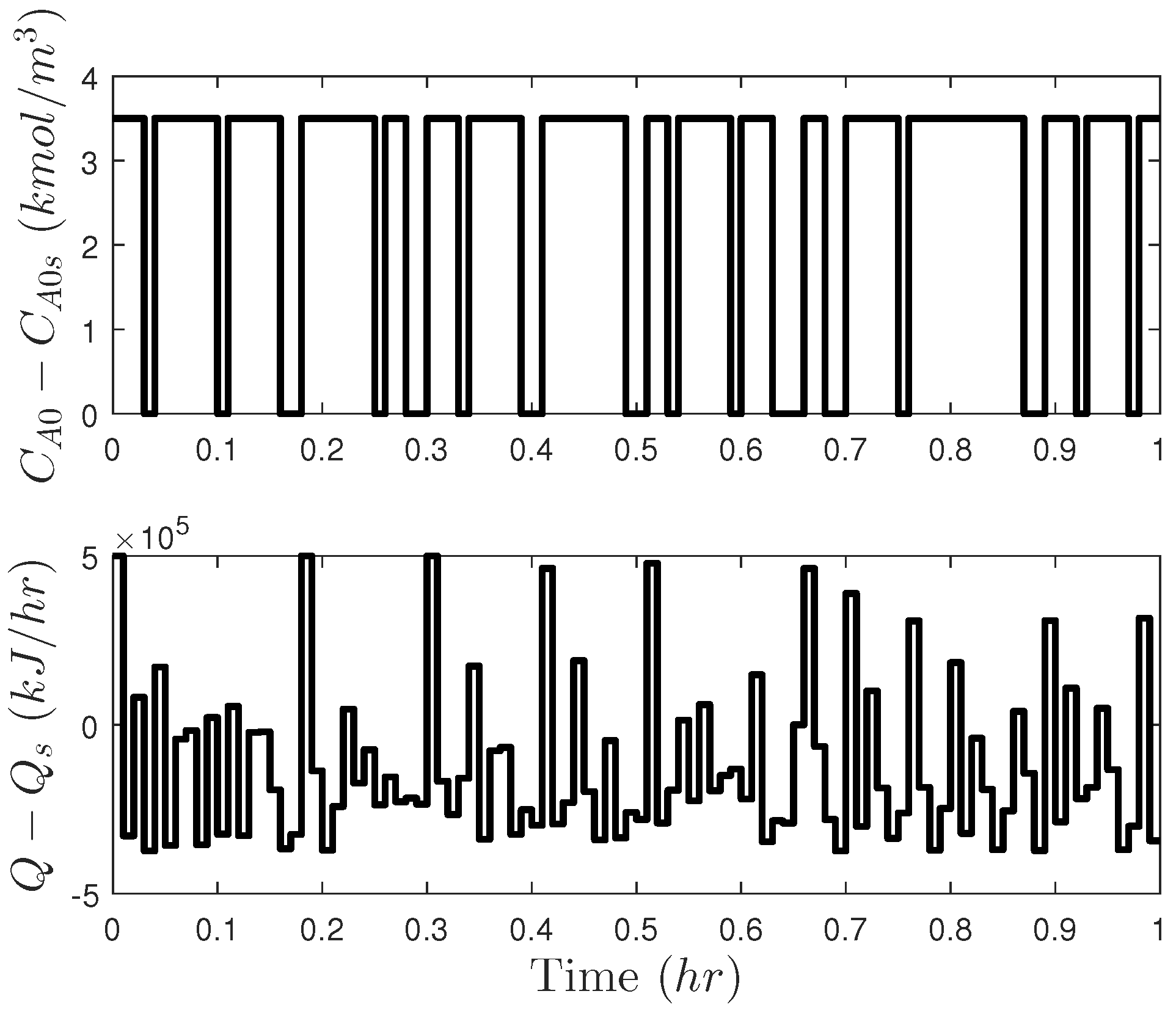
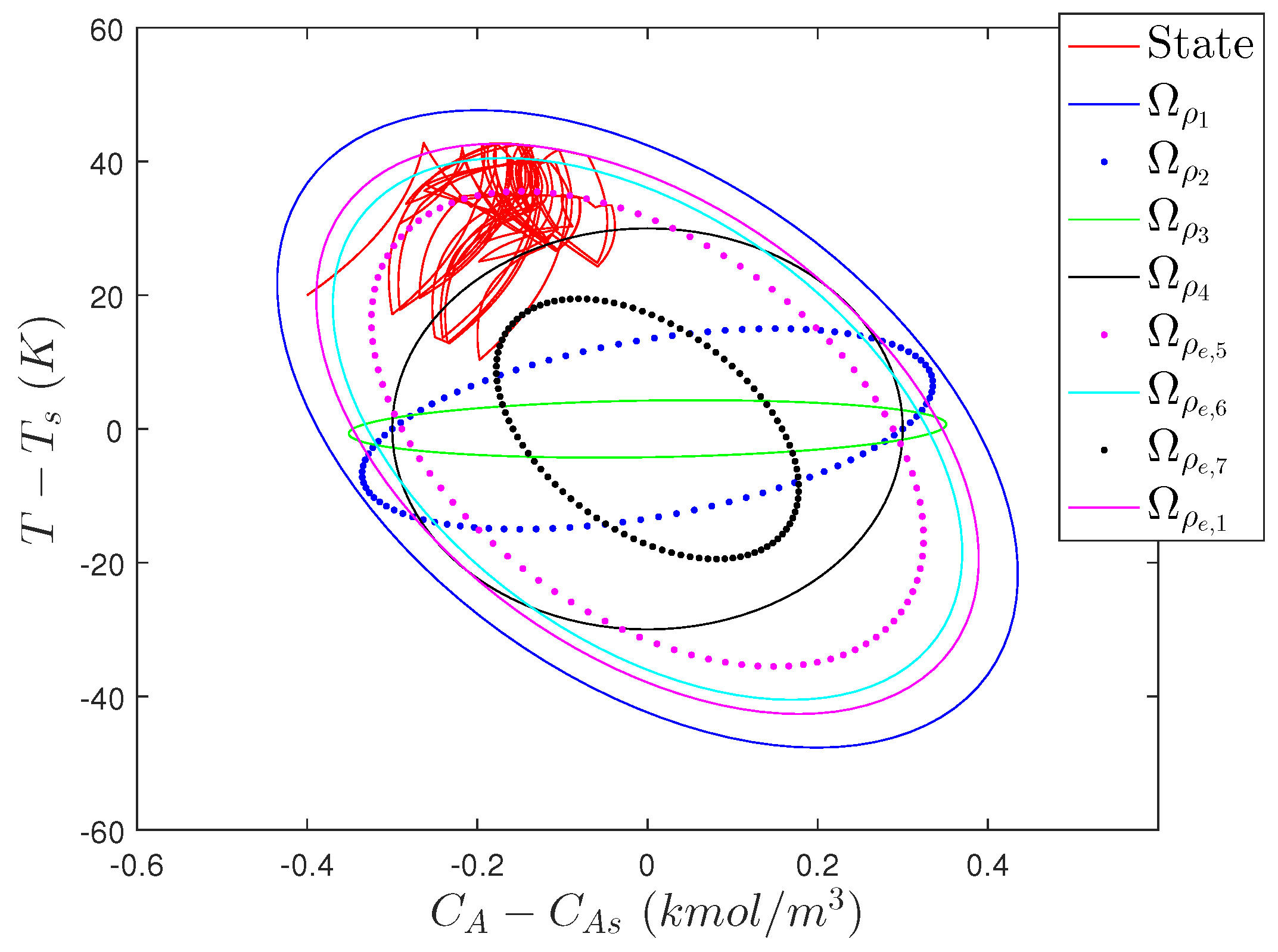
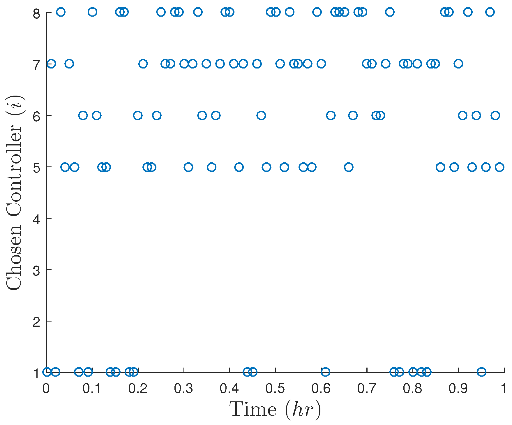
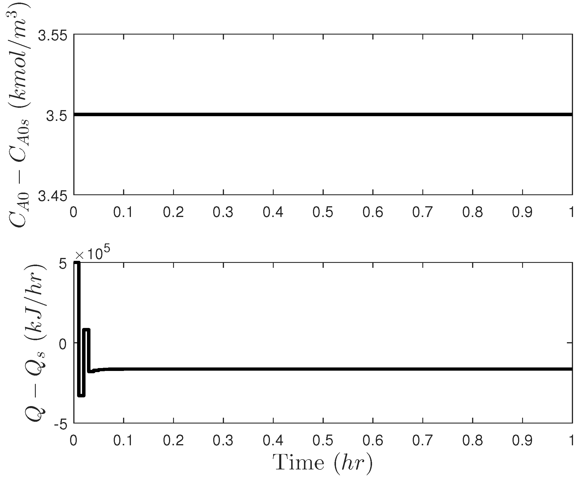
In solving Equations (50)–(60), the bounds on u 2 were multiplied by 10 5 . The false state measurement determined from Equations (55)–(60) was x 1 = 0 . 05207 kmol/m 3 and x 2 = 8 . 3934 K. Figure 2 demonstrates that when this state measurement is used at every sampling period for 10 sampling periods, the inputs computed are able to drive the temperature significantly above its threshold value x 2 = 55 K within a short time. When disturbances are added (specifically, simulations were performed with disturbances added to the right-hand sides of Equations (46) for w 1 and (47) for w 2 ) generated using the MATLAB functions rng(10) to generate a seed with normrnd to generate a pseudorandom number from a normal distribution with mean of zero and a standard deviation of 30 kmol/h (for w 1 ) and 3200 K/h (for w 2 ), with both inputs clipped when necessary to bound them such that | w 1 | 90 and | w 2 | 9600 , an unsafe situation is again set up in 10 sampling periods in which x 2 approaches 300 K as in Figure 2. The LMPC only receives state measurements, regardless of whether there are disturbances or not; therefore, if the same state measurement is given every time, it computes the same solution to the optimization problem every time and when this solution is able to drive the closed-loop state to an unsafe condition if continuously applied, the cyberattacker succeeds. The attack-defining concept posed here could be attempted for other attack goals as well, such as minimizing a profit-based objective function in Equations (50)–(54) to seek to compute an attack policy that financially attacks the plant or minimizing a production-based objective function to seek to attack the chemical supply from the plant.
Remark 4.
The CSTR example indicates an important difference between traditional safety thinking and thinking about cyberattacks. In traditional safety thinking, there will be unsafe operating conditions that might be considered very unlikely to be achieved; when considering cyberattacks, there can be deliberate attempts on the part of the attacker to set up unsafe operating conditions that might otherwise be very unlikely to be achieved. It is therefore important to seriously consider unlikely scenarios at the hazard analysis stage from the perspective of whether a cyberattack on the control system could lead them to occur.
Remark 5.
Though the cyberattack design methodology presented in this section suggests that cyberattacks on specific control designs might be developed computationally, the framework used in Equations (50)–(60) may not always achieve expected effects. Specifically, the initial condition determined by Equations (55)–(60) may not actually result in the control actions of Equations (50)–(54) being computed at each sampling time by the controller because the only feature of Equations (55)–(60) that seeks to associate x m e a s with u 1 , d e s i r e d and u 2 , d e s i r e d is a soft constraint rather than a hard constraint, and it is, therefore, not guaranteed to be met. Furthermore, Equations (55)–(60) do not account for the role of the objective function in affecting which inputs would actually be computed for a given state measurement. In this example, the false state measurement determined through Equations (50)–(60) was able to rapidly set up an unsafe scenario when used to cyberattack the LMPC; to develop attacks for other systems, it may be necessary to develop a more sophisticated method for determining the false state measurements or to use closed-loop simulations to determine if the false state measurements determined computationally provide an appropriate attack scenario with which to test research results. Finally, it should be noted that Equations (50)–(54) are not guaranteed to find an input that drives x 2 above its threshold in N sampling periods; whether or not this occurs may depend on the process dynamics, the input bounds, the initial condition, and also the number of sampling periods N over which the increase in x 2 is allowed to occur.

5.3. Deterring Sensor Measurement Falsification Cyberattacks on Safety: Creating Unpredictable Controller Outputs

The second “intuitive” approach seeks to address a perceived deficiency in the first “intuitive” approach, namely that the success of the cyberattacks in Section 5.2.1 was related to the fact that the cyberattacker could figure out the mapping between x ( t k ) and u by learning the control law. One idea for addressing this would be to develop sets of stabilizing control laws for a process and choose only one, randomly, at each sampling time. Then, if the inputs which the various potential control laws would compute for the same state measurement are significantly different, it may be more difficult for an attacker to determine an attack policy that, regardless of the control law chosen at a sampling time, will drive the closed-loop state to an unsafe condition (even if the attacker knew every potential control law).
Before we can consider such an approach, it must be established that randomization in the controller selection process can be achieved without impacting closed-loop stability under normal operation (i.e., in the absence of a cyberattack). Theory-based control designs with stability guarantees from an explicitly characterizable region of attraction even in the presence of disturbances (e.g., LMPC) are therefore attractive options for use in randomization strategies for control laws. In the remainder of this section, we present an example of a control design and implementation strategy that uses LMPC to incorporate randomness in process operation (with the goal of deterring cyberattacks by obscuring the mapping between a state measurement at a given sampling time and the input to be computed) with closed-loop stability guarantees under normal operation even in the presence of the randomness. However, like the design in Section 5.2, this design and its implementation strategy do not fundamentally prevent the existence of an input policy which could create an unsafe condition for some x ( t 0 ) X ¯ (when, for example, X ¯ = Ω ρ 1 ), and therefore if this design succeeds in preventing or delaying the impacts of cyberattacks, it does so more on the basis of chance than rigor, which is demonstrated below using the CSTR example.

5.3.1. Creating Unpredictable Controller Outputs: Incorporating Randomness in LMPC Design

The randomized LMPC design involves the development of n p controllers of the form of Equations (14)–(20) but where each can have a different Lyapunov function, Lyapunov function upper bound, and Lyapunov-based controller as follows:
min u ( t ) S ( Δ ) t k t k + N L e ( x ˜ ( τ ) , u ( τ ) ) d τ
s . t . x ˜ ˙ ( t ) = f ( x ˜ ( t ) , u ( t ) , 0 )
x ˜ ( t k ) = x ( t k )
x ˜ ( t ) X , t [ t k , t k + N )
u ( t ) U , t [ t k , t k + N )
V i ( x ˜ ( t ) ) ρ e , i , t [ t k , t k + N ) , if x ( t k ) Ω ρ e , i
V i ( x ( t k ) ) x f ( x ( t k ) , u ( t k ) , 0 ) V i ( x ( t k ) ) x f ( x ( t k ) , h i ( x ( t k ) ) , 0 ) if x ( t k ) Ω ρ i / Ω ρ e , i or t k t or δ = 1
where V i , ρ e , i , ρ i , and h i , i = 1 , , n p , play the roles in Equations (61)–(67) of V 1 , ρ e , 1 , ρ 1 , and h 1 , respectively, from Equations (14)–(20). Each combination of V i and h i is assumed to satisfy Equations (2)–(5) x Ω ρ i and Ω ρ e , i Ω ρ i . For j = 2 , , n p , the Ω ρ j should be subsets of Ω ρ 1 for reasons that will be clarified in Section 5.3.1.1. To introduce an additional aspect of randomness at each sampling time, the parameter δ is introduced in Equation (67). It can take a value of either 0 or 1, and one of those two values is randomly selected for it at each sampling time. δ = 1 corresponds to activation of the constraint of Equation (67) even when t k < t or x ( t k ) Ω ρ e , i .
With the n p controllers of the form of Equations (61)–(67) and the two possible values of δ in each of these LMPC’s at every sampling time, Equations (61)–(67) represent 2 n p potential controllers which may be selected at every sampling time (though if x ( t k ) Ω ρ i / Ω ρ e , i for n q of these controllers, Equations (61)–(67) with δ = 0 and δ = 1 are the same, such that the number of control laws is 2 n p n q ). One could consider other potential control options in addition, such as the Lyapunov-based controllers h i ( x ) , i = 1 , , n p . However, though all of these controllers are designed and are available in principle, they could cause closed-loop stability issues that require that not all of them be available to be randomly selected between at each sampling time. The conditions which determine which controllers are possibilities at a given sampling time should rely on the position of x ( t k ) in state-space and specifically whether x ( t k ) Ω ρ i for the i-th controller to be considered as a candidate.
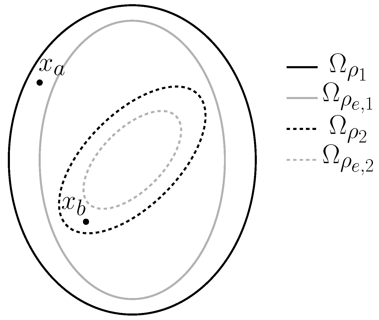
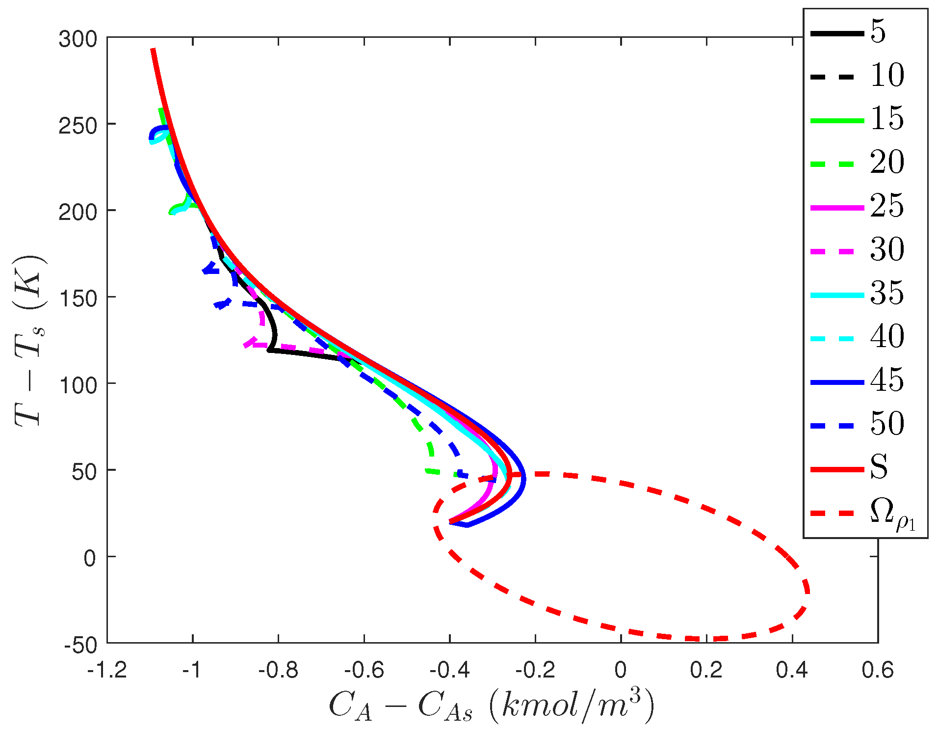
To exemplify this, consider the two level sets Ω ρ 1 and Ω ρ 2 and their subsets Ω ρ e , 1 and Ω ρ e , 2 shown in Figure 3. Two potential values of x ( t k ) are presented ( x a and x b ) to exemplify the role that the state-space location of x ( t k ) should play in determining which of the n p controllers of the form of Equations (61)–(67) or the Lyapunov-based controllers of the form h i ( x ( t k ) ) should be considered as candidates to randomly select between at a given sampling time. Consider first that x ( t k ) = x a . In this case, x ( t k ) Ω ρ 1 / Ω ρ e , 1 , and therefore, as described in Section 2.4, the LMPC of Equations (61)–(67) with i = 1 would be able to maintain the closed-loop state in Ω ρ 1 throughout the subsequent sampling period. It is also true that x ( t k ) Ω ρ e , 2 , so it may at first seem reasonable to consider that if the LMPC of Equations (61)–(67) is used with i = 2 , the constraint of Equation (67) could be activated to decrease the value of the Lyapunov function between two sampling periods and thereby drive the closed-loop state toward the origin using the properties of the Lyapunov-based controller and the constraint of the form of Equation (67) described in Section 2.4. However, the closed-loop stability properties delivered by the constraint of Equation (67) are developed with the requirement that Equations (2)–(5) must hold within the stability region and that x ( t k ) must be in this stability region. When x ( t k ) Ω ρ 2 , these properties are not guaranteed to hold. Therefore, when x ( t k ) = x a in Figure 3, the LMPC of Equations (61)–(67) with i = 2 would not be a wise choice to randomly select at a given sampling time. Similarly, h 2 ( x ( t k ) ) is guaranteed to maintain closed-loop stability when x ( t k ) Ω ρ 2 , but if h 2 ( x ( t k ) ) is applied when x ( t k ) = x a , x ( t k ) Ω ρ 2 and therefore the stability properties are not guaranteed to hold.
In contrast, consider the potential initial condition x ( t k ) = x b . In this case, x ( t k ) Ω ρ 1 and Ω ρ 2 . Consequently, Equations (61)–(67) with i = 1 or i = 2 (for δ = 1 or δ = 0 ), h 1 ( x ( t k ) ) , and h 2 ( x ( t k ) ) can all maintain closed-loop stability of the process of Equation (1), and therefore all could be considered as potential control designs between which to randomly select at t k . This indicates that the location of x ( t k ) in state-space should be checked with respect to Ω ρ i , i = 1 , , n p , before developing a candidate set of controllers to randomly select between at t k . It should be noted, however, that if Ω ρ i , i = 2 , , n p , are subsets of Ω ρ 1 , then at each sampling time, Equations (61)–(67) with i = 1 and δ = 0 , Equations (61)–(67) with i = 1 and δ = 1 , and h 1 ( x ( t k ) ) are all candidate controllers that can maintain closed-loop stability. If x ( t k ) is in the intersection of additional level sets, there are additional candidate controllers which could be randomly selected between. Therefore, the minimum number of candidate controllers is 3 (or 2 if x ( t k ) Ω ρ 1 / Ω ρ e , 1 such that Equations (61)–(67) with δ = 0 and δ = 1 are equivalent), with more potentially being possible, especially as more stability regions with more intersections are developed.
Taking the above considerations into account, the implementation strategy for the LMPC design of Equations (61)–(67) is proposed as follows:
Step 1. At t k , a random integer j between 1 and 2 n p is selected, and δ is randomly selected to be zero or one.
Step 2. If j { 2 , , n p } , set i = j . If j { n p + 2 , , 2 n p } , set i = j n p . Verify that V i ( x ( t k ) ) Ω ρ i . If yes, move to Step 3. If not, return to Step 1.
Step 3. If j is a number between 1 and n p , use the LMPC of Equations (61)–(67) with i = j and the selected value of δ . If j = n p + d , d = 1 , , n p , set u = h d ( x ( t k ) ) .
Step 4. Apply the control action computed for t k to the process of Equation (1).
Step 5. t k t k + 1 . Return to Step 1.
Remark 6.
To prevent the possibility that the same index that is found to not meet the conditions in Step 2 at t k will be selected multiple times as Steps 1 and 2 are repeated until a value of j is found for which V i ( x ( t k ) ) Ω ρ i , indexes that cause V i ( x ( t k ) ) Ω ρ i can be removed in the random integer selection procedure in Step 1 at t k as they are identified before they force the algorithm to return to Step 1.

5.3.1.1. Stability Analysis of Randomized LMPC

In this section, we develop sufficient conditions required for the randomized LMPC implementation strategy to provide closed-loop stability of the nonlinear process of Equation (1) under this implementation strategy and feasibility of the LMPC of Equations (61)–(67) when it is selected via the implementation strategy in the absence of a cyberattack in Section 5.3.1 to be used in determining a control action at a given sampling time. We first introduce two propositions that will then be used in proving the main results.
Proposition 1.
Refs. [60,82] Consider the systems
x ˙ a ( t ) = f ( x a ( t ) , u ( t ) , w ( t ) )
x ˙ b ( t ) = f ( x b ( t ) , u ( t ) , 0 )
with initial states x a ( t 0 ) = x b ( t 0 ) Ω ρ 1 . There exists a function f W of class K such that:
| x a ( t ) x b ( t ) | f W ( t t 0 )
for all x a ( t ) , x b ( t ) Ω ρ 1 and all w ( t ) W with:
f W ( τ ) = L w θ L x ( e L x τ 1 )
Proposition 2.
Refs. [60,82] Consider the Lyapunov function V i ( · ) of the system of Equation (1). There exists a quadratic function f V , i ( · ) such that:
V i ( x ) V i ( x ^ ) + f V , i ( | x x ^ | )
for all x , x ^ Ω ρ i with
f V , i ( s ) = α 4 , i ( α 1 , i 1 ( ρ i ) ) s + M v , i s 2
where M v , i > 0 is a constant.
Proposition 3.
Ref. [62] Consider the Lyapunov-based controller h i ( x ) that meets Equations (2)–(5) with Lyapunov function V i ( · ) , applied in sample-and-hold to the system of Equation (1). If ρ i > ρ e , i > ρ min , i > ρ s , i , and θ > 0 , Δ > 0 , and ϵ w , i > 0 satisfy:
α 3 , i ( α 2 , i 1 ( ρ s , i ) ) + L x , i M Δ + L w , i θ ϵ w , i / Δ
then x ( t k ) Ω ρ i / Ω ρ s , i ,
V i ( x ( t ) ) V i ( x ( t k ) )
and x ( t ) Ω ρ i for t [ t k , t k + 1 ) . Furthermore, if ρ min , i is defined as follows:
ρ min , i = max { V i ( x ( t + Δ ) ) : V i ( x ( t ) ) ρ s , i }
then the closed-loop state is ultimately bounded in Ω ρ min , i in the sense that:
lim sup t | x ( t ) | Ω ρ min , i
Theorem 1.
Consider the system of Equation (1) in closed-loop under the implementation strategy of Section 5.3.1 based on controllers h i ( x ) that satisfy Equations (2)–(5), and consider that the conditions in Proposition 3 hold. Let ϵ w , i > 0 , Δ > 0 , ρ i > ρ e , i > ρ min , i > ρ s , i satisfy:
ρ e , i ρ i f V , i ( f W ( Δ ) )
and Equations (74) and (76), for i = 1 , , n p , and Ω ρ e , j Ω ρ e , 1 , j = 2 , , n p . If x ( t 0 ) Ω ρ 1 and N 1 , then the state x ( t ) of the closed-loop system is always bounded in Ω ρ 1 .
Proof. 
The proof consists of two parts. In the first part, we demonstrate that despite the random selection of a control law in Step 1 of the implementation strategy in Section 5.3.1, a characterizable control action is applied at every sampling time, and the LMPC of Equations (61)–(67) is feasible at every sampling time at which it is used for determining the control action to apply to the process. In the second part, we prove the results of Theorem 1.
Part 1. To demonstrate that an input with characterizable properties is returned by the implementation strategy of Section 5.3.1 at every sampling time to be applied to the process, we note that one of two inputs is returned at every sampling time: a) a control action computed by the LMPC of Equations (61)–(67) with i = j where x ( t k ) Ω ρ j or b) a Lyapunov-based controller h j ( x ( t k ) ) where x ( t k ) Ω ρ j .
In case (a), a solution to the LMPC of Equations (61)–(67) must have the characterizable property that it met the constraints of the LMPC because the LMPC always has at least one feasible solution. Specifically, h i ( x ˜ ( t q ) ) , q = k , , k + N 1 , t [ t q , t q + 1 ) , with i = j , is a feasible solution to the optimization problem of Equations (61)–(67) when x ( t k ) Ω ρ j . It causes the constraint of Equation (64) to be met because h i ( x ˜ ( t q ) ) , q = k , , k + N 1 , t [ t q , t q + 1 ) , maintains the closed-loop state in Ω ρ j Ω ρ 1 by Proposition 3, and the state constraint of Equation (64) is met for all states in Ω ρ 1 . h i ( x ) in sample-and-hold also satisfies the input constraint of Equation (65) by Equation (5). From Proposition 3, it causes the constraint of Equation (66) to be met when x ( t k ) Ω ρ j , and it trivially satisfies the constraint of Equation (67). Notably, the feasibility of h i ( x ) in sample-and-hold is true regardless of whether δ = 1 or δ = 0 because this is a feasible solution to all constraints of the optimization problem.
In case (b), the control action applied to the process is also characterizable because it is a control action that meets Proposition 3. Therefore, regardless of the control action applied at t k , the control action has characterizable properties which can be used in establishing closed-loop stability. Furthermore, whenever Equations (61)–(67) are used to determine an input at a given sampling time, a feasible solution to this optimization problem always exists because it is ensured that x ( t k ) Ω ρ i before the solution is obtained, and the feasibility of h i ( x ˜ ( t q ) ) , q = k , , k + N 1 , t [ t q , t q + 1 ) was demonstrated to hold above as long as x ( t k ) Ω ρ i .
Part 2. In this part, we prove that even with a control law randomly selected at every sampling time according to the implementation strategy in Section 5.3.1, the closed-loop state is maintained within Ω ρ 1 for all times if x ( t 0 ) Ω ρ 1 .
To demonstrate this, we first consider the case that at a given sampling time, a control law of the form of Equations (61)–(67) with i = j when x ( t k ) Ω ρ j is selected. In this case, either the constraint of Equation (66) is activated (if x ( t k ) Ω ρ e , i ), the constraint of Equation (67) is activated (if x ( t k ) Ω ρ i / Ω ρ e , i , t k t , or δ = 1 ), or both are activated (as may occur, for example, if t k t or δ = 1 but x ( t k ) Ω ρ e , i ).
Consider first the case that Equation (66) is activated. In this case, application of Proposition 2 (assuming that x ( t ) Ω ρ i for t [ t k , t k + 1 ) ) gives:
V i ( x ( t ) ) V i ( x ˜ ( t ) ) + f V , i ( | x ( t ) x ˜ ( t ) | )
for t [ t k , t k + 1 ) . Applying the constraint of Equation (66) and Proposition 1, we obtain that:
V i ( x ( t ) ) ρ e , i + f V , i ( f W ( | t t k | ) ) ρ e , i + f V , i ( f W ( Δ ) )
for t [ t k , t k + 1 ) . When Equation (78) holds, V i ( x ( t ) ) ρ i , for t [ t k , t k + 1 ) , which validates the assumption used in deriving this result and guarantees that x ( t ) Ω ρ i for t [ t k , t k + 1 ) when x ( t k ) Ω ρ e , i and the LMPC of Equations (61)–(67) is used to determine the input to the process of Equation (1). Because Ω ρ i Ω ρ 1 , x ( t ) Ω ρ 1 for t [ t k , t k + 1 ) .
Consider now the case that the constraint of Equation (67) is activated. In this case, we have from this constraint and Equation (3) that
V i ( x ( t k ) ) x f ( x ( t k ) , u ( t k ) , 0 ) V i ( x ( t k ) ) x f ( x ( t k ) , h i ( x ( t k ) ) , 0 ) α 3 , i ( | x ( t k ) | )
from which we can obtain:
V i ( x ( t ) ) x f ( x ( t ) , u ( t k ) , w ( t ) ) = V i ( x ( t ) ) x f ( x ( t ) , u ( t k ) , w ( t ) ) V i ( x ( t k ) ) x f ( x ( t k ) , u ( t k ) , 0 ) + V i ( x ( t k ) ) x f ( x ( t k ) , u ( t k ) , 0 ) V i ( x ( t ) ) x f ( x ( t ) , u ( t k ) , w ( t ) ) V i ( x ( t k ) ) x f ( x ( t k ) , u ( t k ) , 0 ) α 3 , i ( | x ( t k ) | ) L x , i | x ( t ) x ( t k ) | + L w , i | w | α 3 , i ( | x ( t k ) | ) L x , i M Δ + L w , i θ α 3 , i ( | x ( t k ) | )
for t [ t k , t k + 1 ) , where the last inequality follows from Equations (7) and (8). Furthermore, if x ( t k ) Ω ρ i / Ω ρ s , i , we can obtain from Equation (82) that:
V i ( x ( t ) ) x f ( x ( t ) , u ( t k ) , w ( t ) ) L x , i M Δ + L w , i θ α 3 , i ( α 2 , i 1 ( ρ s , i ) )
If Equation (74) holds, then
V i ( x ( t ) ) x f ( x ( t ) , u ( t k ) , w ( t ) ) ϵ w , i / Δ
Integrating Equation (84) gives that V i ( x ( t ) ) V i ( x ( t k ) ) , t [ t k , t k + 1 ) , such that if x ( t k ) Ω ρ i / Ω ρ s , i , then x ( t ) Ω ρ i , t [ t k , t k + 1 ) .
If instead x ( t k ) Ω ρ s , i Ω ρ i , then from Equation (76), x ( t ) Ω ρ min , i Ω ρ i for t [ t k , t k + 1 ) . Therefore, if Equations (61)–(67) are used to compute the input trajectory at t k and x ( t k ) Ω ρ i and Equation (67) is applied, x ( t ) Ω ρ i for t [ t k , t k + 1 ) (this holds regardless of whether Equation (66) is simultaneously applied since this proof relied only on whether Equation (67) is applied and not whether the other constraints were simultaneously applied). Because Ω ρ i Ω ρ 1 , this indicates that when the LMPC of Equations (61)–(67) is used with the constraint of Equation (67) activated to determine the control action at t k when x ( t k ) Ω ρ i , then x ( t ) Ω ρ 1 for t [ t k , t k + 1 ) .
Finally, consider the case that x ( t k ) Ω ρ i and h i ( x ( t k ) ) is used to control the process of Equation (1) from t k to t k + 1 . In this case, the following holds:
V i ( x ( t k ) ) x f ( x ( t k ) , h ( x ( t k ) ) , 0 ) α 3 , i ( | x ( t k ) | )
as follows from Equation (3). Using a similar series of steps as in Equation (82), we obtain:
V i ( x ( t ) ) x f ( x ( t ) , h ( x ( t k ) ) , w ( t ) ) L x , i M Δ + L w , i θ α 3 , i ( | x ( t k ) | )
If x ( t k ) Ω ρ i / Ω ρ s , i , then as for Equation (83), we obtain:
V i ( x ( t ) ) x f ( x ( t ) , h ( x ( t k ) ) , w ( t ) ) L x , i M Δ + L w , i θ α 3 , i ( α 2 , i 1 ( ρ s , i ) )
If Equation (74) holds, then we can use a similar series of steps as for Equation (84) to derive that V i ( x ( t ) ) V i ( x ( t k ) ) , t [ t k , t k + 1 ) , such that if x ( t k ) Ω ρ i / Ω ρ s , i , then x ( t ) Ω ρ i , t [ t k , t k + 1 ) . If x ( t k ) Ω ρ s , i , then when Equation (76) holds, we obtain that x ( t ) Ω ρ min , i , t [ t k , t k + 1 ) , so that x ( t ) Ω ρ i for t [ t k , t k + 1 ) . Since Ω ρ i Ω ρ 1 , we again obtain that if x ( t k ) Ω ρ i and h i ( x ( t k ) ) is applied for t [ t k , t k + 1 ) , then x ( t ) Ω ρ 1 , t [ t k , t k + 1 ) .
The above results indicate that throughout every sampling period, if the conditions of Theorem 1 hold and the implementation strategy in Section 5.3.1 is used, then the closed-loop state does not leave Ω ρ 1 , implying that it also holds throughout all time if x ( t 0 ) Ω ρ 1 . This completes the proof. ☐
Remark 7.
Theorem 1 only speaks to the closed-loop state remaining in a bounded region of operation. If the randomness is removed and the i = 1 controller is selected to be used with the constraint of Equation (67) activated for all subsequent times (i.e., Equations (14)–(20) with t > t ), the closed-loop state is guaranteed to be ultimately bounded in a neighborhood of the origin [60]. If the randomness is not removed but t > t in Equations (61)–(67), the i-th controller will cause V i ( x ( t ) ) < V i ( x ( t k ) ) , t ( t k , t k + 1 ] as noted in Section 2.4. However, consider the case that x ( t k ) Ω ρ i and x ( t k ) Ω ρ z , but the i-th controller is selected at t k . The decrease in V i throughout the sampling period as a result of using the i-th controller does not necessarily imply that V z ( x ( t ) ) < V z ( x ( t k ) ) , t ( t k , t k + 1 ] . If the randomness is removed, however, and only the i = 1 controller is used with t > t , V 1 ( x ( t ) ) < V 1 ( x ( t k ) ) , t ( t k , t k + 1 ] in every sampling period (i.e., a continuous decrease of the same Lyapunov function is ensured so that the closed-loop state is guaranteed to move to lower level sets of this Lyapunov function and not to again leave them) until the closed-loop state reaches Ω ρ s , 1 , after which point it remains ultimately bounded in Ω ρ min , 1 . Another idea for driving the closed-loop state to a neighborhood of the origin with a randomized LMPC implementation strategy would be to change the implementation strategy at t to only allow controllers to be selected in Steps 1-2 for which V 1 and h 1 are used in their design (e.g., h 1 and the i = 1 LMPC) so that each of the potential controllers would cause a decrease in the same Lyapunov function value over time.
Remark 8.
The stability analysis reveals that despite the intuitive nature of the approach for deterring cyberattackers, it suffers the same problem as the controller in Section 5.2; namely, it does not meet Definition 4, and once the controller learns the implementation strategy itself, he or she could develop an attack policy that is not guaranteed to maintain closed-loop stability according to the proof methodology above. We can see a potential for the lack of resilience by referring again to Figure 3 and noting that if the actual state measurement is at x a , the closed-loop stability proof relies on the i = 2 controller not being an option; however, a false state measurement of x b may cause the i = 2 controller to be chosen when x ( t k ) = x a , such that the conditions required for the closed-loop stability proof in Theorem 1 (i.e., that the implementation strategy in Section 5.3.1 is correctly followed) do not hold. However, the closed-loop stability issues with the proposed design in the presence of a cyberattack are deeper than this; the problem is not necessarily that the control action computed by a controller that would not otherwise have been selected is used, but rather that regardless of whether that controller should have been allowed to be used per the implementation strategy in Section 5.3.1 is used or not, the input applied to the process has no relationship to the state in the sense that, for example, the state constraints in Equations (66) and (67) are not necessarily met (or even close to being met) by the actual process state even if the controller used at t k indicated feasibility of the control action with respect to these constraints. This is because the controller is using a different initial condition than the actual process initial condition and therefore will compute, potentially, a state trajectory under the input selected as optimal by the LMPC that is very different from the actual process state trajectory under that same input, even in the absence of disturbances/plant-model mismatch. Mismatch is introduced by the cyberattack at the initial condition for the model of Equation (62).

5.3.2. Problems with Incorporating Randomness in LMPC Design

In this section, we demonstrate the use of the randomized LMPC for the CSTR example of Section 5.2.1 during routine operation and also in the case that false state measurements are provided to demonstrate that the randomized LMPC implementation strategy can maintain closed-loop stability under normal operation, but may at best in certain sensor cyberattack cases only delay an unsafe condition from being reached (i.e., randomness by itself, without giving the properties in Definition 4, does not create cyberattack resilience in control). We first develop the set of LMPC’s to be used to control the process of Equations (46) and (47). We begin by developing seven (i.e., n p = 7 ) potential combinations of V i , h i , Ω ρ i , and Ω ρ e , i . The form of each V i is x T P i x , where P i is a symmetric positive definite matrix of the following form:
P 11 P 12 P 12 P 22
Sontag’s control law [80] was used to set the value of the component of every h i = [ h i , 1 h i , 2 ] T corresponding to u 2 as follows:
h i , 2 ( x ) = L f ˜ V i + L f ˜ V i 2 + L g ˜ 2 V i 4 L g ˜ 2 V i , if L g ˜ 2 V i 0 0 , if L g ˜ 2 V i = 0
where if h i , 2 fell below or exceeded the upper or lower bound on u 2 , h i , 2 was saturated at the respective bound. L f ˜ V i and L g ˜ k V i represent the Lie derivatives of V i with respect to f ˜ and g ˜ k , k = 1 , 2 . For simplicity, h i , 1 was taken to be 0 kmol/m 3 for i = 1 , , 7 . Using the values of the entries of each P i associated with each V i in Table 3 and the associated h i , i = 1 , , 7 , the stability regions in Table 3 were obtained by discretizing the state-space and choosing an upper bound on each Lyapunov function in a region of state-space where V ˙ i was negative at the discretized points under the controller h i , i = 1 , , 7 (the discretization was performed in increments of 0.01 kmol/m 3 in C A for C A between 0 and 4 kmol/m 3 , and in increments of 1 in T for T between 340 and 560 K ). Subsets of the stability regions were selected to be Ω ρ e , i with the goal of allowing several different control laws to be developed. For i = 2 , , 7 , Ω ρ i Ω ρ 1 . The value of ρ e , i was not more than 80% of ρ i in each case.
Initially, we evaluate the closed-loop stability properties of the process of Equations (46) and (47) for normal operation under the randomized LMPC implementation strategy and, for comparison, under the i = 1 LMPC used for all times. The process was initialized from x i n i t = [ 0 . 4 kmol/m 3 20 K ] T . For the randomized LMPC design, the implementation strategy in Section 5.3.1 was followed with the exception that, for simplicity, δ was set to 0 at every sampling time, and only h 1 ( x ) was considered as a candidate controller at a given sampling time as an alternative to controllers in Table 3. Therefore, at every sampling time, both the LMPC of Equations (61)–(67) with i = 1 and h 1 ( x ) were allowable control actions, and the i-th controller in Table 3 was also allowable if x ( t k ) Ω ρ i . The simulations were implemented in MATLAB using fmincon and the seed rng(5) and random integer generation function randi when the randomized LMPC implementation strategy was used. The integration step for the model of Equations (46) and (47) was set to 10 4 h, N = 10 , and Δ = 0 . 01 h, with 1 h of operation used. The Lyapunov-based stability constraint activated when x ( t k ) Ω ρ e , i was enforced at the end of every sampling period in the prediction horizon, and whenever the Lyapunov-based stability constraint involving the time-derivative of the Lyapunov function was enforced, the other Lyapunov-based constraint was implemented at the end of the sampling periods after the first. The initial guess provided to fmincon in both cases was the steady-state input vector. The maximum and minimum values of u 2 were multiplied by 10 5 in numerically solving the optimization problem.
Figure 4, Figure 5 and Figure 6 show the state, input, and state-space trajectories resulting from controlling the process with one LMPC throughout the time period of operation, and Figure 7, Figure 8 and Figure 9 show the results of controlling the LMPC with one of the eight potential control laws selected at every sampling time, but depending on the position of the state measurement in state-space. The figures indicate that both the single LMPC implemented over time and the randomized LMPC implementation strategy were able to maintain the closed-loop state within Ω ρ 1 . Figure 10 shows which controller (i in Table 3) was selected by the randomized LMPC implementation strategy at each sampling time. Notably, the control laws associated with i = 2 , 3, and 4 in Table 3 were not chosen, which is consistent with the requirement that a control law can only be available to be selected if x ( t k ) Ω ρ i (from Figure 9, we see that the closed-loop state did not enter, for example, Ω ρ 2 and Ω ρ 3 , and the results of the simulations indicate that though the closed-loop state sometimes entered Ω ρ 4 as shown in Figure 9, it was never in this region at a sampling time, which explains why these controllers were never selected by the randomized implementation strategy). The time-integral of Equation (48) was monitored for the process of Equations (46) and (47) under the inputs applied to the process, and also for steady-state operation. For the single LMPC implemented over time, it evaluated to 32.2187, while for the randomized LMPC implementation strategy, it evaluated to 27.7536. There is some profit loss due to the randomized LMPC implementation strategy, and also large variations in states and inputs shown in Figure 7 and Figure 8. If the randomized LMPC implementation strategy was able to deter cyberattacks, one could consider whether that made the variations and profit loss acceptable. Despite the decrease in profits due to the randomization, both the single LMPC over time and the LMPC’s implemented within the randomized implementation strategy significantly outperformed steady-state operation, which had a value of the time-integral of Equation (48) of 13.8847.
After analyzing normal operation for the LMPC and randomized LMPC implementation strategy, we look at differences in their response to the cyberattack policy determined in Section 5.2.1, where the attack on the sensors is simulated for 10 sampling periods and the process is initialized at x i n i t . The metric that we use for comparing the results in the two scenarios is the time until the closed-loop state exceeds its threshold of 55 K for x 2 (as x 2 > 55 K occurs outside the stability region, the closed-loop state exits the stability region before this unsafe condition is reached). For the single LMPC, x 2 first exceeds it threshold around 0.0142h. In the case of the randomized LMPC, different input policies (i.e., different sequences of randomly selected control laws) give different behavior in the presence of the cyberattack. Therefore, in Table 4, we present the approximate time that x 2 exceeds its threshold for 10 different arguments provided to the MATLAB seeding function rng to create 10 different seeds for the random number generator that selects which control law to randomly select at each sampling time. The table indicates that the randomization may slightly delay the time at which x 2 first exceeds its threshold compared to the case that the single LMPC is used. However, in none of the cases simulated was it able to prevent the cyberattack from driving the value of x 2 above its threshold in 0 . 1 h of operation. If a cyberattacker believes that some delay in the attack may cause him or her to be caught, this strategy may help with deterring some types of attacks. However, the results indicate that it is not cyberattack-resilient according to Definition 4. Figure 11 shows the results of the simulations for 0 . 1 h with the randomized LMPC implementation strategy for different arguments of rng in state-space.
Figure 12 displays data on the inputs and value of V 1 ( x ) over time under both the randomized LMPC implementation strategy and the single LMPC, as well as the selected control law among the 8 possibilities at each sampling time in the case that the argument of rng is set to 20. This figure suggests that some of the difficulty with maintaining the closed-loop state in a bounded region under the attack is that for the falsified state measurement, the available controllers (the i = 3 and i = 4 controllers are not available because the false state measurement that the controller receives and uses in determining which control laws should be made available according to the randomized LMPC implementation strategy is outside of Ω ρ 3 and Ω ρ 4 ) compute inputs with similarities to each other and to the inputs which the single LMPC would compute in the sense that they are either close in value or create similar effects on the closed-loop state (i.e., the fact that different control laws may be chosen to compute an input is not very effective in this case at obscuring the mapping between x ( t k ) and the inputs applied to the process). From Figure 12, we see that all of the available control laws were used at some point, but the inputs computed in every case except for the i = 8 controller were close to those of the single LMPC, and the i = 8 controller was also not effective at causing a direction change in the value of V 1 , despite that it has some more noticeable differences compared to the trajectory computed by the single LMPC.
The attack policy chosen plays a role in the amount of delay in the success of an attack which the randomized LMPC implementation strategy of Section 5.3.1 may cause. For example, consider instead the falsified initial condition x 1 = 0 . 0632 kmol/m 3 and x 2 = 21 . 2056 K , which is also within the stability region (but not within the stability regions of the i = 2 , 3 , or 4 controllers). If used at each sampling time, it can cause x 2 > 55 K in 0.0319 h under the single LMPC. For this attack policy, the approximate time after which x 2 > 55 K for the randomized LMPC implementation strategy is reported in Table 5. Some of the delays in the success of the attack at driving x 2 > 55 K in this case are much more significant than in Table 4. The simulation results demonstrate that the lack of resiliency of the randomized LMPC policy can come from the lack of correlation between the inputs applied and the actual process state at each sampling time, as discussed in Remark 8. For example, for the case where the seed used is 5, the same inputs are applied to the process in both the case that the single LMPC is used and the case that the randomized LMPC implementation strategy is used at the sampling period beginning at t k = 0 . 02 h, but because the initial condition at t k in both cases is different (caused by the different input policies computed in the prior sampling period by the use of the different control laws), these same inputs in one case drive the closed-loop state out of the stability region in the sampling period, and in the other case they do not succeed in driving it out in the sampling period. Conversely, in the sampling periods between t k = 0 . 03 h and 0 . 05 h, the inputs applied to the process under the randomized LMPC implementation strategy are not the values that would have been computed if the single LMPC had been used, but they drive the closed-loop state out of the stability region. Though the randomness may be beneficial at helping delay the success of attacks in some cases, it does not address the fundamental lack of correlation between the applied inputs and the actual process state that causes the cyberattack success.
Simulations were also performed in the case that it was attempted to operate the process at steady-state (instead of in a time-varying fashion) by removing the constraint of Equation (66) and using the following quadratic stage cost:
L e = x ˜ T Q x ˜ + u T R u
where Q = diag ( 10 4 , 100 ) and R = diag ( 10 4 , 10 6 ) . In this case, the LMPC and randomized LMPC implementation strategy with rng(5) drive the closed-loop state to a neighborhood of the origin in the absence of a cyberattack. If the falsified state measurement determined in Section 5.2.1 is applied (without attempting to see whether there may be a more problematic input policy for the tracking control design), x 2 > 55 K in 0 . 0834 h under the single LMPC and 0 . 1395 h under the randomized LMPC strategy with rng(5). This demonstrates that processes operated at steady-state are not immune to cyberattacks when operated under LMPC or a randomized LMPC implementation strategy because again in this case, the value of x ( t k ) becomes decoupled from the input being applied. In a coupled nonlinear system, this may result in state trajectories that do not drive the (actual) closed-loop state to the origin.
Remark 9.
The last result concerning steady-state operation indicates that the difficulties with the randomized LMPC design with respect to Definition 4 hold regardless of whether δ in Equations (61)–(67) is fixed at 0 or 1, as the issue does not stem from whether the controller is attempting to drive the state predictions it is making toward the steady-state through the inputs it computes or whether it is attempting to operate the process in a time-varying fashion, but rather stems from the disconnect between what the controller thinks it is achieving and what it is actually achieving due to the falsified state measurements. This also indicates that having the inputs computed by the different potential controllers be significantly different from one another to create significant randomness in what input would be applied to the process may help in some cases (particularly if it sometimes reverses the direction in which V 1 changes), but it cannot address the input-state disconnect unless the manner in which random control laws are selected or generated can be proven to cause Definition 4 to be met. The fact that an allowable input policy exists that can cause problems means that even random attack strategies may pose a problem. Therefore, while a cyberattacker who cannot afford any delay in an attack might be deterred by the randomized LMPC implementation strategy, it is unlikely that this policy would provide a sufficient barrier to attacks.

5.3.3. Creating Unpredictable Controller Outputs: Other Types of Randomness in MPC Design

There are many other techniques besides the randomized LMPC design of the prior sections which could be used to create randomness in control selection/design. For example, the closed-loop stability proofs for LMPC in [60] are independent of the objective function; therefore, one method for introducing randomness in the operation of the process of Equation (1) under LMPC without losing closed-loop stability during normal operation would be to make random modifications to the objective function of Equations (14)–(20) at each sampling time by adding penalty terms which change/are randomly generated at every sampling time (e.g., in some sampling periods they are zero, in some sampling periods they may penalize the difference between the input values from randomly selected values within the input bounds). The LMPC could also seek to generate input policies that create significant input variation over time by using penalty terms in the objective function on the similarity between the input trajectory computed at t k and that applied at t k 1 (through, for example, terms such as i = 1 m ( u i ( t k ) u i ( t k 1 ) ) 2 subtracted from the stage cost to minimize the objective function more strongly if the difference between the inputs is greater between two sampling periods; this is not a randomly generated penalty but it is one that can differ between sampling times as u ( t k 1 ) can be different at each sampling time). A potential disadvantage of this approach, however, is that it causes other terms in the objective function, which are chosen to be meaningful with respect to operating objectives such as profit or steady-state tracking, to compete with randomly generated terms.
Another idea for creating randomness within the control design that does not impact the objective function (and therefore does not require the difficult task of determining an appropriate tuning that can trade off meaningful terms against randomly generated terms, as in the policies of the prior paragraph) would be to randomly generate constraints for an MPC at every sampling time. For example, the state constraint of Equation (17) might be modified to become x ˜ ( t ) X ˜ , t [ t k , t k + N ) , where X ˜ is a state-space region that is randomly generated at every sampling time (but X ˜ X to ensure that the modified state constraint maintains the closed-loop state predictions in X). As an example, consider that x ˜ ( t ) X represents a state constraint of the form x min x ˜ ( t ) x max , t [ t k , t k + N ) . A constraint of the form x ˜ ( t ) X ˜ might require that at every sampling time, x r a n d , min x ˜ ( t ) x r a n d , max , where x r a n d , min and x r a n d , max are two randomly selected real numbers (at every sampling time) with x r a n d , min x min , x r a n d , max x max , and x r a n d , min x r a n d , max . However, these modified state constraints are hard constraints that are not guaranteed to be satisfied throughout Ω ρ 1 ( x ˜ X can be guaranteed to be satisfied by defining Ω ρ 1 to be in X, but it is not guaranteed that x ˜ can be maintained in randomly generated subsets of X that may only constitute subsets of the stability region that are not necessarily related to V 1 and therefore are not necessarily forward invariant). Therefore, the randomly generated hard constraints may impact feasibility of an LMPC. Methods for handling this could include reformulating the hard constraints as soft constraints in the objective function when the problem is determined to be infeasible at t k , or generating multiple (i.e., up to p ¯ ) random subsets of X at t k , and up to p ¯ LMPC’s using these different subsets to form the state constraints of Equation (17), and then attempting to solve these LMPC’s in order from 1 to p ¯ to see whether one is feasible and can be used to compute a control action before applying a backup control law that guarantees closed-loop stability such as h 1 ( x ) . Closed-loop stability of the system of Equation (1) under the LMPC of Equations (14)–(20) with Equation (17) modified to allow for random state constraint generation would follow from the results in [60] if feasibility is maintained. One could also consider other methods for developing randomly generated state constraints, such as exploring the potential for randomly generating constraints on regions for the closed-loop state to avoid [9,10,11] at each sampling time. However, even if optimization-based control designs with randomly generated constraints are feasible at a sampling time, they may also have disadvantages with respect to profit. For example, if the objective function is related to process economics and subsets of the allowable operating region are disallowed by hard constraints, the inputs seek to optimize the economics with a more restricted constraint set than is actually available, which would be expected to negatively impact profits. This is because the goal of the randomization would be to cause the controller to compute inputs which it would not normally compute if the constraint set was less restrictive in order to prevent an attacker from mapping x ( t k ) to an input. If the global optimum of the objective function within the allowable constraint set is assumed to be achieved with the solution to the controller without the randomization, then any deviations of the solution from this optimal value for the purpose of making the input-state measurement mapping difficult to determine would result in a decrease in profit compared to the optimum condition. If the global optimum is achieved, however, this means that the randomization is not succeeding in computing inputs which are difficult to map to the state measurements. Therefore, the premise of the randomized constraint designs would cause a profit reduction in cases where the economics are being optimized in the objective function (though popular techniques for solving nonlinear optimization problems (e.g., [83]) may find local rather than global optima, making it less obvious whether the randomization strategy will result in a profit loss compared to the (local) solution which might be found without the randomization).
The results of the prior sections of this work indicate that cyberattack-deterring control policies incorporating randomness cannot rely on randomness alone to prevent cyberattacks from being successful or from being attempted; the inputs computed by any cyberattack-resilient policy according to Definition 4 must have a structure that prevents the fact that they are decoupled from the state measurements from driving the closed-loop state out of a set of safe operating conditions.

5.4. Deterring Sensor Measurement Falsification Cyberattacks on Safety: Using Open-Loop Controller Outputs

Whereas the “intuitive” approaches of the prior sections failed to be cyberattack-resilient, in this section, we show that it may be possible to develop operating policies for which sensor falsification cyberattacks intended to impact process safety cannot be successful. The policy to be examined is specific to a subset of the class of systems of Equation (1), specifically those which have an open-loop asymptotically stable equilibrium. For clarity of notation in the following, we will denote the set of nonlinear systems of the form of Equation (1) with an open-loop asymptotically stable equilibrium as follows:
x ˙ = f a s ( x , u , w )
where f a s is a locally Lipschitz vector function of its arguments and f a s ( 0 , 0 , 0 ) = 0 . The following conditions hold for all x D R n , where D is a neighborhood of the origin:
α 5 ( | x | ) V ( x ) α 6 ( | x | )
V ( x ) x f a s ( x , u s , 0 ) α 7 ( | x | )
where u s = 0 denotes the steady-state input, V : R n R + is a sufficiently smooth positive definite Lyapunov function, and the functions α 5 , α 6 and α 7 are of class K . We define a level set of V within D where x X as a stability region Ω ρ of the nominal system of Equation (91) under u s ( Ω ρ : = { x X D : V ( x ) ρ } ). In the remaining developments, we assume that V can be chosen to be the same as V 1 .

5.4.1. Using Open-Loop Controller Outputs: Integration with LMPC

For the system of Equation (91), u s itself is a cyberattack-deterring input policy according to Definition 4 when x ( t 0 ) Ω ρ 1 Ω ρ X because it drives the closed-loop state to the origin and is independent of the sensor measurements. However, it does not use feedback of the process state to impact the speed with which the steady-state is approached. Furthermore, it cannot drive the closed-loop state off of the steady-state in a fashion that seeks to optimize process economics. It therefore lacks the desirable properties of feedback controllers for non-attack scenarios, but in the case of cyberattacks on sensors, it has advantages over feedback control in that it is not dependent on sensor readings. This indicates that u s and feedback controllers complement one another; the former is beneficial for preventing cyberattack success, and the latter is beneficial for normal operation. Therefore, in this section, we explore integrating these two types of control in an implementation strategy that, as will be proven in the next section, is guaranteed under sufficient conditions to maintain closed-loop stability both in the presence and absence of cyberattacks (i.e., it meets Definition 4). For developing this implementation strategy, we again use LMPC because the a priori characterizable region Ω ρ 1 within which LMPC maintains the process state during normal operation can be beneficial for developing a controller implementation strategy that guarantees that Definition 4 is met (in general, the results of this work suggest that theory-based control designs may be important for allowing cyberattack-resilient control designs to be developed, indicating that an important direction of future research may be making theory-based control designs easier to use in an industrial setting). The implementation strategy proposed is as follows:
Step 1. Given x ( t 0 ) Ω ρ 1 Ω ρ X , apply u s for N 1 sampling periods. Go to Step 2.
Step 2. Utilize an LMPC with the form in Equations (14)–(20) to control the process of Equation (91) for N 2 sampling periods. Go to Step 3.
Step 3. Apply u s for N 1 sampling periods. Return to Step 2.
Characterizations of N 1 and N 2 that allow closed-loop stability of the system of Equation (91) to be guaranteed, even in the presence of cyberattacks and sufficiently small disturbances, under this implementation strategy are presented in the next section.

Stability Analysis of Open-Loop Control Integrated with LMPC

This section presents the conditions under which closed-loop stability of the system of Equation (91) under the implementation strategy in Section 5.4.1 is guaranteed in both the presence of and absence of a cyberattack that provides false state measurements x f Ω ρ 1 at every sampling time (where the notation x f represents a falsified sensor signal that in general can be different at each sampling time). The results are presented in a theorem that relies on the following proposition.
Proposition 4.
Ref. [62] Consider u s for the system of Equation (91) such that the inequalities of Equations (92) and (93) are met with Lyapunov function V ( · ) = V 1 ( · ) . If ρ > ρ min > ρ s , and θ > 0 , Δ > 0 , and ϵ w > 0 satisfy:
α 7 ( α 6 1 ( ρ s ) ) + L w , 1 θ ϵ w / Δ
then x ( t k ) Ω ρ / Ω ρ s ,
V ( x ( t ) ) V ( x ( t k ) )
for t [ t k , t k + 1 ) and x ( t ) Ω ρ . Furthermore, if ρ min is defined as follows:
ρ min = max { V ( x ( t + Δ ) ) : V ( x ( t ) ) ρ s }
then the closed-loop state is ultimately bounded in Ω ρ min in the sense that:
lim sup t | x ( t ) | Ω ρ min
Theorem 2.
Consider the system of Equation (91) under the implementation strategy of Section 5.4.1 based on controllers u s and h 1 ( x ) that satisfy Equations (92) and (93) and (2)–(5), respectively, and consider that the conditions in Proposition 4 hold, as well as those in Proposition 3 and Equation (78) with i = 1 . If x ( t 0 ) Ω ρ 1 , Ω ρ s Ω ρ min Ω ρ e , 1 Ω ρ 1 Ω ρ , V ( · ) = V 1 ( · ) , N 1 , N 1 = ( ρ 1 ρ min ) ϵ w , and N 2 = ( ρ 1 ρ min ) ( α 4 , 1 ( α 5 1 ( ρ 1 ) ) ) M Δ , then the state x ( t ) of the closed-loop system is always bounded in Ω ρ 1 , t 0 , regardless of the value of x ˜ ( t k ) in Equation (16), k 0 , if x ˜ ( t k ) Ω ρ 1 when Equations (14)–(20) are used at a sampling time for computing the control action applied to the process according to the implementation strategy in Section 5.4.1.
Proof. 
The proof consists of four parts. In the first part, feasibility of the LMPC of Equations (14)–(20) at every sampling time in which it is used according to the implementation strategy in Section 5.4.1 will be demonstrated, regardless of whether the state measurements provided to the LMPC in Equation (16) are accurate or falsified, if they are within Ω ρ 1 . The second part will demonstrate that for any x ( t k ) Ω ρ 1 , x ( t k + N 1 ) Ω ρ min when u s is used for N 1 sampling periods. The third part demonstrates that if x ( t k ) Ω ρ min and the LMPC of Equations (14)–(20) is used for the next N 2 sampling periods to control the system of Equation (91) with potentially falsified state measurements, then x ( t k + N 2 ) Ω ρ 1 . The fourth part combines the results of the prior three parts to demonstrate that the implementation strategy of Section 5.4.1 guarantees that the closed-loop state remains in Ω ρ 1 at all times, whether or not cyberattacks which provide falsified state measurements occur.
Part 1. When the input u s is applied to the system of Equation (91) according to the implementation strategy in Section 5.4.1, no optimization problem is solved, and therefore there is no feasibility issue with using u s at t k . However, if the LMPC of Equations (14)–(20) is used, then if the state measurement x ˜ ( t k ) Ω ρ 1 (regardless of whether x ˜ ( t k ) equals the true state measurement x ( t k ) or a falsified state measurement x f ( t k ) Ω ρ 1 ), h 1 ( x ˜ ( t q ) ) , q = k , , k + N 1 , t [ t q , t q + 1 ) , is a feasible solution to all constraints of the optimization problem when x ˜ ( t k ) Ω ρ e , 1 or when x ( t k ) Ω ρ / Ω ρ e , 1 for the reasons noted in the proof of Part 1 of Theorem 1. While x f can always be chosen to be in Ω ρ 1 to guarantee feasibility when the LMPC is used in computing control actions, the proof that x ( t k ) is always in Ω ρ 1 when the LMPC is used so that the feasibility guarantees at each sampling time hold when no cyberattack occurs at t k will be developed in subsequent parts of this proof.
Part 2. To demonstrate that for any x ( t k ) Ω ρ 1 , x ( t k + N 1 ) Ω ρ min , we look at the change in the value of V along the closed-loop state trajectory of the system of Equation (91) as follows:
V ˙ ( x ( t ) ) = V ( x ( t ) ) x f a s ( x ( t ) , u s , w ( t ) ) + V ( x ( t ) ) x f a s ( x ( t ) , u s , 0 ) V ( x ( t ) ) x f a s ( x ( t ) , u s , 0 ) α 7 ( | x ( t ) | ) + V ( x ( t ) ) x f a s ( x ( t ) , u s , w ) V ( x ( t ) ) x f a s ( x ( t ) , u s , 0 ) α 7 ( | x ( t ) | ) + L w , 1 θ
which follows from Equations (93) and (7) (since V = V 1 and systems of the form of Equation (91) are members of the class of Equation (1)), and the bound on w. If we consider that x ( t k ) Ω ρ 1 / Ω ρ s , then from Equation (92), α 6 1 ( ρ s ) | x ( t ) | such that the upper bound on V ˙ ( x ( t ) ) is determined as follows:
V ˙ ( x ( t ) ) α 7 ( α 6 1 ( ρ s ) ) + L w , 1 θ
If Equation (94) holds, then d V d t ϵ w / Δ . Integrating this equation gives:
V ( x ( t ) ) V ( x ( t k ) ) ϵ w ( t t k ) Δ
for t t k while x ( t ) Ω ρ 1 / Ω ρ s .
We are interested in the amount of time that it would take to drive the closed-loop state from any x ( t k ) Ω ρ 1 into Ω ρ min using u s . In a worst case, V ( x ( t k ) ) = V 1 ( x ( t k ) ) = ρ 1 , and we would like V at t to be ρ min . From Equation (100), the worst-case time t W C that it would take to drive x ( t k ) from the boundary of Ω ρ 1 to the boundary of Ω ρ min using u s is t W C = ( ρ 1 ρ min ) Δ ϵ w . However, t W C may not be an integer multiple of a sampling period; to guarantee that at least the worst-case amount of time passes after t k during which u s is applied to the process, N 1 = t W C Δ is the number of sampling periods throughout which u s must be applied to guarantee that for any x ( t k ) Ω ρ 1 , x ( t k + N 1 ) Ω ρ min .
Part 3. We next demonstrate that if x ( t k ) Ω ρ min , it will not exit Ω ρ 1 within N 2 sampling periods under any input within the input bounds (i.e., under any input which the LMPC of Equations (14)–(20) may compute in the presence or absence of cyberattacks). Specifically, the following inequality holds for the time derivative of V along the closed-loop state trajectory of the system of Equation (91) for any x Ω ρ 1 , u U , and w W :
V ( x ) x f a s ( x , u , w ) V ( x ) x f a s ( x , u , w ) V ( x ) x | f a s ( x , u , w ) | α 4 , 1 ( | x | ) M α 4 , 1 ( α 5 1 ( ρ 1 ) ) M
which follows from Equations (4) and (8) ( f a s is a member of the class of systems of Equation (1)), Equation (92), and V = V 1 . The result of Equation (101) can be integrated to give:
V ( x ( t ) ) V ( x ( t k ) ) + α 4 , 1 ( α 5 1 ( ρ 1 ) ) M ( t t k )
for t t k .
To find the shortest possible time that it would take for a sequence of inputs u ( t ) U applied in sample-and-hold to drive the closed-loop state to the border of Ω ρ 1 , we compute t in Equation (102) if V ( x ( t k ) ) = ρ min and V ( x ( t S T ) ) = ρ 1 , where t S T denotes the first possible time at which V ( x ( t ) ) = ρ 1 . This gives a shortest time of t S T = ( ρ 1 ρ min ) ( α 4 , 1 ( α 5 1 ( ρ 1 ) ) ) M . However, this may not be an integer multiple of a sampling period, so that the maximum number of sampling periods over which the LMPC of Equations (14)–(20) can be used in the implementation strategy of Section 5.4.1 while guaranteeing closed-loop stability even in the presence of cyberattacks on the sensor measurements is N 2 = t S T Δ .
Part 4. Finally, we prove the results of Theorem 2 by combining the results of the prior parts of the proof. According to the implementation strategy of Section 5.4.1, for any x ( t 0 ) Ω ρ 1 , u s will be applied for N 1 sampling periods. From Part 2 of this proof, this will drive the closed-loop state into Ω ρ min by t k + N 1 and also, from Proposition 4, will maintain the closed-loop state in Ω ρ 1 at all times from Equations (95)–(97). Subsequently, the LMPC of Equations (14)–(20) may be used for N 2 sampling periods. In this case, the closed-loop state will also remain bounded within Ω ρ 1 from Part 3 of this proof. Then, u s will be used again for N 1 sampling periods, and will again maintain the closed-loop state in Ω ρ 1 . This sequence of steps will then continue according to the implementation strategy of Section 5.4.1 such that the closed-loop state will be maintained within Ω ρ 1 at all times. ☐
Remark 10.
Minimal assumptions are made on the trajectory of x f over time in the above proof (only that x f ( t k ) Ω ρ 1 , t k 0 ). Therefore, the applied policy can handle attacks where x f changes at each sampling time, regardless of the manner in which it changes as long as the assumptions are met (e.g., there is no need for separate implementation strategies for different types of sensor attack policies such as surge, bias, geometric, or replay attacks [20,84]). u s is also an attack-resistant policy for denial-of-service attacks [46] of any length, and the implementation strategy can handle such attacks if an additional statement of what the LMPC should do when it is not provided a state measurement at t k is added (the proof of Theorem 2 indicates that the controller could choose any u U if no sensor signal is provided to it at t k when the LMPC should be used and if the implementation strategy is followed, closed-loop stability is maintained). Furthermore, the implementation strategy can also be used with closed-loop stability guarantees if x f is received at some sampling times and x ( t k ) at others (as both meet the requirement of Theorem 2 that the state measurement must be in Ω ρ 1 ). The results also hold if only a partially falsified state measurement is received (i.e., only some components of the state vector are falsified due to only some sensors being compromised), as long as the full state measurement vector received by the controller at every sampling time is in Ω ρ 1 (if not, this may indicate that a cyberattack may be occurring and could trigger the use of u s only so that closed-loop stability is still guaranteed but without the potential benefits of trading it off with a feedback controller).

5.4.2. Problems with Integrating Open-Loop Control and LMPC

Despite the guarantees which are developed in the prior section for open-loop control integrated with LMPC, the fact that open-loop inputs are required and that both N 1 and N 2 depend on the process dynamics through, for example, ϵ w and α 4 , 1 , α 5 , and M indicates that this method has fundamental limitations based on the process time constants. The open-loop policy removes the benefits of feedback control in terms of speeding up the process response. The values of N 1 and N 2 may be such that the process would essentially always have to operate in open-loop (i.e., N 1 is large and N 2 is zero) to guarantee that no cyberattack can impact closed-loop stability. Open-loop control is not a viable alternative for feedback control as an operating strategy at all times.
Another problem that may occur with the proposed approach is that the region Ω ρ within which u s is guaranteed to drive the closed-loop state to the steady-state may be very small. V might be adjusted to try to increase the size of Ω ρ , but it is not guaranteed that the input u s can drive the closed-loop state to the steady-state from a large region around the steady-state, as only local asymptotic stability is implied by Equations (92) and (93). Therefore, the fact that Ω ρ is small may be a fundamental limitation of the system for any V . Because the results of Theorem 2 require Ω ρ 1 Ω ρ , a small Ω ρ means that Ω ρ 1 must be small as well, which can significantly limit the potential of the LMPC to enforce a policy that is not steady-state operation or that is economically beneficial compared to steady-state operation. If steady-state operation is desired, a small Ω ρ 1 means that closed-loop stability is only guaranteed in a small region around the steady-state, requiring small sampling times and small disturbances to maintain the closed-loop state in the resulting small Ω ρ 1 Ω ρ min Ω ρ 1 Ω ρ per Equations (94) and (74), which may not be practical for certain processes with larger disturbances or larger computation time requirements that restrict the minimum size of Δ . For this reason as well, the proposed technique, despite the guarantees of Theorem 2, is not likely to pose a viable solution to the cyberattack problem. Furthermore, the approach only holds for an open-loop stable steady-state; this is overly restrictive as there are many cases where it may be desirable to operate around an open-loop unstable steady-state. It may be necessary to utilize additional assumptions (e.g., that there is an alternative way to obtain a state measurement that is known to be accurate at certain times) to develop cyberattack-resilient controllers in general that meet Definition 4.

5.5. Deterring Sensor Measurement Falsification Cyberattacks on Safety: Perspectives

The prior sections demonstrated that due to the fundamental nonlinear dynamics considerations which define cyberattacks, concepts for deterring cyberattacks on chemical process control systems that at first seem intuitive may not be proper solutions to the problem. However, the characteristics of proper solutions can be explicitly defined mathematically. Some policies which meet the mathematical definition, however, such as the policy developed in Section 5.4, may be undesirable for some processes under normal operation. Though policies like that in Section 5.4 might be considered to be a reasonable policy if a cyberattack is detected (i.e., it becomes reasonable to give up the benefits of feedback control), the difficulty of predicting the responses of nonlinear systems to changes in the process inputs a priori makes it difficult to assess all cyberattack possibilities during the design of the detection policies to ensure that detection policies will not miss any attacks; therefore, there is value in continuing to search for control laws/implementation strategies which are resilient to any cyberattack of a certain type. The results of the prior sections suggest that cyberattack-resilient control designs may need to incorporate special features compared to techniques such as LMPC that do not account for cyberattack-resilience, potentially making them more conservative than control designs which do not account for cyberattacks in the sense that they may not achieve instantaneous profits as large as those with alternative controllers; however, a company could assess the potential for profit loss over time with a cyberattack-resilient controller compared to potential reductions in information technology-related security costs and the potential economic and human costs of accidents without cyberattack-resilient control when selecting a controller for a process.
The control designs presented in Section 5.2, Section 5.3 and Section 5.4 for investigating the nature of cyberattacks and of cyberattack-resilient control demonstrated several principles that can be used to guide future research. The design in Section 5.2 led to the presentation of a potential cyberattack-development methodology that uses optimization to attempt to systematically determine attack policies in terms of both inputs and false sensor measurements. Though only one potential computational technique for cyberattack development was explored, it suggests that cyberattack development for non-intuitive situations, such as large-scale processes under control laws with many constraints, may be able to be approached computationally, rather than requiring a trial-and-error approach, which is critical for enabling research on cyberattack-resilient control designs for the process industries to include simulation case studies. The developments in Section 5.3 demonstrate that randomness that impacts process operation may be able to be achieved with closed-loop stability guarantees as part of a cyberattack prevention policy, and therefore can be considered in developing future designs geared toward addressing Definition 4. Finally, in Section 5.4, we demonstrated that despite the strength of the conditions required to meet Definition 4, it may be possible to develop control laws with their implementation policies that do satisfy the definition, particularly by relying on the implementation strategy or potentially additional assumptions on the process dynamics or instrumentation setup/accurate measurement availability. For example, though it is not guaranteed in the strategy presented in Section 5.4 that if V 1 ( x ( t 0 ) ) = ρ 1 , there is no input that could be computed by the LMPC of Equations (14)–(20) for any provided false state measurement in Ω ρ 1 , the implementation strategy that trades off the use of LMPC with the open-loop input policy prevents the state from ever reaching a condition where closed-loop stability would be compromised in the face of a cyberattack. It may also be beneficial to consider control designs such as LMPC that are based on theory that allow rigorous guarantees to be made even in the presence of disturbances, particularly from a set of initial conditions that can be characterized a priori, since cyberattack-resilience according to Definition 4 depends on the allowable set of initial conditions for the system.
A final outcome of the results in this work is that they indicate the utility of the recent theoretical developments resulting from the study of the stability properties of economic model predictive control (EMPC) [85,86,87,88,89,90], which have included notions of stability developed for processes operated in a time-varying fashion, in studying cybersecurity even for processes that would be operated at steady-state without cyberattacks. Closed-loop stability when analyzing cyberattacks requires characterizing the boundedness of the closed-loop state in operating regions in state-space under the attack (in a sense, the state is being manipulated in a time-varying fashion by the attacker) and not necessarily driving the state to the steady-state under the attack, as the attacker’s goal for a process typically operated at steady-state would involve moving it off of that steady-state. As we consider more complex process [91,92] and control designs (in the sense of greater coupling between process states due to process designs and controllers intended to improve efficiency and enhance economics), it may become more difficult to predict all the potential methods by which a cyberattacker may attack a plant, enhancing the need for cyberattack-resilient systems by process and control design.

6. Conclusions

This work developed a comprehensive nonlinear systems characterization of cyberattacks of different kinds on chemical process control systems, which indicated that cyberattacks on control systems in the chemical process industries are first and foremost a chemical engineering problem which should be considered during process and control design. We subsequently focused on a specific type of cyberattack in which sensor measurements to feedback controllers are compromised with the goal of impacting process safety and discussed the nonlinear systems definition of a process system resilient to these types of cyberattacks. We used three control designs to explore the concept of cyberattack-resilience against sensor measurement attacks geared toward impacting process safety and to explore the properties required of controllers for making cyberattack-resilience guarantees. The results indicate that a control design/implementation strategy which can be effective at deterring sensor measurement falsification-based cyberattacks geared toward impacting process safety should: (1) maintain closed-loop stability under normal operating conditions and also guarantee closed-loop stability when inputs that have no relationship to the state measurement are applied to the process; and (2) result in a desirable operating policy (i.e., not open-loop) during normal operation (i.e., in the absence of cyberattacks).
Future work will explore cyberattack-resilient control design for larger-scale, more realistic and complex chemical process models. It will also seek to use the insights gained on cyberattack-resilient control for nonlinear systems as developed in this work to create cyberattack-resilient controllers, and to more thoroughly investigate a range of MPC designs which handle disturbances or measurement noise in control designs such as MPC (e.g., [93,94,95,96,97]) in the context of cyberattack-resilience. All future work will consider that a defining feature of cyberattacks is that they remove the association between the input physically implemented on the process and the process state, attempting to make the controller a vehicle for computing a problematic process input (i.e., misusing the controller) rather than using the controller formulation to maintain closed-loop stability in the case that state measurements are falsified.

Funding

Financial support from Wayne State University is gratefully acknowledged.

Conflicts of Interest

The author declares no conflict of interest.

References

  1. Leveson, N.G.; Stephanopoulos, G. A system-theoretic, control-inspired view and approach to process safety. AIChE J. 2014, 60, 2–14. [Google Scholar]
  2. Mannan, M.S.; Sachdeva, S.; Chen, H.; Reyes-Valdes, O.; Liu, Y.; Laboureur, D.M. Trends and challenges in process safety. AIChE J. 2015, 61, 3558–3569. [Google Scholar]
  3. Venkatasubramanian, V. Systemic failures: Challenges and opportunities in risk management in complex systems. AIChE J. 2011, 57, 2–9. [Google Scholar]
  4. Albalawi, F.; Durand, H.; Christofides, P.D. Process operational safety via model predictive control: Recent results and future research directions. Comput. Chem. Eng. 2018, 114, 171–190. [Google Scholar]
  5. Albalawi, F.; Durand, H.; Alanqar, A.; Christofides, P.D. Achieving operational process safety via model predictive control. J. Loss Prev. Process Ind. 2018, 53, 74–88. [Google Scholar]
  6. Albalawi, F.; Durand, H.; Christofides, P.D. Process operational safety using model predictive control based on a process Safeness Index. Comput. Chem. Eng. 2017, 104, 76–88. [Google Scholar]
  7. Zhang, Z.; Wu, Z.; Durand, H.; Albalawi, F.; Christofides, P.D. On integration of feedback control and safety systems: Analyzing two chemical process applications. Chem. Eng. Res. Des. 2018, 132, 616–626. [Google Scholar] [Green Version]
  8. Carson, J.M.; Açıkmeşe, B.; Murray, R.M.; MacMartin, D.G. A robust model predictive control algorithm augmented with a reactive safety mode. Automatica 2013, 49, 1251–1260. [Google Scholar]
  9. Wu, Z.; Durand, H.; Christofides, P.D. Safe economic model predictive control of nonlinear systems. Syst. Control Lett. 2018, 118, 69–76. [Google Scholar]
  10. Wieland, P.; Allgöwer, F. Constructive Safety Using Control Barrier Functions. IFAC Proc. Vol. 2007, 40, 462–467. [Google Scholar]
  11. Braun, P.; Kellett, C.M. On (the existence of) Control Lyapunov Barrier Functions. 2017. Available online: https://epub.uni-bayreuth.de/3522/ (accessed on 10 August 2018).
  12. Shahnazari, H.; Mhaskar, P. Distributed fault diagnosis for networked nonlinear uncertain systems. Comput. Chem. Eng. 2018, 115, 22–33. [Google Scholar]
  13. Shahnazari, H.; Mhaskar, P. Actuator and sensor fault detection and isolation for nonlinear systems subject to uncertainty. Int. J. Robust Nonlinear Control 2018, 28, 1996–2013. [Google Scholar]
  14. Yin, X.; Liu, J. Distributed output-feedback fault detection and isolation of cascade process networks. AIChE J. 2017, 63, 4329–4342. [Google Scholar]
  15. Alanqar, A.; Durand, H.; Christofides, P.D. Fault-Tolerant Economic Model Predictive Control Using Error-Triggered Online Model Identification. Ind. Eng. Chem. Res. 2017, 56, 5652–5667. [Google Scholar]
  16. Demetriou, M.A.; Armaou, A. Dynamic online nonlinear robust detection and accommodation of incipient component faults for nonlinear dissipative distributed processes. Int. J. Robust Nonlinear Control 2012, 22, 3–23. [Google Scholar]
  17. Xue, D.; El-Farra, N.H. Resource-aware fault accommodation in spatially-distributed processes with sampled-data networked control systems. In Proceedings of the American Control Conference, Seattle, WA, USA, 24–26 May 2017; pp. 1809–1814. [Google Scholar]
  18. Xue, D.; El-Farra, N.H. Actuator fault-tolerant control of networked distributed processes with event-triggered sensor-controller communication. In Proceedings of the American Control Conference, Boston, MA, USA, 6–8 July 2016; pp. 1661–1666. [Google Scholar]
  19. Smith, R.E. Elementary Information Security; Jones & Bartlett Learning, LLC: Burlington, MA, USA, 2016. [Google Scholar]
  20. Cárdenas, A.A.; Amin, S.; Lin, Z.S.; Huang, Y.L.; Huang, C.Y.; Sastry, S. Attacks against process control systems: Risk assessment, detection, and response. In Proceedings of the ACM Asia Conference on Computer & Communications Security, Hong Kong, China, 22–24 March 2011. [Google Scholar]
  21. Greenberg, A. How an Entire Nation Became Russia’s Test Lab for Cyberwar. 2017. Available online: https://www.wired.com/story/russian-hackers-attack-ukraine/ (accessed on 11 July 2018).
  22. Clark, R.M.; Panguluri, S.; Nelson, T.D.; Wyman, R.P. Protecting drinking water utilities from cyberthreats. J. Am. Water Works Assoc. 2017, 109, 50–58. [Google Scholar]
  23. Langner, R. Stuxnet: Dissecting a Cyberwarfare Weapon. IEEE Secur. Priv. 2011, 9, 49–51. [Google Scholar]
  24. Perlroth, N.; Krauss, C.; A Cyberattack in Saudi Arabia Had a Deadly Goal. Experts Fear Another Try. 2018. Available online: https://www.nytimes.com/2018/03/15/technology/saudi-arabia-hacks-cyberattacks.html (accessed on 11 March 2018).
  25. Groll, E. Cyberattack Targets Safety System at Saudi Aramco. 2017. Available online: https://foreignpolicy.com/2017/12/21/cyber-attack-targets-safety-system-at-saudi-aramco/ (accessed on 11 July 2018).
  26. Liu, Y.; Sarabi, A.; Zhang, J.; Naghizadeh, P.; Karir, M.; Bailey, M.; Liu, M. Cloudy with a Chance of Breach: Forecasting Cyber Security Incidents. In Proceedings of the USENIX Security Symposium, Washington, DC, USA, 12–14 August 2015; pp. 1009–1024. [Google Scholar]
  27. Solomon, M.G.; Kim, D.; Carrell, J.L. Fundamentals of Communications and Networking; Jones & Bartlett Publishers: Burlington, MA, USA, 2014. [Google Scholar]
  28. McLaughlin, S.; Konstantinou, C.; Wang, X.; Davi, L.; Sadeghi, A.R.; Maniatakos, M.; Karri, R. The Cybersecurity Landscape in Industrial Control Systems. Proc. IEEE 2016, 104, 1039–1057. [Google Scholar]
  29. Hull, J.; Khurana, H.; Markham, T.; Staggs, K. Staying in control: Cybersecurity and the modern electric grid. IEEE Power Energy Mag. 2012, 10, 41–48. [Google Scholar]
  30. Ginter, A. Unidirectional Security Gateways: Stronger than Firewalls. In Proceedings of the ICALEPCS, San Francisco, CA, USA, 6–11 October 2013; pp. 1412–1414. [Google Scholar]
  31. Khorrami, F.; Krishnamurthy, P.; Karri, R. Cybersecurity for Control Systems: A Process-Aware Perspective. IEEE Des. Test 2016, 33, 75–83. [Google Scholar]
  32. He, D.; Chan, S.; Zhang, Y.; Wu, C.; Wang, B. How Effective Are the Prevailing Attack-Defense Models for Cybersecurity Anyway? IEEE Intel. Syst. 2014, 29, 14–21. [Google Scholar]
  33. Ten, C.W.; Liu, C.C.; Manimaran, G. Vulnerability Assessment of Cybersecurity for SCADA Systems. IEEE Trans. Power Syst. 2008, 23, 1836–1846. [Google Scholar]
  34. Pang, Z.H.; Liu, G.P. Design and implementation of secure networked predictive control systems under deception attacks. IEEE Trans. Control Syst. Technol. 2012, 20, 1334–1342. [Google Scholar]
  35. Rieger, C.; Zhu, Q.; Başar, T. Agent-based cyber control strategy design for resilient control systems: Concepts, architecture and methodologies. In Proceedings of the 5th International Symposium on Resilient Control Systems, Salt Lake City, UT, USA, 14–16 August 2012; pp. 40–47. [Google Scholar]
  36. Chavez, A.R.; Stout, W.M.S.; Peisert, S. Techniques for the dynamic randomization of network attributes. In Proceedings of the IEEE International Carnahan Conference on Security Technology, Taipei, Taiwan, 21–24 September 2015; pp. 1–6. [Google Scholar]
  37. Linda, O.; Manic, M.; McQueen, M. Improving control system cyber-state awareness using known secure sensor measurements. In Critical Information Infrastructures Security. CIRITIS 2012; Hämmerli, B.M., Kalstad Svendsen, N., Lopez, J., Eds.; Lecture Notes in Computer Science; Springer: Berlin/Heidelberg, Germany, 2013; Volume 7722, pp. 46–58. [Google Scholar]
  38. Plosz, S.; Farshad, A.; Tauber, M.; Lesjak, C.; Ruprechter, T.; Pereira, N. Security vulnerabilities and risks in industrial usage of wireless communication. In Proceedings of the IEEE International Conference on Emerging Technology and Factory Automation, Barcelona, Spain, 6–19 September 2014; pp. 1–8. [Google Scholar]
  39. Lopez, J.; Zhou, J. (Eds.) Wireless Sensor Network Security; IOS Press: Amsterdam, The Netherlands, 2008. [Google Scholar]
  40. Xu, L.D.; He, W.; Li, S. Internet of Things in Industries: A Survey. IEEE Trans. Ind. Inform. 2014, 10, 2233–2243. [Google Scholar]
  41. Almorsy, M.; Grundy, J.; Müller, I. An analysis of the cloud computing security problem. arXiv, 2016; arXiv:1609.01107. [Google Scholar]
  42. Rieger, C.G. Notional examples and benchmark aspects of a resilient control system. In Proceedings of the 2010 3rd International Symposium on Resilient Control Systems, Idaho Falls, ID, USA, 10–12 August 2010; pp. 64–71. [Google Scholar]
  43. Rieger, C.G.; Gertman, D.I.; McQueen, M.A. Resilient control systems: Next generation design research. In Proceedings of the 2009 2nd Conference on Human System Interactions, Catania, Italy, 21–23 May 2009; pp. 632–636. [Google Scholar]
  44. Wakaiki, M.; Tabuada, P.; Hespanha, J.P. Supervisory control of discrete-event systems under attacks. arXiv, 2017; arXiv:1701.00881. [Google Scholar]
  45. Bopardikar, S.D.; Speranzon, A.; Hespanha, J.P. An H-infinity approach to stealth-resilient control design. In Proceedings of the 2016 Resilience Week, Chicago, IL, USA, 16–18 August 2016; pp. 56–61. [Google Scholar]
  46. Amin, S.; Cárdenas, A.A.; Sastry, S.S. Safe and secure networked control systems under denial-of-service attacks. In Hybrid Systems: Computation and Control. HSCC 2009; Majumdar, R., Tabuada, P., Eds.; Lecture Notes in Computer Science; Springer: Berlin/Heidelberg, Germany, 2009; Volume 5469, pp. 31–45. [Google Scholar]
  47. Fawzi, H.; Tabuada, P.; Diggavi, S. Secure Estimation and Control for Cyber-Physical Systems Under Adversarial Attacks. IEEE Trans. Autom. Control 2014, 59, 1454–1467. [Google Scholar] [Green Version]
  48. Zhu, Q.; Başar, T. Game-Theoretic Methods for Robustness, Security, and Resilience of Cyberphysical Control Systems: Games-in-Games Principle for Optimal Cross-Layer Resilient Control Systems. IEEE Control Syst. 2015, 35, 46–65. [Google Scholar]
  49. Zhu, Q.; Başar, T. Robust and resilient control design for cyber-physical systems with an application to power systems. In Proceedings of the 2011 50th IEEE Conference on Decision and Control and European Control Conference, Orlando, FL, USA, 12–15 December 2011; pp. 4066–4071. [Google Scholar]
  50. Zhu, Q.; Bushnell, L.; Başar, T. Resilient distributed control of multi-agent cyber-physical systems. In Control of Cyber-Physical Systems; Tarraf, D., Ed.; Lecture Notes in Control and Information Sciences; Springer: Berlin/Heidelberg, Germany, 2013; Volume 449, pp. 301–316. [Google Scholar]
  51. Zonouz, S.; Rogers, K.M.; Berthier, R.; Bobba, R.B.; Sanders, W.H.; Overbye, T.J. SCPSE: Security-Oriented Cyber-Physical State Estimation for Power Grid Critical Infrastructures. IEEE Trans. Smart Grid 2012, 3, 1790–1799. [Google Scholar]
  52. Zheng, S.; Jiang, T.; Baras, J.S. Robust State Estimation under False Data Injection in Distributed Sensor Networks. In Proceedings of the 2010 IEEE Global Telecommunications Conference, Miami, FL, USA, 6–10 December 2010; pp. 1–5. [Google Scholar]
  53. Pasqualetti, F.; Dorfler, F.; Bullo, F. Control-Theoretic Methods for Cyberphysical Security: Geometric Principles for Optimal Cross-Layer Resilient Control Systems. IEEE Control Syst. 2015, 35, 110–127. [Google Scholar]
  54. Pasqualetti, F.; Dörfler, F.; Bullo, F. Attack Detection and Identification in Cyber-Physical Systems. IEEE Trans. Autom. Control 2013, 58, 2715–2729. [Google Scholar] [Green Version]
  55. McLaughlin, S. CPS: Stateful policy enforcement for control system device usage. In Proceedings of the 29th Annual Computer Security Applications Conference, New Orleans, LA, USA, 9–13 December 2013; pp. 109–118. [Google Scholar]
  56. Melin, A.; Kisner, R.; Fugate, D.; McIntyre, T. Minimum state awareness for resilient control systems under cyber-attack. In Proceedings of the 2012 Future of Instrumentation International Workshop, Gatlinburg, TN, USA, 8–9 October 2012; pp. 1–4. [Google Scholar]
  57. Qin, S.J.; Badgwell, T.A. A survey of industrial model predictive control technology. Control Eng. Pract. 2003, 11, 733–764. [Google Scholar] [Green Version]
  58. Rawlings, J.B. Tutorial overview of model predictive control. IEEE Control Syst. 2000, 20, 38–52. [Google Scholar] [Green Version]
  59. Durand, H. State Measurement Spoofing Prevention through Model Predictive Control Design. In Proceedings of the IFAC NMPC-2018, Madison, WI, USA, 19–22 August 2018; pp. 643–648. [Google Scholar]
  60. Heidarinejad, M.; Liu, J.; Christofides, P.D. Economic model predictive control of nonlinear process systems using Lyapunov techniques. AIChE J. 2012, 58, 855–870. [Google Scholar]
  61. Mhaskar, P.; El-Farra, N.H.; Christofides, P.D. Stabilization of nonlinear systems with state and control constraints using Lyapunov-based predictive control. Syst. Control Lett. 2006, 55, 650–659. [Google Scholar]
  62. Muñoz de la Peña, D.; Christofides, P.D. Lyapunov-Based Model Predictive Control of Nonlinear Systems Subject to Data Losses. IEEE Trans. Autom. Control 2008, 53, 2076–2089. [Google Scholar] [Green Version]
  63. Zhu, B.; Joseph, A.; Sastry, S. A taxonomy of cyber attacks on SCADA systems. In Proceedings of the 2011 IEEE International Conferences on Internet of Things, and Cyber, Physical and Social Computing, Dalian, China, 19–22 October 2011; pp. 380–388. [Google Scholar]
  64. Krotofil, M.; Cárdenas, A.A. Resilience of process control systems to cyber-physical attacks. In Proceedings of the Nordic Conference on Secure IT Systems, Ilulissat, Greenland, 18–21 October 2013; pp. 166–182. [Google Scholar]
  65. Gentile, M.; Rogers, W.J.; Mannan, M.S. Development of an inherent safety index based on fuzzy logic. AIChE J. 2003, 49, 959–968. [Google Scholar]
  66. Heikkilä, A.M.; Hurme, M.; Järveläinen, M. Safety considerations in process synthesis. Comput. Chem. Eng. 1996, 20, S115–S120. [Google Scholar]
  67. Khan, F.I.; Amyotte, P.R. How to Make Inherent Safety Practice a Reality. Can. J. Chem. Eng. 2003, 81, 2–16. [Google Scholar]
  68. Gupta, J.P.; Edwards, D.W. Inherently Safer Design—Present and Future. Process Saf. Environ. Prot. 2002, 80, 115–125. [Google Scholar]
  69. Kletz, T.A. Inherently safer plants. Plant/Oper. Prog. 1985, 4, 164–167. [Google Scholar]
  70. Li, L.; Hu, B.; Lemmon, M. Resilient event triggered systems with limited communication. In Proceedings of the 2012 51st IEEE Conference on Decision and Control, Maui, HI, USA, 10–13 December 2012; pp. 6577–6582. [Google Scholar]
  71. Melin, A.M.; Ferragut, E.M.; Laska, J.A.; Fugate, D.L.; Kisner, R. A mathematical framework for the analysis of cyber-resilient control systems. In Proceedings of the 2013 6th International Symposium on Resilient Control Systems, San Francisco, CA, USA, 13–15 August 2013; pp. 13–18. [Google Scholar]
  72. Chandy, S.E.; Rasekh, A.; Barker, Z.A.; Shafiee, M.E. Cyberattack Detection using Deep Generative Models with Variational Inference. arXiv, 2018; arXiv:1805.12511. [Google Scholar]
  73. Rosich, A.; Voos, H.; Li, Y.; Darouach, M. A model predictive approach for cyber-attack detection and mitigation in control systems. In Proceedings of the IEEE Conference on Decision and Control, Florence, Italy, 10–13 December 2013; pp. 6621–6626. [Google Scholar]
  74. Tajer, A.; Kar, S.; Poor, H.V.; Cui, S. Distributed joint cyber attack detection and state recovery in smart grids. In Proceedings of the IEEE International Conference on Smart Grid Communications, Brussels, Belgium, 17–20 October 2011; pp. 202–207. [Google Scholar]
  75. Kiss, I.; Genge, B.; Haller, P. A clustering-based approach to detect cyber attacks in process control systems. In Proceedings of the IEEE 13th International Conference on Industrial Informatics, Cambridge, UK, 22–24 July 2015; pp. 142–148. [Google Scholar]
  76. Valdes, A.; Cheung, S. Intrusion Monitoring in Process Control Systems. In Proceedings of the 42nd Hawaii International Conference on System Sciences, Big Island, HI, USA, 5–8 January 2009; pp. 1–7. [Google Scholar]
  77. Wu, Z.; Albalawi, F.; Zhang, J.; Zhang, Z.; Durand, H.; Christofides, P.D. Detecting and Handling Cyber-attacks in Model Predictive Control of Chemical Processes. Mathematics 2018, accepted. [Google Scholar]
  78. Ricker, N.L. Model predictive control of a continuous, nonlinear, two-phase reactor. J. Process Control 1993, 3, 109–123. [Google Scholar]
  79. Alanqar, A.; Ellis, M.; Christofides, P.D. Economic model predictive control of nonlinear process systems using empirical models. AIChE J. 2015, 61, 816–830. [Google Scholar]
  80. Lin, Y.; Sontag, E.D. A universal formula for stabilization with bounded controls. Syst. Control Lett. 1991, 16, 393–397. [Google Scholar] [Green Version]
  81. Grossmann, I.E. Review of nonlinear mixed-integer and disjunctive programming techniques. Optim. Eng. 2002, 3, 227–252. [Google Scholar]
  82. Mhaskar, P.; Liu, J.; Christofides, P.D. Fault-Tolerant Process Control: Methods and Applications; Springer: London, UK, 2013. [Google Scholar]
  83. Wächter, A.; Biegler, L.T. On the implementation of an interior-point filter line-search algorithm for large-scale nonlinear programming. Math. Program. 2006, 106, 25–57. [Google Scholar]
  84. Mo, Y.; Sinopoli, B. Secure control against replay attacks. In Proceedings of the 2009 47th Annual Allerton Conference on Communication, Control, and Computing, Monticello, IL, USA, 30 September–2 October 2009; pp. 911–918. [Google Scholar]
  85. Ellis, M.; Durand, H.; Christofides, P.D. A tutorial review of economic model predictive control methods. J. Process Control 2014, 24, 1156–1178. [Google Scholar]
  86. Rawlings, J.B.; Angeli, D.; Bates, C.N. Fundamentals of economic model predictive control. In Proceedings of the Conference on Decision and Control, Maui, HI, USA, 10–13 December 2012; pp. 3851–3861. [Google Scholar]
  87. Faulwasser, T.; Korda, M.; Jones, C.N.; Bonvin, D. Turnpike and dissipativity properties in dynamic real-time optimization and economic MPC. In Proceedings of the IEEE 53rd Annual Conference on Decision and Control, Los Angeles, CA, USA, 15–17 December 2014; pp. 2734–2739. [Google Scholar]
  88. Müller, M.A.; Grüne, L.; Allgöwer, F. On the role of dissipativity in economic model predictive control. IFAC-PapersOnLine 2015, 48, 110–116. [Google Scholar] [Green Version]
  89. Huang, R.; Harinath, E.; Biegler, L.T. Lyapunov stability of economically oriented NMPC for cyclic processes. J. Process Control 2011, 21, 501–509. [Google Scholar]
  90. Omell, B.P.; Chmielewski, D.J. IGCC power plant dispatch using infinite-horizon economic model predictive control. Ind. Eng. Chem. Res. 2013, 52, 3151–3164. [Google Scholar]
  91. Amini-Rankouhi, A.; Huang, Y. Prediction of maximum recoverable mechanical energy via work integration: A thermodynamic modeling and analysis approach. AIChE J. 2017, 63, 4814–4826. [Google Scholar]
  92. Tula, A.K.; Babi, D.K.; Bottlaender, J.; Eden, M.R.; Gani, R. A computer-aided software-tool for sustainable process synthesis-intensification. Comput. Chem. Eng. 2017, 105, 74–95. [Google Scholar]
  93. Limon, D.; Alamo, T.; Salas, F.; Camacho, E. Input to state stability of min–max MPC controllers for nonlinear systems with bounded uncertainties. Automatica 2006, 42, 797–803. [Google Scholar] [Green Version]
  94. Campo, P.J.; Morari, M. Robust Model Predictive Control. In Proceedings of the American Control Conference, Minneapolis, MN, USA, 10–12 June 1987; pp. 1021–1026. [Google Scholar]
  95. Pannocchia, G.; Gabiccini, M.; Artoni, A. Offset-free MPC explained: Novelties, subtleties, and applications. IFAC-PapersOnLine 2015, 48, 342–351. [Google Scholar] [CrossRef]
  96. Ellis, M.; Zhang, J.; Liu, J.; Christofides, P.D. Robust moving horizon estimation based output feedback economic model predictive control. Syst. Control Lett. 2014, 68, 101–109. [Google Scholar]
  97. Das, B.; Mhaskar, P. Lyapunov-based offset-free model predictive control of nonlinear process systems. Can. J. Chem. Eng. 2015, 93, 471–478. [Google Scholar]
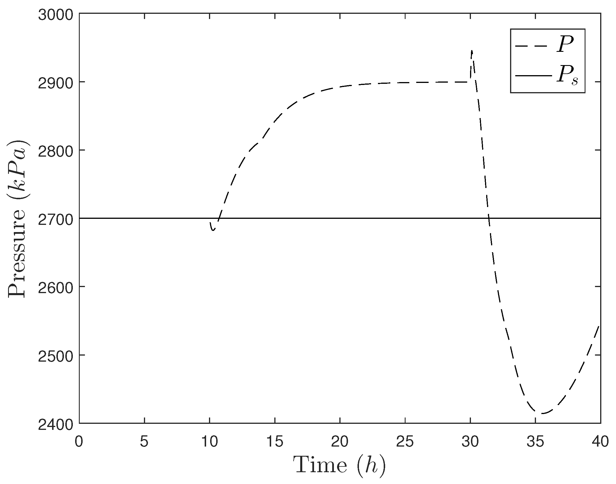
Figure 1. Pressure trajectory for the system of Equations (23)–(45) for a falsified y A 3 measurement set at 1 between 10 and 30 h of operation under proportional-integral (PI) control.
Mathematics 06 00169 g001
Figure 2. State-space trajectory showing the state trajectory in 10 sampling periods with the falsified state measurements determined through optimization applied at every sampling time, in the absence of disturbances.
Mathematics 06 00169 g002
Figure 3. Intersecting stability regions with two different potential initial conditions x ( t k ) = x a and x ( t k ) = x b .
Mathematics 06 00169 g003
Figure 4. State trajectories under the single Lyapunov-based model predictive controller (LMPC) for the CSTR of Equations (46) and (47).
Mathematics 06 00169 g004
Figure 5. Input trajectories under the single LMPC for the CSTR of Equations (46) and (47).
Mathematics 06 00169 g005
Figure 6. State-space trajectories under the single LMPC for the CSTR of Equations (46) and (47). The figure indicates that the closed-loop trajectory settled on the boundary of Ω ρ e , 1 to optimize the objective function while meeting the constraints. For simplicity, only one level set for each of the n p potential LMPC’s is shown ( Ω ρ i is shown if V i V 1 , and Ω ρ e , i is shown if V i = V 1 , i > 1 ).
Mathematics 06 00169 g006
Figure 7. State trajectories under the randomized LMPC implementation strategy for the CSTR of Equations (46) and (47).
Mathematics 06 00169 g007
Figure 8. Input trajectories under the randomized LMPC implementation strategy for the CSTR of Equations (46) and (47).
Mathematics 06 00169 g008
Figure 9. State-space trajectories under the randomized LMPC implementation strategy for the CSTR of Equations (46) and (47). For simplicity, only one level set for each of the n p potential LMPC’s is shown ( Ω ρ i is shown if V i V 1 , and Ω ρ e , i is shown if V i = V 1 , i > 1 ).
Mathematics 06 00169 g009
Figure 10. Scatter plot showing the control law chosen (i in Table 3) in each sampling period by the randomized LMPC implementation strategy.
Mathematics 06 00169 g010
Figure 11. State-space trajectories for all of the situations in Table 4. The numbers in the caption represent the seed values for rng. ‘S’ represents the single LMPC.
Mathematics 06 00169 g011
Figure 12. Trajectories of u 1 , u 2 , and V 1 under the randomized LMPC implementation strategy for rng(20) (denoted by ‘Randomized’ in the figure) and under the single LMPC (denoted by ‘Single’ in the figure). The value of ρ 1 is denoted by the horizontal line in the plot for the value of V 1 . The bottom plot indicates the controller selected by the randomized LMPC implementation strategy at each of the 10 sampling times in the simulation.
Mathematics 06 00169 g012
Table 1. Steady-state values for the states of the Tennessee Eastman Process [78].
ParameterValueUnit
N A , s 44.49999958429348kmol
N B , s 13.53296996509594kmol
N C , s 36.64788062995841kmol
N D , s 110.0kmol
X 1 , s 60.95327313484253%
X 2 , s 25.02232231706676%
X 3 , s 39.25777017606444%
X 4 , s 47.03024823457651%
u 1 , s 60.95327313484253%
u 2 , s 25.02232231706676%
u 3 , s 39.25777017606444%
V % , s p 44.17670682730923%
F 1 , s 201.43kmol/h
F 2 , s 5.62kmol/h
F 3 , s 7.05kmol/h
F 4 , s 100kmol/h
P s 2700kPa
y A 3 , s 0.47-
y B 3 , s 0.1429-
y C 3 , s 0.3871-
K c , 1 0.1% h/kmol
τ I , 1 1h
K c , 2 2%
τ I , 2 3h
K c , 3 –0.25%/kPa
τ I , 3 1.5h
K c , 4 0.7kmol/kPa·h
τ I , 4 3h
Table 2. Parameters for the continuous stirred tank reactor (CSTR) process.
ParameterValueUnit
V1m 3
T 0 300K
  C p 0 . 231 kJ/kg·K
  k 0 8 . 46 × 10 6 m 3 /h·kmol
  F5m 3 /h
  ρ L 1000kg/m 3
  E 5 × 10 4 kJ/kmol
  R g 8 . 314 kJ/kmol·K
  Δ H 1 . 15 × 10 4 kJ/kmol
Table 3. i-th controller parameters.
i P 11 P 12 P 22 ρ i ρ e , i
1120050.1180144
22000–201180144
31500–2010180144
40.202000180144
5120050.1180100
6120050.1180130
7120050.118030
Table 4. Approximate time after which x 2 > 55 K for various seed values of rng for the randomized LMPC design subjected to a cyberattack on the sensors determined in Section 5.2.1.
SeedTime x 2 > 55 K (h)
50.0143
100.0148
150.0146
200.0324
250.0146
300.0142
350.0143
400.0147
450.0248
500.0231
Table 5. Approximate time after which x 2 > 55 K for various seed values of rng for the randomized LMPC design subjected to a cyberattack on the sensors with x 1 = 0 . 0632 kmol/m 3 and x 2 = 21 . 2056 K .
SeedTime x 2 > 55 K (h)
50.0674
100.0458
150.0555
200.0767
250.0569
300.0418
350.0457
400.0874
450.0580
500.0950