Article

Differential Quadrature Method for Bending Analysis of Asymmetric Circular Organic Solar Cells Resting on Kerr Foundation in Hygrothermal Environment

Department of Mathematics and Statistics, College of Science, King Faisal University, P.O. Box 400, Al-Ahsa 31982, Saudi Arabia
*
Author to whom correspondence should be addressed.
Mathematics 2025, 13(7), 1203; https://doi.org/10.3390/math13071203
Submission received: 26 February 2025 / Revised: 25 March 2025 / Accepted: 4 April 2025 / Published: 6 April 2025

Abstract

:
This article presents the first theoretical analysis of the bending behavior of circular organic solar cells (COSCs). The solar cell under investigation is built on a flexible Kerr foundation and has five layers of Al, P3HT:PCBM, PEDOT:PSS, ITO, and Glass. The cell is exposed to hygrothermal conditions. The related Kerr foundation lessens displacements and supports the cell. The principle of virtual work is used to generate the basic partial differential equations, which are then solved using the differential quadrature method (DQM). The results of the present theory are validated by comparing them with published ones. The effects of the temperature, humidity, elastic foundation factors, and geometric configuration characteristics on the deflection and stresses of the COSC are examined.

1. Introduction

With the advancement of technology, one of the issues that most concern scientists these days is energy. Fossil fuels are widely used in the world, yet they have a number of drawbacks. The main one is that they may run out and contaminate the environment, in addition to causing global warming. Among the greatest substitutes for fossil fuels are natural energy sources. Indeed, solar energy is one of the most significant and fascinating natural energy resources. The usage of solar energy, which is clean, sustainable, and renewable, is what distinguishes them from other types of devices [1,2,3]. However, because of the high manufacturing costs of the conventional solar cells, scientists are now interested in producing organic solar cells (OSC), which have substantially reduced the manufacturing costs [4,5]. The thinness, lightweight, and flexibility of organic solar cells are further characteristics that set them apart. Numerous technological sectors have made use of these organic solar cells [6,7,8]. To boost their production, researchers investigate organic solar cells in a variety of conditions. For example, Li and associates investigated the bending and buckling of organic solar cells resting on Winkler-Pasternak elastic basis [9,10]. Moreover, Duc et al. [11] investigated the nonlinear behavior and vibration properties of organic solar cells (OSC) exposed to transverse dynamic loading in conjunction with in-plane compressive stresses using the classical plate theory (CPT). Dat and associates utilized the Bees Algorithm to enhance the organic solar cells bending loads [12]. Li and colleagues examined how temperature and flexible foundations affect the dynamic mobility of organic solar cells [13].
For a number of years, scientists have been closely monitoring the investigation of structures placed above the foundations. Several theories for foundation models have been developed to represent the link between the plate and foundation [14,15]. With only one coefficient substrate response, the Winkler elastic foundation [16] is the oldest and most fundamental theory of elastic media models. Even though the Winkler type is easy to install, its separate springs make it challenging to maintain continuity in the foundation [17]. By adding a shear layer to the springs, the Pasternak model [18] improved this hypothesis. The Pasternak model, which takes into account a two-parameter substrate (shear layer and spring), is frequently used to explain the mechanical interactions of soft plates with different distributions of material properties. The Pasternak model was expanded in 1964 by Kerr [19], who included a spring layer above the shearing layer. This was done because the free edges of a structure experience strong reactions when the Pasternak model is applied. This suggests that the base of the Kerr model is a three-parameter elastic model consisting of an independent top layer, a shear layer, and a bottom layer that is roughly represented by scattered springs. The organic solar cells are very thin, so placing one of the aforementioned three types of flexible foundation under them makes them stronger and less susceptible to bending installation or due to humidity. This placing reduces pressure and displacement resulting from moisture and heat [10]. The Kerr model gives more stability to organic solar cells than the other two models.
In this research, we intend to investigate the bending of a circular organic solar cell consisting of five layers as follows: Al, P3HT:PCBM, PEDOT:PSS, IOT and glass. The cell is based on a flexible foundation under hygrothermal conditions. Due to the difficulties of solving the governing differential equations analytically, the differential quadrature technique will be used to simplify and solve them numerically. It is anticipated that Kerr foundation will stabilize the cell and reduce its displacement. We will also examine how the deflection, normal stress, in-plane shear stress, and transverse shear stress of organic solar cells are affected by the temperature, humidity, elastic foundation parameters, and geometric form characteristics. This provides more insight into producing a more stable cell. The novelty of the present work can be summarized as follows: (a) This work presents the first theoretical investigation of the bending response of circular organic solar cells (COSCs), filling a gap in the existing literature. (b) Unlike previous studies, we incorporate the impact of both moisture and temperature variations on the bending behavior of COSCs, providing a more comprehensive analysis. (c) A novel four-variable shear deformation theory is introduced to describe the displacement field. (d) The study considers a Kerr foundation as a flexible substrate, which better represents the real-world mechanical support of COSCs compared to conventional foundation models.

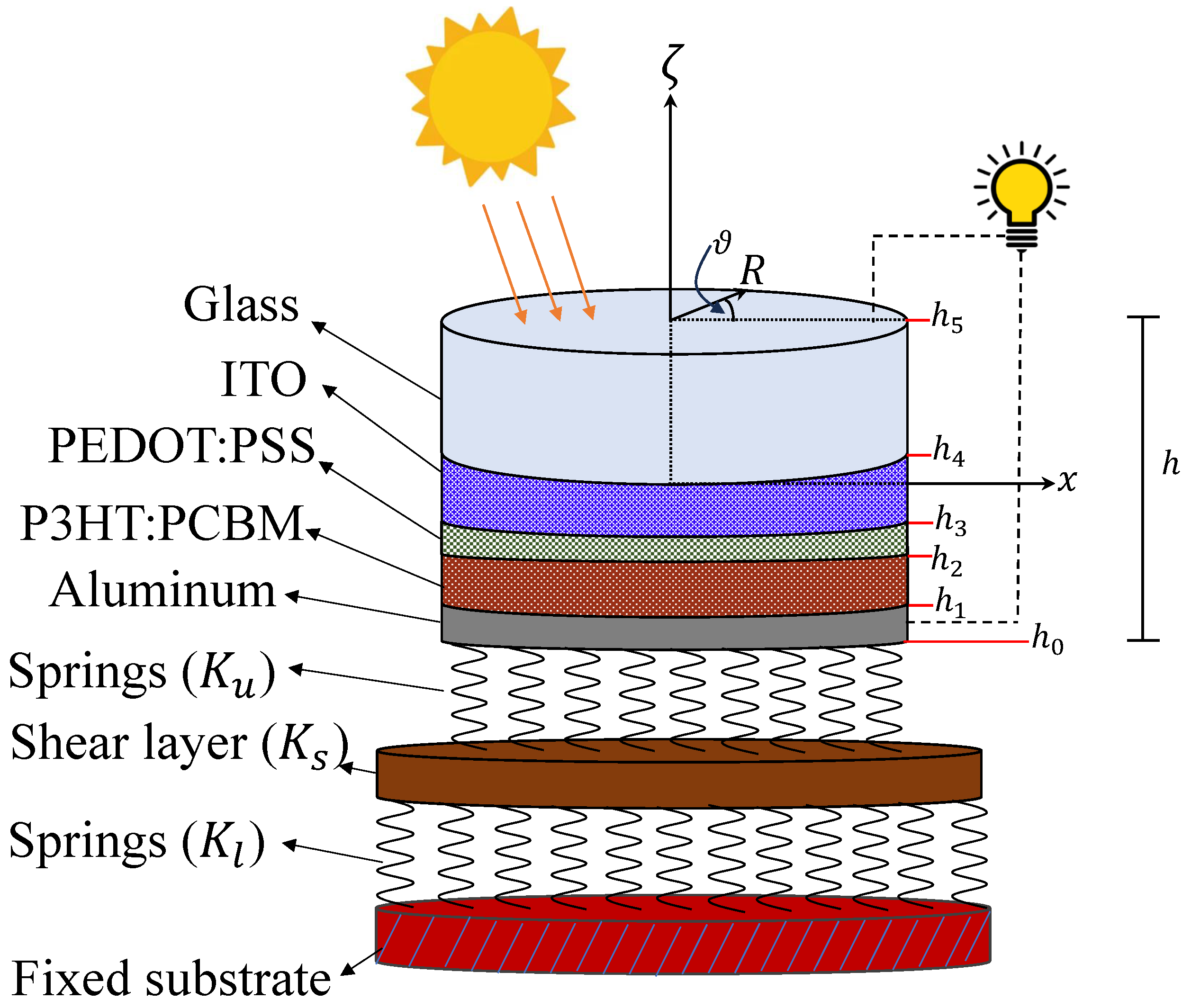
2. Formulation of the Problem

Five separate material layers: Al, P3HT:PCBM, PEDOT:PSS, ITO, and Glass, each has the same radius a and total thickness h, make up the inquiry model utilized in this study. The different layers of the COSC are assumed to be perfectly bonded. This assumption ensures continuity of displacements and stresses across the layers, meaning there is no relative sliding or separation at the interfaces. Furthermore, the cells are supported by the Kerr elastic foundations as shown in Figure 1.

2.1. Displacement Field

Shimpi’s plate theory has been constructed in the Cartesian coordinate system on the basis of certain suppositions [20]. These assumptions are obviously appropriate for application in the circular coordinate system ( R , ϑ , ζ ) , which can be defined as:
  • The transverse normal stress τ 3 is negligible when compared to the in-plane stresses τ 1 and τ 2 .
  • The strains involved are very small due to the minimal displacements.
  • The lateral displacement u 3 consists of two components: the shear component u b and the bending component u s .
  • The in-plane displacements have two components: (a) The bending components u 1 b and u 2 b are analogous to the displacements u 1 and u 2 in classical plate theory. Their expressions are given by
    u 1 b = ζ u b R , u 2 b = ζ R u b ϑ .
    (b) The shear components u 1 s and u 2 s of the displacements u 1 and u 2 , in terms of u s , induce parabolic variations in the shear stresses τ 13 and τ 23 across the plate’s cross-section. These shear stresses are zero at the top and bottom surfaces of the plate, i.e., at ζ = h / 2 and ζ = h / 2 .
Accordingly, the components of the displacement field ( u 1 , u 2 , u 3 ) are given as:
u 1 ( R , ϑ , ζ ) = ζ u b R g ( ζ ) u s R , u 2 ( R , ϑ , ζ ) = ζ R u b ϑ g ( ζ ) R u s ϑ , u 3 ( R , ϑ ) = u b ( R , ϑ ) + u s ( R , ϑ ) ,
when g ( ζ ) = ζ g ^ ( ζ ) and
g ^ ( ζ ) = h 2 sinh 1 ( 2 ζ h ) 2 2 3 h 2 ζ 3 , h 2 < ζ < h 2 .
The function g ^ ( ζ ) has been defined as follows in the literature [21,22,23,24]:
g ^ ( ζ ) = ζ ( 1 4 ζ 2 3 h 2 ) , Third - order plate theory ( TDPT ) , g ^ ( ζ ) = h π sin ( π ζ h ) , Sinusoidal plate theory ( SDPT ) , g ^ ( ζ ) = h sinh ( ζ h ) ζ cosh ( 1 2 ) , Hyperbolic plate theory ( HDPT ) , g ^ ( ζ ) = ζ exp ( 2 ζ 2 h 2 ) , Exponential plate theory ( EDPT ) .
Note that the classical plate theory can be obtained by taking g ^ ( ζ ) = 0 .

2.2. Hygrothermal Field

Structures are frequently subjected to high temperatures and moisture levels during production or usage. As predicted, these circumstances make the structures weaker, which has an impact on their behavior and stability [25,26,27]. The temperature field T ( R , ϑ , ζ ) and moisture concentration C ( R , ϑ , ζ ) are assumed to be applied to the current circular solar cell and are provided as [28]:
T ( R , ϑ , ζ ) = T ^ ( ζ ) sin ( λ R ) sin ( p n ϑ ) , C ( R , ϑ , ζ ) = C ^ ( ζ ) sin ( λ R ) sin ( p n ϑ ) ,
where T ^ ( ζ ) and C ^ ( ζ ) are the temperature and moisture distributions throughout the thickness of the plate, and λ = π a , p n = 1 , 2 , . Temperature and moisture are assumed to vary sinusoidally in the radial and circumferential directions, as shown by (5). However, they are given in the direction of thickness by the solution of the one-dimensional moisture diffusion and heat conduction equations, which are given as follows [28]:
d d ζ K d T ^ ( ζ ) d ζ = 0 , T ( h 2 ) = T 0 , T ( h 2 ) = T u , d d ζ K ¯ d C ^ ( ζ ) d ζ = 0 , C ( h 2 ) = C 0 , C ( h 2 ) = C u ,
where T 0 and C 0 stand for the corresponding reference points for temperature and moisture, respectively. On the other hand, T u and C u represent the plate’s top surface temperature and moisture content, respectively. The coefficients of moisture diffusivity is K ¯ and thermal conductivity is K. By solving Equation (6), one gets:
T ^ ( ζ ) = T 0 + Δ T ζ h + 1 2 , Δ T = T u T 0 , C ^ ( ζ ) = C 0 + Δ C ζ h + 1 2 , Δ C = C u C 0 .

2.3. Kerr Foundation

In 1964, Kerr [19] presented an extension of the Pasternak model by adding a spring layer on top of the shearing layer. This was done since the Pasternak model causes intense responses around a structure’s free edges. This indicates that the Kerr model foundation is the most practical one with three-parameter elastic model made up of a bottom layer approximated by distributed springs (with stiffness K l ), an independent upper layer (with stiffness K u ), and a shear layer (with stiffness K s ). It should be noted that, if the shear modulus K s is equal to zero, the Winkler model may be viewed as a specific instance of the Pasternak model. Degrading the Kerr model to the Pasternak model is also possible by omitting the upper springs. The following is the definition of the Kerr foundation model’s distributed reaction [29]:
q K e r r = K l K u K l + K u u b + u s K s K u K l + K u 2 u b + u s .

2.4. Strain and Stress Field Relations

The following formula is used to compute the strain field in the cylindrical coordinate:
ε 1 = u 1 R = ζ 2 u b R 2 g ( ζ ) 2 u s R 2 , ε 2 = 1 R u 2 ϑ + u 1 = ζ R u b R + 1 R 2 u b ϑ 2 g ( ζ ) R u s R + 1 R 2 u s ϑ 2 , ε 3 = u 3 ζ = 0 , γ 12 = u 2 R + u 1 R ϑ u 2 R = 1 R 2 ζ R u b ϑ + 2 g ( ζ ) R u s ϑ 2 ζ 2 u b ϑ R 2 g ( ζ ) 2 u s ϑ R , γ 13 = u 1 ζ + u 2 R = g ^ ( ζ ) u s R , g ^ ( ζ ) = g ^ ( ζ ) ζ , γ 23 = u 2 ζ + u 3 R ϑ = g ^ ( ζ ) u s R ϑ ,
where ε 12 = 1 2 γ 12 , ε 13 = 1 2 γ 13 and ε 23 = 1 2 γ 23 are the shear strains and ε 1 and ε 2 are normal strains.
Furthermore, constitutive equations accounting for hygrothermal loads may be used to represent the stresses for a circular elastic plate as follows:
τ 1 ( n ) = E ( n ) ( 1 [ ν ( n ) ] 2 ) [ ε 1 + ν ( n ) ε 2 ( 1 + ν ( n ) ) Λ ( n ) T ( 1 + ν ( n ) ) Υ ( n ) C ] , τ 2 ( n ) = E ( n ) ( 1 [ ν ( n ) ] 2 ) [ ε 2 + ν ( n ) ε 1 ( 1 + ν ( n ) ) Λ ( n ) T ( 1 + ν ( n ) ) Υ ( n ) C ] , τ 3 ( n ) = 0 , τ 12 ( n ) = E ( n ) 1 + ν ( n ) ε 12 , τ 13 ( n ) = E ( n ) 1 + ν ( n ) ε 13 , τ 23 ( n ) = E ( n ) 1 + ν ( n ) ε 23 , n = 1 , 2 , , 5 ,
where Λ ( n ) indicates the cofficient of thermal expansion, Υ ( n ) indicates the cofficient of moisture expansion; E ( n ) and ν ( n ) are the plate nth layer Young’s modulus and Poisson’s ratios, respectively.

3. Governing Equations

The governing differential equations are derived using the principle of virtual work [30]:
δ S δ W k = 0 ,
where δ S is the variation of strain energy and δ W k is the variation of the work brought on the external load and the Kerr foundation. These are given by:
δ S = n = 1 5 0 2 π 0 a h n 1 h n ( τ 1 ( n ) δ ε 1 + τ 2 ( n ) δ ε 2 + 2 τ 12 ( n ) δ ε 12 + 2 τ 13 ( n ) δ ε 13 + 2 τ 23 ( n ) δ ε 23 ) R d ζ d R d ϑ ,
δ W k = 0 2 π 0 a ( q e x q K e r r ) δ u 3 R d R d ϑ ,
where h 0 = h / 2 , h 5 = h / 2 , ( h 1 , h 2 , h 3 , h 4 ) are the coordinates among the strata. Additionally, q e x is the external vertical load. By inserting Equations (12) and (13) into Equation (11), the governing equations are obtained as:
δ u b : 2 R N 1 R + 2 N 1 R 2 N 2 R R + 1 R 2 2 N 2 ϑ 2 + 2 R 2 N 12 ϑ + 2 R 2 N 12 ϑ R + q e x q K e r r = 0 , δ u s : 2 R M 1 R + 2 M 1 R 2 1 R M 2 R + 1 R 2 2 M 2 ϑ 2 + 2 R 2 M 12 ϑ + 2 R 2 M 12 ϑ R + M 13 R + M 13 R + 1 R M 23 ϑ + q e x q K e r r = 0 ,
where
{ N 1 , N 2 , N 12 } = n = 1 5 h n 1 h n τ 1 ( n ) , τ 2 ( n ) , τ 12 ( n ) ζ d ζ , { M 1 , M 2 , M 12 } = n = 1 5 h n 1 h n τ 1 ( n ) , τ 2 ( n ) , τ 12 ( n ) g ( ζ ) d ζ , { M 13 , M 23 } = n = 1 5 h n 1 h n τ 13 ( n ) , τ 23 ( n ) g ^ ( ζ ) d ζ .
With the help of Equation (9), we can insert Equation (10) into Equation (15) to get:
N 1 = L 1 2 u b R 2 L 2 2 u s R 2 L 1 ¯ R u b R + 1 R 2 u b ϑ 2 L 2 ¯ R u s R + 1 R 2 u s ϑ 2 + ( L T + L C ) sin ( λ R ) sin ( p n ϑ ) , N 2 = L 1 R u b R + 1 R 2 u b ϑ 2 L 2 R u s R + 1 R 2 u s ϑ 2 L 1 ¯ 2 u b R 2 L 2 ¯ 2 u s R 2 + ( L T + L C ) sin ( λ R ) sin ( p n ϑ ) , N 12 = L 7 R 2 u b ϑ + L 8 R 2 u s ϑ L 7 R 2 u b ϑ R L 8 R 2 u s ϑ R ,
M 13 = L 6 u s R , M 23 = L 6 R u s ϑ , M 1 = L 2 2 u b R 2 L 4 2 u s R 2 L 2 ¯ R u b R + 1 R 2 u b ϑ 2 L 4 ¯ R u s R + 1 R 2 u s ϑ 2 + ( M T + M C ) sin ( λ R ) sin ( p n ϑ ) , M 2 = L 2 R u b R + 1 R 2 u b ϑ 2 L 4 R u s R + 1 R 2 u s ϑ 2 L 2 ¯ 2 u b R 2 L 4 ¯ 2 u s R 2 + ( M T + M C ) sin ( λ R ) sin ( p n ϑ ) , M 12 = L 8 R 2 u b ϑ + L 9 R 2 u s ϑ L 8 R 2 u b ϑ R L 9 R 2 u s ϑ R ,
in which
{ L 1 , L 2 , L 4 } = n = 1 5 h n 1 h n E ( n ) 1 [ ν ( n ) ] 2 { ζ 2 , ζ g ( ζ ) , g 2 ( ζ ) } d ζ , { L 1 ¯ , L 2 ¯ , L 4 ¯ } = n = 1 5 h n 1 h n ν ( n ) E ( n ) 1 [ ν ( n ) ] 2 { ζ 2 , ζ g ( ζ ) , g 2 ( ζ ) } d ζ , { L T , M T } = n = 1 5 h n 1 h n E ( n ) 1 ν ( n ) Λ ( n ) T ^ ( ζ ) { ζ , g ( ζ ) } d ζ , { L C , M C } = n = 1 5 h n 1 h n E ( n ) 1 ν ( n ) Υ ( n ) C ^ ( ζ ) { ζ , g ( ζ ) } d ζ , { L 6 , L 7 , L 8 , L 9 } = n = 1 5 h n 1 h n E ( n ) 2 1 + ν ( n ) [ g ^ ( ζ ) ] 2 , 2 ζ 2 , 2 ζ g ( ζ ) , 2 g 2 ( ζ ) d ζ .
By inserting Equations (16) and (17) into Equation (14), one determines the governing Equation (14) in terms of the displacement components as follows:
L 1 4 u b R 4 L 2 4 u s R 4 L 1 R 4 4 u b ϑ 4 L 2 R 4 4 u s ϑ 4 + 2 L 7 2 L 1 ¯ R 2 4 u b R 2 ϑ 2 + 2 L 8 2 L 2 ¯ R 2 4 u s R 2 ϑ 2 2 L 1 R 3 u b R 3 2 L 2 R 3 u s R 3 + 2 L 7 6 L 1 ¯ R 3 3 u b R ϑ 2 + 2 L 8 6 L 2 ¯ R 3 3 u s R ϑ 2 + L 1 4 L 1 ¯ R 2 + K s k u K l + K u 2 u b R 2 + L 2 4 L 2 ¯ R 2 + K s k u K l + K u 2 u s R 2 + 2 L 1 2 L 1 ¯ 2 L 7 R 4 + K s k u K l + K u R 2 2 u b ϑ 2 + 2 L 2 2 L 2 ¯ 2 L 8 R 4 + K s k u K l + K u R 2 2 u s ϑ 2 + L 1 R 3 + K s k u K l + K u R u b R + L 2 R 3 + K s k u K l + K u R u s R + K s k u K l K u K l + K u u b + K s k u K l K u K l + K u u s + ( L T + L C ) λ R cos ( λ R ) sin ( p n ϑ ) ( L T + L C ) λ 2 + P n 2 R 2 sin ( λ R ) sin ( p n ϑ ) + q e x = 0 ,
L 2 4 u b R 4 L 4 4 u s R 4 L 2 R 4 4 u b ϑ 4 L 4 R 4 4 u s ϑ 4 + 2 L 8 2 L 2 ¯ R 2 4 u b R 2 ϑ 2 + 2 L 9 2 L 4 ¯ R 2 4 u s R 2 ϑ 2 2 L 2 R 3 u b R 3 2 L 4 R 3 u s R 3 + 2 L 8 6 L 2 ¯ R 3 3 u b R ϑ 2 + 2 L 9 6 L 4 ¯ R 3 3 u s R ϑ 2 + L 2 4 L 2 ¯ R 2 + K s k u K l + K u 2 u b R 2 + L 4 4 L 4 ¯ R 2 + K s k u K l + K u + L 6 2 2 u s R 2 + 2 L 2 2 L 2 ¯ 2 L 8 R 4 + K s k u K l + K u R 2 2 u b ϑ 2 + 2 L 4 2 L 4 ¯ 2 L 9 R 4 + K s k u K l + K u R 2 + L 6 2 R 2 u s ϑ 2 + L 2 R 3 + K s k u K l + K u R u b R + L 4 R 3 + K s k u K l + K u + L 6 2 R u s R + K s k u K l K u K l + K u u b + K s k u K l K u K l + K u u s + ( M T + M C ) λ R cos ( λ R ) sin ( p n ϑ ) ( M T + M C ) λ 2 + P n 2 R 2 sin ( λ R ) sin ( p n ϑ ) + q e x = 0 .
It is presumed that the following trigonometric Fourier series represent the displacements of the circular plate [31]. The displacements are therefore provided as:
u b = n = 1 V b ( R ) sin p n ϑ , u s = n = 1 V s ( R ) sin p n ϑ , q e x = n = 1 q 0 sin λ R sin p n ϑ ,
where q 0 is the cell center’s load intensity, p n = 1 , 2 , 3 , . and V b ( R ) and V s ( R ) are functions of R. The displacements (21) are then substituted into Equations (19) and (20) to provide the governing equations as:
A 1 d 4 V b ( R ) d R 4 + A 2 d 4 V s ( R ) d R 4 + A 3 R d 3 V b ( R ) d R 3 + A 4 R d 3 V s ( R ) d R 3 + A 5 + A 6 R 2 d 2 V b ( R ) d R 2 + A 5 + A 7 R 2 d 2 V s ( R ) d R 2 + A 5 R A 6 R 3 d V b ( R ) d R + A 5 R A 7 R 3 d V s ( R ) d R + A 8 + A 9 R 2 + A 10 R 4 V b ( R ) + A 8 + A 9 R 2 + A 11 R 4 V s ( R ) + A 12 cos ( λ R ) R + A 13 sin ( λ R ) + A 14 sin ( λ R ) p n 2 R 2 + q 0 sin ( λ R ) = 0 ,
B 1 d 4 V b ( R ) d R 4 + B 2 d 4 V s ( R ) d R 4 + B 3 R d 3 V b ( R ) d R 3 + B 4 R d 3 V s ( R ) d R 3 + B 5 + B 6 R 2 d 2 V b ( R ) d R 2 + B 7 + B 8 R 2 d 2 V s ( R ) d R 2 + B 5 R B 6 R 3 d V b ( R ) d R + B 7 R B 8 R 3 d V s ( R ) d R + B 9 + B 10 R 2 + B 11 R 4 V b ( R ) + B 9 + B 12 R 2 + B 13 R 4 V s ( R ) + B 14 cos ( λ R ) R + B 15 sin ( λ R ) + B 16 sin ( λ R ) p n 2 R 2 + q 0 sin ( λ R ) = 0 ,
in which
{ A 1 , A 2 , A 3 , A 4 } = { L 1 , L 2 , 2 A 1 , 2 A 2 } , { B 1 , B 2 , B 3 , B 3 } = { A 2 , L 4 , A 4 , 2 B 2 } , A 5 = K s K u K l + K u , B 5 = A 5 , A 6 = 2 L 7 p n 2 + 2 L 1 ¯ p n 2 + L 1 , B 6 = A 7 , A 7 = 2 L 8 p n 2 + 2 L 2 ¯ p n 2 + L 2 , B 7 = L 6 + B 5 , A 8 = K l K u K l + K u , B 8 = 2 L 9 p n 2 + 2 L 4 ¯ p n 2 + L 4 , A 9 = K s K u K l + K u p n 2 , B 9 = A 8 , A 10 = L 2 p n 4 + 2 L 2 ¯ p n 2 + 2 L 8 p n 2 + 2 L 2 p n 2 , B 10 = A 9 , A 11 = L 2 p n 4 + 2 L 2 ¯ p n 2 + 2 L 8 p n 2 + 2 L 2 p n 2 , B 11 = A 11 , A 12 = ( L T + L C ) λ , B 12 = L 6 p n 2 + B 10 , A 13 = λ A 12 , B 13 = L 4 p n 4 + 2 L 4 ¯ p n 2 + 2 L 9 p n 2 + 2 L 4 p n 2 , A 14 = ( L T + L C ) , B 14 = ( M T + M C ) , B 15 = λ 2 B 14 , B 16 = ( M T + M C ) .
It is assumed that the organic solar cell’s edge ( R = a ) is clamped in the current investigation. Thus, we have
V b = V s = 0 .
Furthermore, the following conditions are displayed in the solid circular cell’s center ( R = 0 ) [31,32]:
d V b d R = d V s d R = 0 .

4. Solution Methods

The Equations (22) and (23) are solved using the DQM [33,34], which is applied in the radial direction. The DQM has been widely utilized to solve the governing equations of various structures [28,35,36,37]. This is because, in comparison to other numerical approaches, it offers straightforward formulas and involves less computing work. The present COSC is discretized by m mesh circles with radius R [ 0 , a ] . According to the DQM, the displacement derivatives are approximately given as a weighted linear sum of function values at each circle as [38]:
d y V b d R y R = R i = j = 1 m D i j ( y ) V j b , d y V s d R y R = R i = j = 1 m D i j ( y ) V j s , i = 1 , 2 , , m ,
where D i j ( y ) represent the weighting coefficients for the yth-order derivative, and V i b = V b ( R i ) and V i s = V s ( R i ) . The supplied values are [38]:
D i j ( 1 ) = X ( R i ) ( R i R j ) X ( R j ) , i , j = 1 , 2 , , m , i j , D i i ( 1 ) = i = 1 m D l i ( 1 ) , i = 1 , 2 , , m , i l , X ( R i ) = i = 1 m ( R i R j ) , i j .
Additionally, the following formula is used to obtain the weighting factors D i j ( y ) ( y > 1 ) for the higher order derivatives [38]:
D i j ( y ) = l = 1 m D i l ( 1 ) D l j ( y 1 ) , i , j = 1 , 2 , , m .
Furthermore, the Gauss-Chebyshev-Lobatto technique has been utilized to estimate the mesh points R i , as stated in [38]:
R i = a 2 1 cos π i 1 m 1 .
Using Equation (27) in conjunction with Equations (22) and (23) allows for the discretization of the governing equations as follows:
A 1 j = 1 m D i j ( 4 ) V j b + A 2 j = 1 m D i j ( 4 ) V j s + A 3 R i j = 1 m D i j ( 3 ) V j b + A 4 R i j = 1 m D i j ( 3 ) V j s + A 5 + A 6 R i 2 j = 1 m D i j ( 2 ) V j b + A 5 + A 7 R i 2 j = 1 m D i j ( 2 ) V j s + A 5 R i A 6 R i 3 j = 1 m D i j ( 1 ) V j b + A 5 R i A 7 R i 3 j = 1 m D i j ( 1 ) V j s + A 8 + A 9 R i 2 + A 10 R i 4 V i b + A 8 + A 9 R i 2 + A 11 R i 4 V i s + A 12 cos ( λ R i ) R i + A 13 sin ( λ R i ) + A 14 sin ( λ R i ) p n 2 R i 2 + q 0 sin ( λ R i ) = 0 ,
B 1 j = 1 m D i j ( 4 ) V j b + B 2 j = 1 m D i j ( 4 ) V j s + B 3 R i j = 1 m D i j ( 3 ) V j b + B 4 R i j = 1 m D i j ( 3 ) V j s + B 5 + B 6 R i 2 j = 1 m D i j ( 2 ) V j b + B 7 + B 8 R i 2 j = 1 m D i j ( 2 ) V j s + B 5 R i B 6 R i 3 j = 1 m D i j ( 1 ) V j b + B 7 R i B 8 R i 3 j = 1 m D i j ( 1 ) V j s + B 9 + B 10 R i 2 + B 11 R i 4 V i b + B 9 + B 12 R i 2 + B 13 R i 4 V i s + B 14 cos ( λ R i ) R i + B 15 sin ( λ R i ) + B 16 sin ( λ R i ) p n 2 R i 2 + q 0 sin ( λ R i ) = 0 , i = 2 , 3 , , m 1 .
Furthermore, the boundary conditions are represented in the discretization form as:
V i b = V i s = 0 , i = m , j = 1 m D i j ( 1 ) V j b = j = 1 m D i j ( 1 ) V j s = 0 , i = 1 .
To get the deflection, one can solve Equations (31) and (32) with the boundary conditions (33).

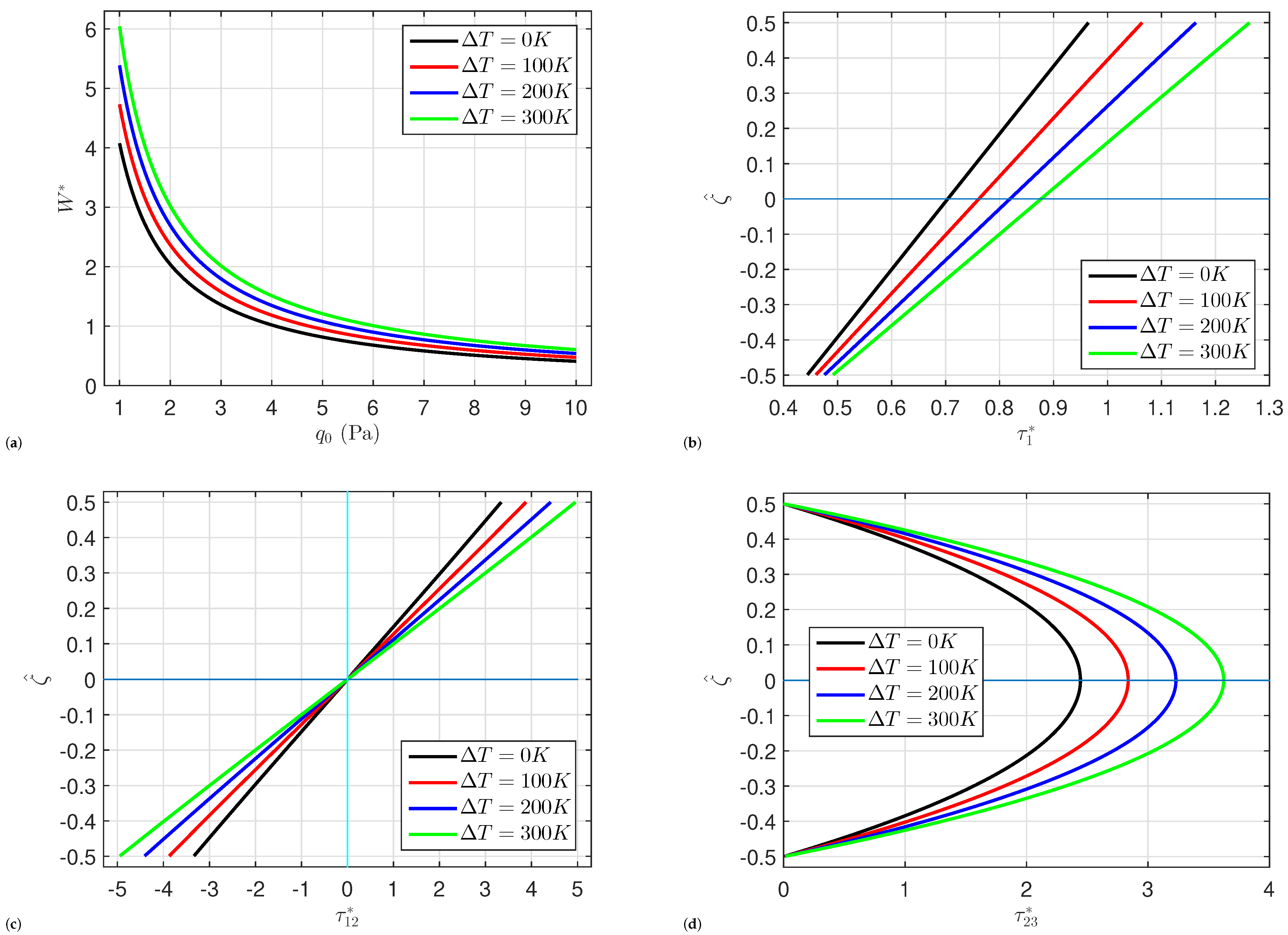
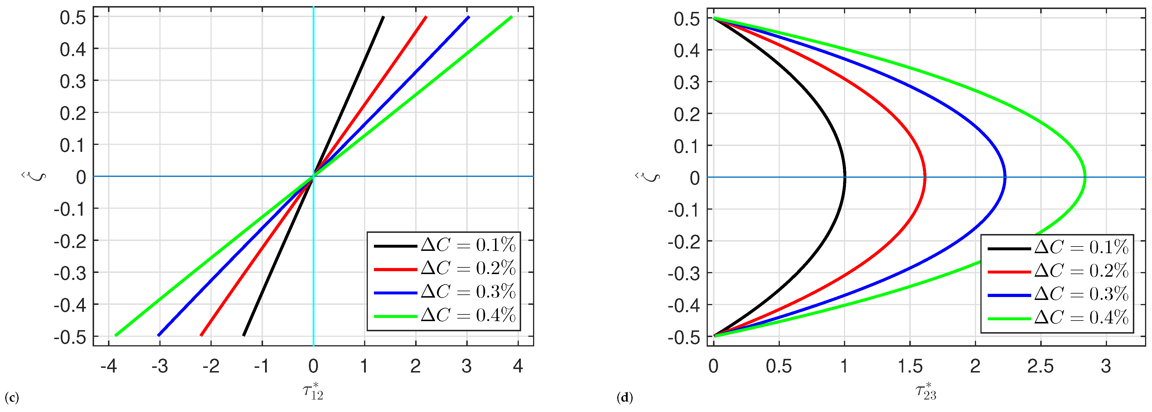
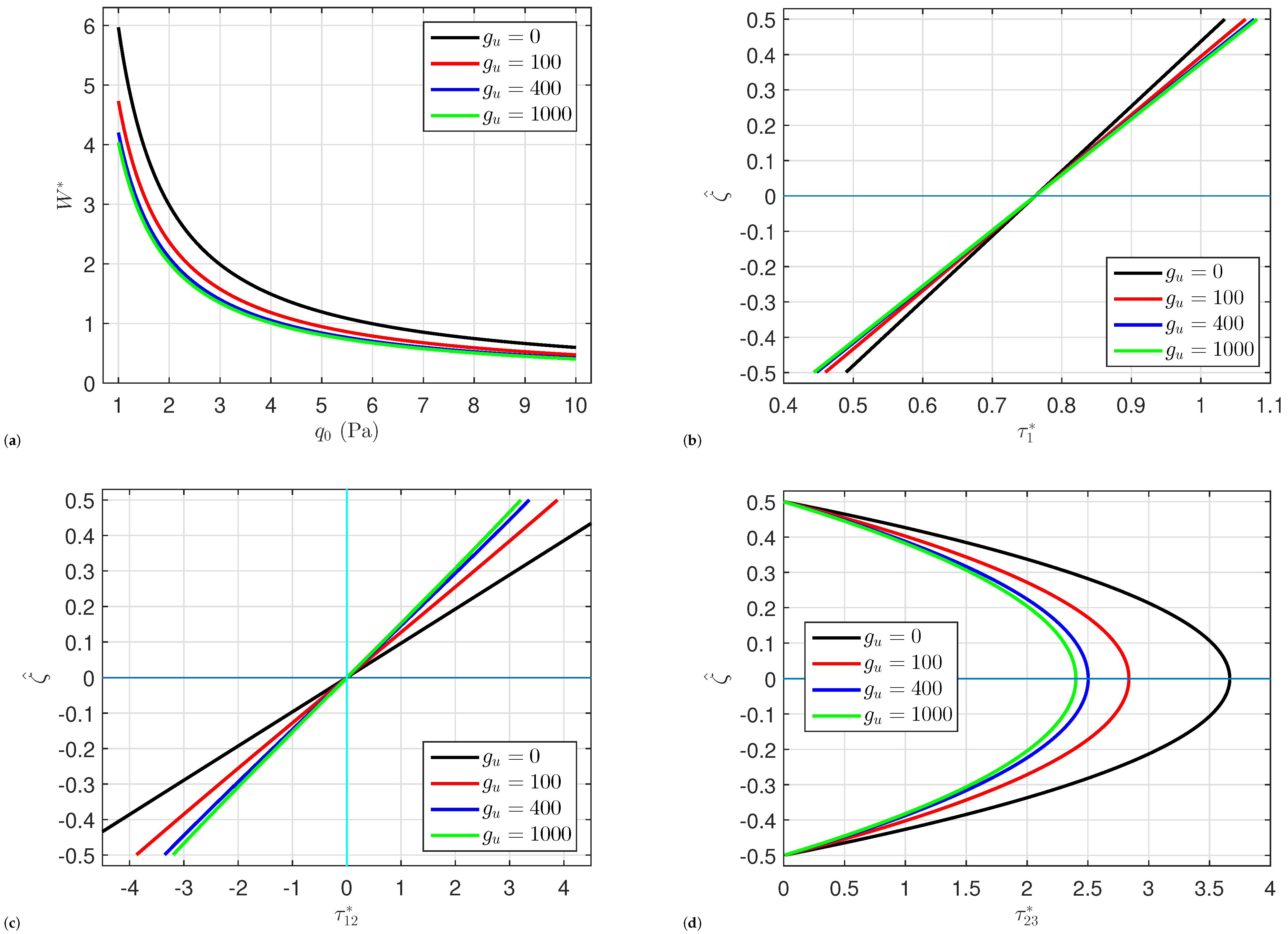
5. Numerical Results

In order to investigate how several parameters affect the bending of circular organic solar cells subjected to hygrothermal circumstances, many numerical examples are illustrated here. Except otherwise stated, the following data are used: C 0 = 0 % , Δ C = 0.4 % , T 0 = 300 K, Δ T = 100 K, P n = 1 , a / h = 10 , g s = 15 , g l = 100 , g u = 100 , q 0 = 10 Pa. Table 1 gives the thickness and characteristics of each layer. The present study uses of the subsequent dimensionless:
g u = a 4 K u D ( 1 ) , g l = a 4 K l D ( 1 ) , g s = a 2 K s D ( 1 ) , D ( 1 ) = h 3 E ( 1 ) 12 ( 1 [ ν ( 1 ) ] 2 ) , ζ ^ = ζ / h , τ 1 * = 10 3 E ( 1 ) q 0 τ 1 a 2 , π 2 , ζ , τ 12 * = 10 5 E ( 1 ) q 0 τ 12 a 2 , 0 , ζ , τ 23 * = 10 4 E ( 1 ) q 0 τ 23 a 2 , 0 , ζ , W * = 10 ( 5 ) E ( 1 ) q 0 u 3 a 2 , π 2 .
Finding the minimum of discrete points required for the convergent solution of the DQM is essential. Consequently, Table 2 displays a convergence study of the DQM for circular organic solar cells supported by Kerr foundations with different ratios of radius-to-thickness a / h . The results are shown to converge at around 13 grid points.
As shown in Table 3, the results of the central defection W * of FGM solid circular plate with simply supported condition are compared with those published by Sobhy [37], Reddy et al. [39], and Yun et al. [40]. The purpose of this comparison is to confirm that the current formulas are accurate. The elastic modulus is calculated as follows:
E ( ζ ) = E c + ( E m E c ) 1 2 ζ h k .
The findings are derived for various values of the thickness-to-radius ratio h / a and power law index k. Moreover, it is evident that the central deflection W * rises as the thickness-to-radius ratio h / a increases. Furthermore, it should be mentioned that the central deflection W * decreases as the k value increases because the ceramic components increases as the index k increases. For all values of both the parameter k and the ratio h / a , our current results are in good agreement with those reported in the literature.
Figure 2 shows how the radius-to-thickness ratio a / h affects the central deflection W * , normal stress τ 1 * , in-plane shear stress τ 12 * , and transverse shear stress τ 23 * of the organic solar cells. Since the organic cells become thinner with increasing the ratio a / h , the deflection W * and the transverse shear stress τ 23 * are increased by the increment in the radius-to-thickness ratio a / h . By contrast, the normal stress τ 1 * and the in-plane shear stresses τ 12 * are weakly affected by changing the radius-to-thickness ratio a / h .
The effects of the temperature change Δ T and the moisture change Δ C on the organic solar cells’ central deflection W * , normal stress τ 1 * , transverse shear stress τ 23 * , and in-plane shear stress τ 12 * are shown in Figure 3 and Figure 4, respectively. The deflection and stresses grow monotonically when the temperature and moisture changes Δ T and Δ C increase. This is because rising temperature and moisture weakens the structures. Additionally, the transverse shear stresses at the plate’s top and bottom surfaces are equal to zero. While, the maximum is occurs at the plate’s midplane.
The effects of the shear layer stiffness g s , upper spring stiffness g u , and lower spring stiffness g l on the behavior of the organic solar cells including the deflection W * , normal stress τ 1 * , in-plane shear stress τ 12 * , and transverse shear stress τ 23 * are depicted in Figure 5, Figure 6 and Figure 7. Here, it can be seen that when the stiffness of the bottom springs g l increases, so does W * , τ 12 * , and τ 23 * . On the other hand, it can be noted that when the shear layer stiffness g s or the upper spring stiffness g u rise, then W * , τ 12 * , and τ 23 * drop. In light of this, strengthening the shear layer and upper spring stiffness increases the plate’s strength and then reduces deflection. There is no significant effect of the elastic foundation parameters g s , g l , and g u on the normal stress τ 1 * .

6. Conclusions

For the first time, theoretical research on the bending of circular organic solar cells is conducted in this article. Our studied solar cell is built on a flexible Kerr foundation and has five layers of Al, P3HT:PCBM, PEDOT:PSS, ITO, and Glass. The cell is presumably subjected to hygrothermal conditions. With the use of the principle of virtual work, the governing equations are deduced. The DQM is then used to solve these equations. The present theory is cross-checked against other published work to guarantee the veracity of its results. Moreover, the central deflection and stresses are investigated under the effects of the temperature, humidity, elastic foundation factors, and geometric configuration characteristics. It can be concluded that the present results are in excellent consistent with those published in the literature. The presence of the Kerr foundation, in general, boosts the stiffness of the cells, so the greater the foundation coefficient, the lower the central deflection and stresses. Increasing the radius-to-thickness ratio leads to an increment in the deflection and stresses. The hygrothermal variations have a significant impact on the mechanical behavior of organic solar cells. Higher temperature and moisture lead to increased central deflection and higher stresses. This may affect the performance and durability of the solar cells, since increasing the temperature and moisture weakens the structures.

Author Contributions

Conceptualization, M.A.A., M.A. and M.S.; methodology, M.A.A., M.A. and M.S.; software, M.S.; validation, M.S.; formal analysis, M.A.A., M.A. and M.S.; investigation, M.A.A., M.A. and M.S.; resources, M.A.A., M.A. and M.S.; data curation, M.A.A., M.A. and M.S.; writing—original draft preparation, M.A.A., M.A. and M.S.; writing—review and editing, M.A.A., M.A. and M.S.; visualization, M.A.A., M.A. and M.S.; supervision, M.S.; project administration, M.A.A., M.A. and M.S.; funding acquisition, M.A.A., M.A. and M.S. All authors have read and agreed to the published version of the manuscript.

Funding

This work was supported by the Deanship of Scientific Research, Vice Presidency for Graduate Studies and Scientific Research, King Faisal University, Saudi Arabia [Grant No. KFU251240].

Institutional Review Board Statement

Not applicable.

Informed Consent Statement

Not applicable.

Data Availability Statement

Data are contained within the article.

Conflicts of Interest

The authors declare no conflict of interest.

References

  1. Comello, S.; Reichelstein, S.; Sahoo, A. The road ahead for solar PV power. Renew. Sustain. Energy Rev. 2018, 92, 744–756. [Google Scholar]
  2. Guney, M.S. Solar power and application methods. Renew. Sustain. Energy Rev. 2016, 57, 776–785. [Google Scholar] [CrossRef]
  3. Bayoumi, A.S.A.; El-Sehiemy, R.A.; Badawy, M.; Elhosseini, M.; Aljohani, M.; Abaza, A. Optimizing multi-layer perovskite solar cell dynamic models with hysteresis consideration using artificial rabbits optimization. Mathematics 2023, 11, 4912. [Google Scholar] [CrossRef]
  4. Kalowekamo, J.; Baker, E. Estimating the manufacturing cost of purely organic solar cells. Sol. Energy 2009, 83, 1224–1231. [Google Scholar] [CrossRef]
  5. Kumavat, P.P.; Sonar, P.; Dalal, D.S. An overview on basics of organic and dye sensitized solar cells, their mechanism and recent improvements. Renew. Sustain. Energy Rev. 2017, 78, 1262–1287. [Google Scholar]
  6. Cardinaletti, I.; Vangerven, T.; Nagels, S.; Cornelissen, R.; Schreurs, D.; Hruby, J.; Vodnik, J.; Devisscher, D.; Kesters, J.; D’Haen, J.; et al. Organic and perovskite solar cells for space applications. Sol. Energy Mater. Sol. Cells 2018, 182, 121–127. [Google Scholar]
  7. Mbule, P.; Wang, D.; Grieseler, R.; Schaaf, P.; Muhsin, B.; Hoppe, H.; Mothudi, B.; Dhlamini, M. Aluminum-doped ZnO thin films deposited on flat and nanostructured glass substrates: Quality and performance for applications in organic solar cells. Sol. Energy 2018, 172, 219–224. [Google Scholar] [CrossRef]
  8. van Franeker, J.J.; Voorthuijzen, W.P.; Gorter, H.; Hendriks, K.H.; Janssen, R.A.; Hadipour, A.; Andriessen, R.; Galagan, Y. All-solution-processed organic solar cells with conventional architecture. Sol. Energy Mater. Sol. Cells 2013, 117, 267–272. [Google Scholar]
  9. Li, Q.; Wu, D.; Gao, W.; Tin-Loi, F.; Liu, Z.; Cheng, J. Static bending and free vibration of organic solar cell resting on Winkler-Pasternak elastic foundation through the modified strain gradient theory. Eur. J. Mech.-A/Solids 2019, 78, 103852. [Google Scholar]
  10. Li, Q.; Wu, D.; Gao, W.; Tin-Loi, F. Size-dependent instability of organic solar cell resting on Winkler–Pasternak elastic foundation based on the modified strain gradient theory. Int. J. Mech. Sci. 2020, 177, 105306. [Google Scholar]
  11. Duc, N.D.; Seung-Eock, K.; Quan, T.Q.; Long, D.D.; Anh, V.M. Nonlinear dynamic response and vibration of nanocomposite multilayer organic solar cell. Compos. Struct. 2018, 184, 1137–1144. [Google Scholar]
  12. Dat, N.D.; Anh, V.M.; Quan, T.Q.; Duc, P.T.; Duc, N.D. Nonlinear stability and optimization of thin nanocomposite multilayer organic solar cell using Bees Algorithm. Thin-Walled Struct. 2020, 149, 106520. [Google Scholar] [CrossRef]
  13. Li, Q.; Wang, Q.; Wu, D.; Chen, X.; Yu, Y.; Gao, W. Geometrically nonlinear dynamic analysis of organic solar cell resting on Winkler-Pasternak elastic foundation under thermal environment. Compos. Part B Eng. 2019, 163, 121–129. [Google Scholar]
  14. Wang, Y.; Tham, L.; Cheung, Y. Beams and plates on elastic foundations: A review. Prog. Struct. Eng. Mater. 2005, 7, 174–182. [Google Scholar] [CrossRef]
  15. Avey, M.; Tornabene, F.; Aslanova, N.M.; Sofiyev, A.H. The Application of the Modified Lindstedt–Poincaré Method to Solve the Nonlinear Vibration Problem of Exponentially Graded Laminated Plates on Elastic Foundations. Mathematics 2024, 12, 749. [Google Scholar] [CrossRef]
  16. Gu, M.; Cai, X.; Fu, Q.; Li, H.; Wang, X.; Mao, B. Numerical analysis of passive piles under surcharge load in extensively deep soft soil. Buildings 2022, 12, 1988. [Google Scholar] [CrossRef]
  17. Kolahchi, R.; Safari, M.; Esmailpour, M. Dynamic stability analysis of temperature-dependent functionally graded CNT-reinforced visco-plates resting on orthotropic elastomeric medium. Compos. Struct. 2016, 150, 255–265. [Google Scholar]
  18. Pasternak, P. On a New Method of Analysis of an Elastic Foundation by Means of Two Foundation Constants; Gosudarstvennoe Izdatelstro Liberaturi po Stroitelstvui Arkhitekture: Moscow, Russia, 1954. [Google Scholar]
  19. Kerr, A.D. Elastic and viscoelastic foundation models. J. Appl. Mech. 1964, 31, 491–498. [Google Scholar]
  20. Shimpi, R.P. Refined plate theory and its variants. AIAA J. 2002, 40, 137–146. [Google Scholar]
  21. Reddy, J. A refined nonlinear theory of plates with transverse shear deformation. Int. J. Solids Struct. 1984, 20, 881–896. [Google Scholar]
  22. Touratier, M. An efficient standard plate theory. Int. J. Eng. Sci. 1991, 29, 901–916. [Google Scholar] [CrossRef]
  23. Soldatos, K. A transverse shear deformation theory for homogeneous monoclinic plates. Acta Mech. 1992, 94, 195–220. [Google Scholar] [CrossRef]
  24. Karama, M.; Afaq, K.; Mistou, S. Mechanical behaviour of laminated composite beam by the new multi-layered laminated composite structures model with transverse shear stress continuity. Int. J. Solids Struct. 2003, 40, 1525–1546. [Google Scholar] [CrossRef]
  25. Tounsi, A.; Al-Dulaijan, S.; Al-Osta, M.A.; Chikh, A.; Al-Zahrani, M.; Sharif, A.; Tounsi, A. A four variable trigonometric integral plate theory for hygro-thermo-mechanical bending analysis of AFG ceramic-metal plates resting on a two-parameter elastic foundation. Steel Compos. Struct. Int. J. 2020, 34, 511–524. [Google Scholar]
  26. Matouk, H.; Bousahla, A.A.; Heireche, H.; Bourada, F.; Bedia, E.; Tounsi, A.; Mahmoud, S.; Tounsi, A.; Benrahou, K. Investigation on hygro-thermal vibration of P-FG and symmetric S-FG nanobeam using integral Timoshenko beam theory. Adv. Nano Res. 2020, 8, 293–305. [Google Scholar]
  27. Refrafi, S.; Bousahla, A.A.; Bouhadra, A.; Menasria, A.; Bourada, F.; Tounsi, A.; Bedia, E.A.; Mahmoud, S.; Benrahou, K.H.; Tounsi, A. Effects of hygro-thermo-mechanical conditions on the buckling of FG sandwich plates resting on elastic foundations. Comput. Concr. Int. J. 2020, 25, 311–325. [Google Scholar]
  28. Sobhy, M. Differential quadrature method for magneto-hygrothermal bending of functionally graded graphene/Al sandwich-curved beams with honeycomb core via a new higher-order theory. J. Sandw. Struct. Mater. 2021, 23, 1662–1700. [Google Scholar] [CrossRef]
  29. Kneifati, M.C. Analysis of plates on a Kerr foundation model. J. Eng. Mech. 1985, 111, 1325–1342. [Google Scholar] [CrossRef]
  30. Reddy, J.N. Energy Principles and Variational Methods in Applied Mechanics; John Wiley & Sons: Hoboken, NJ, USA, 2017. [Google Scholar]
  31. Safarpour, M.; Rahimi, A.; Alibeigloo, A.; Bisheh, H.; Forooghi, A. Parametric study of three-dimensional bending and frequency of FG-GPLRC porous circular and annular plates on different boundary conditions. Mech. Based Des. Struct. Mach. 2021, 49, 707–737. [Google Scholar] [CrossRef]
  32. Sobhy, M. 3-D elasticity numerical solution for magneto-hygrothermal bending of FG graphene/metal circular and annular plates on an elastic medium. Eur. J. Mech.-A/Solids 2021, 88, 104265. [Google Scholar] [CrossRef]
  33. Al Mukahal, F.H.H.; Alsebai, F.; Sobhy, M. Applying levy and DQ methods to hygrothermal deformation of piezoelectric/GPLs plates with porosities lying on elastic foundations using a quasi-3D plate theory. Mathematics 2025, 13, 764. [Google Scholar] [CrossRef]
  34. Mustafa, A.; Salama, R.S.; Mohamed, M. Semi-analytical analysis of drug diffusion through a thin membrane using the differential quadrature method. Mathematics 2023, 11, 2998. [Google Scholar] [CrossRef]
  35. Golmakani, M.; Vahabi, H. Nonlocal buckling analysis of functionally graded annular nanoplates in an elastic medium with various boundary conditions. Microsyst. Technol. 2017, 23, 3613–3628. [Google Scholar] [CrossRef]
  36. Demir, O.; Balkan, D.; Peker, R.C.; Metin, M.; Arikoglu, A. Vibration analysis of curved composite sandwich beams with viscoelastic core by using differential quadrature method. J. Sandw. Struct. Mater. 2020, 22, 743–770. [Google Scholar] [CrossRef]
  37. Sobhy, M. Piezoelectric bending of GPL-reinforced annular and circular sandwich nanoplates with FG porous core integrated with sensor and actuator using DQM. Arch. Civ. Mech. Eng. 2021, 21, 78. [Google Scholar] [CrossRef]
  38. Shu, C. Differential Quadrature and Its Application in Engineering; Springer Science & Business Media: Berlin/Heidelberg, Germany, 2012. [Google Scholar]
  39. Reddy, J.; Wang, C.; Kitipornchai, S. Axisymmetric bending of functionally graded circular and annular plates. Eur. J. Mech.-A/Solids 1999, 18, 185–199. [Google Scholar] [CrossRef]
  40. Yun, W.; Rongqiao, X.; Haojiang, D. Three-dimensional solution of axisymmetric bending of functionally graded circular plates. Compos. Struct. 2010, 92, 1683–1693. [Google Scholar] [CrossRef]
Figure 1. A circular organic solar cell on Kerr foundations.
Mathematics 13 01203 g001
Figure 2. Impact of radius-to-thickness ratio a / h on (a) the central deflection W * , (b) the normal stress τ 1 * , (c) the in-plane shear stress τ 12 * , and (d) the transverse shear stress τ 23 * of organic solar cells.
Mathematics 13 01203 g002
Figure 3. Impact of Δ T on (a) the central deflection W * , (b) the normal stress τ 1 * , (c) the in-plane shear stress τ 12 * , and (d) the transverse shear stress τ 23 * of organic solar cells.
Mathematics 13 01203 g003
Figure 4. Impact of Δ C on (a) the central deflection W * , (b) the normal stress τ 1 * , (c) the in-plane shear stress τ 12 * , and (d) the transverse shear stress τ 23 * of organic solar cells.
Mathematics 13 01203 g004aMathematics 13 01203 g004b
Figure 5. Impact of lower springs stiffness g l on (a) the central deflection W * , (b) the normal stress τ 1 * , (c) the in-plane shear stress τ 12 * , and (d) the transverse shear stress τ 23 * of organic solar cells.
Mathematics 13 01203 g005
Figure 6. Impact of upper springs stiffness g u on (a) the central deflection W * , (b) the normal stress τ 1 * , (c) the in-plane shear stress τ 12 * , and (d) the transverse shear stress τ 23 * of organic solar cells.
Mathematics 13 01203 g006
Figure 7. Impact of shear layer stiffness g s on (a) the central deflection W * , (b) the normal stress τ 1 * , (c) the in-plane shear stress τ 12 * , and (d) the transverse shear stress τ 23 * of organic solar cells.
Mathematics 13 01203 g007aMathematics 13 01203 g007b
Table 1. Dimensions and characteristics of the cellular layers [13].
LayerMaterialThickness (h)E (GPa) ν ρ  (g/cm3) α (K−1) β (wt.%H2O)−1
1Aluminum 0.1 × 10 6 70 0.35 2.601 23 × 10 6 0.44
2P3HT:PCBM 0.17 × 10 6 6 0.23 1.2 120 × 10 6 0.9
3PEDOT:PSS 0.5 × 10 7 2.3 0.4 1 70 × 10 6 0.07
4ITO 0.12 × 10 6 116 0.35 7.12 6 × 10 6 0.002
5Glass 0.55 × 10 3 69 0.23 2.4 9 × 10 6 0.014
Table 2. Convergence of W * , τ 1 * and τ 23 * of the circular organic solar cells resting on Kerr foundation and subjected to hygrothermal loads.
n a / h = 10 a / h = 20
W * τ 1 * τ 23 * W * τ 1 * τ 23 *
50.5861.2152.772 2.3841.2155.468
70.5851.2183.114 2.3821.2186.269
90.5751.2193.361 2.3401.2196.757
110.5751.2193.353 2.3421.2196.740
130.5751.2193.352 2.3411.2196.737
150.5751.2193.352 2.3411.2196.737
Table 3. Comparison of the central deflection W * of an functionally graded solid circular plates ( E m / E c = 0.396 , ν = 0.288 , m = 15 ).
h / a Source k = 0 2468101520
0.05Present2.5591.3351.2491.2021.1711.1481.1121.091
Ref [37]2.5611.4051.2841.2221.1841.1571.1171.094
Ref [40]2.5511.4001.2801.2181.1791.1521.1121.089
Ref [39]2.5541.4021.2821.2201.1811.1551.1141.092
0.1Present2.6611.3841.2931.2441.2121.1891.1531.132
Ref [37]2.6671.4571.3301.2671.2271.2001.1601.137
Ref [40]2.6261.4381.3131.2501.2101.1831.1421.119
Ref [39]2.6391.4441.3201.2571.2171.1901.1491.126
0.15Present2.8321.4661.3661.3151.2821.2581.2211.200
Ref [37]2.8441.5421.4071.3401.3001.2721.2311.208
Ref [40]2.7511.5001.3681.3021.2621.2341.1931.169
Ref [39]2.7811.5151.3841.3181.2781.2501.2081.184
0.2Present3.0701.5801.4691.4141.3791.3551.3171.296
Ref [37]3.0931.6611.5141.4441.4011.3731.3311.307
Ref [40]2.9251.5861.4451.3761.3341.3061.2631.239
Ref [39]2.9791.6131.4731.4041.3621.3331.2891.265
Disclaimer/Publisher’s Note: The statements, opinions and data contained in all publications are solely those of the individual author(s) and contributor(s) and not of MDPI and/or the editor(s). MDPI and/or the editor(s) disclaim responsibility for any injury to people or property resulting from any ideas, methods, instructions or products referred to in the content.

