1. Introduction
Electrical drives are used in many applications such as robotics, automation, and industrial systems with high requirements for accuracy, fast response, and high efficiency [
1,
2,
3]. However, electrical motors contain many uncertain parameters in the model that can change depending on external factors such as ambient temperature, pressure, etc. [
4,
5]. Additionally, external factors change in loads during the operation of the motor, which makes motor control more complicated with disturbances. To address the need to reduce the response time of the motor and make it more sustainable with changes in model parameters, modern control algorithms have been proposed, including the PID controller, sliding mode controller, adaptive controller, etc. Each type of control has different advantages and disadvantages. For example, PID controllers stand out for their simplicity in the calculation and ease of calibrating, but they have difficulty with nonlinear factors and uncertainties [
6]. Recently, many researchers have focused on adaptive controllers using a combination of methods, including predicted models and artificial intelligence (AI) algorithms [
7,
8,
9]. Still, they are always difficult with complex calculations, so they are unable to deploy low-cost hardware. In some cases, the prediction results of AI algorithms have the nature of probability [
10], which means that the parameters are self-generated so that the model can adapt to disturbances or changes in the model. At certain times, these parameters can be damaged when they are not within the safe region of the system. Many studies on sliding mode controllers (SMCs) are based on the theory proposed by Prof. Utkin [
11], introduced in 1977. This control method is applied to both linear and nonlinear systems such as machine control, motion control, process control, robotics, motors, and power electronic converters [
12]. Sliding mode control is notable for its ability to reduce the complexity of high-order systems to first-order state variables and ensure accurate tracking despite internal parameter variations and external disturbances.
Recently, the SMC method has been widely used in applications due to the outstanding advantages of this controller in terms of its robustness to disturbances and uncertainty parameters. To overcome the disadvantages of SMC, many studies have been conducted to minimize the chattering phenomenon while still maintaining the robustness and fast response of SMC. Many methods have been proposed to address the chattering phenomenon inherent in the sliding mode control (SMC). Specifically, the boundary layer method and high-order sliding mode control (HOSMC) mitigate chattering by modifying the reaching law, either by approximating discontinuous control with a continuous function or involving higher-order derivatives to smooth the control action. In contrast, the adaptive sliding mode control reduces chattering by adaptively estimating uncertainty bounds, thereby allowing for lower switching gains, directly leading to a reduction in the chattering amplitude. Meanwhile, the terminal sliding mode control (TSMC) primarily emphasizes achieving finite-time convergence and stability during the sliding phase. The terminal sliding mode control was introduced for the second-order system [
13] inspired by the terminal attractor, then developed and modified into different forms for each application. Many studies have been performed to improve the efficiency of the terminal sliding mode controller. The fast terminal sliding mode controller (FTSMC) was introduced by Yu et al. [
14], and then nonsingular terminal sliding mode control (NTSM) became popular, as defined by Feng et al. [
15], which eliminates the singularity of TSM. In addition, some proposed methods to improve the controller’s efficiency are still being researched and developed in recent years, such as integral TSM, higher-order TSM or Nested Hierarchical TSM, and adaptive TSM [
14,
16,
17,
18]. The literature shows that NTSM is implemented for electrical servo drives [
19,
20,
21]. In electric motor control, high-frequency switching signals (chattering phenomenon) can damage the motor, especially gearboxes and carbon brush motors, affecting the quality of the controller [
22]. According to the review paper of Yu et al. [
23], the conventional sliding mode (SLM) has simpler calculations but with a chattering phenomenon. High-order sliding mode controllers can reduce chattering compared to SLM but require high-order derivative calculations, increasing complexity. Adaptive sliding mode controllers can reduce chattering by tuning the controller parameters online, but this requires continuous adaptive computation. In this approach, a PID-nested NTSM makes the system converge in finite time based on nonlinear control laws, minimizing the chattering phenomenon with moderate-to-high computational cost.
In this study, a PID-nested terminal sliding mode controller is proposed to make systems converge in finite time and minimize the chattering phenomenon. A composite sliding manifold is created by adding both integral and derivative errors of states into the nonsingular terminal sliding manifolds. This sliding manifold can handle higher-order derivatives compared to nonsingular terminal sliding mode (NTSM) techniques. A sliding control law controls the speed of the motor determined through a higher-order integral, making the signal continuous, and the sliding manifold is achieved in finite time. Therefore, the error between the derived and actual speed converges to zero, and the response time of the proposed sliding manifold is better than NSTM. The simulation and experimental results demonstrate that the controller’s performance has a finite convergence time, robustness to uncertainty and disturbances, and is chatter-free.
This paper is organized as follows. The mathematical model of the electrical servo drives is briefly presented in
Section 2. The study’s key section and main contributions are presented in
Section 3, where a PID-nested higher-order nonsingular terminal sliding controller is proposed with chattering-free and finite-time convergence. Both simulation and experimental results are presented in
Section 4 under various changing conditions to evaluate the efficiency of this novel reaching law. Finally, the conclusions and contributions of the study are presented in
Section 5.
2. Mathematical Model of Electrical Servo Drives
This section presents the mathematical model of the DC motor. The dynamic model is calculated based on Kirchhoff’s and Newton’s laws, which are rewritten as Equation (1).
where
is the mechanical constant;
is the electrical constant;
L is inductance;
R is stator resistance;
u is the voltage supplied to the stator; the back-emf voltage is
electrical torque is
b is the friction coefficient;
J is the rotor shaft moment of inertia; and
is the rotor speed. In practice, it is almost impossible to accurately estimate these values of the model parameters because the values of
R,
L, and
J can change during the operation, including the effects of friction, temperature, and the working environment. Therefore, these are considered model uncertainties, which are defined following Equation (2).
Considering the factors affecting the system, Equations (1) and (2) can be rewritten as Equation (3).
The error is defined as the deviation between the desired speed value and the actual speed value of the motor as
. The dynamic of the error models is determined, where angular velocity, angular acceleration, and their second derivatives play an important role in designing and tuning control laws. The system’s dynamic error equation is shown as Formula (4):
where
;
;
;
; and
D is the coefficient, including the values of uncertainty and disturbance and
is the desired speed.
3. Design of PID-Nested Higher-Order Nonsingular Terminal Sliding Controller and Current Controller
This study proposes a novel sliding manifold for the speed control of electrical servo drives as its main contribution. The PID-nested higher-order nonsingular terminal sliding control manifold is introduced as Equation (5) with
s defined in (6).
Equations (2) and (3) state that integral and derivative errors are fed into the nonsingular terminal sliding manifolds. Here, p and q are odd positive integers satisfying the condition 1 < p/q < 2, and are positive tuning coefficients. This composite manifold incorporates s into the nonsingular terminal sliding mode (NTSM) manifold l.
Theorem 1. The error dynamics of the motor in Equation (4) asymptotically approach zero in finite time if the sliding surface is chosen as shown in Equations (5) and (6) and the control law is designed as follows (7)–(9):
where K is the positive control gain,
is the positive constant, , , and .
The parameters ζ1, ζ2, and ζ3 are carefully chosen to shape the system’s dynamic behavior and ensure stability and steady-state responses. Specifically, ζ1 adjusts the direct feedback on the error, relying on the convergence speed; ζ2 introduces integral action to eliminate steady-state errors; and ζ3 provides damping characteristics, impacting the derivative of errors and, thus, controlling the overshoot and oscillation of the system’s response. These error values are incorporated into the nonsingular terminal sliding manifolds to provide flexible tuning capability, ensuring robust performance and the finite-time convergence of the closed-loop system despite uncertainties and disturbances.
Assumption 1. It is assumed that the disturbance, d(t), and uncertainty, ρ(t), are bounded as shown in Equation (10).
Proof of Theorem 1. Consider and select the Lyapunov function V as Equation (11).
Based on the sliding manifold in Equations (5) and (6), take the derivatives of
l and
s concerning time
t following Equations (12) and (13).
From the control law (7)–(9), the derivative of
s can be rewritten as Equation (14), and the second derivative of s is calculated as Equation (15).
□
Assumption 2. From Equation (10), it is assumed that Equation (16) is as follows:where Dmax is a bounded constant, Dmax > 0. Consider the time derivative of the Lyapunov function V and ensure that
< 0. From Equations (11)–(16), the time derivative of V can be rewritten as follows (17):
The coefficient K is chosen to be sufficiently large to eliminate the effects of disturbance
d(
t) and uncertainty
ρ(
t), and it satisfies the following Equation (18). By designing an appropriate control strategy, the system ensures that disturbances and uncertainties are bounded within a limited range, allowing the system to converge to the desired trajectory. This guarantees that the sliding surface l approaches zero, maintaining the stability and performance of the system even in the presence of disturbances and uncertainties.
In this case,
; then,
can be considered as follows (19):
Remark 1. Let tl be the time when l reaches a value of 0 starting from time ts, where and l(t) = 0 with all .
Sine
. From Equation (17),
can be written as follows (20–21):
Remark 2. converge to zero in finite time ts using the proposed manifold in Equations (5) and (6), which is considered in the time interval . The time for s(tc) to approach 0 is represented as Formula (22).
The time for e and
to reach zero is described by the rigid response of the second order dynamic as Equation (4), assuming that
Kp = 1,
Ki, and
Kd are corrected to change the basic characteristics of the error dynamic system, specifically the natural frequency (
) and the damping coefficient (
). In this case, the damping coefficient is one, yielding the following (23):
From Equation (19), the error asymptotically converges to zero or a minimal value (close to zero), and the total converge time is rewritten as follows (24):
where
can be calculated from Equation (20).
The proportional-derivative (PD) controller is employed in the inner loop to regulate the motor current. The error of the current is the deviation between the desired current value and the actual current value, as defined in Equation (25), where
iref is the output of the speed controller. The current control law is designed as follows (26):
where
Kp and
Ki are positive control gains, and
Ke is the back-EMF constant.
4. Results and Discussions
To evaluate the efficiency of the proposed approach, a simulation environment was set up using MATLAB 2023a in the Runge–Kutta mode with a sampling time of 0.002 ms. The parameters for the electrical servo drives are shown in
Table 1, and the overall controller scheme is shown in
Figure 1.
To evaluate the performance of the proposed controller, classical SMCs were also examined in this study; namely, the conventional sliding mode (SLM) and nonsingular terminal sliding mode (NTSM) were used. The SLM [
24] was introduced to eliminate disturbances and uncertainties due to the switching control law, ensuring the system’s convergence to the sliding surface; however, in some cases, singularity points and chattering existed. In this section, a sliding manifold is used to compare the proposed manifold, defined as (27). Meanwhile, the NTSM introduces a nonsingular terminal sliding manifold that ensures finite-time convergence and avoids singularity issues in conventional terminal sliding modes [
15]. While NTSM improves convergence speed and robustness, it still experiences residual chattering effects due to the switching nature of the control input. The conventional sliding manifold is applied as Equation (28).
The controller is designed based on theorem 1 with the calculated parameters and selected parameters as follows:
p = 5,
q = 3,
γ = 0.0001,
with
ξ = 1, and a natural frequency of
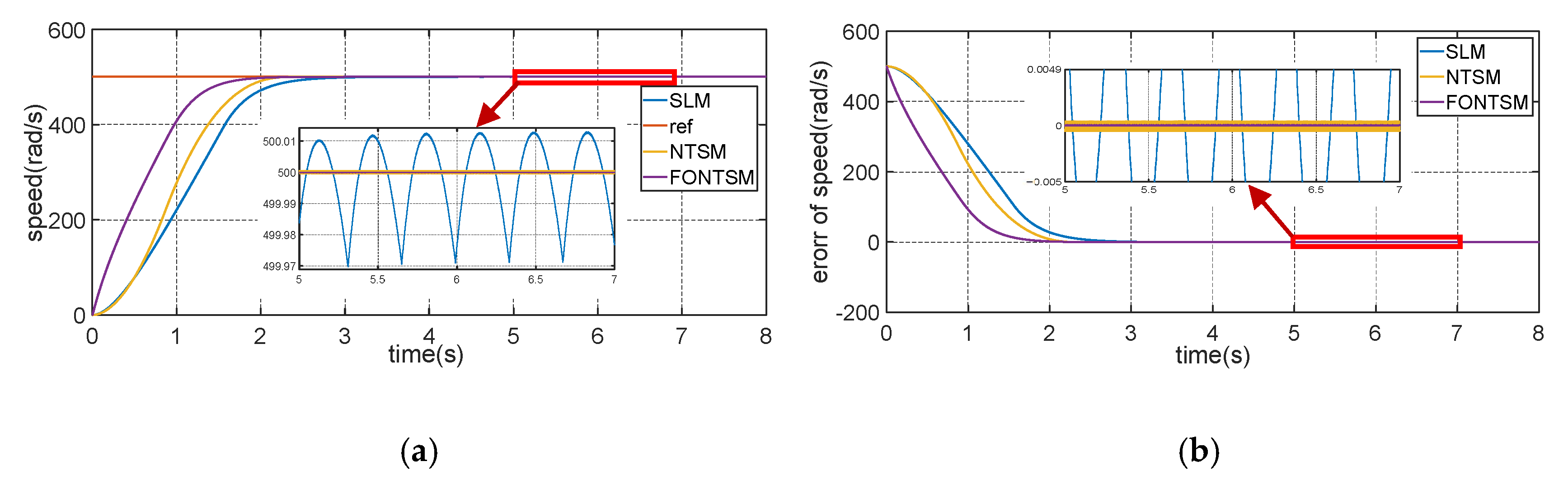
ωn = 500. The simulation results show that the response of the reference value was at 500 rad/s, as shown in the red line in
Figure 2. From the simulation results, the FONTSM controller achieved the highest efficiency with a convergence time of about 1.6 s, which is about 27.3% faster than the classic SLM controller of nearly 2.2 s and 15.8% faster than the improved NTSM controller of 1.9 s. The tracking error of the system was also much improved compared to the two classic controllers used in comparison with the proposed controller, specifically the tracking error of PID-nested NTSM, which is only about one. In addition, chattering is also an important factor to be considered in sliding mode control styles, which is caused by the discreteness of the control laws. SLM has a chattering amplitude of about
rad/s, and NTSM reduces this amplitude to
rad/s. The FONTSM controller virtually eliminates chattering, which improves the controller’s performance.
Figure 3 shows the motor torque and the control signal u, which can be used to evaluate the performance of the proposed controller. The results show the system’s stability during operation and the degree of oscillation and response of each control method. The results demonstrate the effectiveness of the controller. The chattering-free PID-nested NTSM controller almost eliminated the chattering phenomenon with a faster convergence time than the other methods compared, and the integral square and integral absolute error are shown in
Table 2 with impressive results of the proposed controller.
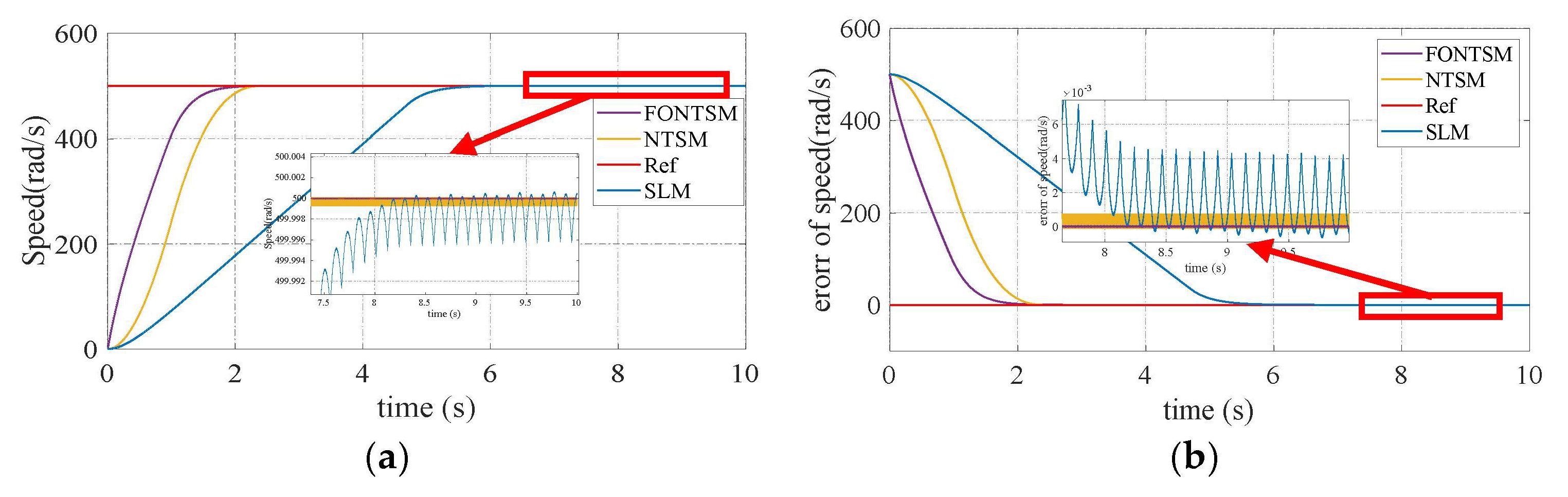
In special cases, the motor parameters are not specified exactly to check the response of the proposed controller. This also happens in cases where the motor parameters change during operation. Assuming that the motor parameters are increased three times compared to
Table 1, the response is depicted in
Figure 4. The results demonstrate that the controller response is faster with a faster convergence time, lower error, and reduced chattering, which is characteristic and the biggest drawback of sliding mode control.
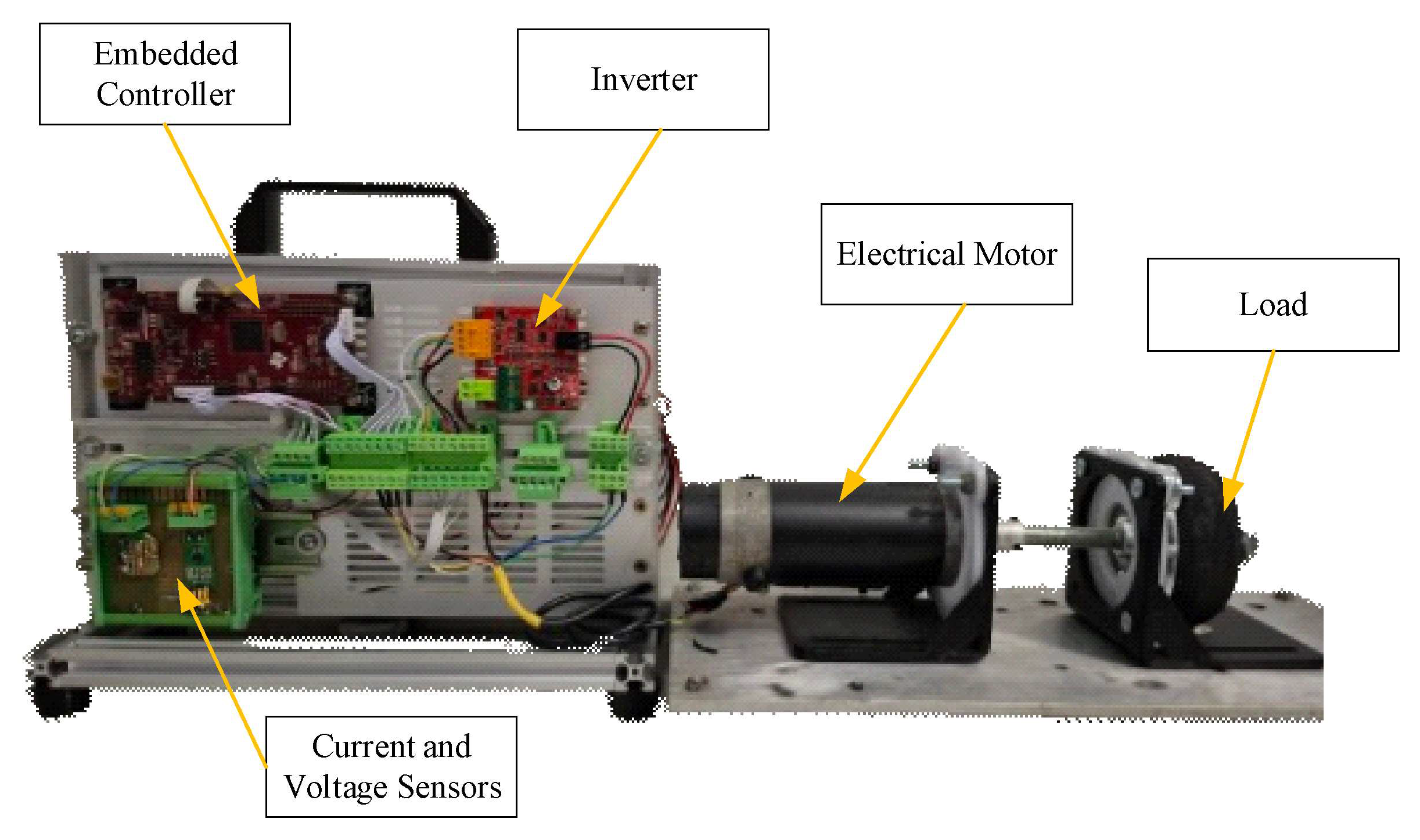
To evaluate the performance of the proposed controller, an experiment was set up, as shown in
Figure 5, which comprised key components such as an embedded controller, an inverter, an electric motor, and a load motor. A load motor was used to apply torque to the prime mover, simulating real-world load conditions. The load motor can act as a dynamometer, representing the loads applied to the prime mover under different load conditions and demonstrating the responsiveness of the proposed controller. The results were collected to evaluate the responsiveness of the proposed controller with sliding surfaces that are combinations of both integral and derivative errors of the states into nonsingular terminal sliding manifolds. The actual experiment results are shown as the response graph in
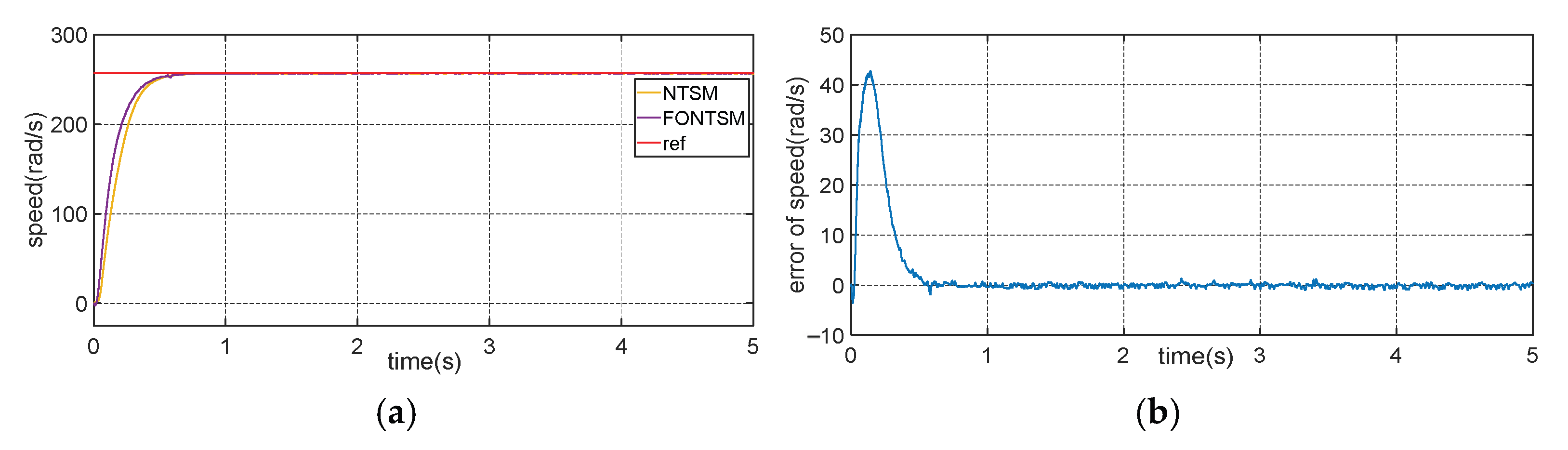
Figure 6. The proposed controller has a fast response and low error. The system converged chattering-free to zero, which proves the effectiveness of the controller, and the results are shown in the simulation results.
The results show that both controllers achieve a reference speed, but there are significant differences in convergence time and accuracy. The proposed controller (the blue line) achieved a steady state speed faster than the NTSM (the red line), with a convergence time of about 0.1 s, while the NTSM took longer to reach a steady state. This demonstrates that the PID-nested NTSM controller has a faster response, improving the convergence speed compared to the traditional NTSM method. In addition, both methods maintain speed without significant oscillation in the stable region, demonstrating high stability and accuracy. However, the proposed method shows a lower tracking error, confirming that this controller not only helps the system achieve the desired speed faster but also improves the control quality by minimizing the stability error. The system error decreases sharply and gradually approaches 0 rad/s after about 0.1 s, indicating that the system achieves rapid convergence with a very small tracking error in the steady state. From 0.1 s onwards, the error fluctuates slightly at around 0 rad/s, but the oscillation amplitude is small, indicating that the system maintains high accuracy without a large oscillation. This proves the effectiveness of the proposed controller. The simulation and experimental results demonstrate the controller’s performance with finite convergence time, robustness to uncertainty, disturbances, and a lack of chatter.


