Abstract
In this paper, various types of quantum circuits for DES components are proposed to analyze the trade-offs in quantum resources for both DES and TDES block ciphers. Specifically, multiple optimized structures within the DES framework are devised, and by integrating different elements from each type, 34 possible configurations for the DES block cipher are generated. The required quantum resources for these configurations are then estimated, identifying not only qubit-optimized and depth-optimized circuits but also those achieving a balanced trade-off between qubit and circuit depth. Building on these optimized DES designs, TDES circuits are constructed, and the corresponding cost of a Grover-based attack on the TDES is estimated.
MSC:
81P68
1. Introduction
In this era of rapidly advancing information technology, protecting digitally stored data is now essential. Currently, data are protected using symmetric-key encryption algorithms (e.g., AES and TDES) and public-key cryptography (e.g., RSA and ECC). However, the advent of quantum computers has raised concerns about the security of existing encryption methods. Grover’s Algorithm, proposed by Lov Grover in 1996 [1], is known to accelerate brute-force attacks on symmetric-key cryptography. Additionally, in 1994, Peter Shor [2] proposed an algorithm capable of efficiently solving the fundamental mathematical problems underlying existing public-key encryption systems, such as integer factorization and discrete logarithm problems, using quantum computers.
As quantum computers continue to advance, traditional cryptographic techniques face potential threats, prompting the transition to Post-Quantum Cryptography. However, this transition requires a significant amount of time, and classical cryptographic systems are still widely used. Therefore, while transitioning to quantum-resistant cryptography is essential, it is equally important to accurately assess how long the security of classical cryptographic algorithms will remain valid. For this reason, optimizing the quantum circuit implementation of classical cryptography allows for estimating the quantum resources required to execute Grover’s algorithm, thereby evaluating its level of quantum security. The optimization of quantum circuits primarily focuses on qubit count and circuit depth—where the number of qubits directly affects the operation of a quantum computer, and circuit depth significantly impacts error rates. Since it remains uncertain which aspect of quantum computing will achieve superior performance, research in both directions is essential. Due to this necessity, research on optimizing block ciphers into quantum circuits and estimating the corresponding quantum resources has been continually conducted over an extended period [3,4,5,6,7,8,9,10,11].
This paper presents a comprehensive analysis of quantum resources for the Data Encryption Standard (DES) and its security-enhanced version, Triple-DES (TDES). TDES was developed to address the vulnerabilities of DES, particularly its susceptibility to brute-force attacks due to its relatively short key size. Despite the compromised security of DES and recommendations to adopt AES as a more secure alternative, transitioning to AES poses practical challenges, such as device replacement and system updates. As a result, TDES remains in use due to these logistical difficulties. In this paper, we designed optimized quantum circuits for DES, as utilized in TDES, from two perspectives: qubit-optimization and depth-optimization. To achieve these, we constructed various optimized structures within DES components and explored a total of 34 possible circuit configurations by integrating elements from different optimization approaches. We implemented a quantum circuit and estimated the required resources using the quantum programming tool ProjectQ [12,13]. From the quantum resource estimation results, we identified both the qubit-optimized and depth-optimized DES quantum circuits and explored circuit configurations that achieve a balanced trade-off between qubit count and circuit depth. Based on these findings, we designed an optimized TDES and estimated the quantum resource cost for executing a Grover attack on TDES.
Contribution
- Optimized Quantum Circuit Components for DES and TDES: Our research proposes optimized quantum circuit designs for DES and TDES. We introduce two optimized designs for the expansion P-Box and four for the S-Box, incorporating both depth-optimized and qubit-optimized structures based on their characteristics.
- Quantum Resource Trade-off Analysis: We evaluated various TDES quantum circuits by analyzing different component combinations. Notably, optimizing individual components does not lead to linear improvements in overall circuit performance due to the complex interplay of parallel operations in quantum circuits.
- First Quantum Resource Evaluation of TDES in Grover’s Algorithm: This paper presents the most optimized TDES design, and we evaluated the quantum resources for Grover’s Algorithm.
2. Background
2.1. Data Encryption Standard (DES)
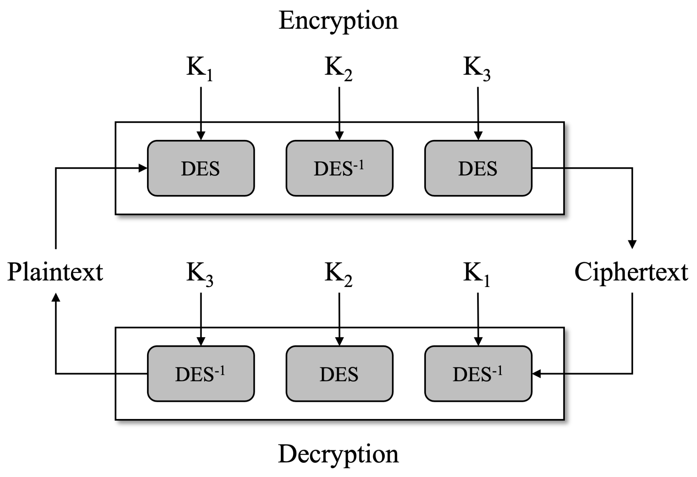
DES [14], developed in the 1970s, is a symmetric-key encryption algorithm that initially provided robust security but gradually revealed vulnerabilities over time. It uses a 56-bit key to encrypt 64-bit data blocks, employing 16 rounds of subkey generation and permutation–substitution processes for encryption. However, with the rapid advancement of computing technology, DES has become increasingly susceptible to attacks, weakening its security. This led to the need for stronger encryption alternatives in the 1990s. As a response to DES’s security vulnerabilities, Triple-DES (TDES) was developed to enhance security by applying DES encryption three times in succession. It uses a 168-bit key (56 × 3) for encryption and decryption, though its actual security strength is evaluated to be 112 bits. As a result, TDES offers significantly enhanced security compared to DES. However, the increased computational complexity of the algorithm introduces performance degradation concerns. Due to these limitations, AES is the recommended encryption standard. Nevertheless, some systems that have not yet transitioned continue to use TDES. Figure 1 illustrates the operation of TDES, which consists of three DES encryption modules.
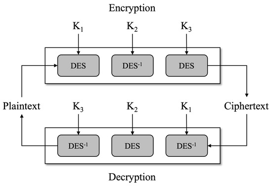
Figure 1.
TDES algorithm with three DESs.
2.2. Grover Algorithm
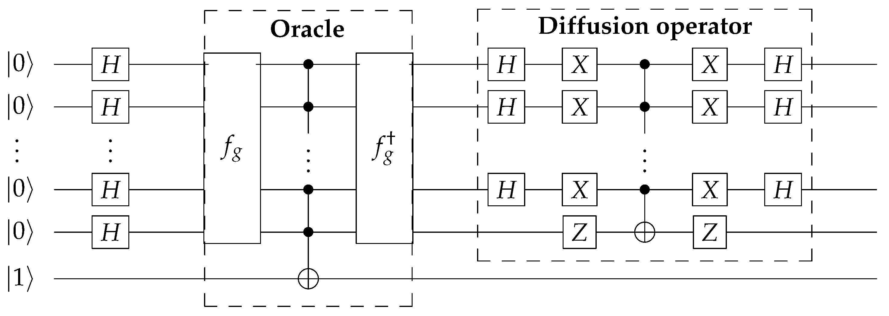
Quantum computers have the potential to significantly improve the efficiency of certain computational tasks compared to classical computers. One such task is searching for specific n-bit data in an unsorted list, where classical algorithms typically require operations. However, by employing the Grover algorithm on a quantum computer, the search complexity can be reduced to . The Grover algorithm for pre-image attacks consists of two main components: an Oracle and a Diffusion operator, as shown in Figure 2. This is designed for known-plaintext attacks (KPAs) in block ciphers (hash functions), where both the plaintext–ciphertext pairs are known. The Oracle function includes both the hash function and its inverse operation . When the result of matches the target hash value y, the Oracle sets . The Diffusion operator is then applied to enhance the probability of observing this state. Through approximately iterations of the Grover algorithm, the probability of measuring the correct solution qubit can be significantly increased.

Figure 2.
Grover algorithm with , adapted from Figure 2 in [15].
3. Flow of Quantum Circuit for DES and TDES
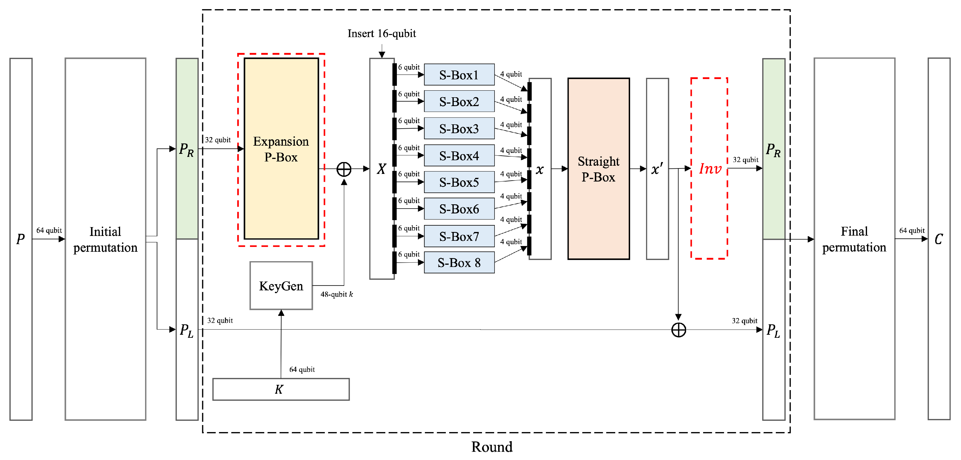
In this section, we present the quantum circuit flow for DES, which serves as a fundamental component in the operation of Triple-DES (TDES). The proposed DES quantum circuits are combined to construct TDES. Figure 3 illustrates the overall structure of a basic DES quantum circuit. The basic DES quantum circuit structure was implemented by following the operation method and sequence of the original DES. Based on this structure, we performed optimizations both structurally and at the component level.
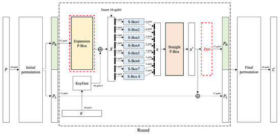
Figure 3.
The overall flow of a basic DES quantum circuit: The 64-bit input of DES is rearranged in the initial permutation using SWAP gates. The rearranged 64-bit data are then split into two 32-bit blocks: (right) and (left). In the final step of the round function, is XORed with . undergoes the expansion P-box operation and is then XORed with the key. The 32-bit is expanded to 48 bits using 16 additional qubits, and the expanded qubits are divided into eight 6-bit blocks, which serve as inputs to the S-Boxes. Each S-Box processes its 6-bit input and outputs a 4-bit value, producing a total of 32 bits. These 32 bits are then rearranged in the Straight P-box using SWAP gates. The inverse operation (red box: ) restores the original by inverting the expansion P-Box. This process is repeated for rounds, and after the final round, the Final Permutation is applied to produce the final ciphertext.
First, a 64-qubit plaintext is processed through initial permutation, resulting in two 32-qubit blocks, denoted as and . In DES, is expanded to a 48-qubit block using the expansion P-Box (EPB). Then, the expanded is XORed with a 48-bit key k: EPB . Expanding 32 bits to 48 bits requires 16 ancillary qubits in the expansion P-Box (basic case). After XORing with the key, the 48-qubit X is divided into eight 6-qubit groups. Each group is input into the S-Box1 to 8, producing a four-qubit output. The eight groups of 6-bit inputs into the S-Boxes output eight groups of 4 qubits, composing a 32-bit block denoted x. x is rearranged using the straight P-Box: SPB(x) , then performs a CNOT gate operation on . The is inverted to its initial state by applying the inverse operations of EPB and CNOT(). This ensures its proper use in the next round. After repeating these processes for a number of rounds, it is rearranged through Final Permutation to output 64-qubit cipher text.
We modified the flow of the basic DES quantum circuit to construct both a qubit-optimized quantum circuit and a depth-optimized quantum circuit. In quantum circuits, it is not possible to reset the state of the qubits that have been used. Therefore, to store the result of a function while maintaining the input x, one approach is to store it in an ancilla qubit t: . Another approach is to retrieve the original x through an inverse operation after using , expressed as . Indeed, storing the result in an ancillary qubit (t) is considered a depth optimization technique in quantum circuits. Storing the result in an ancillary qubit increases the number of qubits but minimizes the need for inverse operations, resulting in a low-depth quantum circuit. This trade-off can be advantageous in cases where minimizing circuit depth is a priority. Conversely, using inverse operations to recover the original input allows qubit reuse, reducing the overall qubit count but increasing circuit depth. This perspective is known as qubit optimization in quantum circuits. This trade-off can be beneficial in scenarios where minimizing qubit usage is a priority. To analyze the trade-offs in quantum resources, we examine the effects of applying the previously mentioned optimization components to both qubit-optimized and depth-optimized quantum circuits. The proposed combinations of DES quantum circuits are shown in Table 1.

Table 1.
Combinations for the DES quantum circuit.
In qubit-optimized quantum circuits, ancillary qubits are reused by applying the inverse operation to reset them to their initial states after use, while in depth-optimized circuits, new ancillary qubits are allocated each time they are required. Consequently, qubit-optimized quantum circuits have greater depth due to the additional inverse operations required to reset and reuse ancillary qubits within the round function. On the other hand, depth-optimized quantum circuits allocate qubits for all operations requiring ancilla in the round function, increasing the total qubit usage, but not including additional depth from inverse operations needed for qubit reuse. For straight P-Box and permutation operations, ancillary qubits are not used, meaning they behave identically in both qubit-optimized and depth-optimized designs. The TDES operates by performing DES encryption three times. Consequently, we can combine the proposed DES circuits to design the TDES and estimate the required quantum resources. In Section 5, we analyze the most optimized quantum circuit for the DES, which serves as the basis for designing the TDES. the TDES is constructed based on the quantum circuit that is most optimized for DES.
4. Components of the Quantum Circuit for DES
4.1. Key Generator
The key generator within the quantum circuit modifies qubit indices according to the DES rules. From the initial 64-bit master key K, a 56-bit round key k is generated, from which 48 bits are used in the internal function of each round. The alignment of qubit indices is determined based on Round r and the Permuted Choice 1 (PC-1) table. The PC-1 table is defined as follows:
In the quantum circuit, qubit indices can be rearranged using SWAP gates. The gate exchanges the states of two qubits: . Since this gate only performs simple qubit reordering rather than arithmetic operations, it incurs no quantum cost. In the key generator, the arrangement of qubit indices is determined based on Round r and the PC-1 table, which is processed in three main stages. In this first step, we consider a special case where . Under this condition, the following procedure is followed: The 64-bit master key K is updated to a 56-bit key using SWAP gates, based on the specified mapping defined as Parity drop table for . After the first round , this process is omitted, and the procedure proceeds directly to the final step.
In Step 2, the updated 56-qubit key K from Step 1 is divided into two distinct 28-qubit groups based on the specified indices: . The two groups are then left-shifted according to predefined rules. In this paper, the function responsible for executing the left shift operation is referred to as . Each group ( and ) serves as input to , modifying their indices. The result of , which operates with two inputs G and r, yields 28-bit values and . These values are stored in G-qubits: . uses a SWAP gate to shift indices to the left. The shift size is determined by the value of r: If r is 1, 2, 9, or 16, the shift size is 1; for all other values of r, the shift size is 2.
In the final step, only the indexes from 0 to 47 (a total of 48 qubits) of the rearranged 56-qubit , obtained from the second step, are selected. These 48 qubits then constitute the round key k. k is arranged as according to the indexes defined in the Permuted Choice 1 (PC-1) table. The three steps in the key generator use only SWAP gates, which do not impact the quantum cost of the quantum circuit. As a result, the key generator does not contribute to the final quantum resource calculations.
4.2. Initial Permutation
In the initial permutation, the 64-qubit x is rearranged into an array and then divided into two data blocks, L and R. In this paper, the initial permutation function is denoted as . The two blocks obtained through the initial permutation each consist of 32 qubits. The permutation follows the Initial Permutation Table (IPT) used in DES. The permutation follows the Initial Permutation Table (IPT) used in DES. The initial permutation can be implemented using SWAP gates, and the output is given by IPIPT, .
The output of the initial permutation, IP, is divided into two 32-qubit blocks: and , which are used in the next computation. The initial permutation is implemented using SWAP gates to rearrange the qubits according to the Initial Permutation Table (IPT). Since only SWAP gates are used, the initial permutation is not included in the quantum resources estimation. This means that the initial mutation does not contribute to estimating the resources required for the quantum circuit.
4.3. Expansion P-Box
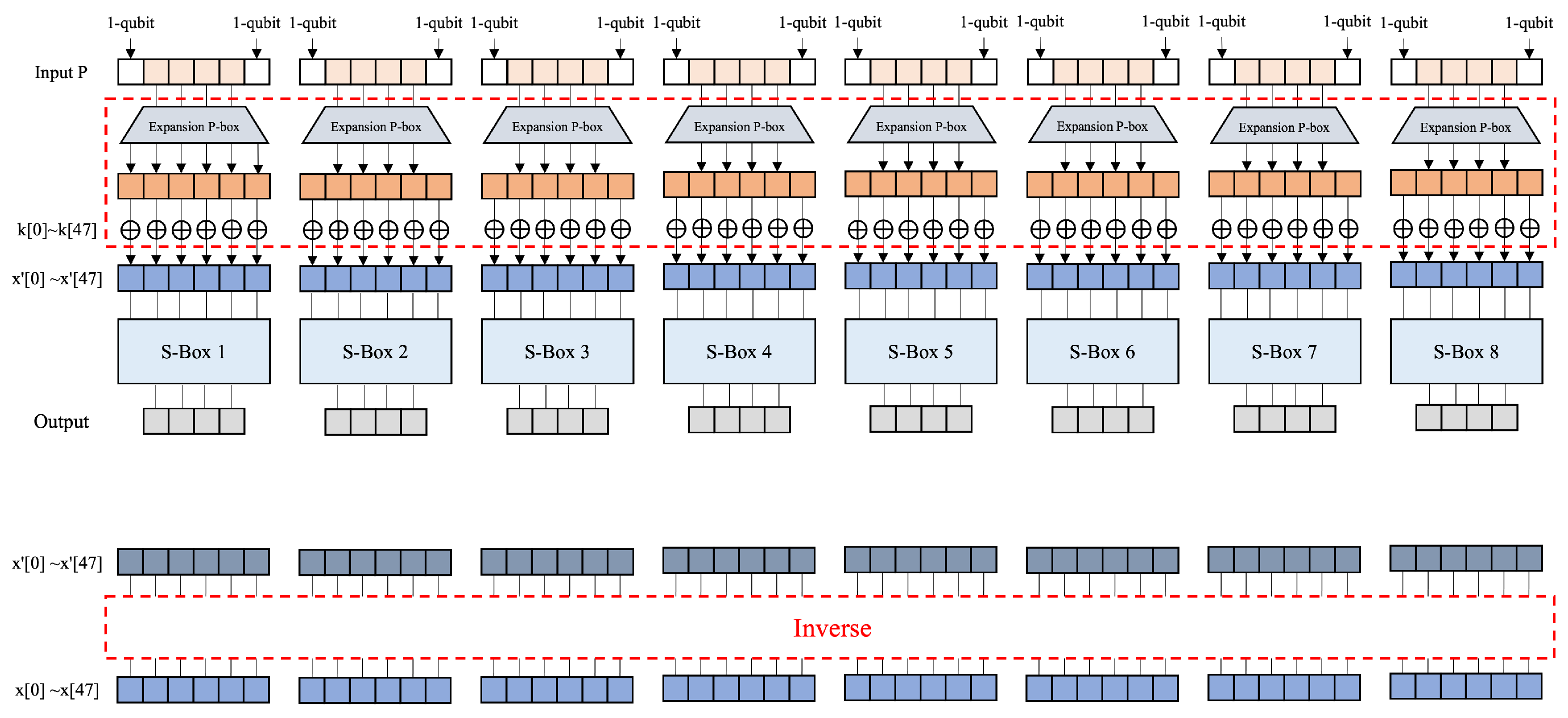
The expansion P-Box generates a 48-qubit output from a 32-qubit input, meaning it cannot store all 48 bits within the original 32-qubit input. Therefore, to accommodate all 48 bits, an additional qubits must be allocated. In the DES algorithm, the expansion P-box operates once per round, requiring qubits. In TDES, the expansion P-box is utilized times due to the three DES stages involved in the TDES process. The expansion P-Box in DES takes a 32-qubit input P and divides it into eight groups of 4 qubits. Each of these groups is then expanded into 6 qubits, resulting in a 48-qubit output: , , , , , , , → expansion P-Box . Redundantly used indexes are stored in 16 qubits through the CNOT gate, and the indexes are rearranged using SWAP gates. Eight groups extended to a length of six: , , , , , , , , are operated with a 48-qubit round key and CNOT gates, and each input to eight S-Boxes. Figure 4 illustrates the process of the basic quantum circuit of the expansion P-Box.
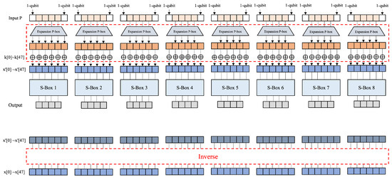
Figure 4.
The basic expansion P-Box: The 4-bit input is padded with clean ancilla qubits on both sides, expanding it to a 6-bit value x. This expanded value serves as the input to the Expansion P-box. The output from the Expansion P-box is then XORed with the key k ( CNOT). Each S-Box processes the 6-bit input and produces a 4-bit output. The changed is then processed by inverting the operations in the red-dotted section to restore the original x.
Optimized Expansion P-Box
We propose two optimized types of expansion P-Box. Unlike the Basic expansion P-Box (Figure 4), these methods do not require additional qubits or quantum gates. Instead, they modify the S-Box structure to bypass the expansion P-box, indirectly optimizing it rather than modifying it directly. Since the primary goal is to reduce quantum resources in the expansion P-Box, this approach is classified as an optimized expansion P-Box. Figure 5 and Figure 6 illustrate two types of optimized expansion P-Box: Type A and Type B, with further details provided in the following sections. There are two types of optimized expansion P-Boxes, Type A and Type B, which are as follows.
- : The message expansion process is skipped. An XOR operation is performed on the message P and key k at the expansion location: k ← CNOT; (e.g., ← CNOT). The k is used as input to the S-Box. Once it is used in the S-Box, the k is inverted back to its original value. This method requires an operation to invert k, and the S-Boxes operate in parallel.
- : The message expansion process is skipped. An XOR operation is performed on P and k at the expansion location: P ← CNOT; (e.g., ← CNOT). In this method, the eight S-Boxes cannot operate in parallel because the expanded indices overlap. To address this limitation, only S-Boxes with non-overlapping indices operate in parallel: Parallel 1 includes S-Boxes 1, 3, 5, and 7; Parallel 2 includes S-Boxes 2, 4, 6, and 8. This approach enables efficient parallel processing without any index conflicts. First, after completing the first parallel S-Box operation, the P is restored through an inverse function. The returned P is XORed with the appropriate k and used as the input for the second parallel operation. After completing the operations of the second parallel set of S-Boxes, the inverse function is applied to invert the value of P to its original state.
| S-Box1: P[31], P[0], P[1], P[2], P[3], P[4] | S-Box2: P[3], P[4], P[5], P[6], P[7], P[8] |
| S-Box3: P[7], P[8], P[9], P[10], P[11], P[12] | S-Box4: P[11], P[12], P[13], P[14], P[15], P[16] |
| S-Box5: P[15], P[16], P[17], P[18], P[19], P[20] | S-Box6: P[19], P[20], P[21], P[22], P[23], P[24] |
| S-Box7: P[23], P[24], P[25], P[26], P[27], P[28] | S-Box8: P[27], P[28], P[29], P[30], P[31], P[0] |
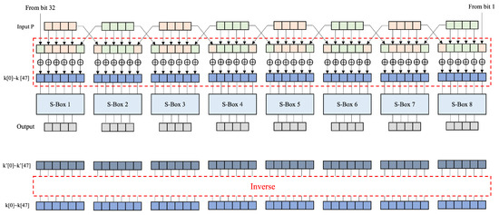
Figure 5.
The Type A expansion P-Box: Each 32-bit input P is divided into eight 4-bit blocks. The blocks at both ends are used to XOR with the key k from both sides . Since the XOR result is stored in the key k, P remains unaffected and can be reused. The modified key is then used in the S-Box to obtain the output. Finally, is processed by inverting the operations in the red-dotted box to restore the original key k.
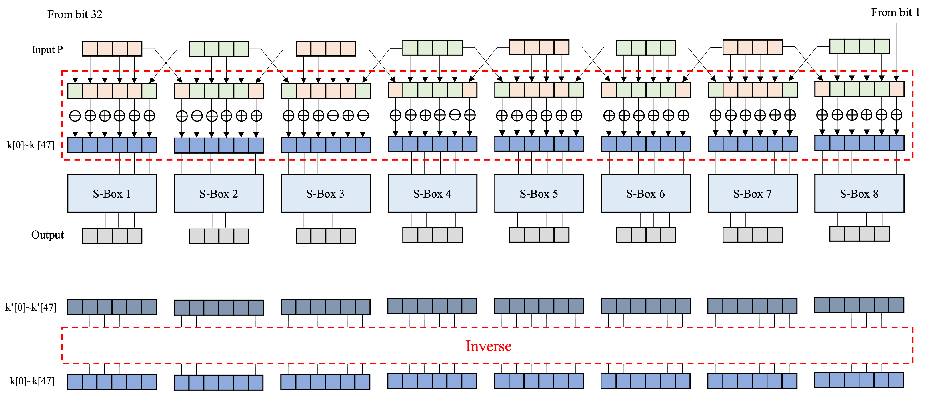
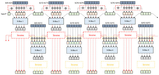
Figure 6.
The Type B expansion P-Box: For each input, the key k is XORed to P, and the XORed value serves as the input to the S-Box. The odd and even S-Boxes operate sequentially rather than simultaneously. This is because the P at both ends are required, preventing adjacent input blocks from being used simultaneously. First, the even S-Boxes generate their outputs. Then, the XORed are inverted (red-dotted box) to restore the original P. After this restoration, the odd S-Boxes operate in parallel. Finally, their outputs are inverted (yellow-dotted box) to return the original P.
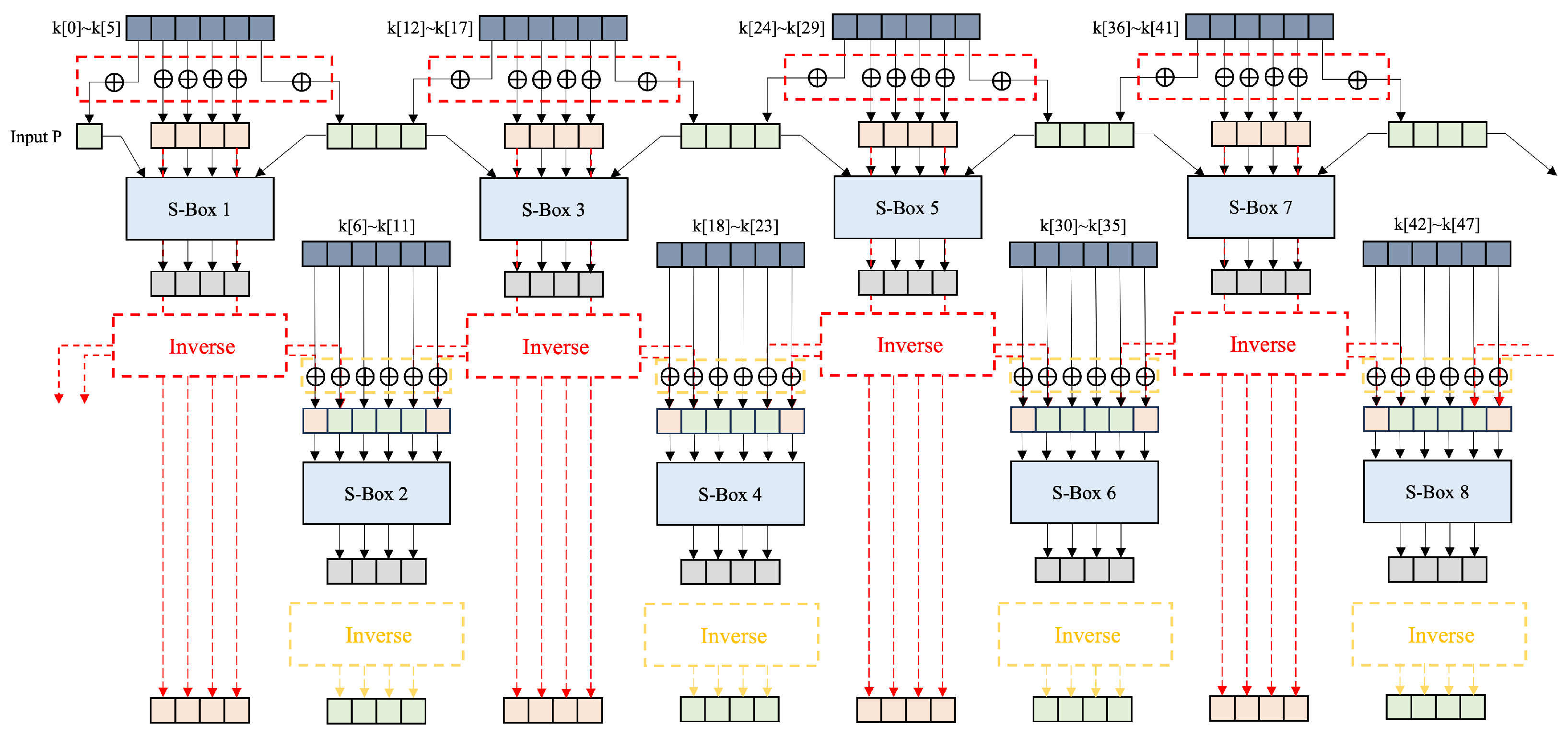
The two types of expansion P-Boxes can reduce 16(ancilla) × 16(r) = 256 qubit in a single DES operation (DES: 256 qubit, TDES: 768 qubit). One of the differences between the two types is the storage location of the key XOR result between k and P. (Type A: k, Type B: P): Algorithms 1 and 2 show the key XOR required for the optimized expansion P-Box for the two types. Another difference lies in the parallelizability of the S-Box. Type A allows for the parallel processing of eight S-Boxes, whereas Type B allows for the parallel processing of only four S-Boxes at once.
| Algorithm 1 Key XOR in expansion P-Box Type A |
| Input: 1: ← 2: ← 3: ← 4: ← 5: ← 6: ← return: |
| Algorithm 2 Key XOR in expansion P-Box Type B |
| Input: 1: ← 2: ← 3: ← 4: ← 5: ← 6: ← return: |
Table 2 and Table 3 show the estimation results of quantum resources by applying expansion P-Box Types A and B to the quantum circuit. The qubit-optimized quantum circuit is difficult to work with expansion Type B, so we exclude that combination. In comparison to the basic implementation, Type A has reduced the number of qubits by 256 in both quantum circuits, while Type B has decreased the number of qubits but has increased the depth. In the depth-optimized quantum circuit, both Type A and B utilize the same number of qubits and quantum gates, but significant reductions in depth have been achieved in Type A. Indeed, even when employing the same quantum gates, it is possible to reduce the depth through structural design.
Table 2.
The estimation results of quantum resources by applying expansion P-Box Types A and B to the depth-optimized quantum circuit.
Table 3.
The estimation results of quantum resources by applying expansion P-Box Types A and B to the qubit-optimized quantum circuit.
4.4. S-Box
DES uses eight S-Boxes, each S-Box takes a six-bit input and produces a four-bit output. In quantum circuits of the S-Box, using a Lookup Table (LUT) for array indexing is inefficient. Therefore, we referred to the Algebraic Normal Form (ANF) implementation [16]. As proposed in [16], there are two approaches to bitslice implementation: one composed of standard gates and the other composed of non-standard gates. This paper presents quantum circuit implementations for both methods. Table 4 and Table 5 present an estimation of quantum resources for the standard gates S-Box and non-standard gates S-Box, respectively. The two bitslice S-Boxes show a difference of 40 qubits and a depth of 7 through a slight trade-off for quantum gates. We compare the trade-off for quantum resources using both S-Box versions for the proposed TDES. In this paper, the S-Box composed of standard gates is written as S-Box Version 1, and the S-Box composed of non-standard gates is written as S-Box Version 2.
Table 4.
Estimation of quantum resources for S-Box quantum circuits composed of standard gates.
Table 5.
Estimation of quantum resources for S-Box quantum circuits composed of non-standard gates.
Optimized S-Box for DES
The two proposed types of S-Box are as follows: These approaches allow for the more efficient utilization of quantum resources and optimization of the qubit count. Table 6 summarizes the S-Box types, and the details are written in the text.
- Type A S-Box: A single ancilla n-qubit is continuously reused across S-Box 1 to S-Box 8. The inverse point of the ancillary qubit remains the same throughout all S-Boxes. However, instead of storing results in ancillary qubits, four dedicated qubits are assigned for each S-Box to store the result. Therefore, a total of 512 qubits are additionally required, calculated as follows: S-Box count(8) × Result qubits per S-Box(4) × r(16). In this approach, after an ancilla qubit is used in an S-Box, all of them are reset using the inverse operation. As a result, the reset ancillary qubits become available for reuse in subsequent S-Box operations. By utilizing inverse operations, ancilla qubits can be reused, reducing the overall qubit count compared to the basic implementation. However, because each S-Box must be fully processed before moving to the next, parallel operation is impossible, leading to increased circuit depth. The ancilla qubit required for the next S-Box is maintained, and an inverse operation is added per S-Box for initialization. In the last round, the ancilla inverse operation is omitted.
- Type B S-Box: This approach assigns four qubits to store the results of each S-Box operation. Consequently, a total of 512 additional qubits are required, calculated as follows: S-Box count(8) × Result qubits per S-Box(4) × r(16). Ancilla arrays are allocated separately for each S-Box, enabling parallel operation. After completing their use in the S-Box, all ancilla qubit arrays are reset through inverse operations, making them available for reuse in the next round. This allows for efficient ancilla qubit recycling, potentially reducing the total number of qubits required for the implementation. All ancilla qubits used in previous rounds are preserved and can be reused in subsequent rounds. An inverse operation is added per round for ancilla qubit initialization, but in the last round, the inverse operation is omitted.
Table 6.
Characteristics of different types of S-Boxes.
4.5. Straight P-Box
The straight P-Box (SPB) rearranges the bits of a 32-bit qubit X based on the predefined Straight Permutation Table (SPT) as follows:
| X0 | X1 | X2 | X3 | X4 | X5 | X6 | X7 | → | X15 | X6 | X19 | X20 | X28 | X11 | X27 | X16 |
| X8 | X9 | X10 | X11 | X12 | X13 | X14 | X15 | X0 | X14 | X22 | X25 | X4 | X17 | X30 | X9 | |
| X16 | X17 | X18 | X19 | X20 | X21 | X22 | X23 | X1 | X7 | X23 | X13 | X31 | X26 | X2 | X8 | |
| X24 | X25 | X26 | X27 | X28 | X29 | X30 | X31 | X18 | X12 | X29 | X5 | X21 | X10 | X3 | X24 |
The described rearrangement of qubits uses only the SWAP gates. This module is not considered in the estimation of quantum resources as it does not utilize any quantum resources other than the SWAP gate.
4.6. Final Permutation
The Final Permutation (FP) operates on after completing all round functions. The final ciphertext is obtained by rearranging the 64-bit qubit C using the predetermined Final Permutation Table (FPT). The operation of the Final Permutation is as follows. As with the Straight P-Box, the rearrangement of the qubits in the Final Permutation is only performed via the SWAP gate and is therefore excluded from the quantum resource estimation.
| C0 | C1 | C2 | C3 | C4 | C5 | C6 | C7 | → | C39 | C7 | C47 | C15 | C55 | C23 | C63 | C31 |
| C8 | C9 | C10 | C11 | C12 | C13 | C14 | C15 | C38 | C6 | C46 | C14 | C54 | C22 | C62 | C30 | |
| C16 | C17 | C18 | C19 | C20 | C21 | C22 | C23 | C37 | C5 | C45 | C13 | C53 | C21 | C61 | C29 | |
| C24 | C25 | C26 | C27 | C28 | C29 | C30 | C31 | C36 | C4 | C44 | C12 | C52 | C20 | C60 | C28 | |
| C32 | C33 | C34 | C35 | C36 | C37 | C38 | C39 | C35 | C3 | C43 | C11 | C51 | C19 | C59 | C27 | |
| C40 | C41 | C42 | C43 | C44 | C45 | C46 | C47 | C34 | C2 | C42 | C10 | C50 | C18 | C58 | C26 | |
| C48 | C49 | C50 | C51 | C52 | C53 | C54 | C55 | C33 | C1 | C41 | C9 | C49 | C17 | C57 | C25 | |
| C56 | C57 | C58 | C59 | C60 | C61 | C62 | C63 | C32 | C0 | C40 | C8 | C48 | C16 | C56 | C24 |
5. Analysis of Quantum Resources
In this section, we identify a number of combinations of quantum circuits by integrating DES components (i.e., P-Box, S-Box). Based on these results, we analyze the trade-offs in quantum resources. We identify DES quantum circuits optimized for qubits and depth based on the analyzed results. We then combine these to estimate the quantum resources required for TDES in Grover’s Algorithm. Finally, we compare the Grover resources of AES-128/192/256 and TDES to assess their quantum security strength.
Table 7, Table 8, Table 9 and Table 10 present the results of applying our optimization components to the depth-optimized and qubit-optimized structures, respectively. The comparison results indicate that in the depth-optimized structure, the circuit depth generally decreased, whereas in the qubit-optimized structure, the number of qubits used tended to be reduced. These findings suggest that even when individual component optimizations are applied, the structural characteristics of the circuit influence the optimization direction. However, in certain cases (e.g., S-Box: B, P-Box: B), this trend did not hold. This implies that the combination of structural type and internal component optimization may yield optimal results in some cases but not in others.
Table 7.
Estimation of quantum resources for depth-optimized DES quantum circuits. (S-Box version 1: S-Box composed of standard gates in Table 4.)
Table 8.
Estimation of quantum resources for depth-optimized DES quantum circuits. (S-Box version 2: S-Box composed of non-standard gates in Table 5.)
Table 9.
Estimation of quantum resources for qubit-optimized DES quantum circuits. (S-Box version 1: S-Box composed of standard gates in Table 4.)
Table 10.
Estimation of quantum resources for qubit-optimized DES quantum circuits. (S-Box version 2: S-Box composed of non-standard gates in Table 5.)
Table 7 and Table 8 present the estimated quantum resource costs for depth-optimized DES quantum circuits. Among them, the DES quantum circuit with (S-Box: basic, P-Box: type A) is the most depth-optimized. Similarly, Table 9 and Table 10 show the resource estimates for qubit-optimized DES quantum circuits, with the DES quantum circuit (S-Box: basic, P-Box: type A) in these tables being the most qubit-efficient. The two optimized circuits differ by approximately 6120 to 6720 qubits and exhibit an 84% difference in circuit depth.
Table 11 compares our proposed DES quantum circuit with the results presented by Jang et al. [17]. Compared to their implementation, our depth-optimized circuit achieves a 68% reduction in circuit depth, while the qubit-optimized version reduces the qubit count by 6128. These results demonstrate that our proposed implementation outperforms previous work in terms of both qubit efficiency and circuit depth.
Table 11.
Estimation of quantum resources for the DES.
Furthermore, we estimated the cost of Grover’s Algorithm for TDES using our DES quantum circuit (Table 12) and compared it with AES (Table 13). TDES requires fewer qubits than AES for all key sizes, and it exhibits a smaller circuit depth than AES-192 and AES-256, potentially making it more vulnerable to Grover’s attack. However, compared to AES-128, TDES has lower qubit requirements but greater circuit depth, suggesting stronger quantum security in terms of depth. This finding underscores the need for the further assessment of quantum security as quantum computing technology advances, as a high level of classical security does not necessarily translate to high quantum security.
Table 12.
Quantum resources for the TDES in Grover’s algorithm.
Table 13.
Quantum resource comparison for Grover’s Algorithm of the TDES and AES.
6. Conclusions
In this paper, a number of quantum circuits for DES components were proposed to analyze the trade-off in quantum resources for DES and TDES circuits. By exploring different component types, multiple DES circuit configurations were designed and evaluated, identifying optimized quantum implementations in terms of qubit usage and circuit depth. Building on these optimized DES implementations, TDES quantum circuits were presented, and their resource efficiency was assessed. Optimal configurations that effectively minimize qubit count and circuit depth, specifically within TDES, were identified. This comprehensive analysis enabled the determination of the most resource-efficient quantum circuits for both DES and TDES, achieving an optimal balance between qubit usage and circuit depth. These findings demonstrate that quantum circuits can be designed with careful consideration of various factors, such as qubit count and circuit depth, allowing for flexible optimization based on different constraints. This implies that while it remains uncertain whether future large-scale quantum computers will achieve superior performance in terms of qubit count or error rates (depth), quantum circuits can be adapted accordingly to match their capabilities.
Author Contributions
Software, G.S.; Writing—original draft, G.S.; Writing—review & editing, S.Y. and H.S.; Supervision, H.S. All authors have read and agreed to the published version of the manuscript.
Funding
This research was financially supported by Hansung University.
Data Availability Statement
The data presented in this study are available on request from the corresponding author.
Conflicts of Interest
The authors declare no conflicts of interest.
References
- Grover, L.K. A fast quantum mechanical algorithm for database search. In Proceedings of the 28th Annual ACM Symposium on Theory of Computing, Philadelphia, PA, USA, 22–26 May 1996; pp. 212–219. [Google Scholar]
- Shor, P.W. Polynomial-time algorithms for prime factorization and discrete logarithms on a quantum computer. SIAM Rev. 1999, 41, 303–332. [Google Scholar] [CrossRef]
- Grassl, M.; Langenberg, B.; Roetteler, M.; Steinwandt, R. Applying Grover’s algorithm to AES: Quantum resource estimates. In Proceedings of the Post-Quantum Cryptography, Fukuoka, Japan, 24–26 February 2016; Springer: Cham, Switzerland, 2016; pp. 29–43. [Google Scholar]
- Anand, R.; Maitra, A.; Mukhopadhyay, S. Grover on SIMON. Quantum Inf. Process. 2020, 19, 340. [Google Scholar] [CrossRef]
- Chauhan, A.K.; Sanadhya, S.K. Quantum resource estimates of grover’s key search on ARIA. In Proceedings of the Security, Privacy, and Applied Cryptography Engineering: 10th International Conference, SPACE 2020, Kolkata, India, 17–21 December 2020; Proceedings 10. Springer: Cham, Switzerland, 2020; pp. 238–258. [Google Scholar]
- Das, P.; Biswas, S.; Kanoo, S. Quantum implementation of SHA1 and MD5 and comparison with classical algorithms. Quantum Inf. Process. 2024, 23, 176. [Google Scholar] [CrossRef]
- Rahman, M.; Paul, G. Grover on KATAN: Quantum resource estimation. IEEE Trans. Quantum Eng. 2022, 3, 1–9. [Google Scholar]
- Huang, Z.; Sun, S. Synthesizing quantum circuits of AES with lower t-depth and less qubits. In Proceedings of the International Conference on the Theory and Application of Cryptology and Information Security, Taipei, Taiwan, 5–9 December 2022; Springer: Cham, Switzerland, 2022; pp. 614–644. [Google Scholar]
- Jang, K.; Baksi, A.; Kim, H.; Song, G.; Seo, H.; Chattopadhyay, A. Quantum analysis of AES. Cryptol. Eprint Arch. 2022. Available online: https://eprint.iacr.org/2022/683 (accessed on 30 March 2025).
- Zou, J.; Li, L.; Wei, Z.; Luo, Y.; Liu, Q.; Wu, W. New quantum circuit implementations of SM4 and SM3. Quantum Inf. Process. 2022, 21, 181. [Google Scholar] [CrossRef]
- Song, G.; Jang, K.; Seo, H. Improved Low-Depth SHA3 Quantum Circuit for Fault-Tolerant Quantum Computers. Appl. Sci. 2023, 13, 3558. [Google Scholar] [CrossRef]
- ProjectQ Framework. ProjectQ: An Open Source Software Framework for Quantum Computing. Available online: https://projectq.ch/ (accessed on 25 March 2025).
- ProjectQ Framework. ProjectQ GitHub Repository. Available online: https://github.com/ProjectQ-Framework/ProjectQ (accessed on 25 March 2025).
- FIPS PUB 46; Federal Information Processing Standards Publication 46. National Bureau of Standards: Gaithersburg, MA, USA, 1977.
- Song, G.; Eum, S.; Kwon, H.; Sim, M.; Lee, M.; Seo, H. Optimized Quantum Circuit for Quantum Security Strength Analysis of Argon2. Electronics 2023, 12, 4485. [Google Scholar] [CrossRef]
- Kwan, M. Reducing the Gate Count of Bitslice DES. IACR Cryptol. ePrint Arch. 2000, 2000, 51. [Google Scholar]
- Jang, K.b.; Kim, H.J.; Song, G.J.; Sim, M.J.; Woo, E.S.; Seo, H.J. Quantum Cryptanalysis for DES Through Attack Cost Estimation of Grover’s Algorithm. J. Korea Inst. Inf. Secur. Cryptol. 2021, 31, 1149–1156. [Google Scholar]
Disclaimer/Publisher’s Note: The statements, opinions and data contained in all publications are solely those of the individual author(s) and contributor(s) and not of MDPI and/or the editor(s). MDPI and/or the editor(s) disclaim responsibility for any injury to people or property resulting from any ideas, methods, instructions or products referred to in the content. |
© 2025 by the authors. Licensee MDPI, Basel, Switzerland. This article is an open access article distributed under the terms and conditions of the Creative Commons Attribution (CC BY) license (https://creativecommons.org/licenses/by/4.0/).