1. Introduction
Research on stability is essential across various disciplines [
1,
2,
3]. In mechanical studies, the operation of centrifugal compressors also encounters stability challenges. In industrial settings, the inlet and outlet of the centrifugal compressor connect the pipeline system. The centrifugal compressor and the pipeline system operate together and affect each other. When the resistance of the pipeline system increases, the flow rate of the centrifugal compressor decreases. The compressor will experience rotating stall and surge instabilities, which limit its stable operating range. Accurately measuring and capturing the characteristic signals of rotating stall and surge is crucial for ensuring the safe and stable operation of centrifugal compressors. The characteristics of rotating stall and surge and their instability mechanisms remain challenging in centrifugal compressor research [
4].
Rotating stall occurs due to flow separation within the internal flow passages of the centrifugal compressor. Emmons [
5] proposed the circumferential propagation of stall cells, elucidating the instability mechanism of rotating stall. Circumferential pressure disturbance signals have since been used as an effective method for detecting rotating stall. Researchers have experimentally measured these disturbance signals by installing dynamic pressure sensors circumferentially along the compressor shroud [
6,
7,
8,
9]. The propagation speed of stall cells is considered the characteristic frequency of rotating stall, although this frequency varies across different centrifugal compressors. Pullan et al. [
10] measured a rotating stall characteristic frequency at 76% of the rotor speed, while Lou et al. [
11] observed a characteristic frequency corresponding to one-third of the impeller rotation frequency. Some studies have reported even lower characteristic frequencies, ranging from 20% to 30% of the impeller rotation frequency [
12,
13]. Additionally, the location where stall cells originate varies with the compressor design [
14,
15], complicating the measurement of the rotating stall characteristics signal.
As the flow rate decreases further, rotating stall can induce low-frequency gas oscillations within the centrifugal compressor and the pipeline system, leading to surge [
16,
17]. Accurate surge measurement is critical for defining the compressor’s safe operating range. The characteristic frequency of the surge is notably lower than that of rotating stall, enabling differentiation between the two instability phenomena based on the frequency. However, the surge frequency is also influenced by the pipeline system [
18,
19,
20]. Some researchers have linked surge occurrence to system resonance by comparing experimentally measured surge frequencies with calculated Helmholtz resonance frequencies [
21,
22]. Given the complex interactions between the centrifugal compressor and the pipeline system, further investigation from a flow perspective is necessary to clarify the relationship between the surge and system resonance, providing insights into the instability mechanisms of centrifugal compressor surge.
When the centrifugal compressor is operating, a mutual influence exists between the centrifugal compressor and the pipeline system [
23]. Researchers have applied pressure disturbances at the compressor outlet to investigate the impact of pressure disturbances in the pipeline system on the compressor’s operation [
24,
25]. However, the influence of the pressure disturbance generated by the centrifugal compressor on the pipeline system under unstable conditions requires further investigation. The software ANSYS CFX 19.2, which utilizes the element-based finite volume method, integrates the accuracy advantages of the finite element method with the conservation properties of the finite volume method, offering both flexibility and high-resolution flux computation. This makes it a powerful and effective tool for analyzing the response of pipeline systems.
In this study, the flow responses in the pipeline system under a pressure disturbance related to rotating stall and surge are solved by numerical simulation. The mechanisms behind the distinct propagation behaviors of the two instability pressure disturbances are analyzed based on the flow results. Therefore, the instability of the two types of centrifugal compressors is identified by the response of the pipe flow. The investigations in this study provide a new measurement method for detecting the instability of centrifugal compressors, which is crucial for ensuring their safe and stable operation in industrial applications.
This study investigates the flow behavior of the pipeline system under unstable pressure disturbances from the centrifugal compressor using numerical simulation, exploring both instability phenomena of centrifugal compressors from the perspective of the pipeline system.
Section 2 presents the measurement results of the pipeline system during rotating stall and surge.
Section 3 outlines the numerical simulation model of the pipeline system.
Section 4 introduces the numerical simulation results under different characteristic frequency pressure disturbances.
Section 5 discusses the disturbance propagation mechanisms of the pipeline system under rotating stall and surge conditions.
Section 6 summarizes the study’s findings.
2. Experimental Results
In this study, instability experiments were conducted on a centrifugal compressor and pipeline system test rig at Xi’an Jiaotong University, as shown in
Figure 1. The test rig included a 75 kW centrifugal compressor, inlet pipe, outlet pipe, plenum, and valve. Detailed descriptions of the centrifugal compressor and sensors of the test rig are provided in the reference [
26].
To investigate the impact of centrifugal compressors on the outlet pipeline system, six dynamic pressure sensors (P5 to P10) were installed in the test rig’s pipeline system to measure the low-frequency pressure signals associated with compressor instability. The sensor installation positions are shown in
Figure 2. Compressor outlet sensors P5 to P8 were placed 0.1 m downstream of the centrifugal compressor volute outlet on the outlet pipe, spaced circumferentially at 90° intervals on the same cross section of the pipeline. Outlet pipe sensor P9 was positioned 1.9 m downstream of P5. The last sensor, P10, was located in the plenum. During the experiments, dynamic pressure signals were acquired using the NI-9220 and cDAQ-9189 data acquisition systems, with a sampling frequency of 1000 Hz.
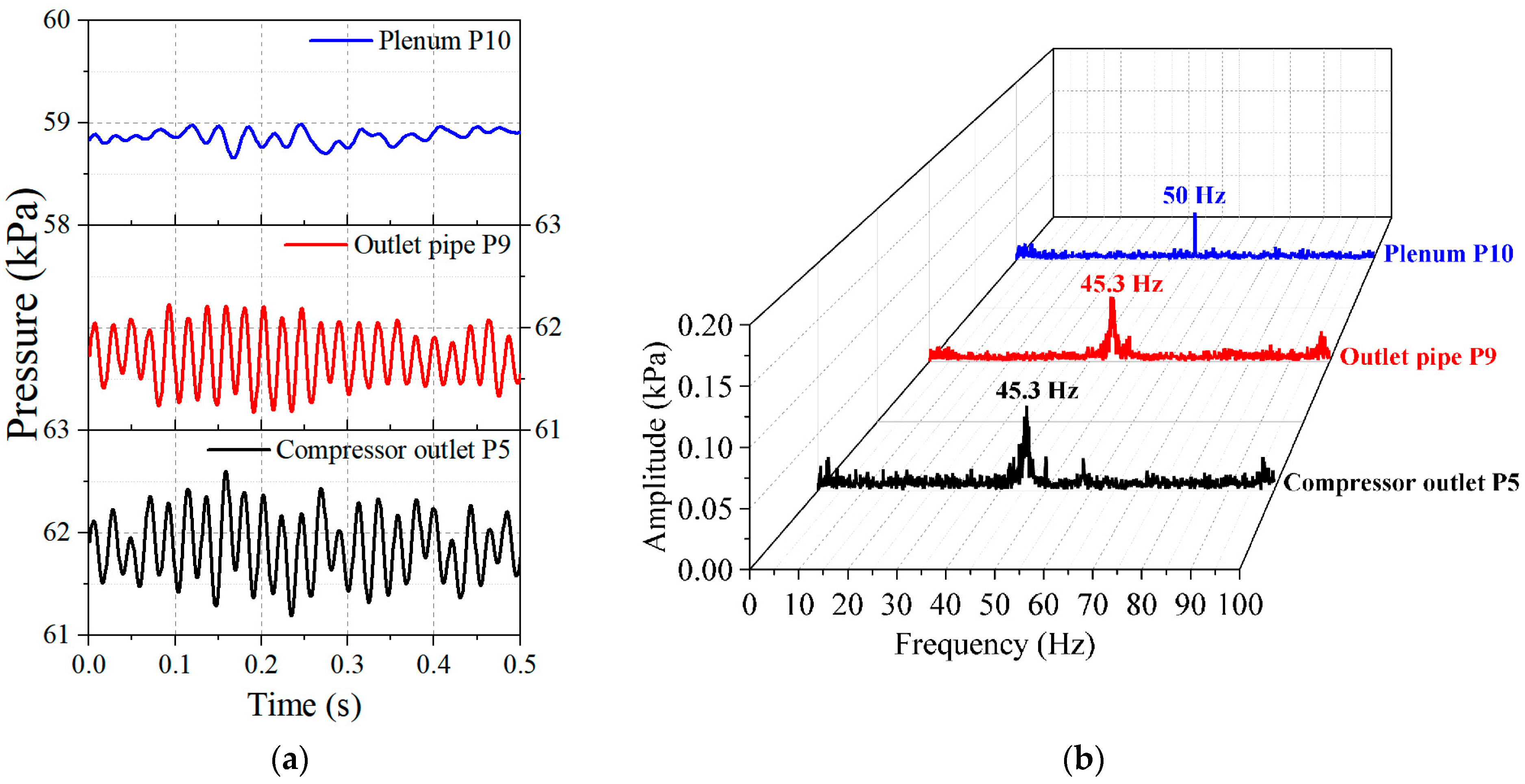
As the flow rate decreased to 27.97 m
3/min, abnormal pressure fluctuations appeared in the pipeline system. The test rig centrifugal compressor’s operation became unstable due to rotating stall. The dynamic pressure measurements at this flow rate, which were processed by a 50 Hz low-pass filter, are shown in
Figure 3. As shown in the figure, both the compressor outlet sensor P5 and the outlet pipe sensor P9 recorded sinusoidal pressure fluctuations at a frequency of 45.3 Hz. The characteristic frequency of the rotating stall was 45.3 Hz. This indicated that the instability of the centrifugal compressor led to pressure fluctuations in the pipeline system’s flow. The pressure disturbance from the compressor stall propagated from the P5 position to the P9 position in the flow direction.
However, the spectrum result of the pressure measurement result of P10 (
Figure 3b) showed that the peak frequency of the pressure fluctuation in the plenum was 50 Hz instead of 45.3 Hz. Since the alternating current frequency of the laboratory circuit was 50 Hz, the small amplitude fluctuations in the plenum were caused by interference from the current signal. The pressure fluctuation characteristics in the plenum were different from those in the outlet pipe. The 45.3 Hz pressure fluctuation propagating along the outlet pipe in the flow direction could not reach the downstream plenum. The unstable pressure disturbances in the centrifugal compressor, induced by rotating stall, caused varying responses at different locations within the outlet pipeline system of the test rig.
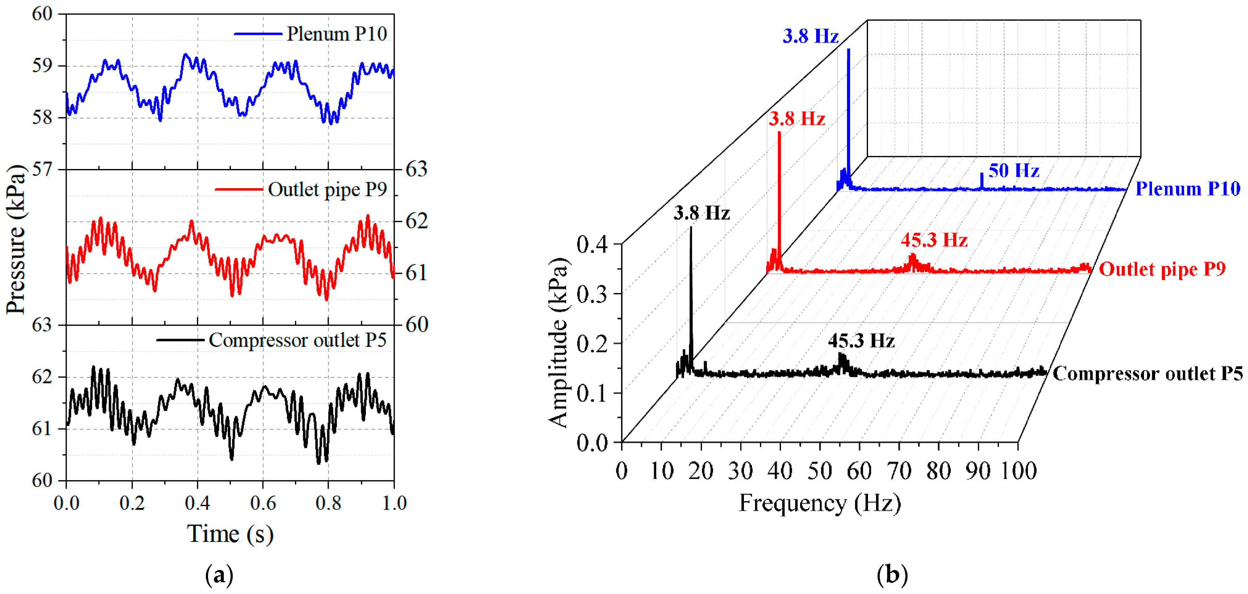
As the flow rate further decreased to 26.56 m
3/min, the pressure fluctuation curve changed significantly, as shown in
Figure 4. The pressure fluctuation frequency in the pipeline system was reduced from 45.3 Hz to 3.8 Hz. The type of instability in the test rig centrifugal compressor changed, indicating the onset of surge. Comparing
Figure 3b with
Figure 4b, the plenum’s 3.8 Hz pressure fluctuation was also measured when the surge occurred, which was different from the measurement results during the rotating stall. The entire outlet pipeline system became unstable under surge conditions, and the response of the pipeline system changed. Surge is an instability phenomenon in the whole system. For the test rig system used in this study, the characteristic surge frequency was 3.8 Hz.
In addition to the dominant 3.8 Hz peak frequency, a smaller peak at 45.3 Hz, corresponding to the rotating stall characteristic frequency, was also observed in the frequency spectra results of sensors P5 and P9. This indicates that rotating stall and surge can coexist during compressor instability. Similar to the measurement results of the rotating stall, the 45.3 Hz pressure fluctuation was not captured by sensor P10 in the plenum. When surge occurred in the test rig centrifugal compressor, it was accompanied by the rotating stall phenomenon. The pressure disturbances of two different frequencies caused two distinct response behaviors in the pipeline system, and these responses did not interfere with each other.
The experimental results on the centrifugal compressor instability demonstrate that rotating stall and surge generate pressure disturbances with distinct characteristic frequencies in the pipeline system, providing a novel approach for identifying the instability of centrifugal compressors. The rotating stall 45.3 Hz pressure disturbance propagates along the flow direction in the outlet pipe but does not reach the downstream plenum. Since pressure measurements cannot fully explain the absence of the rotating stall pressure fluctuation signals, numerical simulations are needed further to analyze the propagation characteristics of rotating stall pressure fluctuations. Moreover, the surge of the centrifugal compressor causes a 3.8 Hz pressure fluctuation in the entire pipeline system. When the frequency of pressure disturbance changes, the response of the pipeline system changes accordingly. This also requires an urgent study of the reasons for changes in the pipeline system’s response from a flow perspective, which will be beneficial for research on the centrifugal compressor instability mechanism.
3. Numerical Simulation Model of the Pipeline System
3.1. Computational Domain
The three-dimensional numerical simulation model of the test rig’s outlet pipeline system is shown in
Figure 5. The inlet of the computational domain was located at the centrifugal compressor outlet, while the outlet was positioned at the valve. The computational domain included four different parts: the outlet pipe, the plenum inlet pipe, the plenum itself, and the plenum outlet pipe. The outlet pipe had a diameter of 300 mm and a length of 2700 mm. The plenum inlet pipe had a diameter of 300 mm and a length of 925 mm. The plenum was manufactured by a 600 mm diameter and 2100 mm length pipe. The plenum outlet pipe had a diameter of 350 mm and a length of 1800 mm. These pipes were all sized to match the test rig’s actual pipeline system.
Numerical pressure probes were incorporated into the simulation to monitor the pressure at specific points and investigate the pressure disturbances at different locations in the pipeline system. The purple markers in
Figure 5 represent the positions of these probes. Probes M1 and M2 in the outlet pipe corresponded to the locations of dynamic pressure sensors P5 and P9 on the test rig. Probes M3 to M5 were positioned in the plenum inlet pipe. Four probes, M6 to M9, were placed within the plenum, with M6 aligning with the installation position of dynamic pressure sensor P10. The final probe, M10, was located in the plenum outlet pipe.
3.2. Governing Equations
To explore the pressure disturbance propagation behavior in the pipeline system, transient numerical simulations were conducted in the ANSYS CFX software. The three-dimensional unsteady Reynolds averaged Navier–Stokes (URANS) equations in ANSYS CFX, using the element-based finite volume method, obtained the flow field results of the pipeline system. The URANS governing equations are as follows:
where
is the density,
is the velocity vector,
is the static pressure,
is the temperature,
is the internal energy, and
is the thermal conductivity. The viscous stress tensor
is defined as follows:
where
is the dynamic viscosity,
is the strain rate tensor, and
is the unit tensor. To make the equations enclosed, the following equations should be added:
where
is the gas constant, and
is the specific heat at constant volume.
In this study, ideal air was chosen as the fluid in the simulation. The k-ε turbulence model was employed to achieve high accuracy in solving the pipe flow without a strong adverse pressure gradient. The second-order Euler backward scheme was employed for temporal discretization, which is a second-order implicit scheme. As for the spatial discretization of convective terms, this study used the high-resolution scheme with second-order accuracy. The numerical scheme combines the advantages of the upwind scheme and the central differencing scheme, taking into account both convergence and accuracy.
3.3. Numerical Simulation Grid
The computational domain was divided into unstructured meshes using ICEM 19.2 software in this study, as shown in
Figure 6. Boundary layer meshing was applied near the pipe walls, ensuring a dimensionless wall distance y+ < 30 and satisfying the requirements of the
k-ε turbulence model, as shown in
Figure 7.
The grid independence study was conducted under the same boundary conditions of the pipeline system, with the results shown in
Figure 8. When the grid number increased from 1.996 million to 330.5 million, the inlet mass flow rate of the pipeline system only changed by 0.27%. The grid number had little influence on the numerical simulation result. Thus, this study adopted the 1.996 million mesh.
3.4. Boundary Conditions and Timestep
To investigate the impact of unstable pressure disturbances in a centrifugal compressor on the pipeline system, transient numerical simulations of the outlet pipeline system were conducted. The steady simulation results served as the initial conditions for the transient numerical simulations. For the steady numerical simulation, the inlet boundary was set at the inlet of the computational domain. According to the experimental results of the centrifugal compressor outlet, the pipeline system’s inlet total pressure was set to 61 kPa. The temperature was set to 360 K, while the static pressure was set to 60.5 kPa at the computational domain outlet. The calculated flow rate was within the range of unstable flow rates observed in the centrifugal compressor experiments. The other faces of the computational domain were set as adiabatic and no-slip wall boundary conditions.
In the transient numerical simulations, pressure disturbances were introduced at the inlet boundary of the computational domain using the CFX Expression Language (CEL). This study investigated the propagation behavior of sinusoidal pressure disturbances in the pipeline system, modeled by Equation (7). It was set as a total pressure boundary at the inlet of the pipeline system.
where
is the amplitude of the pressure fluctuation,
is the frequency of the pressure fluctuation, and
is the time.
Considering that the test rig pipeline system outlet was connected to a valve, the outlet boundary condition was set by the throttling characteristics of the valve’s pressure and flow, as described by Equation (8). The mass flow rate boundary was set at the pipeline system’s outlet in the transient simulation. During the time iteration of the transient simulation, the outlet boundary flow rate at time step
n + 1 was determined by the pressure results from the previous time step
n.
where
is the outlet mass flow rate at time step n + 1,
is the outlet pressure result at time step
n,
is the ambient pressure, and
is the throttle coefficiency. According to the steady simulation result, the throttle coefficiency Kt was 168,000 kg
−1·m
−1 in this study.
This study focused on the propagation behavior of the rotating stall and surge characteristic pressure fluctuation in the pipeline system. As shown in the instability experiment results for the centrifugal compressor in
Section 2, the characteristic frequencies of the rotating stall and surge were both less than 50 Hz. The result of 1 × 10
−4 s was much lower than the 50 Hz cycle period time of 0.02 s; so, the time step of 1 × 10
−4 s was sufficient to reflect the characteristics of the low-frequency pressure fluctuation. The time step of the transient numerical simulation was set as 1 × 10
−4 s in this study. The convergence criterion was set to root mean square (RMS) < 10
−4 at every time step.
4. Numerical Simulation Results
4.1. Rotating Stall Characteristic Frequency Disturbance Calculation
Experimental results from the centrifugal compressor rotating stall indicated the presence of a characteristic frequency pressure disturbance that propagated along the flow direction in the outlet pipeline system. To explore why the disturbance could not propagate to the downstream plenum, a rotating stall characteristic frequency pressure disturbance was applied at the inlet boundary of the computational model for the pipeline system. According to the frequency spectrum results
Figure 3, the pressure disturbance frequency was 45 Hz, with an amplitude of 0.1 kPa, as shown in Equation (7) during the transient numerical simulation.
The numerical simulation results, presented in
Figure 9, showed that both numerical probes, M1 and M2, located in the outlet pipe, detected a 45 Hz pressure fluctuation. However, the downstream probes M3 to M10 recorded a significant reduction in the amplitude of the pressure fluctuation, and the pressure in the plenum remained nearly stable. The 45 Hz pressure disturbance applied at the inlet propagated along the flow direction in the outlet pipe but failed to reach the downstream plenum. By comparing the numerical results with the experimental measurements shown in
Figure 3, the simulated pressure fluctuations at corresponding positions were consistent with the experimental results, indicating that the application of sinusoidal pressure disturbances at the inlet successfully replicated the propagation of the centrifugal compressor’s rotating stall characteristic frequency signal within the pipeline system.
To investigate the reason why the pressure disturbance disappeared in the plenum, the flow through the outlet pipe, the plenum inlet pipe, and the plenum at various times during the pressure fluctuation period was analyzed. As shown in
Figure 10, the period cycle began at the t
1 moment, when the inlet pressure was the average of the pressure fluctuations. The inlet pressure increased to its maximum at the moment t
2. Then, the inlet pressure began to decrease, and t
4 was the moment at which the minimum pressure occurred. Finally, the inlet pressure increased again, ending a period cycle at the t
5 moment.
Figure 10 presents the pressure contours on the flow direction section of the outlet pipe. The pressure contours clearly illustrate the variations in the pressure disturbances at different locations within the outlet pipe. Over a complete cycle, the pressure in the outlet pipe exhibited periodic fluctuations over time. Additionally, at any given moment, the pressure in the outlet pipe showed a stepped variation along the flow direction, reflecting the propagation of pressure disturbances.
However, during the same period, the pressure within the plenum inlet pipe and the plenum did not change significantly, as shown in
Figure 11. On the pressure contours, the pressure in the plenum remained unchanged at t
1, t
2, and t
3, except for a slight decrease of 30 Pa at the t
4 moment. This shows that the plenum pressure changed relatively little in a period cycle. There was no 45 Hz pressure fluctuation in the plenum. The 45 Hz pressure disturbance propagating along the flow direction in the outlet pipeline failed to reach the plenum.
In the pipeline system, the plenum inlet pipe connects the outlet pipe and the plenum. The upstream outlet pipe has a 45 Hz pressure fluctuation, while the 45 Hz pressure fluctuation disappears in the downstream plenum. The flow in the plenum inlet pipe affects the propagation of the 45 Hz pressure disturbance. The flow in the plenum inlet pipe was analyzed in the study. When the gas flows into the plenum inlet pipe, it directly impacts the pipe wall, forcing a 90° change in the flow direction before continuing downstream into the plenum. Additionally, because the diameter of the plenum inlet pipe is more significant than that of the outlet pipe, a sudden expansion occurs when the gas enters the plenum inlet pipe. Based on the above reasons, part of the gas separates from the main flow, leading to flow separation and the formation of a vortex within the plenum inlet pipe, as shown in
Figure 12. The vortex size in the plenum inlet pipe is relatively large, with high turbulence kinetic energy. This shows that there are significant flow losses when flowing through the plenum inlet pipe. These flow losses dissipate the vibration energy, preventing the pressure disturbance from propagating downstream. The numerical simulation results reveal why the rotating stall characteristic frequency pressure fluctuation cannot be measured in the plenum during the experiment.
4.2. Surge Characteristic Frequency Disturbance Calculation
The experimental results of the centrifugal compressor surge demonstrated that the characteristic frequency of the surge is significantly lower than that of the rotating stall. When the frequency decreases, the propagation behavior of the pressure disturbance in the pipeline system changes. In this study, transient numerical simulations were conducted to investigate the surge characteristic frequency pressure disturbance. The frequency was decreased to 4 Hz in Equation (7) at the inlet boundary, while the amplitude remained unchanged.
Figure 13 presents the numerical simulation results for an inlet pressure disturbance reduced to 4 Hz. When the pressure disturbance frequency at the pipeline system’s inlet is reduced to the surge characteristic frequency of 4 Hz, the numerical probes in various components of the pipeline system monitor the 4 Hz pressure fluctuation curve. This indicates that the 4 Hz pressure disturbance applied at the inlet of the pipeline system generates pressure fluctuations throughout the entire pipe network, allowing the characteristic frequency pressure signal of surge to be measured experimentally in the plenum. The numerical simulation results agree with the experimental measurement results, as shown by comparing
Figure 13b and
Figure 4b.
The time-domain signals in
Figure 13a show that pressure peaks and troughs occurred simultaneously at different positions within the pipeline system, with no significant phase difference among the pressure signals. In addition, the amplitude applied at the inlet of the pipeline system was 0.1 kPa.
Figure 13b showed that the amplitude increased to 0.161 kPa when the pressure disturbance propagated to the probe M2. The amplitude of the disturbance continued to increase along the flow direction. The amplitude of M3 at the plenum inlet pipe increased to 0.193 kPa, while it became 0.200 kPa at M10 in the plenum. It was observed that the amplitude was amplified during the propagation process in the pipeline system under surge conditions.
By comparing
Figure 13 and
Figure 9, one can see the propagation difference of pressure disturbance under the two instability phenomena of rotating stall and surge. In
Figure 9, the rotating stall pressure disturbance disappears after the flow of the plenum inlet pipe. However, surge pressure disturbances exist in the various components of the pipeline system. This means that the gas flow has little influence on the propagation of surge frequency when the surge occurs. The pressure disturbance leads to the resonance of the pipeline system, making resonance the primary factor in the propagation of surge frequencies.
Figure 14 shows the pressure contours in the plenum inlet pipe and the plenum at five different time moments within a single pressure fluctuation cycle. The pressure in the plenum fluctuates periodically, which is similar to that at the inlet of the pipeline system. With the changing times, the plenum pressure initially increases, then decreases, and finally increases again. The plenum pressure exhibits a periodic change with a characteristic frequency of 4 Hz, and the amplitude of the change between adjacent time moments is approximately 0.25 kPa. This differs from the numerical simulation results of the 45 Hz pressure disturbance in
Figure 11. The 4 Hz pressure disturbance at the inlet caused flow instability in the entire pipeline system.
As shown in
Figure 15 of the 4 Hz pressure disturbance numerical simulation, a large vortex formed by flow separation persists in the plenum inlet pipe. There is also a significant flow loss when the gas flows through, which is consistent with the numerical simulation result for the 45 Hz pressure disturbance. However, the flow loss in the plenum inlet pipe does not affect the propagation of the 4 Hz pressure disturbance. Therefore, the pressure disturbances of different frequencies exhibit different propagation behaviors in the pipe network system. The pressure disturbance of 4 Hz causes the system’s resonance, resulting in pressure fluctuations in the plenum.
5. Results and Discussion
Combining the experimental results with the numerical simulation results, it is evident that the different instability types of centrifugal compressors generate pressure disturbances with distinct characteristic frequencies. When the frequency of pressure disturbance changes, the pipeline system’s response changes, and the propagation mechanisms of the pressure disturbance in the pipeline system vary.
The 45 Hz rotating stall characteristic frequency pressure disturbance propagates in the pipeline system mainly related to gas flow. The pressure disturbance applied at the inlet propagates along the flow direction, but its propagation is affected by the flow loss in the pipeline system. The pressure disturbance disappears in the pipeline system where the flow loss is significant. However, the propagation of the pressure disturbance at a 4 Hz surge characteristic frequency is related to the system’s resonance. Flow loss does not affect the propagation of pressure disturbance at 4 Hz. The pressure disturbance applied at the inlet causes flow instability throughout the system, and 4 Hz pressure fluctuations are observed in each component of the pipeline system.
This study focuses on the influence of centrifugal compressors on pipeline systems and finds that rotating stall and surge cause different characteristic frequency pressure fluctuation and response behavior in the pipeline system. Due to these differences, measuring pressure fluctuations in the pipeline system can be used as a new method to identify the type of instability in the centrifugal compressor. It will also be helpful for monitoring the operating state of the centrifugal compressor in industrial applications and ensuring the safe and stable operation of the centrifugal compressor.
6. Conclusions
In this study, numerical investigations were conducted using ANSYS CFX, which combines the advantages of the finite element and finite volume methods, to uncover the pressure fluctuation mechanisms observed in rotating stall and surge experiments within the pipeline system. The propagation of pressure disturbances in the pipe network system under two unstable states—rotating stall and surge—was discussed. The numerical results of the pressure disturbance with two different characteristic frequencies in the pipeline system were analyzed, leading to the following conclusions:
- (1)
The characteristic frequency of the pressure disturbance measured in the rotating stall experiment was 45.3 Hz. The pressure disturbance could only be detected in the compressor outlet pipe and was undetectable in the plenum. The numerical simulation revealed that under the rotating stall condition, the pressure disturbance originating from the internal flow passage of the centrifugal compressor propagated along the flow direction in the pipeline system and persisted only in the outlet pipe. When it reached the plenum inlet pipe, the pressure disturbance was affected by the flow loss and disappeared, thus unable to propagate to the plenum.
- (2)
The surge experiment showed that the characteristic frequency of the pressure disturbance was 3.8 Hz, which could be detected simultaneously in all components of the pipeline system. The numerical simulation applied a pressure disturbance with a surge characteristic frequency of 4 Hz as the inlet boundary condition of the pipeline system. This 4 Hz pressure disturbance was also observed simultaneously in the outlet pipe, the plenum inlet pipe, and the plenum. It was analyzed that the propagation of the surge characteristic frequency pressure disturbance was mainly related to the resonance of the pipeline system and was not affected by flow loss. It was a flow instability of the entire pipeline system, allowing the surge characteristic pressure signal to be measured in the plenum. The propagation behavior of pressure disturbances at various frequencies in the pipeline system differs.
From the perspective of the pipeline system, the propagation mechanisms of the pressure disturbance of rotating stall and surge in centrifugal compressors are different. The propagation of the rotating stall frequency is mainly related to the gas flow, while the propagation of the surge frequency is associated with the resonance of the pipeline system. Due to the different propagation mechanisms, the responses of the pipeline system vary accordingly. This study examines the propagation mechanisms of unstable characteristic pressure disturbances, providing a theoretical foundation for measuring and identifying instability in centrifugal compressors, thereby ensuring the safe and stable operation of these compressors.
Author Contributions
Conceptualization, C.J. and Y.W.; investigation, C.J.; writing—original draft preparation, C.J.; writing—review and editing, Y.W. and G.Q. All authors have read and agreed to the published version of the manuscript.
Funding
This research was funded by the National Natural Science Foundation of China No. 52176043.
Data Availability Statement
The data supporting this study’s findings are available from the corresponding author upon reasonable request.
Conflicts of Interest
Yi Wang was employed by Shengu Group Co., Ltd. The remaining authors declare that the research was conducted in the absence of any commercial or financial relationships that could be construed as a potential conflict of interest.
References
- Tanner, J.T. The Stability and the Intrinsic Growth Rates of Prey and Predator Populations. Ecology 1975, 56, 855–867. [Google Scholar] [CrossRef]
- Lefever, R.; Nicolis, G. Chemical instabilities and sustained oscillations. J. Theor. Biol. 1971, 30, 267–284. [Google Scholar] [CrossRef] [PubMed]
- Gladkov, S.O. On the Question of Self-Organization of Population Dynamics on Earth. Biophysics 2021, 66, 858–866. [Google Scholar] [CrossRef]
- Day, I.J. Stall, Surge, and 75 Years of Research. J. Turbomach. 2016, 138, 011001. [Google Scholar] [CrossRef]
- Emmons, H.W.; Pearson, C.E.; Grant, H.P. Compressor surge and stall propagation. J. Fluids Eng. 1955, 77, 455–467. [Google Scholar] [CrossRef]
- Spakovszky, Z.S.; Roduner, C.H. Spike and Modal Stall Inception in an Advanced Turbocharger Centrifugal Compressor. J. Turbomach. 2009, 131, 031012. [Google Scholar] [CrossRef]
- Xue, X.; Wang, T. Stall recognition for centrifugal compressors during speed transients. Appl. Therm. Eng. 2019, 153, 104–112. [Google Scholar] [CrossRef]
- Zhao, Y.; Xi, G.; Zou, H.S.; Sun, Y.W.; Wang, Z.H. Experimental investigation of transient characteristics of mild surge and diffuser rotating stall in a centrifugal compressor with vaned diffuser. Sci. China Technol. Sci. 2020, 63, 1212–1223. [Google Scholar] [CrossRef]
- Zhang, H.Z.; Yang, C.; Wang, W.L.; Yang, C.M.; Li, Y.Z. Experimental Investigation of the Pre-Stall and Stall Evolution in a Centrifugal Compressor With a Volute. J. Turbomach. 2022, 144, 081012. [Google Scholar] [CrossRef]
- Pullan, G.; Young, A.M.; Day, I.J.; Greitzer, E.M.; Spakovszky, Z.S. Origins and Structure of Spike-Type Rotating Stall. J. Turbomach. 2015, 137, 051007. [Google Scholar] [CrossRef]
- Lou, F.Y.; Fabian, J.C.; Key, N.L. Stall Inception in a High-Speed Centrifugal Compressor During Speed Transients. J. Turbomach. 2017, 139, 121004. [Google Scholar] [CrossRef]
- Fujisawa, N.; Inui, T.; Ohta, Y. Evolution Process of Diffuser Stall in a Centrifugal Compressor with Vaned Diffuser. J. Turbomach. 2019, 141, 041009. [Google Scholar] [CrossRef]
- Grapow, F.; Olasek, K.; Liśkiewicz, G.; Magiera, R.; Kryłłowicz, W. Experimental Study of Vaneless Diffuser Rotating Stall Development and Cell-Merging Phenomena. J. Turbomach. 2021, 143, 051008. [Google Scholar] [CrossRef]
- Dehner, R.; Selamet, A. Three-Dimensional Computational Fluid Dynamics Prediction of Turbocharger Centrifugal Compression System Instabilities. J. Turbomach. 2019, 141, 081004. [Google Scholar] [CrossRef]
- Miura, T.; Yamashita, H.; Takeuchi, R.; Sakai, N. Numerical and Experimental Study on Rotating Stall in Industrial Centrifugal Compressor. J. Turbomach. 2021, 143, 081008. [Google Scholar] [CrossRef]
- Lou, F.Y.; Harrison, H.M.; Key, N.L. Investigation of Surge in a Transonic Centrifugal Compressor with Vaned Diffuser—Part I: Surge Signature. J. Turbomach. 2023, 145, 051003. [Google Scholar] [CrossRef]
- Lou, F.Y.; Harrison, H.M.; Brown, W.J.; Key, N.L. Investigation of Surge in a Transonic Centrifugal Compressor with Vaned Diffuser: Part II—Correlation with Subcomponent Characteristics. J. Turbomach. 2023, 145, 051004. [Google Scholar] [CrossRef]
- Greitzer, E.M. Surge and Rotating Stall in Axial Flow Compressors—Part I: Theoretical Compression System Model. J. Eng. Power 1976, 98, 190–198. [Google Scholar] [CrossRef]
- Greitzer, E.M. Surge and Rotating Stall in Axial Flow Compressors—Part II: Experimental Results and Comparison with Theory. J. Eng. Power 1976, 98, 199–211. [Google Scholar] [CrossRef]
- Zhang, M.J.; Zheng, X.Q.; Huang, Q.Q.; Sun, Z.Z. A Novel One-Dimensional-Three-Dimensional Coupled Method to Predict Surge Boundary of Centrifugal Compressors. J. Eng. Gas Turbines Power 2019, 141, 071012. [Google Scholar] [CrossRef]
- Zheng, X.Q.; Liu, A.X. Experimental Investigation of Surge and Stall in a High-Speed Centrifugal Compressor. J. Propuls. Power 2015, 31, 815–825. [Google Scholar]
- Xue, X.; Wang, T.; Shao, Y.C.; Yang, B.; Gu, C.G. Experimental and Numerical Analysis of Different Unsteady Modes in a Centrifugal Compressor with Variable Vaned Diffuser. J. Fluids Eng. 2019, 141, 101106. [Google Scholar]
- Sparks, C.R. On the Transient Interaction of Centrifugal Compressors and Their Piping Systems. J. Eng. Power 1983, 105, 891–901. [Google Scholar]
- Hayashi, I.; Kaneko, S. Pressure pulsations in piping system excited by a centrifugal turbomachinery taking the damping characteristics into consideration. J. Fluids Struct. 2014, 45, 216–234. [Google Scholar]
- Shu, M.Y.; Yang, M.Y.; Zhang, K.Y.; Deng, K.Y.; Yang, B.J.; Martinez-Botas, R. Experimental study on performance of centrifugal compressor exposed to pulsating backpressure. Aerosp. Sci. Technol. 2019, 95, 105450. [Google Scholar]
- Jia, C.; Qin, G.; Wang, Y.; Cui, Q. Low-frequency fluctuation propagation of rotating stall in the centrifugal compressor and pipe system. Phys. Fluids 2023, 35, 124114. [Google Scholar]
| Disclaimer/Publisher’s Note: The statements, opinions and data contained in all publications are solely those of the individual author(s) and contributor(s) and not of MDPI and/or the editor(s). MDPI and/or the editor(s) disclaim responsibility for any injury to people or property resulting from any ideas, methods, instructions or products referred to in the content. |
© 2025 by the authors. Licensee MDPI, Basel, Switzerland. This article is an open access article distributed under the terms and conditions of the Creative Commons Attribution (CC BY) license (https://creativecommons.org/licenses/by/4.0/).

