Next Article in Journal
MHD Taylor–Couette Flow of Oldroyd-B Fluids Through a Porous Medium in an Annulus Induced by Time-Dependent Couples
Previous Article in Journal
Structural Properties of Optimal Maintenance Policies for k-out-of-n Systems with Interdependence Between Internal Deterioration and External Shocks
Previous Article in Special Issue
Assessing Air-Pocket Pressure Peaks During Water Filling Operations Using Dimensionless Equations
 
 
Due to scheduled maintenance work on our database systems, there may be short service disruptions on this website between 10:00 and 11:00 CEST on June 14th.
Article

Theoretical Study on the Failure of Rocks with Preexisting Cracks Considering the Extension of the Crack Tip Plastic Zone

1
Scientific Research Office, Chongqing Vocational Institute of Engineering, Chongqing 402260, China
2
Key Laboratory of Ministry of Education for Geomechanics and Embankment Engineering, College of Civil and Transportation Engineering, Hohai University, Nanjing 210098, China
*
Author to whom correspondence should be addressed.
Mathematics 2025, 13(5), 718; https://doi.org/10.3390/math13050718
Submission received: 6 January 2025 / Revised: 17 February 2025 / Accepted: 21 February 2025 / Published: 23 February 2025
(This article belongs to the Special Issue Mathematical Applications in Mechanical and Civil Engineering)

Abstract

:
Rock failure, which causes instability in rock engineering, is an engineering accident that generally occurs through the coalescence of the preexisting cracks in rocks. Therefore, it is very important to research the coalescence of rock cracks to prevent rock engineering accidents. Based on the mechanical theories of elastoplastic mechanics and fracture mechanics (the generalized Drucker–Prager (D-P) yield criterion and the core concept of the Kachanov method), the propagation of the plastic zones at rock crack tips affected by far-field uniform pressures is theoretically researched considering the interaction of two collinear cracks of unequal length. Moreover, for two cases of two cracks of equal length and unequal length in rocks, the basic laws of crack coalescence by the propagation of the plastic zones at rock crack tips are first studied, and the suggested threshold values of crack spacing for crack coalescence in rocks are provided. The results show that, for equal-length cracks, as the crack spacing decreases, the cracks propagate by a quadratic polynomial function, and the threshold is 0.2 of the ratio of crack spacing to crack length. Moreover, for unequal-length cracks, as the crack spacing decreases, the cracks propagate by a linear function, and the threshold is 0.3 of the ratio of crack spacing to secondary crack length. Finally, using the numerical simulation of a rock slope including equal-length and unequal-length cracks, and a laboratory test with a rock-like material specimen including unequal-length cracks, the main conclusions of the abovementioned theoretical studies have been verified. In this study, although the basic law of crack coalescence is first studied and the threshold value of crack coalescence is suggested first, the researched crack morphology and rock properties are relatively simple.

1. Introduction

Generally, the instability of rock engineering, such as rock slopes and rock tunnels, is mainly caused by rock failure. Thus, it is very important to study rock failure. Generally, rock failure occurs in two ways from a macroscopic point of view: failure along preexisting fractures and fracturing of intact rocks. In most cases, rock failure occurs through fracturing of the rock bridges between the preexisting fractures, causing their coalescence. The development of cracks in a rock controls its fracture behavior. Therefore, fracture mechanics [1], which studies the fracture behaviors of materials, has been introduced to develop rock fracture mechanics [2]. Due to the brittleness of most rocks, linear elastic fracture mechanics has been widely used to analyze the fracture behaviors of rocks [3,4,5,6]. However, plastic zones usually exist around the crack tips in most rocks (Figure 1) and are caused by the large stress concentration at crack tips. Therefore, studying the development of the plastic zone at crack tips, which is different from the traditional linear elastic fracture mechanics, is particularly important, and there have been some studies on the crack tip plastic zone of rocks.
Previous research studies on the crack tip plastic zone of rocks can be divided into three types: numerical studies, theoretical studies, and experimental studies. The main developments are summarized as follows. Among numerical studies, different numerical methods have been used. For example, the plastic deformation of the crack tip was analyzed based on the extended finite element method (XFEM) and the cohesive zone model, which considers plasticity in linear elastic fracture mechanics, to capture the initiation and propagation of cracks in rock specimens [7]. Additionally, to analyze the complex hydraulic fracture propagation of reservoir rocks, a coupled poro-elastoplastic model was constructed based on XFEM and the cohesive zone model [8]. By using the numerical manifold method to simulate the failure processes of brittle–ductile materials (coarse- and medium-grained marbles) containing preexisting flaws under various loading conditions, the inelastic zone around the crack tip where plastic deformation occurs was analyzed [9]. Moreover, the discrete element method (DEM) was used to investigate the development of the plastic zone of crack tips in rock specimens [10,11,12]. To analyze a plastic zone near a crack tip, the numerical code RFPA3D (Rock Failure Process Analysis 3D) was introduced for modeling International Society for Rock Mechanics (ISRM)-suggested rock specimens with semicircular bends [13], and the finite element program ABAQUS based on the J-integral method was also applied to model ISRM-suggested chevron-notched specimens [14]. Unlike the above studies, which used a single method to investigate the development of the plastic zone near the crack tip, the hybrid finite element–discrete element method was also applied to model rock specimens in three-point bending tests [15,16]. Although the development of the plastic zone at the crack tip for a single crack has been analyzed in most studies, few studies have investigated the development of the plastic zones around crack tips for two cracks. For example, in one study [17], by using the finite element method, the propagation paths of two cracks under different situations were given by using minimum plastic zone theory according to the change in the fracture factor and the plastic strain of cracks in different combinations of strata under the influence of faults, water pressure, and mining. Apart from numerical studies, several theoretical studies have also been conducted. For example, using the Drucker–Prager (D-P) yield criterion with the power law hardening response, the singular plastic field at the crack tip of a fracture under plane strain conditions during hydraulic fracturing was investigated theoretically [18]. Using the Mohr–Coulomb (M-C) yield criterion, based on the dislocation theory, a simple analytical elastoplastic fracturing model to represent the crack tip plasticity of a single crack under plane strain conditions in soft rock was proposed [19]. Moreover, by using the Von Mises yield criterion and employing the boundary collocation method, the analytical expression of the crack tip plastic zone for a single crack in a rock specimen was derived [20]. Finally, in experimental studies, the crack tip plastic zones of single cracks in rock specimens were investigated by performing laboratory analyses with methods such as scanning electron microscopy [21,22], digital image correlation [23], acoustic emission [12,24], X-ray radiography [25], and computerized tomography scanning [26].
Analyzing the above previous studies, it can be concluded that most relevant research studies have focused on a single crack, and only a few studies have analyzed the development of the plastic zones at the crack tips of two cracks. However, in the studies that consider multiple cracks, only numerical modeling has been applied, and only simple conditions have been considered. Moreover, the effect of the development of a crack tip plastic zone on rock failure has not been analyzed in previous studies. Therefore, in this study, according to the core concept of the Kachanov method and using the generalized D-P yield criterion, the development of the plastic zones at crack tips is researched considering the interaction of two collinear unequal-length cracks. To comprehensively analyze the plastic zone size at the crack tip of rocks, theoretical analytical solutions of the plastic zone sizes at crack tips under the conditions of plane strain and plane stress are deduced. Moreover, the influence of crack spacing on the development of the plastic zones at crack tips is discussed in depth, and the influence of the development of the plastic zones at crack tips on rock failure is researched. Finally, the theoretical findings are verified by a numerical study of a rock slope and an experimental study of a specimen of rock-like material.

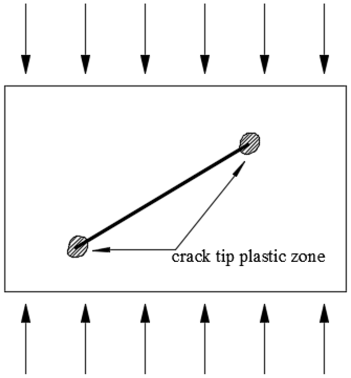
2. Crack Tip Plastic Zone of Rocks

Generally, the ratio of the plastic zone feature size (rp) to the half-length of the crack (a) is used to determine the type of crack tip plastic zone. If this ratio is less than 0.1, the plastic zone type can be called a small-area yield; that is, the plastic zone only appears in the small area at the crack tip [27]. For the small-area yield, the stress intensity factor used in the linear elastic fracture mechanics can also be applied. Here, for simplicity, the research is conducted under the small-area-yield condition.
For the rock, the yield criterion generally used is the M-C yield criterion. However, its yield surface in the π plane is an irregular hexagon. Thus, there are some difficulties with using the M-C yield criterion [28]. To overcome this problem, the generalized D-P yield criterion was developed according to the M-C yield criterion for yield surfaces of irregular hexagons [29], and this yield criterion can be easily applied in engineering computations. Therefore, the generalized D-P yield criterion is used in this study and can be written as follows:
F = α I 1 + J 2 = k ,
where I1 is the first invariant of the stress tensor, J2 is the second invariant of the deviator stress tensor, and α and k are two parameters that are related to the internal frictional angle ( ϕ ) and adhesion ( c ) of rock, which can be described as
α = 2 sin ϕ 3 ( 3 sin ϕ ) ,
k = 6 c cos ϕ 3 ( 3 sin ϕ ) ,
I1 and J2 can be described as follows:
I 1 = σ 1 + σ 2 + σ 3 ,
J 2 = 1 6 σ 1 σ 2 2 + σ 2 σ 3 2 + σ 3 σ 1 2 ,
where σ 1 , σ 2 , and σ 3 are the maximum principal stress, intermediate principal stress, and minimum principal stress, respectively.
Based on fracture mechanics [1], the three principal stresses at the crack tip ( σ 1 , σ 2 , σ 3 ) are as follows:
σ 1 = K I 2 π r [ cos θ 2 λ sin θ 2 + 1 2 sin 2 θ + 2 λ sin 2 θ + λ 2 ( 4 3 sin 2 θ ) σ 2 = K I 2 π r [ cos θ 2 λ sin θ 2 1 2 sin 2 θ + 2 λ sin 2 θ + λ 2 ( 4 3 sin 2 θ ) ] σ 3 = 0 for   plane   stress υ ( σ 1 + σ 2 ) for   plane   strain ,
where υ is Poisson’s ratio, r and θ are the polar coordinates of the principal stress, and λ is described as
λ = K II K I ,
where KI and KII are stress intensity factors of mode I and mode II cracks, respectively.
Equation (6) is substituted into Equations (4) and (5), and the following equations are obtained:
Under the plane stress condition,
I 1 = 2 K I 2 π r ( cos θ 2 λ sin θ 2 ) ,
J 2 = 1 6 K I 2 2 π r 2 R 2 + 3 2 M 2 ,
Under the plane strain condition,
I 1 = 2 K I 2 π r ( 1 + υ ) ( cos θ 2 λ sin θ 2 ) ,
J 2 = 1 6 K I 2 2 π r R 2 1 2 υ 2 + 3 2 M 2 ,
where
R = cos θ 2 λ sin θ 2 ,
M = [ sin 2 θ + 2 λ sin 2 θ + λ 2 ( 4 3 sin 2 θ ) ] 1 2 ,
Equations (8)–(11) are substituted into Equation (1), and the size of the crack tip plastic zone can be obtained as
r = [ 2 α K I π k ( cos θ 2 λ sin θ 2 ) + K I S 2 3 π k ] 2                                   f o r   p l a n e   s t r e s s [ 2 α K I π k ( 1 + υ ) ( cos θ 2 λ sin θ 2 ) + K I T 2 3 π k ] 2         f o r   p l a n e   s t r a i n ,
where
S = 2 cos θ 2 λ sin θ 2 2 + 3 2 sin 2 θ + 2 λ sin 2 θ + λ 2 4 3 sin 2 θ 1 2 2 ,
T = cos θ 2 λ sin θ 2 2 1 2 υ 2 + 3 2 sin 2 θ + 2 λ sin 2 θ + λ 2 4 3 sin 2 θ 1 2 2 ,
From Equation (14), it can be found that the plastic zone size at the crack tip is determined by the yield criterion and the stress intensity factor. To compute the stress intensity factor considering the crack interaction, one typical method is the complex function method. But it is very complex and suitable for complicated problems, such as those considering thermal loading [30,31] and water pressure [32]. Therefore, here, the generally used Kachanov method [33], which is suitable for simple problems, is applied. Although the Kachanov method is proposed for closely spaced cracks in linear elastic materials, in this study, because the small-area-yield condition is applied for the crack tip plastic zone, the computing precision of the Kachanov method is acceptable. Because the traditional Kachanov method is suitable for the interaction between equal-length cracks, here, to consider the interaction of unequal-length cracks in rocks, the improved Kachanov method [34] was applied to compute the stress intensity factor. In this improved Kachanov method, by using the basic principles of the Kachanov method, the pseudo-surface stresses on the crack surfaces for the unequal-length cracks are derived, and the stress intensity factors at the crack tips of two collinear unequal cracks under far-field tension are also derived. When the improved Kachanov method is used for the equal-length cracks, it will transform into the traditional Kachanov method. Therefore, the traditional Kachanov method is only one special case of the improved Kachanov method, and the two methods have the same calculation accuracy. However, the applicability of the improved Kachanov method is wider. More details of the improved Kachanov method can be found in the reference [34].
Due to its low tensile strength, rocks are generally seen as nontensile materials [35]. Thus, in rock mechanics [35], the performance of rocks under compression is the main research object. Moreover, in practical rock engineering, the rock is generally compressed. Therefore, the rock cracks are generally closed cracks, which can only slide along the closed crack surface due to compression. In addition, the cracks always show shear failure, corresponding to mode II cracks.
As shown in Figure 2 (the schematization of the theoretical model), in the rock model, there are two collinear unequal-length cracks.
For this model, it is supposed that the uniform pressure p acts along the vertical direction. The crack angle is γ . The local coordinate systems for cracks 1 and 2 are ( ξ 1 , η 1 ) and ( ξ 2 , η 2 ) , respectively. The global coordinate system of this model is (x, y), whose coordinate origin (o) is at the central point of two cracks. Moreover, in the global coordinate system, the coordinates of the four crack tips (A, B, C, and D) are (−b, 0), (−k, 0), (k, 0), and (c, 0), respectively. The crack lengths are 2a1 and 2a2. Generally, according to the lengths of the cracks, a main crack and a secondary crack can be determined. Therefore, here, for a 1 > a 2 , crack 1 is taken as the main crack, and crack 2 is taken as the secondary crack. It is supposed that the effective normal stress on a crack surface is σ m n i , where i is 1 or 2, and m and n correspond to x and y, respectively. It must be noted that for the stress state on a crack surface, different from the rock, the M-C yield criterion is used to consider the friction effect of the crack surface. For this problem, only normal stress σ y y i and shear stress τ x y i are considered, and the two stresses satisfy the M-C yield criterion. When the crack is active, sliding occurs along the closed crack surface due to compression. Thus, when the crack angle is in the range of 0 to π/2, the following equation is obtained:
τ x y i = τ c + μ σ y y i ,
where τ c is the viscous resistance and μ is the friction coefficient of the crack surface.
According to the superposition principle, if there is only one crack in the infinite plate, the pseudo-surface stress of the crack can be described as
σ y y p i = ( σ y y i σ y y i ) Δ σ y y j i τ x y p i = ( τ x y i τ x y i ) Δ τ x y j i           ( i , j = 1 , 2 , i j ) ,
where σ y y p i and τ x y p i are the pseudo-normal stress and pseudo-shear stress on the surface of crack i. σ y y i and τ x y i are the surface stresses on the surface of crack i due to the far-field pressure. Δ σ y y j i and Δ τ x y j i are the normal stress and shear stress on crack i due to the surface stress of crack j, which are called the crack interaction stresses.
For the closed shear crack, the pseudo-normal stress σ y y p i on the crack surface is zero. Therefore, from Equations (17) and (18), the following equation can be obtained:
τ x y p i = τ c + μ σ y y i τ x y i + μ Δ σ y y j i Δ τ x y j i       i , j = 1 , 2 , i j
The effect coefficients of crack interaction f i j k l ( i , j = 1 , 2 , i j ) are used to compute the crack interaction stress. The effect coefficient of the crack interaction is described as
f i j n n i f i j t n = α j α j ( f ¯ i j n n i f ¯ i j t n ) d ξ j f i j t n i f i j t t = α j α j ( f ¯ i j t n i f ¯ i j t t ) d ξ j ( k , l = n , t ) ,
where
f ¯ i j n n i f ¯ i j t n = a j 2 ξ j 2 2 π G z + G z ¯ + e 2 i α i z z ¯ G z ¯ f ¯ i j t n i f ¯ i j n n = a j 2 ξ j 2 2 π i G z ¯ 1 2 e 2 i α i G z + e 2 i α i z z ¯ G z ¯ ,
where z = z ξ j is the local coordinate of crack j for one point ( ξ j , 0 ) . G(z) and G’(z) can be described as
G z = 1 z ξ j z 2 a j 2 G z = a j 2 + ξ j z 2 z 2 z ξ j 2 z 2 a j 2 3
For collinear cracks, f j i n t = f j i t n = 0 . f j i n t is the tangential stress on crack surface i due to the normal stress on crack surface j, and f j i t n is the normal stress on crack surface i due to the tangential stress on crack surface j. Because the normal stress on the crack surface is zero, Equation (19) can be changed to the following equation:
τ x y p i = τ c + μ σ y y i τ x y i + τ x y p i f j i t t             i , j = 1 , 2 ,   i j ,
Based on the Kachanov method [33], the uniform shear stress on the surface of crack i is
τ x y p i = ( τ c + μ σ y y i τ x y i ) ( 1 + Λ j i t t ) 1 Λ i j t t Λ j i t t ( i , j = 1 , 2 , i j ) ,
where Λ i j k l is the attenuation coefficient of uniform force f i j k l when it is transformed from crack i to crack j, which can be described as
Λ i j k l = 1 2 a i a i a i f i j k l d ξ i ( k , l = n , t ) ,
Based on the above analysis and by the improved Kachanov method [34], the stress intensity factors of the four crack tips (A, B, C, and D) can be obtained as follows:
K I I ( A ) = 2 τ c μ p ( 1 + cos 2 γ ) + p sin 2 γ 2 π a 1 a 1 a 1 a 1 ξ 1 a 1 + ξ 1 1 + 1 + Λ 12 t t 1 Λ 12 t t Λ 21 t t f 21 t t d ξ 1 ,
K I I ( B ) = 2 τ c μ p ( 1 + cos 2 γ ) + p sin 2 γ 2 π a 1 a 1 a 1 a 1 + ξ 1 a 1 ξ 1 1 + 1 + Λ 12 t t 1 Λ 12 t t Λ 21 t t f 21 t t d ξ 1 ,
K I I ( C ) = 2 τ c μ p ( 1 + cos 2 γ ) + p sin 2 γ 2 π a 2 a 1 a 1 a 1 ξ 2 a 1 + ξ 2 1 + 1 + Λ 21 t t 1 Λ 12 t t Λ 21 t t f 12 t t d ξ 2 ,
K I I ( D ) = 2 τ c μ p ( 1 + cos 2 γ ) + p sin 2 γ 2 π a 2 a 1 a 1 a 1 + ξ 1 a 1 ξ 1 1 + 1 + Λ 21 t t 1 Λ 12 t t Λ 21 t t f 12 t t d ξ 2 ,
where a1 and a2 are the half-lengths of cracks 1 and 2, respectively, which are described as
a 1 = b k 2 ,
a 2 = c k 2 ,
f 21 n n ,   f 21 t t ,   f 12 n n ,   f 12 t t ,   Λ 21 n n ,   Λ 21 t t Λ 12 n n ,   Λ 12 t t are the crack interaction coefficients and attenuation coefficients, which can be obtained from Equations (20) and (25) as
f 21 n n = f 21 t t = ξ 1 c + b + 2 k / 2 ξ 1 c + b + 2 k 2 2 c k 2 2 1 ,
f 12 n n = f 12 t t = ξ 2 + c + b + 2 k / 2 ξ 2 + c + b + 2 k 2 2 b k 2 2 1 ,
Λ 21 n n = Λ 21 t t = 1 b k k b 2 b k 2 f 21 n n d ξ 1 = k + b c + b 2 k ( c + d ) b k 1 ,
Λ 12 n n = Λ 12 t t = 1 c k k c 2 c k 2 f 12 n n d ξ 2 = c + b c + k 2 d ( b + k ) c k 1 ,
The obtained stress intensity factors shown in Equations (26)–(29) are substituted into Equation (14), and the sizes of the crack tip plastic zones for two collinear unequal-length cracks can be obtained while considering the crack interaction under uniform pressure. Based on these studies, under the small-area-yield condition, the crack tip plastic zones of adjacent cracks in a rock can be analyzed.
It should be noted that, here, only the performance of rock cracks under compression is studied, which is the main problem of rock mechanics. However, using similar methods, the performance of cracks under tensile stress, which is simpler, can be researched too [36]. That kind of study can be applied to some rocks with special mechanical properties or rock failure problems under specific engineering conditions (such as the existence of tensile stress components).

3. Extension of Crack Tip Plastic Zone Influenced by Crack Spacing

Generally, when the plastic zones between two cracks come into contact, the crack coalescence will occur. The original crack spacing influences crack coalescence. Therefore, the extension of a plastic zone between two cracks influenced by crack spacing is studied here. To determine the maximum far-field uniform pressure, according to Equation (14) and the small-area-yield condition, p D P 3 c can be obtained as
p D P 3 c 0.4 6 cos ϕ ( 3 sin ϕ ) [ sin 2 γ μ ( 1 + cos 2 γ ) ] ,
The left side of Equation (36) is marked as t4(γ, φ′, μ), and the derivative is taken with respect to γ. Thus, the following equation can be obtained as
t 4 ( γ , ϕ , μ ) γ = 0.8 6 cos ϕ ( 3 sin ϕ ) ( cos 2 γ + μ sin 2 γ ) [ sin 2 γ μ ( 1 + cos 2 γ ) ] 2 ,
From Equation (37), when 0 < γ < π/4, for any values of μ, Equation (37) is always less than 0; that is, the function t4(γ, φ′, μ) is a decreasing function. Thus, in this range, p D P 3 c decreases as the crack angle increases. Moreover, when 0 < γ < π/4, the positive and negative properties of Equation (37) are determined by the combined effect of the friction coefficient of the crack surface (μ) and the crack angle (γ). Therefore, the monotonicity of p D P 3 c in this range cannot be determined directly.
To study the development of the crack tip plastic zones between two cracks influenced by crack spacing, two kinds of conditions are considered here: cracks of equal length and cracks of unequal length.

3.1. Study on Equal-Length Cracks

In this study, based on the research experiment, the parameters of the cracks and the rock are assigned as follows. The crack length is 2a = 2.0 m, and the crack angle is π/4. The crack spacing is 2d. For each crack surface, the viscous resistance and the friction coefficient are 0 and 0.3, respectively. The internal frictional angle and adhesion of the rock are φ′ = 30° and c′ = 1.2 MPa. According to Equation (36), p D P 3 c is 1.176. To research the effect of the crack spacing, according to the different ratios of the crack spacing (d) to the crack length (0.16, 0.18, 0.2, 0.3, 0.4, and 0.5), the plastic zone size at the crack tips (B and C) along the crack orientation is analyzed. It must be noted that for equal-length cracks, the plastic zone sizes at the crack tips (B and C) are the same, and thus, only the plastic zone size results at crack tip B are listed in Table 1.
In Table 1, rB is the plastic zone size at crack tip B and Δd is the width of the elastic zone between the two cracks. Notably, if Δd > 0, there is an elastic zone between the crack tips (B and C); that is, the plastic zones are not connected. Otherwise, there is no spacing between the two plastic zones of the crack tips (B and C); that is, the plastic zones have connected, and the two cracks have coalesced.
From Table 1, as d/a decreases from 0.5 to 0.4, Δd/2d decreases by 7.6%. As d/a decreases from 0.4 to 0.3, Δd/2d decreases by 14.44%. In other words, as the crack spacing decreases, the plastic zone width between the two cracks increases, and its increasing extent improves. Moreover, when d/a decreases from 0.3 to 0.2, Δd/2d decreases by 32.75%. However, when d/a ≤ 0.2, the crack tip plastic zone develops very quickly. To further analyze the details of this trend, when d/a is in the small range of 0.2 to 0.1, the development of the crack tip plastic zone is analyzed. As d/a decreases from 0.2 to 0.18 and from 0.18 to 0.16, Δd/2d decreases by 12.2% and 3.15%, respectively. Moreover, when d/a is changed from 0.18 to 0.16, Δd will be a negative number; that is, at that moment, there is no elastic zone between the two cracks, and the plastic zones have connected. Therefore, it can be summarized that as the crack spacing decreases, the plastic zone width between the two cracks greatly increases. When d/a ≤ 0.2, as the crack spacing decreases, the plastic zones will develop very quickly, and the two cracks will interpenetrate. In other words, regarding the influence of crack spacing on the plastic zone development, d/a = 0.2 can be taken as a threshold value. Therefore, d/a ≤ 0.2 can be taken as the basic condition to determine the crack penetration; that is, if this condition is satisfied, the two cracks can be considered one combined crack if the requirement for computing accuracy is not very strict.
The development of the elastic zone between two cracks is shown in Figure 3.
From Figure 3, as the crack spacing decreases, the elastic zone width between the two cracks also decreases, but its decreasing extent enlarges quickly. That is, as the crack spacing decreases, the crack tip plastic zones develop very quickly, and thus, the two cracks propagate quickly. Therefore, the crack spacing seriously affects the development of the crack tip plastic zones. Moreover, the approximate curve of the computed results can be described by a quadratic polynomial function which is as follows:
We = −1.1911s2 + 1.4288s − 0.0849,
where We is the elastic zone width and s is the crack spacing.
For this equation, its correlation coefficient is 0.9981.

3.2. Study on Unequal-Length Cracks

In this study, a2 = 2.0 m and a1 = a2. The other parameters are the same as those in Section 3.1. To study the influence of crack spacing, the plastic zone sizes at the crack tips (B and C) along the crack orientation are researched according to the different ratios of crack spacing (2d) to the secondary crack length, which are 0.22, 0.24, 0.26, 0.3, 0.4, and 0.5. Based on those conditions, the stress intensity factors and plastic zone sizes of the crack tips (B and C) can be obtained (Table 2). The explanations for the parameters in Table 2 are the same as those in Table 1.
From Table 2, when the ratio of the crack spacing to the length of the secondary crack is greater than 0.24, as the crack spacing decreases, the plastic zones of the two cracks further develop, and the rate of growth increases. As d/a2 > 0.3, the elastic zone width between the two cracks increases rapidly. As d/a2 decreases from 0.5 to 0.4 and from 0.4 to 0.3, Δd/2d decreases by 12.79% and 23.83%, respectively. However, when d/a2 ≤ 0.3, the plastic zone sizes at the crack tips increase very quickly. For example, when d/a2 decreases from 0.3 to 0.26, Δd/2d decreases by 16.11%. Moreover, when d/a2 is 0.24 and 0.22, Δd will be negative; that is, at this time, the plastic zones of the two cracks will be connected. Thus, the values of Δd/2d are not reduced according to the same law as for the other crack spacings. Therefore, it can be found that as the crack spacing decreases, the plastic zone widths of the two cracks will greatly increase. When d/a2 ≤ 0.3, as the crack spacing decreases, the plastic zone sizes of the two cracks will increase quickly, and the two cracks will interpenetrate. In other words, for crack spacing to affect plastic zone development, d/a2 = 0.3 can be taken as a threshold value. Therefore, d/a2 ≤ 0.3 can be taken as the basic condition to determine the crack penetration; that is, if this condition is satisfied, the two cracks can be considered one combined crack if the requirement for computing accuracy is not very strict.
The development of the elastic zone between two cracks is shown in Figure 4.
Figure 4 shows that as the crack spacing decreases, the elastic zone width between the two cracks also decreases, but its rate of decrease quickly increases. That is, as the crack spacing decreases, the plastic zones will develop very quickly, and thus, the two cracks propagate quickly. Therefore, the crack spacing seriously affects the development of the crack tip plastic zones. Moreover, the approximate curve of the computed results can be described by a linear function which is as follows:
We = 2.4236s − 0.235,
For this function, its correlation coefficient is 0.9989.
Therefore, the influence of crack spacing on the development of the plastic zones at the crack tips of unequal-length cracks is more serious than that for equal-length cracks.
Based on the studies in the above two sections, the following conclusions can be drawn. For two cracks of equal length, when the ratio of crack spacing to crack length is not larger than 0.2, the increase in the plastic zone size of a crack tip is very fast, and the rate of increase will increase obviously. Therefore, for rock engineering applications, the basic condition for crack coalescence is d/a ≤ 0.2. Moreover, for two cracks of unequal length, when the ratio of crack spacing to secondary crack length is not larger than 0.3, the rate of increase for the plastic zone size of a crack tip will increase obviously. Thus, for rock engineering applications, the basic condition for crack coalescence will be d/a2 ≤ 0.3.

4. Verification Studies

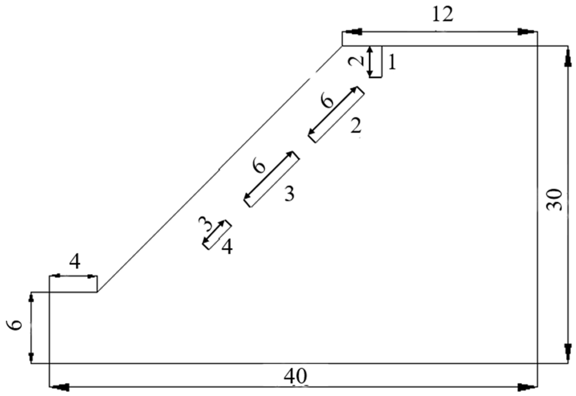
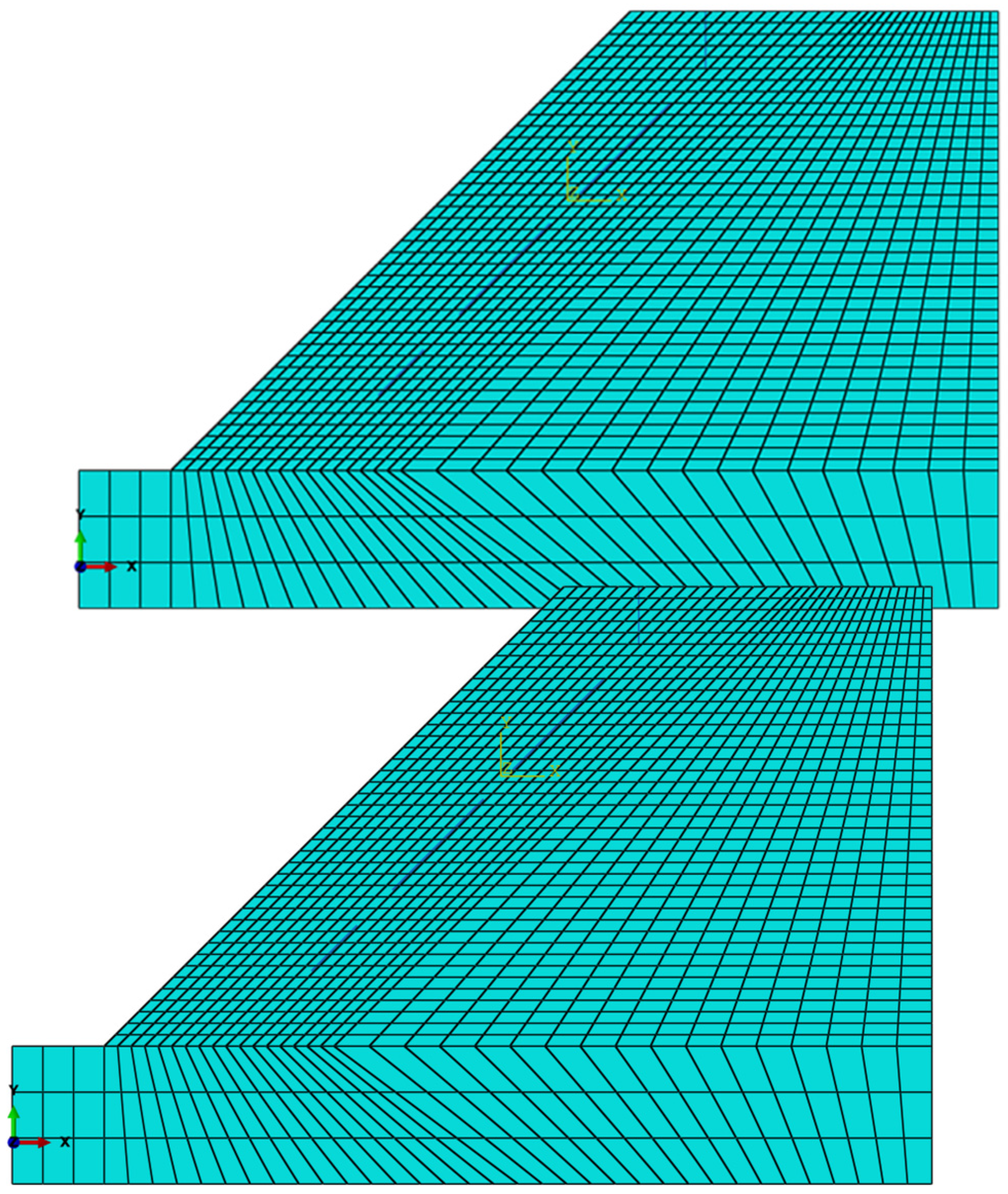
4.1. Numerical Study

To verify the theoretical results about the basic conditions for crack coalescence in Section 3, one rock engineering example is analyzed by XFEM. XFEM is an improved FEM that can simulate crack propagation well [37,38]. This rock engineering example is one rock slope with a height of 24 m and an angle of 45°, as shown in Figure 5.
The material parameters of this rock slope are assigned as summarized in Table 3.
In this rock slope, there are four cracks (Figure 5) whose sizes are summarized in Table 4.
For the four cracks, the lengths of cracks 2 and 3 are the same, which are equal-length cracks. The length of crack 3 is two times the length of crack 4, and thus, they are unequal-length cracks, which is similar to the situation in Section 3.2. From Table 4, the spacing between cracks 2 and 3 and that between cracks 3 and 4 is less than the length of the secondary crack, and thus, for both equal-length and unequal-length cracks, the crack interaction must be considered. It must be noted that crack 1 is under the tensile state; thus, it cannot be considered here. Therefore, in this numerical study, both the equal-length cracks (cracks 2 and 3) and the unequal-length cracks (cracks 3 and 4) are all considered.
In this study, using ABAQUS (Abaqus 6.14) software, the XFEM is applied. The constructed numerical model is shown in Figure 6. In this model, the mesh is refined in the area of the cracks to improve computational accuracy, and thus, the model includes 1471 units and 1552 nodes. Here, the quadrilateral integration unit is used. For this numerical model, the boundary conditions are assigned as follows: a two-direction (x and y) constraint condition is used for the bottom of the model, a one-direction (x) constraint condition is used for the two sides, and other boundaries are free. Moreover, the D-P yield criterion is used in this model.
Although the boundary conditions of this slope case are different from those of the theoretical model in Section 2 (shown in Figure 2), under the small-area-yield condition, that is, the plastic zone appears in only the small area at the crack tip, the increase in the crack tip plastic zone size for this slope case is similar to that of the theoretical model. That is, the development of the crack tip plastic zone is not affected by the boundary conditions under the small-area-yield condition. Therefore, the numerical results can verify the theoretical results well.
Here, the strength reduction method [39] which is a widely used method to analyze the instability process of the slope is used. The computing results are summarized in Figure 7.
It must be noted that for the legend in Figure 7, the PEMAG represents a variable that is the plastic strain magnitude, and it has no unit. The color scale represents the values of the computed plastic strain magnitude. Moreover, Avg is one post-processing algorithm of FEM, which is used to conduct the variable averaging. The default averaging threshold is 75% in the ABAQUS software. That is, when the relative node variable at a node is less than this threshold, the variable result of that node is averaged, where the relative node variable is the ratio of the difference between the maximum value of the node variable and the minimum value of the node variable to the difference between the maximum variable value of all nodes in the region and the minimum variable value of all nodes in the region.
As shown in Figure 7a, when the reduction factor (Fr) is 1.05 (at this time, the computing time is 1.1046 s), at the two tips of crack 3, there are plastic zones that are affected by the two nearby cracks 2 and 4. Moreover, compared with crack 3, crack 4 is the secondary crack. Because the spacing between cracks 3 and 4 is less than the length of crack 4, regarding the influence of crack 3, at the two tips of crack 4, plastic zones will appear. At the same time, regarding the influence of crack 3, there is a plastic zone at the lower tip of crack 2. At this time, the elastic zone width between cracks 2 and 3 is approximately 1.1 m, which is almost 18.33% of the length of crack 2.
As shown in Figure 7b, when the reduction factor increases to 1.08 (the computing time is 1.1418 s), the crack tip plastic zones between cracks 2 and 3 touch, and cracks 2 and 3 coalesce. The time step between this modeling step and the previous one is only 0.0372 s, which is only 3.3% of the total computing time, a small proportion of the total computing time. Thus, this time step is the next step of the above time (1.1046 s). That is, when the ratio of the elastic zone width between cracks 2 and 3 to the length of crack 2 is approximately 0.18, the two cracks coalesce quickly. Based on theoretical studies, d/a ≤ 0.2 is the basic condition for crack coalescence. For the numerical model, this value is 0.18. Therefore, the result of this numerical study agrees well with that of the theoretical study. Moreover, at this time, the elastic zone width between cracks 3 and 4 is approximately 0.83 m, which is almost 27.67% of the length of crack 4. Thus, the value of d/a2 is approximately 0.28.
When the reduction factor increases to 1.12 (shown in Figure 7c; the computing time is 1.1743 s), the crack tip plastic zones between cracks 3 and 4 touch, and cracks 3 and 4 coalesce. The time interval between this modeling step and the previous one is only 0.0325 s, which is only 2.7% of the total computing time. And, this time step is the next step of the above time (1.1418 s). Therefore, the following conclusion can be drawn: when the value of d/a2 is approximately 0.28, the two cracks coalesce quickly. From the theoretical study, the basic condition for crack coalescence is d/a2 ≤ 0.3. Thus, the result of this numerical study can verify the conclusion of the theoretical study well.
Therefore, based on the numerical study, the main conclusions of the theoretical studies can be verified well.
It must be noted that if the situation of cracks is the same, under the small-area-yield condition, the numerical model does not affect the basic condition to determine the crack penetration proposed in the theoretical study. Moreover, to study two different cases of unequal-length cracks and equal-length cracks at the same time, one slope model including two types of cracks whose distributions are the same as those in the theoretical model is applied.

4.2. Experimental Study

In a previous study [40], to study the extension of two collinear cracks of unequal length in rocks by compression, one laboratory test was conducted. In this test, the rock-like specimen is a square cuboid with dimensions of 110 mm × 110 mm × 30 mm. There are two preexisting cracks in the specimen, whose lengths are 24 mm and 12 mm, and their widths are 0.5 mm. The crack angle is 45°, and their spacing is 6 mm. The specimen is shown in Figure 8. Here, the acoustic emission method is used to identify the plastic zone at the crack tip.
For the uniaxial compression test, the process of crack initiation, propagation, and coalescence is shown in Figure 9.
From Figure 9a, during crack initiation, plastic zones appear at the crack tips and can be called shearing cracks in traditional fracture mechanics. The spacing between the plastic zones for the two cracks is approximately 3.5 mm, which is approximately 0.29 times the length of the secondary crack. As the compressive load increases, the plastic zone size of the crack tip increases rapidly, and the rock bridge between the crack tip plastic zones of the two cracks fails. Thus, the two cracks coalesce. At this time, some wing cracks develop near the upper tip of the secondary crack and the lower tip of the main crack, which is shown in Figure 9b.
Therefore, based on the experimental results, for crack initiation, wing cracks appear at the crack tips, which are the new crack tips, and thus, the crack spacing is reduced. For the stress concentration at the crack tip, a new plastic zone will appear at the new crack tip. In other words, the plastic zone size will increase with crack propagation. At that time, the increase in the plastic zone size is relatively slow. When the crack spacing is reduced to 0.29 times the length of the secondary crack, the two cracks coalesce very quickly. Because the experimental material is not an ideal homogeneous material and contains many initial defects, it is different from the material used in the theoretical study. Due to the initial defects in the experimental material, the test specimen will be fractured more easily. Therefore, the ultimate crack spacing for crack coalescence obtained by the laboratory test is less than that obtained by the theoretical study (0.3 times the length of the secondary crack). For the small difference between the laboratory test and theoretical study results, which is only 0.01, the theoretical work can be well verified by the laboratory test.

5. Conclusions

In this study, by using the generalized D-P yield criterion, the plastic zone development at a rock crack tip was researched by considering the interaction of two collinear cracks. The basic theory of the improved Kachanov method was applied to analyze the interaction of two cracks for two conditions (plane stress and plane strain). Moreover, the influence of the crack spacing on the plastic zone development at the crack tip was analyzed. Finally, by using a numerical study on a rock slope including four preexisting cracks of equal length or unequal length by the XFEM and a laboratory test for a rock-like sample with two cracks of unequal length, the main conclusions of the theoretical studies were verified. From these studies, the main conclusions drawn were as follows:
(1)
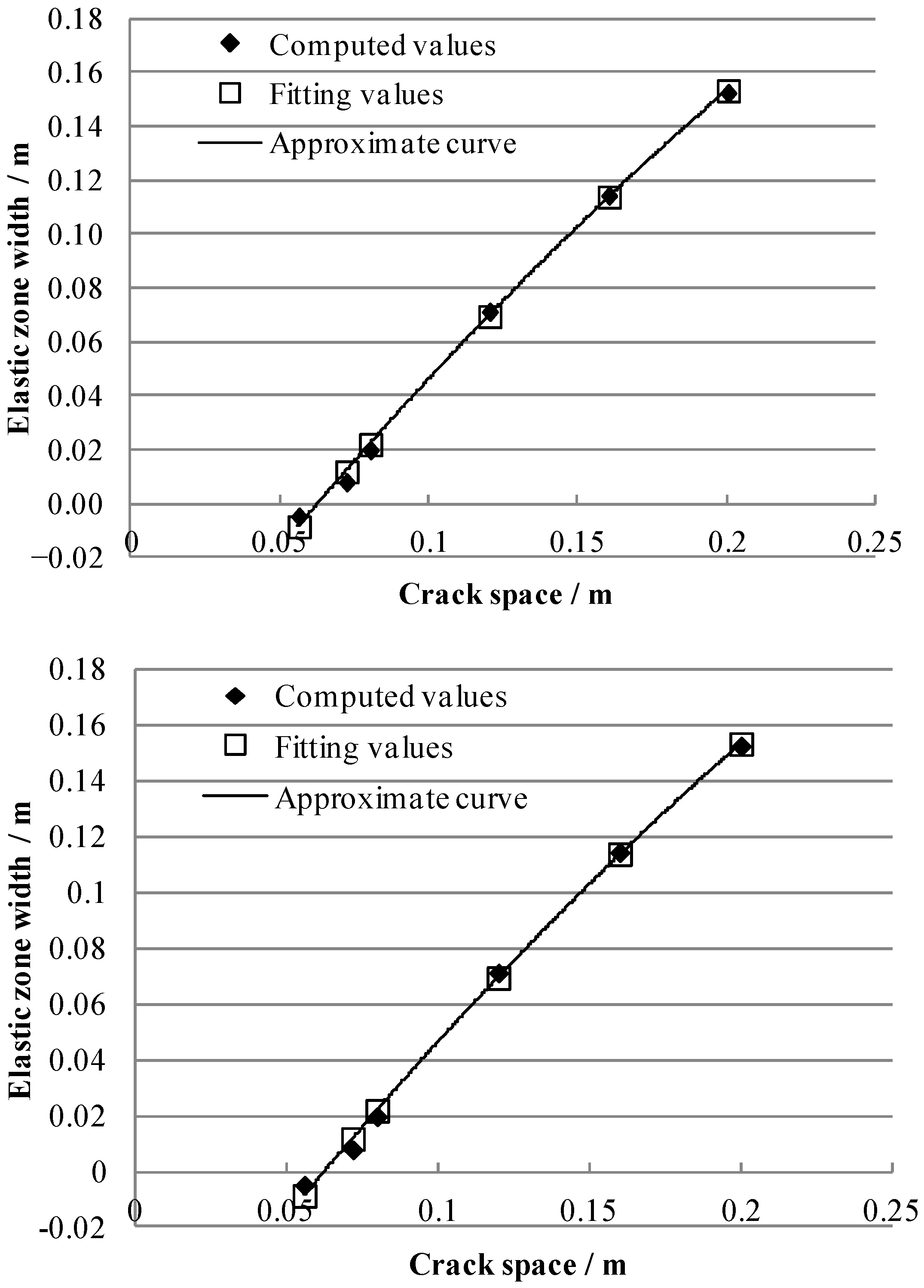
For two cracks of equal length, as the crack spacing decreases, the plastic zones at the two crack tips develop very quickly, and the cracks extend quickly. Moreover, one quadratic polynomial function can be used to describe the relationship between the elastic zone width between two cracks and the crack spacing.
(2)
For two cracks of equal length, the threshold value of crack spacing can be represented by the ratio of crack spacing to crack length of 0.2. Therefore, the ratio of crack spacing to crack length of 0.2 can be taken as the basic condition to determine the crack penetration; that is, if this ratio is equal to or less than 0.2, the two cracks can be considered one combined crack if the requirement for computing accuracy is not very strict.
(3)
For two cracks of unequal length, as the crack spacing decreases, the plastic zones at the crack tips develop very quickly, and the cracks extend quickly. Moreover, one linear function can be used to describe the relationship between the elastic zone width between two cracks and the crack spacing.
(4)
For two cracks of unequal length, the threshold value of crack spacing can be represented by the ratio of crack spacing to secondary crack length of 0.3. Therefore, the ratio of crack spacing to secondary crack length of 0.3 can be taken as the basic condition to determine the crack penetration; that is, if this ratio is equal to or less than 0.3, the two cracks can be considered one combined crack if the requirement for computing accuracy is not very strict.
It must be noted that the conclusions of this theoretical study can be used for practical rock engineering. If the fractures in the rock engineering have similar distributions as the theoretical model and their development can be monitored in the field measurement, the main conclusions of this theoretical study can be used to determine the threshold time of engineering instability and provide a suitable time for the engineering reinforcement.
Lastly, notably, with this theoretical method, the computed plastic zone has a regular shape. However, for real rocks, due to heterogeneity, the real plastic zone does not have a regular shape. Moreover, real crack morphology is relatively complicated. Therefore, theoretical methods are used to only approximately describe the plastic zone of the crack tip in rocks. This is a limitation of the abovementioned theoretical studies.

Author Contributions

Conceptualization, X.Z. and W.G.; methodology, W.G.; software, X.W.; validation, X.C. and X.W.; formal analysis, X.Z. and X.W.; investigation, X.C.; resources, X.Z.; writing—original draft preparation, X.C. and X.W.; writing—review and editing, W.G.; visualization, X.W.; supervision, W.G.; project administration, X.Z. All authors have read and agreed to the published version of the manuscript.

Funding

This research received no external funding.

Data Availability Statement

No new data were created or analyzed in this study. Data sharing is not applicable to this article.

Conflicts of Interest

The authors declare no conflicts of interest.

References

  1. Gross, D.; Seelig, T. Fracture Mechanics; Springer: Heidelberg/Berlin, Germany, 2011. [Google Scholar]
  2. Rossmanith, H. Rock Fracture Mechanics; Springer: Heidelberg/Berlin, Germany, 1983. [Google Scholar]
  3. Cao, P.; Liu, T.Y.; Pu, C.Z.; Lin, H. Crack propagation and coalescence of brittle rock-like specimens with pre-existing cracks in compression. Eng. Geol. 2015, 187, 113–121. [Google Scholar] [CrossRef]
  4. Huang, D.; Gu, D.M.; Yang, C.; Huang, R.Q.; Fu, G.Y. Investigation on Mechanical Behaviors of Sandstone with Two Preexisting Flaws under Triaxial Compression. Rock Mech. Rock Eng. 2016, 49, 375–399. [Google Scholar] [CrossRef]
  5. Luo, Y.; Ren, L.; Xie, L.Z.; Ai, T.; He, B. Fracture Behavior Investigation of a Typical Sandstone Under Mixed-Mode I/II Loading Using the Notched Deep Beam Bending Method. Rock Mech. Rock Eng. 2017, 50, 1987–2005. [Google Scholar] [CrossRef]
  6. Zhao, C.; Zhou, Y.M.; Zhao, C.F.; Bao, C. Cracking Processes and Coalescence Modes in Rock-Like Specimens with Two Parallel Pre-existing Cracks. Rock Mech. Rock Eng. 2018, 51, 3377–3393. [Google Scholar] [CrossRef]
  7. Sivakumar, G.; Maji, V.B. A Study on Crack Initiation and Propagation in Rock with Pre-existing Flaw under Uniaxial Compression. Indian Geotech. J. 2018, 48, 626–639. [Google Scholar] [CrossRef]
  8. Wang, H.Y. Poro-elasto-plastic modeling of complex hydraulic fracture propagation: Simultaneous multi-fracturing and producing well interference. Acta Mech. 2016, 227, 507–525. [Google Scholar] [CrossRef]
  9. Wu, Z.J.; Wong, L.N.Y. Elastic–plastic cracking analysis for brittle–ductile rocks using manifold method. Int. J. Fract. 2013, 180, 71–91. [Google Scholar] [CrossRef]
  10. Fakhimi, A.; Wan, F. Discrete element modeling of the process zone shape in mode I fracture at peak load and in post-peak regime. Int. J. Rock Mech. Min. Sci. 2016, 85, 119–128. [Google Scholar] [CrossRef]
  11. Funatsu, T.; Shimizu, N.; Kuruppu, M.; Matsui, K. Evaluation of Mode I Fracture Toughness Assisted by the Numerical Determination of K-Resistance. Rock Mech. Rock Eng. 2015, 48, 143–157. [Google Scholar] [CrossRef]
  12. Tarokh, A.; Makhnenko, R.Y.; Fakhimi, A.; Labuz, J.F. Scaling of the fracture process zone in rock. Int. J. Fract. 2017, 204, 191–204. [Google Scholar] [CrossRef]
  13. Wei, M.D.; Dai, F.; Xu, N.W.; Zhao, T.; Xia, K.W. Experimental and numerical study on the fracture process zone and fracture toughness determination for ISRM-suggested semi-circular bend rock specimen. Eng. Fract. Mech. 2016, 154, 43–56. [Google Scholar] [CrossRef]
  14. Wei, M.D.; Dai, F.; Xu, N.W.; Zhao, T. Stress intensity factors and fracture process zones of ISRM-suggested chevron notched specimens for mode I fracture toughness testing of rocks. Eng. Fract. Mech. 2016, 168, 174–189. [Google Scholar] [CrossRef]
  15. Galouei, M.; Fakhimi, A. Size effect, material ductility and shape of fracture process zone in quasi-brittle materials. Comput. Geotech. 2015, 65, 126–135. [Google Scholar] [CrossRef]
  16. Wu, Z.J.; Ma, L.L.; Fan, L.F. Investigation of the characteristics of rock fracture process zone using coupled FEM/DEM method. Eng. Fract. Mech. 2018, 200, 355–374. [Google Scholar] [CrossRef]
  17. Wu, H.J.; Wang, Z.C.; Wang, C. The Mechanism Study of Cracks Propagation of Different Floor Strata Combinations Under Mining. Geotech. Geol. Eng. 2018, 36, 3743–3749. [Google Scholar] [CrossRef]
  18. Papanastasiou, P.; Durban, D. The Influence of Crack-Face Normal and Shear Stress Loading on Hydraulic Fracture-Tip Singular Plastic Fields. Rock Mech. Rock Eng. 2018, 51, 3191–3203. [Google Scholar] [CrossRef]
  19. Papanastasiou, P.; Atkinson, C. Representation of crack-tip plasticity in pressure sensitive geomaterials. Int. J. Fract. 2000, 102, 271–286. [Google Scholar] [CrossRef]
  20. Ai, T.; Wu, C.H.; Zhang, R.; Xiang, Z.Y.; Yuan, Y.Y.; Wang, S.Y. On the Plastic Zone around a Crack Tip in a Rock Specimen. In Proceedings of the 2nd International Conference on Electronic & Mechanical Engineering and Information Technology, Shenyang, China, 7 September 2012; Atlantis Press: Paris, France; pp. 683–686. [Google Scholar]
  21. Brooks, Z.; Ulm, F.J.; Einstein, H.H. Environmental scanning electron microscopy (ESEM) and nanoindentation investigation of the crack tip process zone in marble. Acta Geotech. 2013, 8, 223–245. [Google Scholar] [CrossRef]
  22. Erarslan, N. Microstructural investigation of subcritical crack propagation and Fracture Process Zone (FPZ) by the reduction of rock fracture toughness under cyclic loading. Eng. Geol. 2016, 208, 181–190. [Google Scholar] [CrossRef]
  23. Dutler, N.; Nejati, M.; Valley, B.; Amann, F.; Molinari, G. On the link between fracture toughness, tensile strength, and fracture process zone in anisotropic rocks. Eng. Fract. Mech. 2018, 201, 56–79. [Google Scholar] [CrossRef]
  24. Zietlow, W.K.; Labuz, J.F. Measurement of the intrinsic process zone in rock using acoustic emission. Int. J. Rock Mech. Min. Sci. 1998, 35, 291–299. [Google Scholar] [CrossRef]
  25. Vavroa, L.; Součeka, K.; Kytýřb, D.; Fílab, T.; Keršnerc, Z.; Vavroa, M. Visualization of the Evolution of the Fracture Process Zone in Sandstone by Transmission Computed Radiography. Procedia Eng. 2017, 191, 689–696. [Google Scholar] [CrossRef]
  26. Ghamgosar, M.; Erarslan, N.; Williams, D.J. Experimental Investigation of Fracture Process Zone in Rocks Damaged Under Cyclic Loadings. Exp. Mech. 2017, 57, 97–113. [Google Scholar] [CrossRef]
  27. Maji, V.B.; Sivakumar, G. Crack Initiation-Propagation and Failure Modes in Rocks. In Geotechnics for Natural and Engineered Sustainable Technologies, Developments in Geotechnical Engineering; Krishna, A.M., Ed.; Springer: Singapore, 2018; pp. 317–328. [Google Scholar]
  28. Teruo, N. Constitutive Modeling of Geomaterials: Principles and Applications; CRC Press: Boca Raton, FL, USA, 2012. [Google Scholar]
  29. Zheng, Y.R.; Kong, L. Geotechnical Plastic Mechanics; China Architecture & Building Press: Beijing, China, 2019. [Google Scholar]
  30. Zhang, Q.Q.; Song, H.P.; Gao, C.F. The intrinsic relationship of the thermal stress intensity factor and the temperature difference at the crack surface. J. Therm. Stress. 2024, 47, 897–908. [Google Scholar] [CrossRef]
  31. Song, H.P.; Xie, K.K.; Gao, C.F. Temperature, thermal flux and thermal stress distribution around an elliptic cavity with temperature-dependent material properties. Int. J. Solids Struct. 2021, 216, 136–144. [Google Scholar]
  32. Gao, W.; Yuan, S.; Ge, S.S.; Zhao, Z.H.; Han, Y. Theoretical study on the stress intensity factor at the crack tip of a water-bearing rock. Appl. Math. Model. 2025, 142, 115976. [Google Scholar] [CrossRef]
  33. Kachanov, M. Elastic solids with many cracks: A simple method of analysis. Int. J. Solids Struct. 1987, 23, 23–43. [Google Scholar] [CrossRef]
  34. Xi, J.Y.; Chen, Z.H.; Zhang, W. Fracture Mechanics Analysis of Unequal Cracks Interaction under Uniaxial Tension. Chin. J. Rock Mech. Eng. 2014, 33 (Suppl. S2), 3625–3630. [Google Scholar]
  35. Jaeger, J.C.; Cook, N.G.W.; Zimmerman, R.W. Fundamentals of Rock Mechanics; Blackwell Publishing: Malden, MA, USA, 2017. [Google Scholar]
  36. Gao, W.; Xiao, T.; Wang, X.; Wang, C. Theoretical study on extension of crack tip plastic zone by remote simple tensile considering crack interaction. Eur. J. Mech. A-Solid. 2019, 77, 103814. [Google Scholar] [CrossRef]
  37. Belytschko, T.; Moes, N.; Usui, S.; Parimik, C. Arbitrary discontinuities in finite elements. Int. J. Numer. Meth. Eng. 2001, 50, 993–1013. [Google Scholar] [CrossRef]
  38. Stolarska, M.; Chopp, D.L.; Moes, N.; Belyschko, T. Modeling crack growth by level sets in the extended finite element method. Int. J. Numer. Meth. Eng. 2001, 51, 943–960. [Google Scholar] [CrossRef]
  39. Dawson, E.M.; Roth, W.H.; Drescher, A. Slope stability analysis by strength reduction. Géotechnique 1999, 49, 835–840. [Google Scholar] [CrossRef]
  40. Xi, J.Y. Interaction and Propagation Research of the Cracks with Unequal Length in Cement Brittle Materials. Ph.D. Thesis, China University of Mining & Technology (Beijing), Beijing, China, 2015. [Google Scholar]
Figure 1. Plastic zones at the crack tips.
Mathematics 13 00718 g001
Figure 2. Computation model for two collinear unequal-length cracks in rock.
Mathematics 13 00718 g002
Figure 3. Development of the elastic zone between two equal-length cracks.
Mathematics 13 00718 g003
Figure 4. Development of the elastic zone between two unequal-length cracks.
Mathematics 13 00718 g004
Figure 5. Rock slope example.
Mathematics 13 00718 g005
Figure 6. Numerical model of the rock slope.
Mathematics 13 00718 g006
Figure 7. Computational plastic zone of the rock slope: (a) Fr is 1.05; (b) Fr is 1.08; (c) Fr is 1.12.
Mathematics 13 00718 g007
Figure 8. Testing specimen.
Mathematics 13 00718 g008
Figure 9. Expansion process of cracks during the uniaxial compression test: (a) crack initiation; (b) crack propagation.
Mathematics 13 00718 g009
Table 1. Plastic zone size for different crack spacing of equal cracks.
d/arB/m Δ d /m Δ d /2d/%
0.160.0789−0.00486.46
0.180.07460.00799.61
0.20.07110.019821.81
0.30.05930.071254.56
0.40.05230.114368.60
0.50.04760.152476.20
Table 2. Plastic zone size according to crack spacing for unequal cracks.
d/a2rB/mrC/m Δ d /m
0.220.11550.0865−0.0260
0.240.11240.0830−0.0034
0.260.10970.07990.0184
0.30.10520.07490.0599
0.40.09770.06620.1561
0.50.09300.06060.2463
Table 3. Material parameters of rock slope.
ParameterYoung’s Modulus/GPaPoisson’s RatioInternal Frictional Angle/DegreeAdhesion/MPaTensile Strength/MPaUnit Weight/kN/m3
Value12.20.28301.2424.1
Table 4. Sizes of four cracks.
NumberDip Angle/DegreeLength/mDistance/m
19020
24562.4
34562
44532.2
Disclaimer/Publisher’s Note: The statements, opinions and data contained in all publications are solely those of the individual author(s) and contributor(s) and not of MDPI and/or the editor(s). MDPI and/or the editor(s) disclaim responsibility for any injury to people or property resulting from any ideas, methods, instructions or products referred to in the content.

