
Implementation of Constant Power Control for a Reamer Using a Fuzzy PID Algorithm

Abstract
1. Introduction
2. Mathematical Development
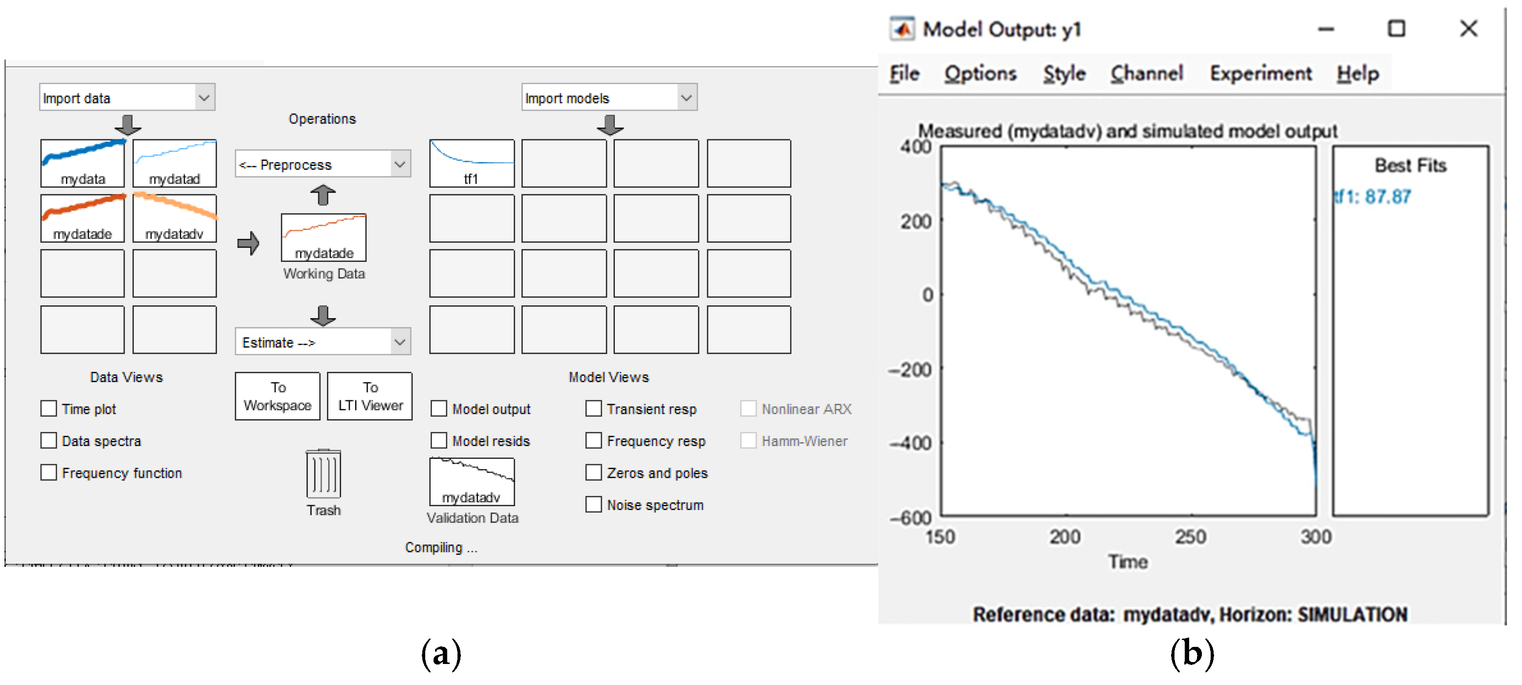
3. Simulation Model Construction
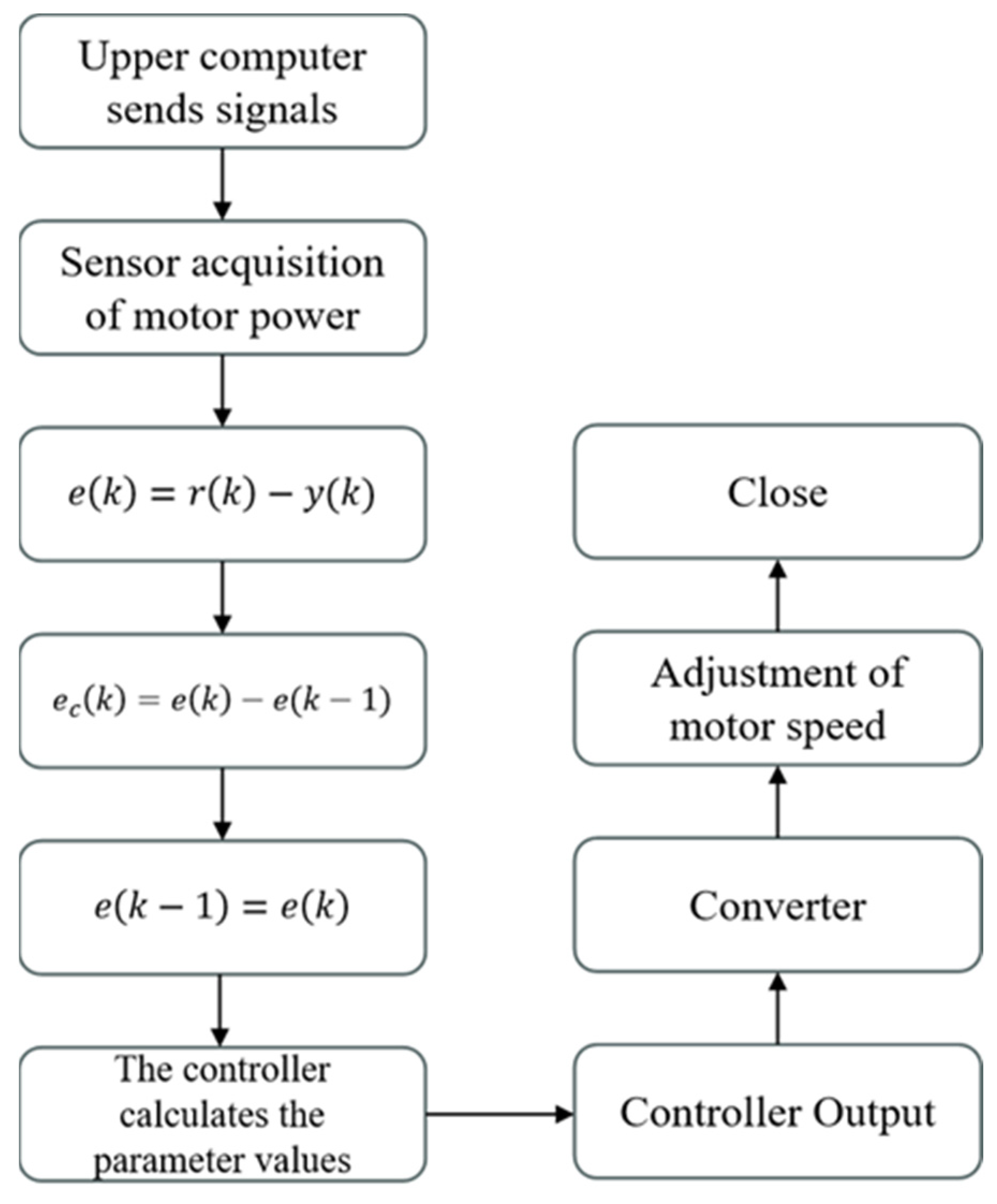
3.1. Traditional PID Model
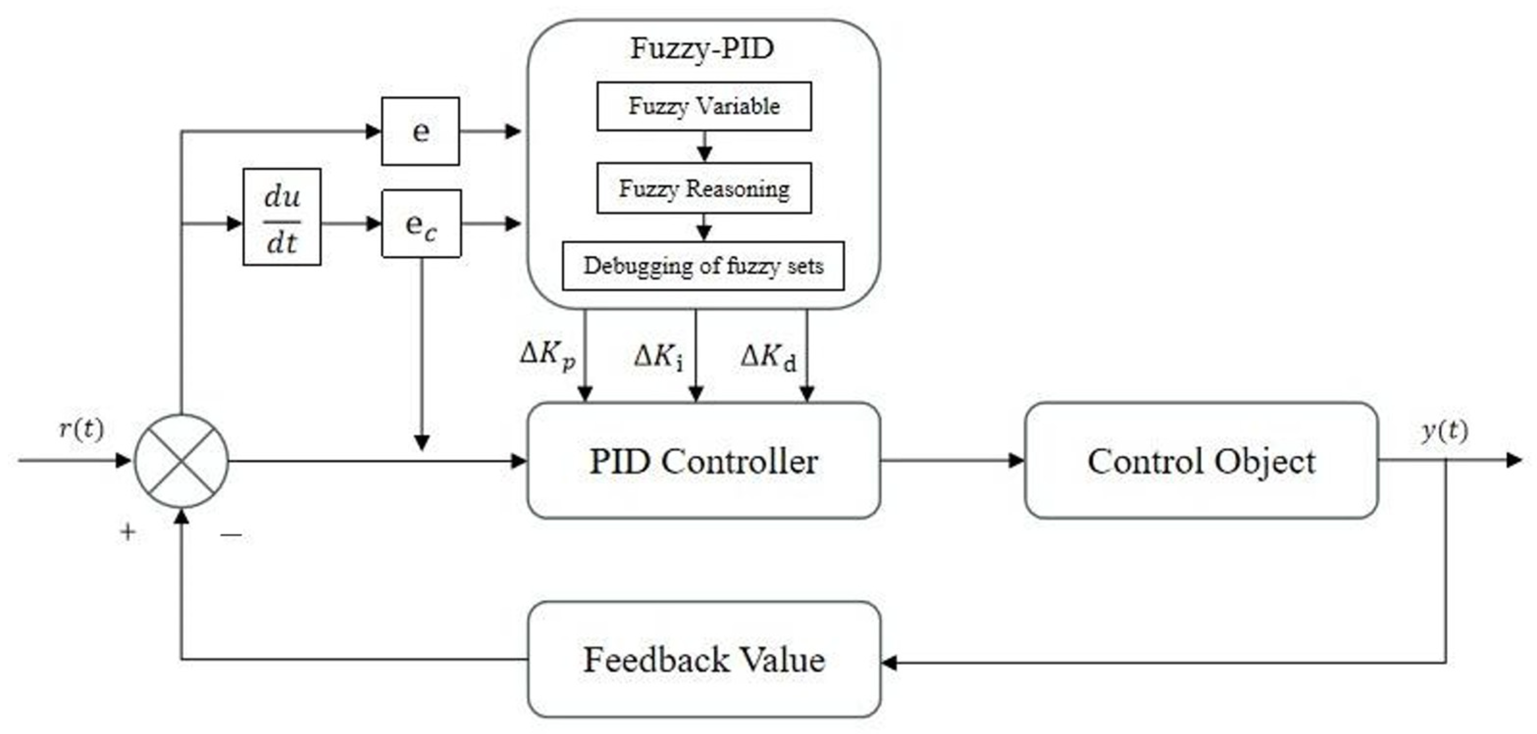
3.2. Fuzzy PID Control
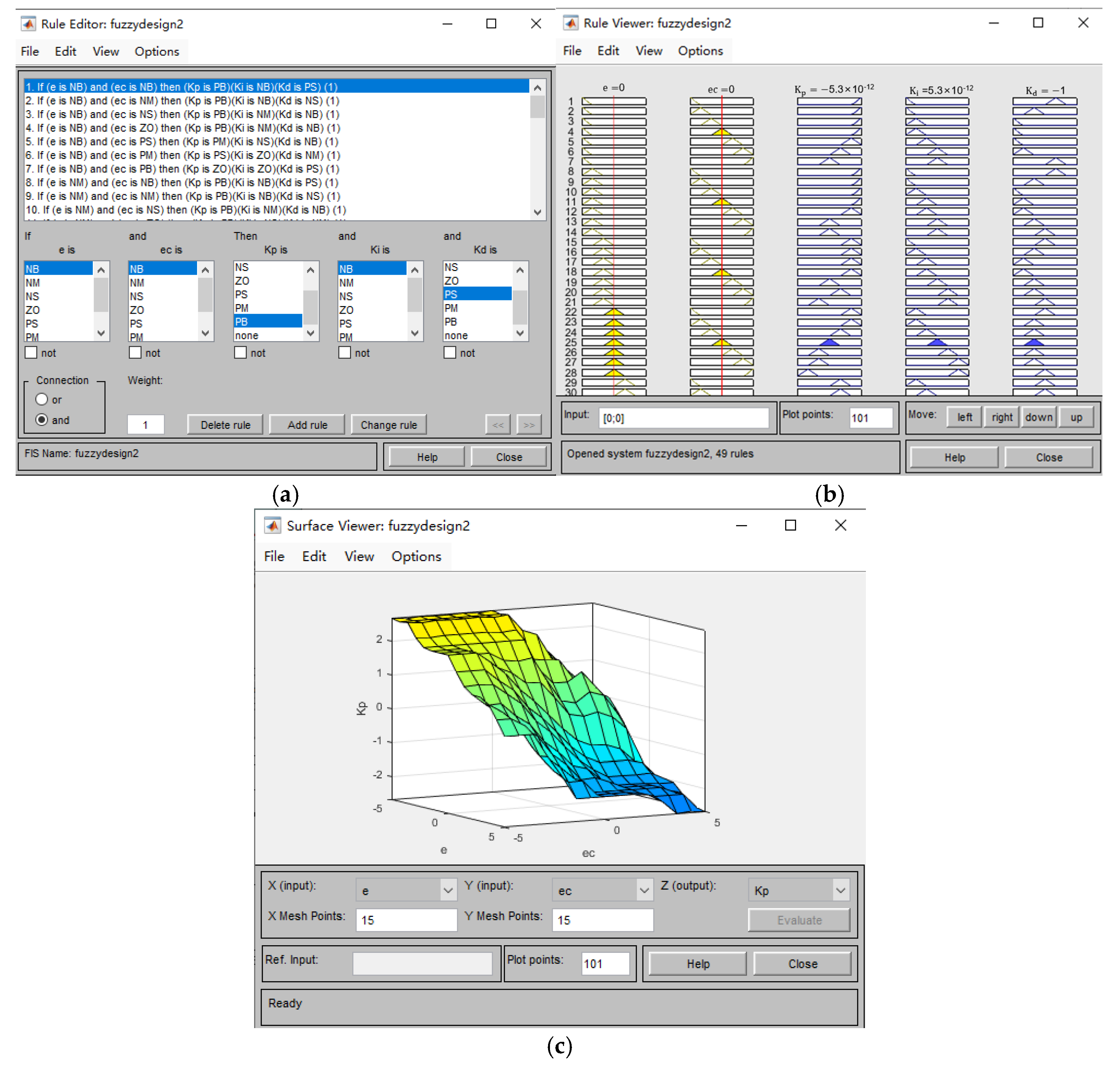
- The structure of the fuzzy controller is determined and input and output fuzzification is performed.
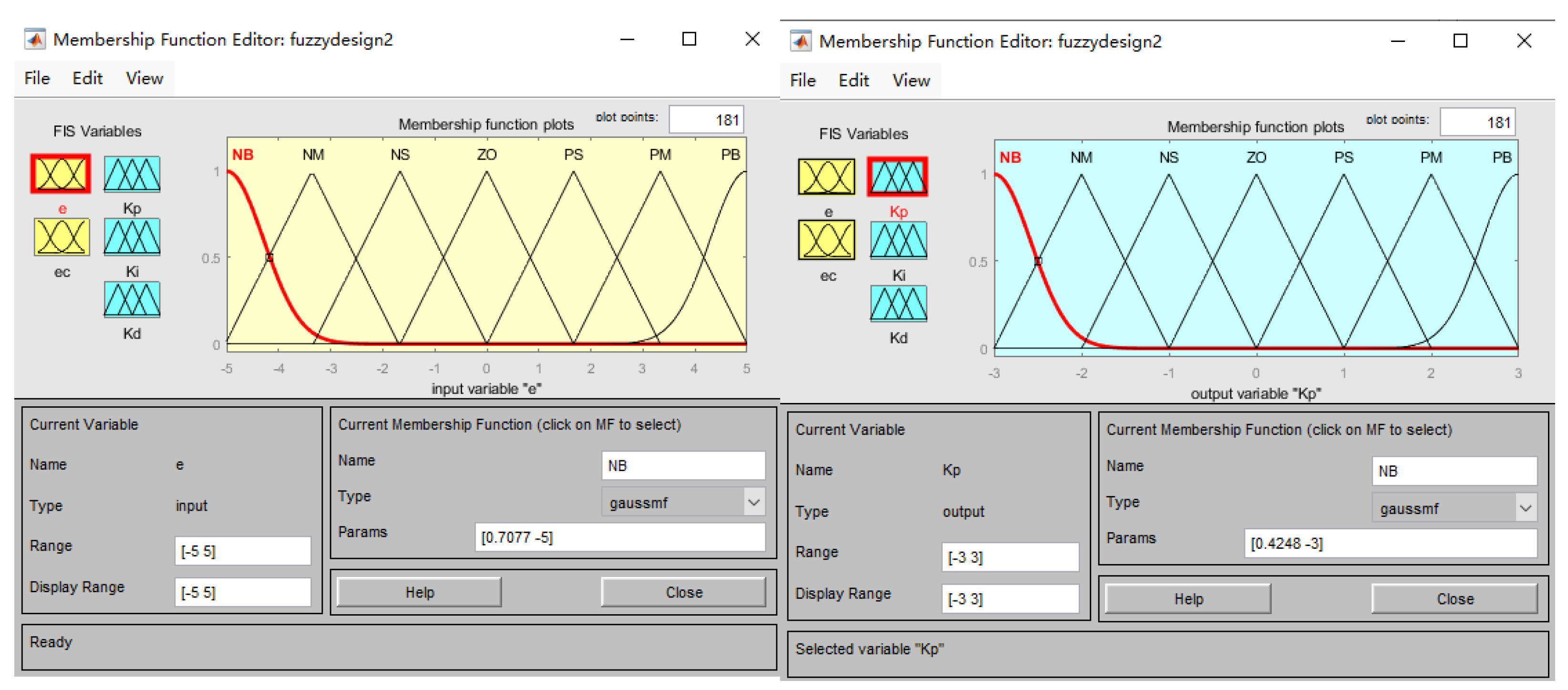
- The inputs are the deviation, , which represents the difference between the implemented motor power and the system-set power value , and the rate of change in this deviation, . The outputs are the parameter values that need to be adjusted, making the controller a two-input, three-output structure. The fuzzy controller is designed within the MATLAB environment, as shown in Figure 5.
4. Experimental Verification
4.1. Experimental Platform Construction
4.2. Experimental Results
5. Conclusions
Author Contributions
Funding
Data Availability Statement
Conflicts of Interest
References
- Tang, J.Z. Research on the Optimization and Control of Dredging Operation of Stranded Suction Dredger. Ph.D. Thesis, Zhejiang University, Hangzhou, China, 2007. [Google Scholar]
- Zheng, L. Application of PLC in control system of small and medium-sized dredger. Electr. Times 2013, 7, 104–105. [Google Scholar]
- Zhou, X.; Huang, T.; Ma, Y.; Gao, Z. The research on system of frequency conversion and speed regulation of exchange asynchronous motor. In Proceedings of the 2017 IEEE International Conference on Mechatronics and Automation (ICMA), Takamatsu, Japan, 6–9 August 2017; IEEE: New York, NY, USA, 2017; pp. 1–6. [Google Scholar]
- Zhou, J.; Tan, X.L.; Wang, W.B. Research of Control System of Variable Frequency Motor. Appl. Mech. Mater. 2014, 556, 2244–2247. [Google Scholar] [CrossRef]
- Hong, B.; Fu, Z.Y.; Du, J. The application of speeder based on frequency conversion and fluid viscous soft start in port. Appl. Mech. Mater. 2013, 373, 167–170. [Google Scholar] [CrossRef]
- Liu, Y.; Xue, S. Study on Hoisting Speed Control for the 7500T Full Revolving Floating Crane. In Proceedings of the 2009 International Conference on Measuring Technology and Mechatronics Automation, Zhangjiajie, China, 11–12 April 2009; IEEE: New York, NY, USA, 2009; Volume 1, pp. 886–889. [Google Scholar]
- Manuelle, P.; Singam, B.; Siala, S. Induction motors fed by PWM MV7000 converters enhance electric propulsion performance. In Proceedings of the 2009 13th European Conference on Power Electronics and Applications, Barcelona, Spain, 8–10 September 2009; IEEE: New York, NY, USA, 2009; pp. 1–9. [Google Scholar]
- Tang, J.; Wang, Q.; Zhong, T. Automatic monitoring and control of cutter suction dredger. Autom. Constr. 2009, 18, 194–203. [Google Scholar] [CrossRef]
- Luan, J.; Yu, M.; Yuan, W. Research on power distribution control strategy cutter suction dredger. In Proceedings of the 2020 Chinese Automation Congress (CAC 2020), Shanghai, China, 6–8 November 2020; pp. 945–950. [Google Scholar]
- Jingqing, D.; Shiqiao, G.; Chuang, L.; Haipeng, L. An improved control method based on PID algorithm. In Proceedings of the 2010 2nd International Conference on Advanced Computer Control, Shenyang, China, 27–29 March 2010; pp. 124–129. [Google Scholar]
- Sengupta, A.; Das, D.K. Delay dependent wide area damping controller design for a linear parameter varying (LPV) power system model considering actuator saturation and changing environmental condition. Sādhanā 2022, 47, 78. [Google Scholar] [CrossRef]
- Deepika, D.; Singh, N. Exponential state observer based finite time control of fully active hybrid energy storage system. Sādhanā 2022, 47, 21. [Google Scholar] [CrossRef]
- Khan, M.A.; Haque, A.; Kurukuru, V.S.B.; Blaabjerg, F. Optimizing the Performance of Single-Phase Photovoltaic Converter using Wavelet-Fuzzy Controller. e-Prime-Adv. Electr. Eng. Electron. Energy 2023, 3, 100093. [Google Scholar] [CrossRef]
- García-Triviño, P.; Sarrias-Mena, R.; García-Vázquez, C.A.; Leva, S.; Fernández-Ramírez, L.M. Optimal online battery power control of grid-connected energy-stored quasi-impedance source converter with PV system. Appl. Energy 2023, 329, 120286. [Google Scholar] [CrossRef]
- Long, B.; Li, X.Y.; Rodriguez, J.; Chong, K.T. Frequency stability enhancement of an islanded microgrid: A fractional-order virtual synchronous generator. Int. J. Electr. Power Energy Syst. 2023, 147, 108896. [Google Scholar] [CrossRef]
- Tamir, T.S.; Xiong, G.; Shen, Z.; Gong, X.; Liu, S.; Lodhi, E.; Wan, L.; Dong, X. Comparative study of four speed controllers of brushless DC motors for industrial applications. Ifac-PapersOnline 2020, 53, 59–64. [Google Scholar] [CrossRef]
- Shyam, A.; JL, F.D. A comparative study on the speed response of BLDC motor using conventional PI controller, anti-windup PI controller and fuzzy controller. In Proceedings of the 2013 International Conference on Control Communication and Computing (ICCC), Thiruvananthapuram, India, 13–15 December 2013; IEEE: New York, NY, USA, 2013; pp. 68–73. [Google Scholar]
- Yin, H.; Yi, W.; Wu, J.; Wang, K.; Guan, J. Adaptive fuzzy neural network PID algorithm for BLDCM speed control system. Mathematics 2021, 10, 118. [Google Scholar] [CrossRef]
- Liu, Q.X. Design of flow control system based on expert PID. In Proceedings of the 2016 International Symposium on Computer, Consumer and Control (IS3C), Xi’an, China, 4–6 July 2016; pp. 1031–1034. [Google Scholar]
- Maraba, V.A.; Kuzucuoglu, A.E. PID neural network based speed control of asynchronous motor using programmable logic controller. Adv. Electr. Comput. Eng. 2011, 11, 23–28. [Google Scholar] [CrossRef]
- Howimanporn, S.; Chookaew, S.; Sootkaneung, W. Implementation of PSO based gain-scheduled PID and LQR for DC motor control using PLC and SCADA. In Proceedings of the 2018 International Conference on Control and Robots (ICCR), Hong Kong, China, 15–17 September 2018; pp. 52–56. [Google Scholar]
- Sangeetha, A.L.; Naveenkumar, B.; Ganesh, A.B.; Bharathi, N. Experimental validation of PID based cascade control system through SCADA-PLC-OPC and internet architectures. Measurement 2012, 45, 643–649. [Google Scholar] [CrossRef]
- Kroičs, K.; Būmanis, A. BLDC Motor Speed Control with Digital Adaptive PID-Fuzzy Controller and Reduced Harmonic Content. Energies 2024, 17, 1311. [Google Scholar] [CrossRef]
- Ma, C.; Huang, B.; Basher, M.K.; Rob, M.A.; Jiang, Y. Fuzzy PID Control Design of Mining Electric Locomotive Based on Permanent Magnet Synchronous Motor. Electronics 2024, 13, 1855. [Google Scholar] [CrossRef]
- Zhao, X.; Zhao, H.; Wang, Z.; Li, J.; Yu, H.; Yan, Q. Electronic control seed-metering system for precision seeding maize based on fuzzy PID. Int. J. Agric. Biol. Eng. 2024, 17, 217–226. [Google Scholar]
- Zhao, S.; Zhang, Y. Design and Field Test of Corn Seeding System Base on Fuzzy Pid Control Method Combine with PSO. Eng. Agrícola 2024, 44, e20230123. [Google Scholar] [CrossRef]
- Yin, L.; Tao, J.; Xiao, L.; Qin, X.; Han, Y. Research on Pump Speed Control System Based on Fuzzy PID. Mechanics 2023, 29, 225–234. [Google Scholar]
- Kumar, R.; Sikander, A. A novel load frequency control of multi area non-reheated thermal power plant using fuzzy PID cascade controller. Sādhanā 2023, 48, 25. [Google Scholar] [CrossRef]
- Zeng, W.; Jiang, Q.; Xie, J.; Yu, T. A fuzzy-PID composite controller for core power control of liquid molten salt reactor. Ann. Nucl. Energy 2020, 139, 107234. [Google Scholar] [CrossRef]
- Sami, A.; Kadri, M.B.; Aziz, N.; Pirwani, Z. Design & simulation of fuzzy PID for hydro power plant. In Proceedings of the 2016 Sixth International Conference on Innovative Computing Technology (INTECH), Dublin, Ireland, 24–26 August 2016; IEEE: New York, NY, USA, 2016; pp. 683–687. [Google Scholar]
- Fu, X.D.; Cao, G.Z.; Huang, S.D.; Wu, C. Fuzzy PID control of the planar switched reluctance motor for precision positioning. In Proceedings of the 2017 7th International Conference on Power Electronics Systems and Applications-Smart Mobility, Power Transfer & Security (PESA), Hong Kong, China, 12–14 December 2017; IEEE: New York, NY, USA, 2017; pp. 1–4. [Google Scholar]
- Zheng, C.J. Design of Fuzzy PID Compound Control for Ultrasonic Motor Based on DDS Technology. Adv. Mater. Res. 2012, 341, 601–605. [Google Scholar] [CrossRef]
- Chu, C.T.; Wang, Y.K.; Liang, H.L. SISO PID-fuzzy controller for BLDC motor speed control base on low cost MSP430 solution. In Proceedings of the 2016 5th International Symposium on Next-Generation Electronics (ISNE), Hsinchu, Taiwan, 4–6 May 2016; IEEE: New York, NY, USA, 2016; pp. 1–2. [Google Scholar]
- Guo, T.; Lin, T.; Chen, Q.; Ren, H.; Fu, S. Research on constant power control strategy of pure electric excavator. Appl. Sci. 2020, 10, 7599. [Google Scholar] [CrossRef]
- Yan, S.; Zhang, J.Q.; Diao, W.Z. Ball Mill Automatic Control System Design Based on Fuzzy PID Control. Appl. Mech. Mater. 2014, 441, 825–828. [Google Scholar] [CrossRef]
- Mao, J.; Hou, J.; Shen, D. The application of PID parameter self-tuning fuzzy controller in the constant-power speed control system of heading machine. In Proceedings of the International Conference on Graphic and Image Processing (ICGIP 2012), Singapore, 6–7 October 2012; SPIE: Bellingham, WA, USA, 2013; Volume 8768, pp. 1107–1111. [Google Scholar]
- Cheng, X.; Qian, J.; Zheng, C.; You, F.; Wang, H.; Zhang, J.; Kuang, S. A fuzzy adaptive PID control method for novel designed rail grinding equipment. IEEE Access 2022, 11, 118–124. [Google Scholar] [CrossRef]
- Liao, X.; Yang, S.; Hu, D.; Gong, G.; Peng, X. Control Performance Improvement of Hydro-Viscous Clutch Based on Fuzzy-PID Controller. Energies 2021, 14, 8282. [Google Scholar] [CrossRef]


| Parameter Code | Name | Set Value |
|---|---|---|
| P96 | Application Level | Dynamic Drive Control |
| P304 | Motor Rated Voltage | 380 V |
| P305 | Motor Rated Current | 3.4 A |
| P307 | Motor Rated Power | 1.5 kW |
| P310 | Motor Rated Frequency | 50 Hz |
| P311 | Motor Rated Speed | 1440 rpm |
| P922 | Message Selection | Free Message Design Using BICO |
| P1120 | Ramp-up Time | 10 s |
| P1121 | Ramp-down Time | 10 s |
| Parameter | Rising Time | Overshoot | Stabilization Time | Steady-State Error |
|---|---|---|---|---|
| Inverse proportionality | Direct proportionality | Largely unrelated | Direct proportionality | |
| Inverse proportionality | Direct proportionality | Direct proportionality | Inverse proportionality | |
| Largely unrelated | Inverse proportionality | Inverse proportionality | Largely unrelated |
| NB | NM | NS | ZO | PS | PM | PB | ||
|---|---|---|---|---|---|---|---|---|
| NB | PB/NB /PS | PB/NB /NS | PB/NM /NB | PB/NM /NB | PM/NS /NB | PS/ZO /NM | ZO/ZO /PS | |
| NM | PB/NB /PS | PB/NB /NS | PB/NM /NB | PB/NS /NM | PM/NS /NM | ZO/ZO /NS | ZO/ZO /ZO | |
| NS | PM/NB /ZO | PM/NM /NS | PM/NS /NM | PM/NS /NM | ZO/ZO /NS | PS/PS /NS | NS/PS /ZO | |
| ZO | PM/NM /ZO | PM/NM /NS | PS/NS /NS | ZO/ZO /NS | NS/PS /NS | NS/PM /NS | NM/PM /ZO | |
| PS | PS/NM /ZO | PS/NS /ZO | ZO/ZO /ZO | NS/PS /ZO | NM/PS /ZO | NM/PM /ZO | NM/PB /ZO | |
| PM | PS/ZO /PB | ZO/ZO /PS | NS/PS /PS | NM/NM/PS | NM/PM /PS | NM/PB /PS | NB/PB /PB | |
| PB | ZO/ZO /PB | ZO/ZO /PM | NM/PS /PM | NM/PM /PM | NM/PM /PS | NB/PB /PS | NB/PB /PB | |
| Number | Name | Typology |
|---|---|---|
| 1 | CPU | S7-1200 1214C/DC/DC/DC |
| 2 | Digital input/output modules | SM1223 DI8/DQ8x 24VDC |
| 3 | Analog input/output modules | SM1234 AI4/AQ2 |
| 4 | Converter | G120C PN 2.2 KW |
| 5 | Three-phase asynchronous motor | Siemens 1LE0003 1.5 KW 380 V |
| 6 | Torque speed dynamic measuring instrument | 0–20 Nm/1500 rpm |
| 7 | Eddy current brake | WZ-20 |
| 8 | Tension controller | WLK-5A |
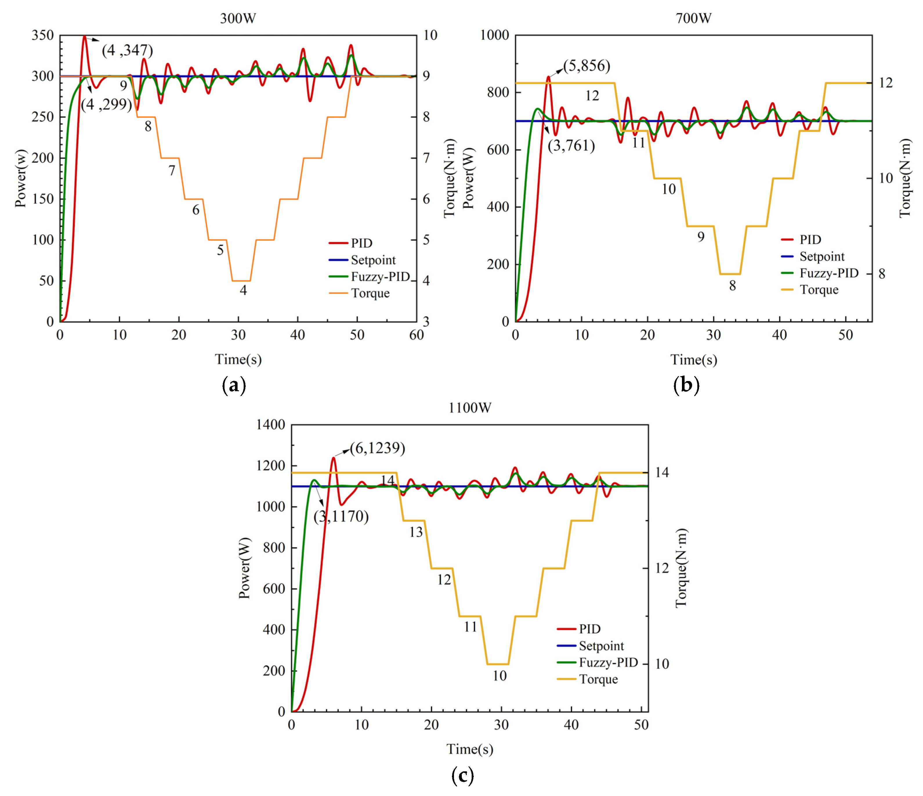
| Power | Controller | Overshoot | Rising Time | Adjustment Time | Downstroke |
|---|---|---|---|---|---|
| 300 W | Fuzzy PID | 0% | 4 s | 5 s | 5% |
| PID | 15.6% | 4 s | 8 s | 8.3% | |
| 500 W | Fuzzy PID | 2.2% | 3 s | 6 s | - |
| PID | 15% | 4 s | 10 s | - | |
| 700 W | Fuzzy PID | 8.7% | 3 s | 7 s | 3.6% |
| PID | 22.3% | 5 s | 11 s | 5% | |
| 900 W | Fuzzy PID | 7.8% | 3 s | 5 s | - |
| PID | 14.4% | 6 s | 11 s | - | |
| 1100 W | Fuzzy PID | 6.4% | 3 s | 8 s | 5.45% |
| PID | 12.6% | 6 s | 14 s | 9.09% | |
| 1300 W | Fuzzy PID | 5.5% | 3 s | 9 s | - |
| PID | 9.8% | 6 s | 15 s | - |
Disclaimer/Publisher’s Note: The statements, opinions and data contained in all publications are solely those of the individual author(s) and contributor(s) and not of MDPI and/or the editor(s). MDPI and/or the editor(s) disclaim responsibility for any injury to people or property resulting from any ideas, methods, instructions or products referred to in the content. |
© 2025 by the authors. Licensee MDPI, Basel, Switzerland. This article is an open access article distributed under the terms and conditions of the Creative Commons Attribution (CC BY) license (https://creativecommons.org/licenses/by/4.0/).
Share and Cite
Jiang, P.; Yang, Y.; Cao, C.; Dong, X. Implementation of Constant Power Control for a Reamer Using a Fuzzy PID Algorithm. Mathematics 2025, 13, 647. https://doi.org/10.3390/math13040647
Jiang P, Yang Y, Cao C, Dong X. Implementation of Constant Power Control for a Reamer Using a Fuzzy PID Algorithm. Mathematics. 2025; 13(4):647. https://doi.org/10.3390/math13040647
Chicago/Turabian StyleJiang, Pan, Yongkang Yang, Chenghui Cao, and Xinyu Dong. 2025. "Implementation of Constant Power Control for a Reamer Using a Fuzzy PID Algorithm" Mathematics 13, no. 4: 647. https://doi.org/10.3390/math13040647
APA StyleJiang, P., Yang, Y., Cao, C., & Dong, X. (2025). Implementation of Constant Power Control for a Reamer Using a Fuzzy PID Algorithm. Mathematics, 13(4), 647. https://doi.org/10.3390/math13040647