Article

Finite-Time and Fixed-Time Synchronization of Memristor-Based Cohen–Grossberg Neural Networks via a Unified Control Strategy

1
School of Mathematics and Statistics, Zhoukou Normal University, Zhoukou 466001, China
2
College of Mathematics and Statistics, Northwest Normal University, Lanzhou 730070, China
3
College of Mathematics and System Sciences, Xinjiang University, Urumqi 830046, China
*
Author to whom correspondence should be addressed.
Mathematics 2025, 13(4), 630; https://doi.org/10.3390/math13040630
Submission received: 25 December 2024 / Revised: 22 January 2025 / Accepted: 11 February 2025 / Published: 14 February 2025

Abstract

:
This article focuses on the problem of finite-time and fixed-time synchronization for Cohen–Grossberg neural networks (CGNNs) with time-varying delays and memristor connection weights. First, through a nonlinear transformation, an alternative system is derived from the Cohen–Grossberg memristor-based neural networks (MCGNNs) considered. Then, under the framework of the Filippov solution and by adjusting a key control parameter, some novel and effective criteria are obtained to ensure finite-time or fixed-time synchronization of the alternative networks via the unified control framework and under the same conditions. Furthermore, the two types of synchronization criteria are derived from the considered MCGNNs. Finally, some numerical simulations are presented to test the validity of these theoretical conclusions.

1. Introduction

In 1971, Cai [1] first proposed a memristor as the fourth basic element of a circuit via the basic circuit integral theory. However, researchers did not pay much attention to the memristor until HP Labs researchers realized a physical model of a memristor in 2008 [2]. With the passage of time, more and more research has been conducted on the memristor neural network, because a variable-weight artificial neural network constructed by a memristor can simulate the human brain better than other neural networks. That is why more and more people are committing themselves to memristor-based network research [3,4,5,6,7]. However, there has been little research on the dynamic characteristics of MCGNNs. Therefore, inspired by the application of memristor-based neural network control, studying the dynamics of MCGNNs is significant in both theory and practice.
Synchronous control [8], as a fundamental topic of neural networks [9,10], has attracted a lot of attention due to its practical applications in information communication and image processing. Most of the aforementioned existing articles mainly focus on asymptotic synchronization. In other words, only when time approaches infinity can synchronization be obtained. However, when used for control [11] and supervision, the network may be expected to achieve synchronization within a limited timeframe, especially in the engineering field. Moreover, finite-time control also has other advantages, such as better robustness and anti-interference properties.
Additionally, finite-time synchronization conclusions [12,13,14] generate the optimal convergence time, but the stability time of finite-time synchronization is a function related to the initial value of the system. Furthermore, not all initial values of all systems can be obtained in practice. In order to deal with this problem, Polyakov [15] and Andrieu [16] presented fixed-time stability, in which the consistency of the convergence time is given with respect to the initial conditions. Obviously, a fixed-time strategy [17] is superior to traditional finite-time techniques because it needs the controlled network to be stable within a fixed time and is independent of the initial value.
Based on the above analysis, this article proposes an MCGNN model with delays, and then studies whether the model can obtain finite-time and fixed-time synchronization under appropriate controllers. The main merits of this article can be summarized in the following paragraphs.
First, via the property behavior function, inverse function derivative theorem, and amplification function, we obtain CGNNs from the considered memristor transformation system.
Then, by studying the finite-time and fixed-time synchronization of alternative networks, we present the finite-time and fixed-time synchronization conditions for the model under consideration.
In addition, the criteria obtained in this article are easier to test and improve upon the conditions in [18,19,20,21,22]. Finally, the validity of the theoretical results is verified by numerical simulation.
The rest of this article is organized as follows: In Section 2, the model and preliminary knowledge of CGNNs with time-varying delay based on a memristor are presented. Section 3 studies the finite-time and fixed-time synchronization of the considered model under appropriate controllers. The validity of this proposed method is then demonstrated via numerical examples in Section 4. Finally, Section 5 draws some conclusions.
Notations: Let  R n  be the space of n-dimensional real column vectors. For  x = ( x 1 , , x n ) R n x  denotes a vector norm defined by  x = ( i = 1 n x i 2 ) 1 2 .  For matrix  P R n × n P  denotes its transpose, while  λ max ( P ) , λ min ( P ) , respectively, represent the maximum and minimum eigenvalue of matrix P and  P > 0  denotes that P is a positive definite matrix. Let  W ¯ i j = max { w ^ i j , w ˇ i j }  and  C ¯ i j = max { c ^ i j , c ˇ i j } .

2. Preliminaries

We investigate the following MCGNN model:
u ˙ i ( t ) = a i ( u i ( t ) ) [ b i ( u i ( t ) ) j = 1 n w i j ( u i ( t ) ) f j ( u j ( t ) ) j = 1 n c i j ( u i ( t ) ) f j ( u j ( t τ j ( t ) ) ) I i ] , i I = { 1 , 2 , . . . , n } ,
where  u i ( t )  denotes the state variable of the ith neuron at time t;  I i  is the external input to the ith neuron;  a i ( u i ( t ) )  and  b i ( u i ( t ) )  represent the amplification function and appropriately behaved function at time t, respectively;  f j ( u j ( t ) )  denotes the output of the jth neuron at time t; the time-varying delay  τ j ( t )  corresponds to the finite speed of the axonal signal transmission; and  w i j ( u i ( t ) )  and  c i j ( u i ( t ) )  are memristive connection weights satisfying the following conditions:
w i j ( u i ( t ) ) = M i j C i × s i g n i j ,   c i j ( u i ( t ) ) = M ˜ i j C i × s i g n i j ,   s i g n i j = 1 , i j , 1 , i = j ,
where  M i j  and  M ˜ i j  represent the memductances of memristors  R i j  and  R ˜ i j , respectively. In addition,  R i j  denotes the memristor between  f i ( u i ( t ) )  and  u i ( t ) , while  R ˜ i j  represents the memristor between  f i ( u i ( t τ i ( t ) ) )  and  u i ( t ) .
On the basis of the characteristics of the current–voltage and memristor features,
w i j ( u i ( t ) ) = w ^ i j , u i ( t ) < T i , w ˇ i j , u i ( t ) T i ,
c i j ( u i ( t ) ) = c ^ i j , u i ( t ) < T i , c ˇ i j , u i ( t ) T i ,
in which  T i > 0 w ^ i j , w ˇ i j , c ^ i j , c ˇ i j , i , j I  are constants.
In the following list, we present some necessary assumptions:
(H1). 
We assume that  0 τ j ( t ) τ , where  τ = max j I { sup t 0 τ j ( t ) } .
(H2). 
a i ( u )  is continuous and monotone and we assume  0 < a ̲ i a i ( u ) a ¯ i , u R , i I .
(H3). 
There exists a constant  l i  such that  b i ( u ) l i , where  b 1 ( u )  represents the derivative of  b i ( u ) ,   u R  and  b i ( 0 ) = 0 ,   i I .
(H4). 
There exists a constant  L i > 0  such that  f i ( x ) f i ( y ) L i x y x , y R ,   x y ,   i I .
(H5). 
There exists a constant  M i > 0  such that  f i ( x ) M i  for bounded x and  x R ,   i I .
Suppose  h i ( u i )  is an antiderivative of  1 a i ( u i )  that satisfies  h i ( 0 ) = 0 d d u i h i ( u i ) = 1 a i ( u i )  and  d d u i h i 1 ( u i ) = a i ( u i ) .  According to  ( H 3 ) b i ( t , h i 1 ( z ) )  is differentiable. We denote  x i ( t ) = h i ( u i ( t ) ) , and then  x ˙ i ( t ) = u ˙ i ( t ) a i ( u i ( t ) )  and  u i ( t ) = h i 1 ( x i ( t ) ) . From system (1), we obtain
x i ˙ ( t ) = b i ( h i 1 ( x i ( t ) ) ) + j = 1 n w i j ( h i 1 ( x i ( t ) ) ) f j ( h j 1 ( x j ( t ) ) ) + j = 1 n c i j ( h i 1 ( x i ( t ) ) ) f j ( h j 1 ( x j ( t τ j ( t ) ) ) ) + I i .
The response system of (1) is described by
v i ˙ ( t ) = a i ( v i ( t ) ) [ b i ( v i ( t ) ) j = 1 n w i j ( v i ( t ) ) f j ( v j ( t ) ) j = 1 n c i j ( v i ( t ) ) f j ( v j ( t τ j ( t ) ) ) I i ] + R i ( t ) ,
in which  R i ( t )  is a suitable feedback controller, which is defined as follows:
R i ( t ) = p i ( v i ( t ) u i ( t ) ) η i s i g n ( v i ( t ) u i ( t ) ) j = 1 n k i j s i g n ( v j ( t ) u j ( t ) ) × | v j ( t ) u j ( t ) | ω j = 1 n δ i j s i g n ( v i ( t ) u i ( t ) ) | v j ( t τ j ( t ) ) u j ( t τ j ( t ) ) | ,
where  p i , η i > 0 δ i j > 0 , and matrix  K = ( k i j ) n × n > 0 .
u i ( s ) = φ i ( s ) , v i ( s ) = ϕ i ( s ) ,  and  i = 1 , , n  are the initial conditions of system (1) and system (3), in which  s [ τ , 0 ] , i I , φ i ( s ) ,  and  ϕ i ( s )  are continuous.
Similar to the analysis of (2), we obtain
y i ˙ ( t ) = b i ( h i 1 ( y i ( t ) ) ) + j = 1 n w i j ( h i 1 ( y i ( t ) ) ) f j ( h j 1 ( y j ( t ) ) ) + j = 1 n c i j ( h i 1 ( y i ( t ) ) ) × f j ( h j 1 ( y j ( t τ j ( t ) ) ) ) + I i p i a i ( h i 1 ( y i ( t ) ) ) ( h i 1 ( y i ( t ) ) h i 1 ( x i ( t ) ) ) η i a i ( h i 1 ( y i ( t ) ) ) s i g n ( h i 1 ( y i ( t ) ) h i 1 ( x i ( t ) ) ) 1 a i ( h i 1 ( y i ( t ) ) ) j = 1 n k i j × s i g n ( h j 1 ( y j ( t ) ) h j 1 ( x j ( t ) ) ) | h j 1 ( y j ( t ) ) h j 1 ( x j ( t ) ) | ω 1 a i ( h i 1 ( y i ( t ) ) ) j = 1 n δ i j s i g n ( h i 1 ( y i ( t ) ) h i 1 ( x i ( t ) ) ) | h j 1 ( y j ( t τ j ( t ) ) ) h j 1 ( x j ( t τ j ( t ) ) ) | .
where  y i ( t ) = h i ( v i ( t ) ) .
Now, we define  e ( t ) = ( e 1 ( t ) , e 2 ( t ) , , e n ( t ) ) T = y ( t ) x ( t ) .
Therefore, from (2) and (5), we find that
e ˙ i ( t ) = b i ( h i 1 ( y i ( t ) ) ) b i ( h i 1 ( x i ( t ) ) ) + j = 1 n { w i j ( h i 1 ( y i ( t ) ) ) f j ( h j 1 ( y j ( t ) ) ) w i j ( h i 1 ( x i ( t ) ) ) f j ( h j 1 ( x j ( t ) ) ) } + j = 1 n { c i j ( h i 1 ( y i ( t ) ) ) f j ( h j 1 ( y j ( t τ j ( t ) ) ) ) c i j ( h i 1 ( x i ( t ) ) ) f j ( h j 1 ( x j ( t τ j ( t ) ) ) ) } p i a i ( h i 1 ( y i ( t ) ) ) ( h i 1 ( y i ( t ) ) h i 1 ( x i ( t ) ) ) η i a i ( h i 1 ( y i ( t ) ) ) s i g n ( h i 1 ( y i ( t ) ) h i 1 ( x i ( t ) ) ) 1 a i ( h i 1 ( y i ( t ) ) ) j = 1 n k i j × s i g n ( h j 1 ( y j ( t ) ) h j 1 ( x j ( t ) ) ) | h j 1 ( y j ( t ) ) h j 1 ( x j ( t ) ) | ω 1 a i ( h i 1 ( y i ( t ) ) ) j = 1 n δ i j s i g n ( h i 1 ( y i ( t ) ) h i 1 ( x i ( t ) ) ) × | h j 1 ( y j ( t τ j ( t ) ) ) h j 1 ( x j ( t τ j ( t ) ) ) | .
Definition 1 
([23]). The origin of system (6) is said to be globally finite-time stable if, for any solution  e ( t , e 0 )  of (6), the following statements hold:
(i) Lyapunov stability: For any  ε > 0 , there is a  δ = δ ( ε ) > 0  such that  e ( t , e 0 ) < ε  for any  e 0 < ε δ  and  t 0 .
(ii) Finite-time convergence: There exists a function  T : R n { 0 } ( 0 , + ) , called the settling time function, such that  lim t T ( e 0 ) = 0  and  e ( t , e 0 ) = 0  for all  t T ( e 0 ) .
Definition 2 
([23]). The origin of system (6) is said to be fixed-time stable if it is globally finite-time stable and the settling time function  T ( e 0 )  is bounded for any  e 0 R n , i.e., there exists  T max > 0  such that  T ( e 0 ) T max  for all  e 0 R n .
Lemma 1 
([12]). For system (6), if there exists a regular, positive definite and radially unbounded function  V ( x ( t ) ) : R n R + , satisfying the following inequality
V ˙ ( x ( t ) ) r α V η ( x ( t ) ) , x ( t ) R n { 0 } .
where  r > 0 , α > 0 , η 0 , then the following statements hold:
(i) When  η = 0 , system (6) is finite-time stable and the convergence time is as follows:
T 1 T 1 * = V ( x 0 ) r + α .
(ii) When  0 < η < 1 , system (6) is finite-time stable and the convergence time is as follows:
T 2 T 2 * = 1 1 η r 1 η α 1 η 1 + α r 1 η V ( x 0 ) 1 η 1 .
(iii) When  η = 1 , system (6) is finite-time stable and the convergence time is as follows:
T 3 T 3 * = 1 α ln r + α V ( x 0 ) r .
(iv) When  η > 1 , system (6) is fixed-time stable and the convergence time is as follows:
T 4 T 4 * = 1 r ( r α ) 1 η ( 1 + 1 η 1 ) .
Lemma 2 
([24]). If  h 1 , h 2 , . . . , h n , θ ,  and  k  are all positive constants and  0 < θ 1 , k > 1 , then
i = 1 n h i θ ( i = 1 n h i ) θ , i = 1 n h i k n 1 k ( i = 1 n h i ) k .

3. Finite-Time Synchronization

Theorem 1. 
Assume that assumptions  ( H 1 ) ( H 5 )  hold and matrix  K > 0 . If  p i > 0 ,   η i > 0 ,   δ i j > 0 ,   β i > 0 , and
δ i j a ̲ j C ¯ i j L j a ¯ j a ¯ i ,
a ̲ i l i + p i a ̲ i a ¯ i j = 1 n L i a ¯ i W ¯ j i 0 ,
β i = η i a ¯ i j = 1 n | w ^ i j w ˇ i j | + | c ^ i j c ˇ i j | M j , β = min i I { β i } ,
where  i , j I ,  then the following statements hold:
(i) When  ω = 0 , system (6) is finite-time stable and the convergence time is as follows:
T 5 T 5 * = V ( t 0 ) n β + ε .
(ii) When  0 < ω < 1 , system (6) is finite-time stable and the convergence time is as follows:
T 6 T 6 * = 1 1 ω ( n β ) 1 ω ε 1 ω 1 + ε n β 1 ω V ( t 0 ) 1 ω 1 .
(iii) When  ω = 1 , system (6) is finite-time stable and the convergence time is as follows:
T 7 T 7 * = 1 ε ln n β + ε V ( t 0 ) n β .
(iv) When  ω > 1 , system (6) is fixed-time stable and the convergence time is as follows:
T 8 T 8 * = 1 n β n β Δ 1 ω 1 + 1 ω 1 ,
where  Δ = ε n 1 ω .
Proof. 
Since  b i ( u )  and  h i 1 ( λ )  are differentiable and strictly monotonically increasing,  b i ( 0 ) = 0  and  h i 1 ( 0 ) = 0  and  b i ( h i 1 ( λ ) )  are differentiable and strictly monotonically increasing for  λ R . Hence,
s i g n ( e i ( t ) ) b i ( h i 1 ( y i ( t ) ) ) b i ( h i 1 ( x i ( t ) ) ) = s i g n ( e i ( t ) ) b i ( ξ 1 ) ( h i 1 ( y i ( t ) ) h i 1 ( x i ( t ) ) ) = s i g n ( e i ( t ) ) b i ( ξ 1 ) ( h i 1 ( ξ 2 ) ) ( y i ( t ) x i ( t ) ) l i a ̲ i e i ( t ) ,
where  ξ 1  is between  h i 1 ( y i ( t ) )  and  h i 1 ( x i ( t ) )  and  ξ 2  is between  x i ( t )  and  y i ( t ) .
Therefore, similarly to (7), it can be found that
s i g n ( e i ( t ) ) p i a i ( h i 1 ( y i ( t ) ) ) ( h i 1 ( y i ( t ) ) h i 1 ( x i ( t ) ) ) p i a ̲ i a ¯ i e i ( t ) ,
s i g n ( e i ( t ) ) η i a i ( h i 1 ( y i ( t ) ) ) s i g n ( h i 1 ( y i ( t ) ) h i 1 ( x i ( t ) ) ) η i a ¯ i ,
and
s i g n ( e i ( t ) ) 1 a i ( h i 1 ( y i ( t ) ) ) j = 1 n δ i j s i g n ( h i 1 ( y i ( t ) ) h i 1 ( x i ( t ) ) ) | h j 1 ( y j ( t τ j ( t ) ) ) h j 1 ( x j ( t τ j ( t ) ) ) | 1 a ¯ i j = 1 n δ i j a ̲ j | e j ( t τ j ( t ) ) | .
From  ( H 2 ) , ( H 4 ) , and  ( H 5 ) , it can be found that
| w i j ( h i 1 ( y i ( t ) ) ) f j ( h j 1 ( y j ( t ) ) ) w i j ( h i 1 ( x i ( t ) ) ) f j ( h j 1 ( x j ( t ) ) ) | | w i j ( h i 1 ( y i ( t ) ) ) f j ( h j 1 ( y j ( t ) ) ) w i j ( h i 1 ( y i ( t ) ) ) f j ( h j 1 ( x j ( t ) ) ) | + | w i j ( h i 1 ( y i ( t ) ) ) f j ( h j 1 ( x j ( t ) ) ) w i j ( h i 1 ( x i ( t ) ) ) f j ( h j 1 ( x j ( t ) ) ) | W ¯ i j L j a ¯ j | e j ( t ) | + | w ^ i j w ˇ i j | M j .
In a similar way, one obtains
| c i j ( h i 1 ( y i ( t ) ) f j ( h j 1 ( y j ( t τ j ( t ) ) ) ) c i j ( h i 1 ( x i ( t ) ) ) f j ( h j 1 ( x j ( t τ j ( t ) ) ) ) | C ¯ i j L j a ¯ j | e j ( t τ j ( t ) ) | + | c ^ i j c ˇ i j | M j .
We define the Lyapunov functional
V ( t ) = i = 1 n | e i ( t ) | , i I ,
then
D + V ( t ) = i = 1 n s i g n ( e i ( t ) ) D + e i ( t ) i = 1 n { ( a ̲ i l i + p i a ̲ i a ¯ i ) | e i ( t ) | + j = 1 n L j a ¯ j ( W ¯ i j | e j ( t ) | + C ¯ i j | e j ( t τ j ( t ) ) | ) + j = 1 n ( | w ^ i j w ˇ i j | + | c ^ i j c ˇ i j | ) M j η i a ¯ i 1 a ¯ i j = 1 n s i g n ( e i ( t ) ) k i j × s i g n ( h j 1 ( y j ( t ) ) h j 1 ( x j ( t ) ) ) | h j 1 ( y j ( t ) ) h j 1 ( x j ( t ) ) | ω 1 a ¯ i j = 1 n δ i j a ̲ j | e j ( t τ j ( t ) ) | } i = 1 n { ( a ̲ i l i + p i a ̲ i a ¯ i ) | e i ( t ) | + j = 1 n L j a ¯ j W ¯ i j | e j ( t ) | 1 a ¯ i j = 1 n s i g n ( e i ( t ) ) k i j s i g n ( h j 1 ( y j ( t ) ) h j 1 ( x j ( t ) ) ) | h j 1 ( y j ( t ) ) h j 1 ( x j ( t ) ) | ω β } i = 1 n ( a ̲ i l i + p i a ̲ i a ¯ i j = 1 n L i a ¯ i W ¯ j i ) | e i ( t ) | β λ min ( K ) min i I | a ̲ i | ω max i I { a ¯ i } | e i ( t ) | ω λ min ( K ) min i I | a ̲ i | ω max i I { a ¯ i } i = 1 n | e i ( t ) | ω n β = ε i = 1 n | e i ( t ) | ω n β ,
where  ε = λ min ( K ) min i I | a ̲ i | ω max i I { a ¯ i } .
(i) When  ω = 0 , from Lemma 1, we know that system (6) is finite-time stable and the convergence time is as follows:
T 5 T 5 * = V ( t 0 ) n β + ε .
(ii) When  0 < ω 1 , it can be obtained that
i = 1 n | e i ( t ) | ω i = 1 n | e i ( t ) | ω .
So,
D + V ( t ) ε V ω ( t ) n β ,
From Lemma 1, we know that system (6) is finite-time stable with  0 < ω < 1  and when the convergence time is as follows:
T 6 T 6 * = 1 1 ω ( n β ) 1 ω ε 1 ω 1 + ε n β 1 ω V ( t 0 ) 1 ω 1 .
System (6) is especially finite-time stable with  ω = 1  and the convergence time
T 7 T 7 * = 1 ε ln n β + ε V ( t 0 ) n β .
(iii) When  ω > 1 , by virtue of Lemma 2, it can be found that
i = 1 n | e i | ω n 1 ω i = 1 n | e i | ω ,
then
D + V ( t ) ε n 1 ω V ω ( t ) n β = Δ V ω ( t ) n β ,
where  Δ = ε n 1 ω . Then, from Lemma 1, system (6) is fixed-time stable and the convergence time is as follows:
T 8 T 8 * = 1 n β n β Δ 1 ω 1 + 1 ω 1 .
Theorem 2. 
Assume that assumptions  ( H 1 ) ( H 5 )  hold and matrix  K > 0 . If  p i > 0 , η i > 0 ,   δ i j > 0 , and
δ i j a ̲ j C ¯ i j L j a ¯ j a ¯ i ,
a ̲ i l i + p i a ̲ i a ¯ i j = 1 n L i a ¯ i W ¯ j i 0 ,
β i = 0 ,
for any  i I ,  then the following statements hold:
(i) When  0 ω < 1 , system (6) is finite-time stable and the convergence time is as follows:
T 9 T 9 * = V 1 ω ( t 0 ) ε ( 1 ω ) .
(ii) When  ω = 1 , system (6) is exponentially stable.
(iii) When  ω > 1 , system (6) is asymptotically stable.
Proof. 
It can be derived that
D + V ( t ) ε i = 1 n | e i ( t ) | ω ,
when  ω = 0  and  D + V ( t ) ε . System (6) is finite-time stable and the convergence time is  T 9 V ( t 0 ) ε .
When  0 < ω < 1 ,
D + V ( t ) ε V ω ( t ) .
Hence, system (6) is finite-time stable and the convergence time is  T 9 V 1 ω ( t 0 ) ε ( 1 ω ) .
When  ω = 1 , its exponential stability is evident.
When  ω > 1 , from Lemma 2, we find that
D + V ( t ) Δ V ω ( t ) ,
which implies that
V ( t ) V 1 ω ( t 0 ) + Δ ( w 1 ) t 1 1 ω ,
which reveals that  lim t + V ( t ) = 0 , so system (6) is asymptotically stable. □
If the amplification function  a i ( u i ( t ) ) = 1  for  t > 0 , then system (1) and system (3) take the following forms, respectively:
u ˙ i ( t ) = b i ( u i ( t ) ) + j = 1 n w i j ( u i ( t ) ) f j ( u j ( t ) ) + j = 1 n c i j ( u i ( t ) ) f j ( u j ( t τ j ( t ) ) ) + I i , i I .
v ˙ i ( t ) = b i ( v i ( t ) ) + j = 1 n w i j ( v i ( t ) ) f j ( v j ( t ) ) + j = 1 n c i j ( v i ( t ) ) f j ( v j ( t τ j ( t ) ) ) + I i + R i ( t ) , i I ,
in which  R i ( t )  is the controller mentioned above.
From Theorems 1 and 2, the corollaries can be obtained as follows.
Corollary 1. 
Assume that assumptions  ( H 1 ) ( H 5 )  hold and matrix  K > 0 . If  p i > 0 , η i > 0 ,   δ i j > 0 , β i > 0 , and
δ i j C ¯ i j L j ,
l i + p i j = 1 n L i W ¯ j i 0 ,
β i = η i j = 1 n | w ^ i j w ˇ i j | + | c ^ i j c ˇ i j | M j , β = min i I { β i } ,
for any  i I ,  then the following statements hold:
(i) When  ω = 0 , system (6) is finite-time stable and the convergence time is as follows:
T 1 T 1 * = V ( t 0 ) n β + ε .
(ii) When  0 < ω < 1 , system (6) is finite-time stable and the convergence time is as follows:
T 2 T 2 * = 1 1 ω ( n β ) 1 ω ε 1 ω 1 + ε n β 1 ω V ( t 0 ) 1 ω 1 .
(iii) When  ω = 1 , system (6) is finite-time stable and the convergence time is as follows:
T 3 T 3 * = 1 ε ln n β + ε V ( t 0 ) n β .
(iv) When  ω > 1 , system (6) is fixed-time stable and the convergence time is as follows:
T 4 T 4 * = 1 n β ( n β Δ ) 1 ω ( 1 + 1 ω 1 ) .
Corollary 2. 
Assume that assumptions  ( H 1 ) ( H 5 )  hold and matrix  K > 0 . If  p i > 0 , η i > 0 ,   δ i j > 0 , and
δ i j C ¯ i j L j ,
l i + p i j = 1 n L i a ¯ i W ¯ j i 0 ,
β i = 0 ,
for any  i I ,  then the following statements hold:
(i) When  0 ω < 1 , system (6) is finite-time stable and the convergence time is as follows:
T 9 T 9 * = V 1 ω ( t 0 ) ε ( 1 ω ) .
(ii) When  ω = 1 , system (6) is exponentially stable.
(iii) When  ω > 1 , system (6) is asymptotically stable.
Remark 1. 
It is noted that the dynamics (1) and (3) of the CGNN are discontinuous, which is different from traditional neural networks with continuous dynamics. Furthermore, traditional solutions for systems (1) and (3) may not exist. However, based on set-valued mappings and differential inclusions, Filippov solutions for systems (1) and (3) with initial values exist and can also be extended to the intervals  [ 0 , + ) . That is to say, the dynamic actions of networks (1) and (3) can be discussed by means of the Filippov solution.
Remark 2. 
How to handle the  a i ( · )  of Cohen–Grossberg neural networks is important in investigating synchronization. Unlike previous works, new MCGNNs are derived in this paper by a nonlinear transformation. In this way, the Lyapunov functions used in constructing the theorem are very simple and special assumptions are not needed, such as the following:
τ ˙ j ( t ) ϱ < 1 ,
| a i ( u i ) a i ( v i ) | N i | u i v i | ,
a i ( u i ) b i ( u i ) a i ( v i ) b i ( v i ) u i v i γ i ,
in which  ϱ , N i ,  and  γ i  are constants mentioned in the articles [25,26]. With this in mind, the following remarks can be made.
Remark 3. 
In [27,28], two types of the synchronization of neural networks were investigated. However, the constructed Lyapunov functions were very complex in the citations mentioned above. Unlike them, the Lyapunov functions in our Theorem 1 are very simple. Additionally, the controller in this paper is different from the one in [27]. In [28], the controller contains two items ( 0 < α < 1 , β > 1 ) to realize fixed-time synchronization in the analysis of its theorems. In this article, we only need a single exponential term for the controller and only need to adjust the values of the control parameters  δ ( 0 < δ < 1 , δ = 0 , δ = 1 , δ > 1 )  to obtain finite-time and fixed-time synchronization.
Remark 4. 
In fact, based on different control tactics, the finite-time and fixed-time synchronization of a CGNN are proposed in citations [7,16], respectively. However, most results for these two forms of the synchronization of a CGNN cannot be obtained simultaneously. This article provides a unified control strategy to obtain the finite-time or fixed-time synchronization of a CGNN with discontinuous right end terms.
Remark 5. 
In Theorems 1 and 2, we investigated finite-time and fixed-time synchronization problems for MCGNNs with time-varying delays. Usually, in practical engineering processes, it is more important to achieve synchronization goals in a finite or fixed amount of time, rather than just achieving asymptotic implementation. Therefore, the results of this article improve upon previous conclusions [25,26,29].

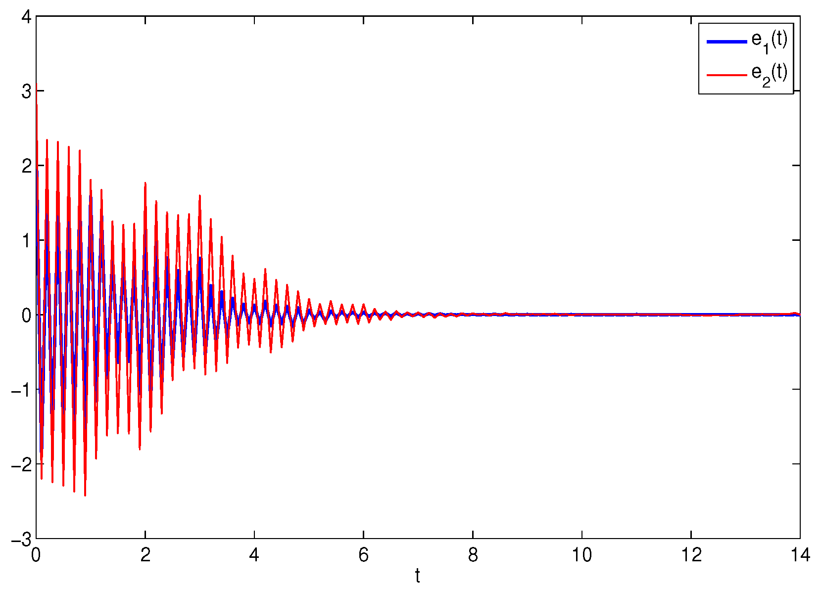
4. Numerical Simulations

A numerical simulation is provided to demonstrate the effectiveness of the conclusions achieved in the previous section.
Example 1. 
Consider the following MCGNN model:
u ˙ i ( t ) = a i ( u i ( t ) ) [ b i ( u i ( t ) ) j = 1 2 w i j ( u i ( t ) ) f j ( u j ( t ) ) j = 1 2 c i j ( u i ( t ) ) f j ( u j ( t τ j ( t ) ) ) I i ] , i = 1 , 2 ,
where
w 11 ( u 1 ) = 2 , u 1 ( t ) < 0.4 , 1.5 , u 1 ( t ) 0.4 , w 12 ( u 1 ) = 0.1 , u 1 ( t ) < 0.4 , 0.3 , u 1 ( t ) 0.4 ,
w 21 ( u 2 ) = 2.5 , u 2 ( t ) < 0.4 , 2 , u 2 ( t ) 0.4 , w 22 ( u 2 ) = 0.4 , u 2 ( t ) < 0.4 , 0.6 , u 2 ( t ) 0.4 ,
c 11 ( u 1 ) = 1.5 , u 1 ( t ) < 0.4 , 1.2 , u 1 ( t ) 0.4 , c 12 ( u 1 ) = 0.6 , u 1 ( t ) < 0.4 , 0.4 , u 1 ( t ) 0.4 ,
c 21 ( u 2 ) = 0.5 , u 2 ( t ) < 0.4 , 0.8 , u 2 ( t ) 0.4 , c 22 ( u 2 ) = 2.5 , u 2 ( t ) < 0.4 , 2.3 , u 2 ( t ) 0.4 .
We consider response system (18) as being defined as in (3), with  i = 1 , 2 a i ( u i ) = 1 + 0.3 1 + u i 2 ; i = 1 , 2 ; b 1 ( u 1 ) = 1.8 u 1 ; b 2 ( u 2 ) = 1.6 u 2 ; τ 1 ( t ) = τ 2 ( t ) = e t 1 + e t ;  and  f i ( u i ) = tanh ( u i ( t ) ) , i = 1 , 2 , I 1 = 0 , I 2 = 0 . Obviously,  0 τ 1 ( t ) , τ 2 ( t ) 1 , 1.1 a i ( u i ) 1.3 , b 1 ( u 1 ) = 1.8 , b 2 ( u 2 ) = 1.6 ,   b i ( 0 ) = 0 ,   | f i ( u i ) f i ( v i ) | | u i v i | ,   | f i ( u i ) | 1 ,  and  i , j = 1 , 2 . Therefore,  ( H 1 ) ( H 5 )  hold for system (18). The chaotic attractor of model (18) with the initial conditions  u 1 ( s ) = 0.6 ,   u 2 ( s ) = 0.4 ,   s [ 1 , 0 )  is shown in Figure 1. In addition, the initial conditions of system (3) are provided, as  v 1 ( s ) = 3  and  v 2 ( s ) = 3.5 , s [ 1 , 0 ) .
By simple computing, we obtain  w ¯ 11 = 2 ; w ¯ 12 = 0.3 ; w ¯ 21 = 2.5 ; w ¯ 22 = 0.6 ; c ¯ 11 = 1.5 c ¯ 12 = 0.6 ; c ¯ 21 = 0.8 ; c ¯ 22 = 2.5 ; a ¯ 1 = a ¯ 2 = 1.3 ;   a ̲ 1 = a ̲ 2 = 1 ;   l 1 = 1.8 ;   l 2 = 1.6 ; τ = 1 ;   L 1 = L 2 = 1 ;   M 1 = M 2 = 1 ;   η 1 1.56 ; η 2 1.56 δ 11 2.3045 ;   δ 12 0.9218 ; δ 21 1.2291 ;   δ 22 3.8409 ;  and  p i 2.3220 .  Now, let  p 1 = 8 ; p 2 = 7 ; η 1 = 1.6 ; η 2 = 1.6 ; k 11 = 1 ; k 12 = k 21 = 0 ; k 22 = 0.8 ; δ 11 = 2.4 ; δ 12 = 0.93 ;  and  δ 21 = 2.5 ; δ 22 = 4 .  Furthermore, we obtain  β 1 = β 2 = β = 0.03  and  ε = 0.64 . Then, Theorem 1 satisfies the first and second conditions. The trajectories of the error systems are given in Figure 2, Figure 3, Figure 4 and Figure 5 with four different parameters: (1)  ω = 0 ; (2)  ω = 0.2 ; (3)  ω = 1 ; and (4)  ω = 1.5 . By computation,  T 5 * = 8.46 ; T 6 * = 7.72 ; T 7 * = 6.25 ;  and  T 8 * = 16.18 .

5. Conclusions

This paper is devoted to the finite-time and fixed-time synchronization of CGNNs via a differential conclusion and a discontinuous protocol. How to handle  a i ( · )  is very important when researching the dynamic behavior of CGNNs. Different from previous works, in this paper, new systems of MCGNNs are derived using a nonlinear transformation. In this way, the Lyapunov functions used in constructing the theorem are very simple and special assumptions are not needed. Then, by using Filippov non-smooth theory and a discontinuous controller, the finite-time or fixed-time synchronization of MCGNNs can be obtained by the unified control framework and by adjusting the control parameter. Finally, the obtained theoretical conclusions were tested using examples.
Recently, because intermittent control is more economical and can reduce the amount of information transmitted, this control method has naturally attracted increasing interest within a variety of applications. For adaptive control, these control parameters can automatically adjust themselves according to some properly established updating laws. Hence, it is meaningful to focus on the fixed-time synchronization of delayed dynamic networks under adaptive intermittent control as a research topic.

Author Contributions

M.L. established the mathematical model, performed theoretical analysis, and wrote the original draft; H.J. provided modeling ideas and analysis methods; C.H. checked the correctness of the theoretical results; J.W. and B.L. performed the simulation experiments. All authors read and approved the final manuscript.

Funding

This work was supported by the Key Research Projects in the University of Henan Province (Grant No. 24A110015), by the Natural Science Foundation of Henan Province (General Program, Grant No. 242300421418), and by the National Natural Science Foundation of the People’s Republic of China (Grant No. 62366049).

Data Availability Statement

No new data were collected or produced in this study.

Acknowledgments

The authors are grateful to the editors and anonymous reviewers for their valuable suggestions and comments, which greatly improved the presentation of this paper.

Conflicts of Interest

The authors declare that they have no competing interests.

References

  1. Chua, L. Memristor-the missing circuit element. IEEE Trans. Circuits Syst. 1971, 18, 507–519. [Google Scholar] [CrossRef]
  2. Strukov, D.; Snider, G.; Stewart, D.; Williams, R. The missing memristor found. Nature 2008, 453, 80–83. [Google Scholar] [CrossRef]
  3. Xu, W.; Zhu, S.; Fang, X.; Wang, W. Adaptive anti-synchronization of memristor-based complex-valued neural networks with time delays. Phys. Stat. Mech. Its Appl. 2019, 535, 122427. [Google Scholar] [CrossRef]
  4. Li, H.; Fang, J.; Li, X.; Huang, T. Exponential synchronization of multiple impulsive discrete-time memristor-based neural networks with stochastic perturbations and time-varying delays. Neurocomputing 2020, 392, 86–97. [Google Scholar] [CrossRef]
  5. He, J.; Pei, L. Function matrix projection synchronization for the multi-time delayed fractional order memristor-based neural networks with parameter uncertainty. Appl. Math. Comput. 2023, 454, 128110. [Google Scholar] [CrossRef]
  6. Wang, F.; Chen, Y. Mean square exponential stability for stochastic memristor-based neural networks with leakage delay. Chaos Soliton. Fract. 2021, 146, 110811. [Google Scholar] [CrossRef]
  7. Ren, F.; Jiang, M.; Xu, H.; Fang, X. New finite-time synchronization of memristive Cohen-Grossberg neural network with reaction-diffusion term based on time-varying delay. Neural Comput. Appl. 2021, 33, 4315–4328. [Google Scholar] [CrossRef]
  8. Wu, X.; Liu, S.; Wang, H. Pinning synchronization of fractional memristor-based neural networks with neutral delays and reaction-diffusion terms. Commun. Nonlinear Sci. Numer. Simul. 2023, 118, 107039. [Google Scholar] [CrossRef]
  9. Sarra, Z.; Bouziane, M.; Bouddou, R.; Benbouhenni, H.; Mekhilef, S.; Elbarbary, Z.M.S. Intelligent control of hybrid energy storage system using NARX-RBF neural network techniques for microgrid energy management. Energy Rep. 2024, 12, 5445–5461. [Google Scholar] [CrossRef]
  10. Zaidi, S.; Meliani, B.; Bouddou, R.; Belhadj, S.M.; Bouchikhi, N. Comparative study of different types of DC/DC converters for PV systems using RBF neural network-based MPPT algorithm. J. Renew. Energy 2024, 1, 13–31. [Google Scholar] [CrossRef]
  11. Adiche, S.; Larbi, M.; Toumi, D.; Bouddou, R.; Bajaj, M.; Bouchikhi, N.; Belabbes, A.; Zaitsev, I. Advanced control strategy for AC microgrids: A hybrid ANN-based adaptive PI controller with droop control and virtual impedance technique. Sci. Rep. 2024, 14, 31057. [Google Scholar] [CrossRef] [PubMed]
  12. Ji, G.; Hu, C.; Yu, J.; Jiang, H. Finite-time and fixed-time synchronization of discontinuous complex networks: A unified control framework design. J. Franklin Inst. 2018, 355, 4665–4685. [Google Scholar] [CrossRef]
  13. Li, Y.; Zhang, J.; Lu, J.; Lou, J. Finite-time synchronization of complex networks with partial communication channels failure. Inf. Sci. 2023, 634, 539–549. [Google Scholar] [CrossRef]
  14. Jin, X.; Jiang, J.; Chi, J.; Wu, X. Adaptive finite-time pinned and regulation synchronization of disturbed complex networks. Commun. Nonlinear Sci. Numer. Simul. 2023, 124, 107319. [Google Scholar] [CrossRef]
  15. Wang, L.; Tan, X.; Wang, Q.; Hu, J. Multiple finite-time synchronization and settling-time estimation of delayed competitive neural networks. Neurocomputing 2023, 124, 107319. [Google Scholar] [CrossRef]
  16. Polyakov, A. Nonlinear feedback design for fixed-time stabilization of linear control systems. IEEE Trans. Autom. Control 2012, 57, 2106–2110. [Google Scholar] [CrossRef]
  17. Aouiti, C.; Assali, E.; Foutayeni, Y. Finite-time and fixed-time synchronization of inertial Cohen-Grossberg-Type neural networks with time varying delays. Neural Process. Lett. 2019, 50, 2407–2436. [Google Scholar] [CrossRef]
  18. Pu, H.; Li, F. Finite-/fixed-time synchronization for Cohen-Grossberg neural networks with discontinuous or continuous activations via periodically switching control. Cogn. Neurodyn. 2022, 16, 195–213. [Google Scholar] [CrossRef]
  19. Wei, R.; Cao, J.; Alsaedi, A. Fixedtime sSynchronization of Memristive Cohen-Grossberg neural networks with impulsive effects. Int. J. Control, Autom. Syst. 2018, 16, 2214–2224. [Google Scholar] [CrossRef]
  20. Kong, F.; Zhu, Q.; Liang, F. Robust fixed-time synchronization of discontinuous Cohen-Grossberg neural networks with mixed time delays. Nonlinear Anal. Model. 2019, 24, 603–625. [Google Scholar] [CrossRef]
  21. Hui, M.; Wei, C.; Zhang, J.; Iu, H.H.; Luo, N.; Yao, R. Finite-time synchronization of Memristor-based fractional order Cohen-Grossberg neural networks. IEEE Access 2020, 8, 2214–2224. [Google Scholar] [CrossRef]
  22. Pershin, Y.; Ventra, M. On the validity of memristor modeling in the neural network literature. Neural Netw. 2020, 121, 52–56. [Google Scholar] [CrossRef]
  23. Jiang, M.; Wang, S.; Mei, J.; Shen, Y. Finite-time synchronization control of a class of memristor-based recurrent neural networks. Neural Netw. 2015, 63, 133–140. [Google Scholar] [CrossRef] [PubMed]
  24. Mei, J.; Jiang, M.; Wang, B.; Long, B. Finite-time parameter identification and adaptive synchronization between two chaotic neural networks. J. Frankl. Inst. 2013, 350, 1617–1633. [Google Scholar] [CrossRef]
  25. Zhu, Q.; Cao, J. Adaptive synchronization of chaotic Cohen-Grossberg neural networks with mixed time delays. Nonlinear Dyn. 2010, 61, 517. [Google Scholar] [CrossRef]
  26. Gan, Q. Adaptive synchronization of Cohen-Grossberg neural networks with unknown parameters and mixed time-varying delays. Commun. Nonlinear Sci. Numer. Simul. 2012, 17, 3040–3049. [Google Scholar] [CrossRef]
  27. Wei, R.; Cao, J.; Alsaedi, A. Finite-time and fixed-time synchronization analysis of inertial memristive neural networks with time-varying delays. Cogn. Neurodyn. 2018, 12, 121–134. [Google Scholar] [CrossRef]
  28. Cao, J.; Li, R. Fixed-time synchronization of delayed memristor-based recurrent neural networks. Inf. Sci. 2017, 60, 032201. [Google Scholar] [CrossRef]
  29. Yang, C.; Huang, L.; Cai, Z. Fixed-time synchronization of coupled memristor-based neural networks with time-varying delays. Neural Netw. 2019, 116, 101–109. [Google Scholar] [CrossRef]
Figure 1. The chaotic attractor of memristive neural networks (18).
Mathematics 13 00630 g001
Figure 2. The states of  e 1 ( t ) e 2 ( t )  when  ω = 0 .
Mathematics 13 00630 g002
Figure 3. The states of  e 1 ( t ) e 2 ( t )  when  ω = 0.2 .
Mathematics 13 00630 g003
Figure 4. The states of  e 1 ( t ) , e 2 ( t )  when  ω = 1 .
Mathematics 13 00630 g004
Figure 5. The states of  e 1 ( t ) , e 2 ( t )  when  ω = 1.5 .
Mathematics 13 00630 g005
Disclaimer/Publisher’s Note: The statements, opinions and data contained in all publications are solely those of the individual author(s) and contributor(s) and not of MDPI and/or the editor(s). MDPI and/or the editor(s) disclaim responsibility for any injury to people or property resulting from any ideas, methods, instructions or products referred to in the content.

