Abstract
This paper is concerned with the secure and resource-efficient cluster synchronization problem of a class of complex dynamical networks (CDNs) under random deception attacks. Each node in the CDNs is modeled by a nonlinear dynamical system with multiple time-varying delays and nonlinear couplings. The central aim is to make each cluster of nodes converge to the same reference trajectory that is distinct for each cluster regardless of the adverse effects of random deception attacks while ensuring communication efficiency for each node. Toward this aim, a distributed dynamic event-triggered mechanism is first proposed such that each node can make its own decisions to transmit or not its data of interest over the communication channel. Second, by suitably modeling the random deception attacks, secure and event-based cluster synchronization controllers are constructed, which incorporate both the effects of random deception attacks and intermittent data arrivals. Then, sufficient conditions ensuring the secure cluster synchronization of the delayed CDNs under randomly occurring deception attacks are established by constructing some appropriate Lyapunov functionals. Furthermore, tractable design criteria on the existence of desired cluster synchronization controllers are derived. Finally, an illustrative example is presented to validate the effectiveness of the main theoretical results.
Keywords:
complex dynamical networks; cluster synchronization; deception attacks; dynamic event-triggered mechanism MSC:
37M05; 37M25
1. Introduction
Complex dynamical networks (CDNs) have attracted extensive research attention in recent years due to their widespread applications in fields such as power systems, water and gas distribution systems, and transportation systems. Typically, a CDN is composed of a large number of nodes (or agents and subsystems) that interact with each other across both physical and cyber layers in such a way as to achieve some cooperative dynamical behaviors. Not surprisingly, there have been many fruitful results available on dynamical behavior analysis for CDNs, including state estimation [1], synchronization [2,3], and finite-/fixed-time control [4,5].
Synchronization, as one of the most important collective dynamical behaviors for dynamical systems, has been investigated for decades [6,7,8]. To analyze synchronization performance and further design synchronization controllers, several methods have been reported, such as the master stability function method [9], the matrix measure analysis method [10], and the Lyapunov function method [11]. It is noteworthy that a large portion of existing results on synchronization of CDNs focus on complete synchronization; namely, all nodes in the CDNs share the common dynamical behavior when the time approaches infinity. However, cluster synchronization finds broader applications than complete synchronization in both nature and practical applications [12], such as during neuron discharging in the brain, multi-objective search and rescue, and military surveillance and tracking. Under a cluster synchronization setting, nodes are first split into different groups which are called clusters. Then nodes are driven to keep synchronized with their peers in the same cluster but not with those in different clusters. In the presence of multiple external reference sources, the nodes in the same cluster are then regulated to synchronize with each reference source. Up till now, a great deal of effort has been devoted to cluster synchronization of CDNs [13,14,15,16,17]. For example, the prescribed-time cluster synchronization issue for complex networks is studied in [14]. In [15], a pinning control strategy is presented to synchronization a class of linearly coupled CDNs into different clusters. In [16], the finite/prescribed-time cluster synchronization problem is studied for a class of CDNs with asynchronous switching. In [17], the problem of cluster synchronization is extended to deal with parameter mismatches and time-varying delays in CDNs under impulsive control. Nevertheless, it should be pointed out that the above cluster synchronization methods are based on two ideal assumptions that (1) the data transmissions/exchanges on each node are continual at every continuous time t and (2) the network environment, providing a two-way communication medium for the CDNs, is safe in a sense that all data transmissions/exchanges between sender nodes and receiver nodes are secure without any interruption or corruption.
Due to the openness and insufficient protection of most communication networks, CDNs are actually vulnerable to malicious attacks, such as denial-of service (DoS) attacks [18,19] and deception attacks [20,21]. Apparently, such malicious attacks may degrade the desired synchronization performance of CDNs or even destabilize the closed-loop CDNs. This thus calls for secure synchronization controllers against the adversarial effects of malicious attacks on CDNs. So far, several effective secure control methods have been developed in the literature of cyber-physical systems, e.g., [22,23,24,25,26]. Among the various attacks, deception attacks generally violate the integrity of transmitted data by injecting arbitrary and falsified information [27,28,29]. For example, in [27], for a class of linearly coupled complex networks under deception attacks and disturbance estimator, the synchronization issue is solved.
Apart from the security issue of CDNs aforementioned, another significant issue of synchronization control of CDNs is to preserve resource efficiency. This is because the synchronization control objective relies on the information transmission or exchange among the interacting nodes, while such an information sharing process inevitably occupies and consumes excessive resources. Event-triggered transmission mechanisms have yet shown their benefits in reducing unnecessary data transmissions and further controller updates. More specifically, compared with a conventional time-triggered mechanism where data transmissions are invoked typically at periodic times, the decisions of ‘whether or not each node’s data should be transmitted’ are determined by some well-defined events when an event-triggered mechanism is employed. Thus, event-triggered mechanisms can effectively reduce the frequency of data transmissions and further the communication resource occupancy. Naturally, the problem of event-triggered synchronization control for CDNs has been widely explored in the last decade [30,31,32,33,34,35,36]. Nevertheless, it is mentioned that the above event-triggered synchronization methods all fall into the category of static triggering, wherein the triggering conditions are based on only system available information. Recently, another strategy of dynamic triggering is proposed in [37] and has been greatly developed in the past several years. A key feature of such dynamic triggering is that some auxiliary or internal dynamic variable is introduced into the triggering conditions such that the triggering intervals can be generally prolonged. In other words, dynamic triggering can often leads to more resource efficiency than its static counterpart. Applying dynamic triggering to synchronization control problems of CDNs has also attracted great interest, see, e.g., [38,39,40]. To our knowledge, there have been relatively few results available on cluster synchronization of CDNs while taking into account both dynamic event-triggered mechanism and security countermeasure against deceptive attacks, which gives rise to the second motivation of this study.
In this paper, we investigate the secure cluster synchronization problem for a class of CDNs under random deception attacks. The main contributions of this paper are listed as follows. (1) A general CDN model is formulated by taking into account both nonlinear model dynamics, multiple time-varying delays, nonlinear and delayed couplings. Unlike the linear coupled CDNs [14], the CDN model researched in this paper can simulate actual nonlinear systems more accurately. (2) A unified secure cluster synchronization control framework is established to simultaneously address nonlinear dynamics, multiple time-varying delays, and random deceptive attacks. Most existing secure control works focus on denial-of-service (DoS) attacks or single-type synchronization (e.g., complete synchronization) [6,7,8], while this paper addresses cluster synchronization with deceptive attacks and provides explicit attack tolerance bounds, which fills the gap in heterogeneous state synchronization under data tampering. (3) Tractable stability analysis and control design criteria are derived such that the resulting closed-loop CDN achieve secure cluster synchronization while maintaining efficient resource occupancy over the communication channels. A special case of secure static event-triggered cluster synchronization control design is also presented. The controller design integrates attack compensation terms to counteract the adverse effects of data tampering, and sufficient conditions for synchronization are derived via Lyapunov-Krasovskii functionals with some integral inequalities, which are less conservative than existing delay-independent criteria [16].
2. Preliminaries and Problem Formulation
2.1. Notation
Denote and as the set of natural numbers and non-negative integers, respectively. and stands for the set of n-dimensional real space and dimensional real spaces, respectively. Denote as identity matrix, . () means that the matrix is a positive (negative) definite matrix. The superscript ‘T’ indicates matrix transposition and ‘⊗’ is the Kronecker product. Matrices are all with appropriate dimensions without special description.
The interconnection topology among nodes is modeled by a digraph of order with a set of nodes , a set of edges , and weighted adjacency matrix , where is the weight of the directed edge satisfying if and otherwise. Moreover, it is assumed that , to avoid self-loops.
Let be a cluster set with and be a partition of the initial node set such that , and for , . Denote by , ⋯, , ⋯, , , . Denote the total number of the nodes in the kth cluster by , , where represents the cardinality of the set. Other key notations can be found in the Table 1.

Table 1.
Summary of Key Notations in the Paper.
2.2. Modeling of CDNs
Consider a class of CDNs consisting of N interacting nodes, in which the dynamics of the ith node, , are described by the following coupling state-space equation
where is the state vector of the ith node; are the connection weight matrices; , , are continuous non-delayed and delayed nonlinear functions, , ; is the non-delayed output-coupling weight matrix with , , ; , , ; stands for the delayed output-coupling weight matrix with , , ; , , ; , , represent the non-delayed inner-coupling matrix and delay inner-coupling matrix, respectively; means the nonlinearly non-delayed coupling vector function and means the nonlinearly delayed coupling vector function, where , , ; and =, ⋯, is the control input of the ith node. Besides, the initial state of system (1) is defined as , , , .
Our objective is to synchronize the CDN (1) of N nodes with desired heterogeneous states, which can be different reference trajectories, equilibrium points, periodic orbits or chaotic attractors, event in the presence of deception attacks. For this purpose, we denote such desired heterogeneous states by , , which are defined in accordance with the following equation:
where , , , , , . The initial state of system (2) is defined as , .
Combining the CDN in (1) and the heterogeneous states in (2), the objective is to design a suitable cluster synchronization controller for each node i belonging to the cluster such that for any and . Then, it is clear that
denotes the desired cluster synchronization pattern under the proposed synchronization controller.
Furthermore, the nonlinear functions satisfy the following mild assumption.
Assumption 1
([1]). There exist real constant matrices and with , , such that for any w, , the following inequality holds
Remark 1.
For the nonlinear function which describes the internal dynamics of nodes in cluster k, the difference between its values at two arbitrary states w and v can be ‘sandwiched’ between two linear functions. In other words, does not grow faster than a linear rate—this prevents unbounded nonlinearity from destabilizing the network. For example, let , we can choose and . For any w and v, .
Assumption 2.
There exist scalars , such that for any , the following inequalities hold
Remark 2.
For the coupling nonlinear functions and which describe interactions between nodes, the ‘size’ (Euclidean norm) of the difference between their values at two states w and v is at most a constant multiple of the ‘size’ of the state difference . For example, let , we can choose .
2.3. A Dynamic Event-Triggered Transmission Mechanism
To solve the above cluster synchronization problem, the widely-adopted synchronization controller takes the following form of
where is the controller gain to be designed and represents the cluster synchronization error.
It is clear that the error signal in (4) on node has to be transmitted to the controller at every continuous time instant t. This may cause excessive usage of the limited computation and communication resources of each node and the network medium. In the following section, a dynamic event-triggered mechanism is considered under which the cluster synchronization controller in (4) can be updated in an intermittent manner.
For any , let the triggering time sequence be denoted by with . Then, the following triggering mechanism specifies how the triggering times can be recursively determined
where is positive define matrix, , , , , and is an auxiliary dynamic variable satisfying
where and , .
Remark 3.
The triggered condition in (5) means that only when the current data (error) satisfying the inequality will be triggered and released. From the sensor’s perspective, this basically means that the continuous data has no need to be persistently transmitted to the controller. Meanwhile, at the controller side, during , the controller will not be updated with any new data but instead using the previously triggered data , namely, for any . As a result, compared with the continuous-time cluster synchronization controller (4), the consumption of computation and communication resources of the sensor and controller can be significantly reduced under the above event-triggered cluster synchronization controller. On the other hand, the auxiliary dynamic variable possesses an important non-negative feature which plays an important role in reducing the frequency of data transmissions. Specifically, it is easy to get that during . Then, it follows from (6) that , which leads to for based on the comparison principle.
Remark 4.
and primarily suppress unnecessary triggers by adjusting the auxiliary variable’s influence, while and directly tune the sensitivity of the error-based triggering condition—properly selecting them balances communication resource savings and synchronization performance. The Table 2 shows the selection guidelines of parameters.
Table 2.
Parameter → Effect on Triggering Frequency.
2.4. Modeling of Random Deception Attacks
Once the data packet with its time stamp is triggered, it will be released over certain communication network or channel. Such a released data packet is considered to be important for achieving the desired cluster synchronization objective. However, most realistic communication networks suffer from inherent security vulnerabilities due to their openness or insufficient protection against malicious cyber attacks. To make the desired cluster synchronization controller resilient and secure to malicious cyber attacks, it is thus imperative to incorporate cyber attacks into the controller design. In doing so, we first present the following random deception attack model
for any , , where represents the actually received data at the controller side, denotes the deception data or signal injected by attackers over the network or during network transmission. For simplicity and without loss of generality, it is assumed that , , , is a continuous function, and for , satisfies , , where is a known positive definite matrix. The function represents the adversary’s falsification strategy, for example, scaling, offsetting, or distorting the original error signal to produce the attacked signal . The matrix H serves as a bound on the attack’s maximum allowable distortion. Such a bounding assumption on the deception signal is reasonable since (1) realistic adversaries are often energy-limited and may not be able to inject arbitrarily large data packets, and (2) arbitrarily large injection signalS may be easily detected by the existing anomaly detector via checking the data residue.
Furthermore, in (7) is a Bernoulli distribution variable satisfying and , where is known constant. Such a stochastic variable is introduced to model the random characteristics of real-world deception attacks. Since our focus is placed on the deception attacks occurring within the network channels or during networked data transmission, it is mild to assume a homogeneous stochastic variable for all the network channels. The Bernoulli-distributed attack model adopted in this paper is a simplified yet practical choice, and its rationale lies in two key aspects aligned with real-world scenarios: First, it effectively captures the binary ’hit-or-miss’ nature of deception attacks—in actual communication channels, an attacker either injects falsified data (attack occurs) or does not interfere (no attack), and the Bernoulli variable directly maps this discrete stochasticity. Second, the model’s statistical property () enables tractable mean-square stability analysis, which is critical for deriving explicit linear matrix inequality (LMI) conditions and feasible controller gains—an essential step for validating the proposed secure synchronization framework through both theoretical proofs and numerical simulations.
Remark 5.
While recent work on deception attacks focuses on output feedback PID control or switched system resilience, our study uniquely integrates dynamic event-triggered mechanisms with cluster synchronization, addressing the under-explored challenge of secure grouping in complex networks rather than full-network consensus. Unlike the static event-triggered designs, our auxiliary variable-based triggering rule (6) adaptively adjusts to random deception attacks. Compared to works handling asynchronous DoS attacks via linear auxiliary trajectories [19], we explicitly model deception attack dynamics with a Bernoulli variable and bounded disturbance matrix H, providing verifiable guidelines for H estimation that are absent in prior LMI-based resilient control frameworks.
2.5. The Problem to Be Addressed
Based on the dynamic event-triggered mechanism (5) and attack model (7), we are interested in constructing and design the following cluster synchronization controller
Furthermore, let , , , . The error system can be rewritten as, for ,
where
The main problem to be addressed in this paper can now be stated as follows.
Problem 1.
For the CDNs in (1), we aim to design a secure dynamic event-triggered cluster synchronization controller in the form of (8) such that the desired secure cluster synchronization objective is achieved regardless of the simultaneous effects of intermittent data transmission under (5) and random deception attacks under (7), i.e., as for any and initial condition.
Before ending this section, some definitions, assumption, lemmas are recalled.
Definition 1
([15]). Consider . If
(1) , for , and =, .
(2) D is irreducible.
Then we say .
Definition 2
([15]). For an matrix
with , , i, , if each block is a zero-row-sum matrix, then we say . Furthermore, if , , then we say .
Assumption 3.
The coupling matrix A in (1) satisfies , .
Remark 6.
The non-delay coupling matrix A and delayed coupling matrix B must have two properties. (1) For each cluster, the sum of coupling weights from any node in the cluster to all other nodes in the same cluster is zero which ensures internal cluster balance. (2) Each submatrix of A and B corresponding to a single cluster is ’irreducible’, in other words, no isolated nodes in the cluster. For example, consider a CDN with 2 clusters: , . We can choose the non-delayed coupling matrix:
Lemma 1
([41]). For any constant positive matrix , scalar and vector function such that the following integration is well defined, then it holds that
Lemma 2.
(Schur Complement) Given matrices , , , where , , then if and only if
Lemma 3.
For any matrices , and scalar ι, the following inequality holds
For the sake of simplicity, some mathematical notations are introduced as follows.
3. Main Results
3.1. The Dynamic Event-Triggered Case
This subsection aims to deal with the secure cluster synchronization issue of CDNs (1) under dynamic event-triggered scheme and design suitable pinning controllers. Firstly, a theorem about secure cluster synchronization of CDNs under deception attacks is given.
Theorem 1.
Consider the CDNs in (1), suppose that Assumptions 1–3 hold. For given parameters , , , , , , , ; , , , , , , , , , and matrices and , , if there exist scalars , , positive define matrices , , , , , , , such that
hold, where
then the closed-loop networks (1) under dynamic event-triggered scheme (5) satisfying (6) is secure cluster synchronization for deception attacks satisfying (7).
Proof.
Construct the following piecewise Lyapunov functional candidate
where , and
where , , , , ; , , , , , , are symmetric positive define matrice with appropriate dimensions.
From Remark 3 and the definition of , we have . Then, we obtain
From Assumptions 1 and 2, we can obtain
The triggering condition in (5) can be rewritten as follows
Introducing a positive scalar , one has from (13) that
Based on Theorem 1, the synchronization controller design in terms of the desired controller gain matrices , , can be performed. Firstly, pre- and post- multiplying the inequality (14) by , which yields
where , 0, 0, 0, 0, , , , , , . Setting , then (31) can be rewritten as
where
In light of Lemma 3, one can get
Based on the formulation above, the following theorem states a sufficient condition on the existence of the desired secure cluster dynamic event-triggered synchronization controller (8).
Theorem 2.
Consider the CDNs in (1), suppose that Assumptions 1–3 hold. For given parameters , , , , , , , ; , , , , , , , , , and matrix , if there exist scalers , , some symmetric positive define matrices , , , , , , andΞ with appropriate dimensions, such that the inequalities (13) and (33) are satisfied, then the secure cluster synchronization problem is solved under the controller gain matrix given as
Proof.
By using Schur complement and , , The theorem can be conducted immediately from Theorem 1. □
Remark 7.
The LMIs (33) in Theorem 2 were solved using MATLAB R2023b with the Robust Control Toolbox (Version 6.15)—specifically, the lmilab environment and feasp function. This toolbox is widely adopted in control systems research for LMI-based design due to its compatibility with standard academic LMI formulations. Algorithm 1 is given to show how to solve LMI and compute controller gains.
3.2. The Static Event-Triggered Case
It is worth mentioning that the dynamic event-triggered mechanism in (5) includes the static one as a special case. In addition, the results for secure cluster synchronization of the CDNs in (1) under a static event-triggered mechanism can be developed straightforwardly from Theorem 1 by letting approach to . Such a static event-triggered mechanism can be described by
where . Then the design criterion for secure cluster synchronization of the CDNs (1) under the above static event-triggered mechanism is stated as follows. The proof is omitted for concise.
| Algorithm 1 LMI and Compute Controller Gains |
| Input: N, , , n, , , , , , , , , , , ), , , , , . |
Output: .
Step 2: Solve LMI and Controller Gains
|
Theorem 3.
Consider the CDNs in (1), suppose that Assumptions 1–3 hold. For given parameters , , , ; , , , , , , , and matrix , if there exist scalers , , some symmetric positive define matrices , , , , , , and with appropriate dimensions such that
where
then the CDNs in (1) under the static event-triggered mechanism (35) achieves secure cluster synchronization against deception attacks satisfying (7). Furthermore, the controller gain matrix is determined as .
Remark 8.
The theoretical connection between the two mechanisms—where the static case (Theorem 3) emerges as a special case of the dynamic one when —-stems from the gradual ’elimination’ of the auxiliary variable ’s influence: as grows infinitely large, the dynamic triggering condition (5) simplifies to the static threshold rule (36), where only the error difference determines triggering (the auxiliary term becomes negligible).
4. An Illustrative Example
Consider a network of five nodes that are assigned into two clusters , . Moreover, the ith node described as (1) with , , , , , , , with , , , with , , , , , , and
Choose , , , , , , , , , , , , , , , . Via solving LMI (33), the feasible controller gains are given as , , , , .
Applying the designed secure cluster synchronization controller, it is found that the CDNs can be synchronized into two clusters even in the presence of the simulated stochastic deception attacks. The related simulation results are shown in Figure 1, Figure 2, Figure 3, Figure 4, Figure 5 and Figure 6. Specifically, from Figure 1, it can be concluded that the nodes are not synchronized without controllers. Under the controllers, nodes in the same cluster are synchronized and not synchronized in the different cluster from Figure 2. Moreover, as shown in Figure 3, the trajectories of cluster errors , are approaching zero, such findings illustrate that the theoretical results are effective. In Figure 4, dynamic functions , are described and we can conclude that the trajectories of dynamic functions , are approaching zero while . Figure 5 show the dynamical event releasing instants and intervals of nodes in the CDNs as well as the occurring instants of the simulated stochastic deception attacks. Figure 6 show the static event releasing instants and intervals of nodes in the CDNs as well as the occurring instants of the simulated stochastic deception attacks. Figure 5 and Figure 6 intuitively illustrate two key improvements of the dynamic event-triggered mechanism: (1) it significantly reduces the number of triggering events; (2) it maintains more stable triggering intervals which avoided frequent unnecessary triggers caused by static threshold rigidness.
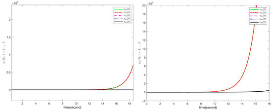
Figure 1.
Trajectories of without controllers, , .
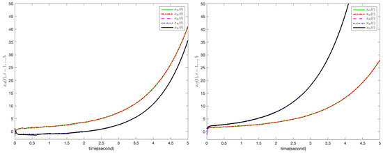
Figure 2.
Trajectories of with controllers, , .
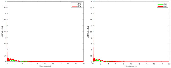
Figure 3.
Trajectories of cluster errors under controllers, .
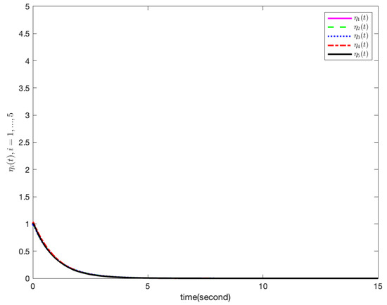
Figure 4.
Trajectories of internal dynamic functions , .
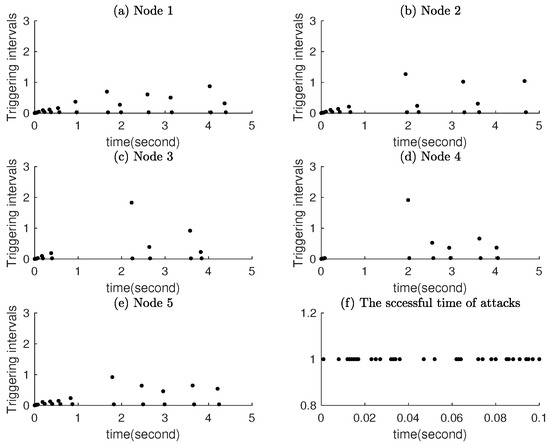
Figure 5.
Dynamic event-triggered time and the attack time.
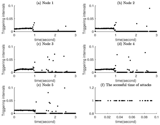
Figure 6.
Static event-triggered time and the attack time.
5. Conclusions
The secure cluster synchronization problem of CDNs under deception attacks has been investigated in this chapter. By taking into account both the effects of intermittent data transmissions under the distributed dynamic event-triggered mechanism and stochastic deception attacks, some sufficient conditions on the secure cluster synchronization performance analysis and controller design are established. Then, an illustrative example is given to show the effectiveness of the proposed theoretical methods and control schemes. In future work, we plan to explore two directions: (1) Markovian jump attack models: to capture time-varying attack probabilities (e.g., attackers may increase intensity during peak network traffic, leading to transition between ‘low-attack’ and ‘high-attack’ modes); and (2) Poisson-distributed attack models: to describe the random arrival of attack sequences. These extensions will allow us to address more complex attack behaviors while maintaining the core advantages of the dynamic event-triggered control framework proposed in this paper.
Author Contributions
Conceptualization, Y.Y. and L.L.; methodology, L.L.; software, Y.Y.; validation, L.L.; formal analysis, L.L.; investigation, Y.Y.; resources, L.L.; data curation, L.L.; writing—original draft preparation, Y.Y.; writing—review and editing, L.L.; visualization, Y.Y.; supervision, L.L.; project administration, Y.Y.; funding acquisition, L.L. All authors have read and agreed to the published version of the manuscript.
Funding
This work was funded by the Youth Doctor ’Sailing’ Project of Guangzhou Basic Research Plan for Basic and Applied Basic Research grant number 1749529.
Data Availability Statement
The original contributions presented in this study are included in the article. Further inquiries can be directed to the corresponding author.
Acknowledgments
The authors have reviewed and edited the output and take full responsibility for the content of this publication.
Conflicts of Interest
The authors declare no conflicts of interest.
References
- Hu, J.; Jia, C.Q.; Liu, H.J.; Yi, X.J.; Liu, Y.R. A survey on state estimation of complex dynamical networks. Int. J. Syst. Sci. 2021, 52, 3351–3367. [Google Scholar] [CrossRef]
- He, Z.L.; Li, C.D.; Nie, L.F. Synchronization of complex dynamical networks with saturated delayed impulsive control. ISA Trans. 2025, 157, 153–163. [Google Scholar] [CrossRef]
- Sun, J.; Guo, Y.X.; Zhang, C. Exponential synchronization of nonlinear complex dynamic networks via intermittent pinning control on time scales. Neurocomputing 2024, 578, 127375. [Google Scholar] [CrossRef]
- Wei, G.M.; Yuan, Z.Z.; Qi, W.H.; Cao, J.D.; Cheng, J.; Shi, K.B. Finite-time self-triggered synchronization for semi-Markov jump reaction-diffusion complex dynamical networks. J. Frankl. Inst. 2025, 362, 107765. [Google Scholar] [CrossRef]
- Shi, J.Y.; Zhou, P.P.; Jia, Q.; Cai, S.M. Fixed-time synchronization of multilayered complex dynamic networks via quantized variable-gain saturated control. Inf. Sci. 2024, 681, 121206. [Google Scholar] [CrossRef]
- Zhang, Y.X.; Sun, M.M.; Li, K.Z. Synchronization on complex dynamical networks via intermittently sampled-data pinning control. Physical A 2024, 654, 130109. [Google Scholar] [CrossRef]
- Chen, W.; Wang, X.P.; Ren, F.M.; Zeng, Z.G. Quasi-synchronization for variable-order fractional complex dynamical networks with hybrid delay-dependent impulses. Neural Netw. 2024, 173, 106161. [Google Scholar]
- Wang, L.; Liang, Q.Y.; She, Z.K.; Lv, J.H.; Wang, Q.G. A decomposition approach for synchronization of heterogeneous complex networks. IEEE Trans. Syst. Man Cybern. Syst. 2021, 51, 853–863. [Google Scholar] [CrossRef]
- Pecora, L.M.; Carroll, T.L. Master stability functions for synchronized coupled systems. Phys. Rev. Lett. 1998, 80, 2109–2112. [Google Scholar] [CrossRef]
- Chen, M.Y. Some simple synchronization criteria for complex dynamical networks. IEEE Trans. Circuits Syst. 2006, 53, 1185–1189. [Google Scholar] [CrossRef]
- Yao, J.; Guan, Z.H.; Hill, D.J. Passivity-based control and synchronization of general complex dynamical networks. Automatica 2009, 45, 2107–2113. [Google Scholar] [CrossRef]
- Liao, B.; Wang, Y.; Xue, J.; Zhou, Z.; Zhang, S.; Chen, X. Dynamic Clustering-Based Time Synchronization for PLC-TWACS Integrated Multimodal Power IoT in Smart Park. IEEE Syst. J. 2024, 18, 1296–1307. [Google Scholar] [CrossRef]
- Shi, T.T.; Hu, C.; Jiang, H.J.; Zhu, Q.X.; Huang, T.W. Fixed-time leaderless cluster synchronization of spatiotemporal community networks with coopetition interactions. IEEE Trans. Cybern. 2025. early access. [Google Scholar] [CrossRef] [PubMed]
- Liu, X.Y.; Ho, D.; Xie, C.L. Prescribed-time cluster synchronization of complex networks via a smooth control approach. IEEE Trans. Cybern. 2020, 50, 1771–1775. [Google Scholar] [CrossRef]
- Wu, H.F.; Liu, S.; Wang, L.C. Cluster synchronization of complex dynamic networks under pinning control via a limited capacity communication channel. Nonlinear Anal. Hybrid Syst. 2025, 55, 101547. [Google Scholar] [CrossRef]
- Liu, L.; Zhou, W.N.; Huang, C. Finite/prescribed-time cluster synchronization of complex dynamical networks with multi-proportional delays and asynchronous switching. IEEE Trans. Syst. Man Cybern. Syst. 2023, 53, 3683–3694. [Google Scholar] [CrossRef]
- Wang, X.; Park, J.H.; Yang, H.L.; Zhong, S.M. An improved impulsive control approach for cluster synchronization of complex networks with parameters mismatches. IEEE Trans. Syst. Man Cybern. Syst. 2021, 51, 2561–2570. [Google Scholar] [CrossRef]
- Zhang, J.Y.; Ma, Y.C. Output feedback pinning control for complex dynamical networks subjected to multiple attacks. Chaos Solitons Fractals 2024, 181, 114625. [Google Scholar] [CrossRef]
- Hu, T.T.; Shi, K.B. Secure synchronization control for complex dynamic networks with event-triggered communication strategy under multi-channel denial-of-service attacks. ISA Trans. 2025, 158, 50–61. [Google Scholar] [CrossRef] [PubMed]
- Li, Y.; Song, F.Y.; Liu, J.L.; Xie, X.P.; Tian, E.G.; Fei, S.M. Round Robin-based synchronization control for discrete-time complex networks with probabilistic coupling delay and deception attacks. IEEE Trans. Syst. Man Cybern. Syst. 2024, 54, 4425–4436. [Google Scholar] [CrossRef]
- Yang, N.; Chen, S.S.; Su, H. Adaptive event-triggered impulsive control for stochastic complex networks with delays under deception attacks. Nonlinear Dyn. 2025, 113, 2259–2276. [Google Scholar] [CrossRef]
- Yang, N.; Fan, X.D.; Su, H. Dynamic event-triggered delayed impulsive control for stochastic T-S fuzzy complex networks under cyber attacks. J. Frankl. Inst. 2025, 362, 107863. [Google Scholar] [CrossRef]
- Ding, D.R.; Han, Q.L.; Wang, Z.D.; Ge, X.H. Recursive filtering of distributed cyber-physical systems with attack deception. IEEE Trans. Syst. Man Cybern. Syst. 2021, 51, 6466–6476. [Google Scholar] [CrossRef]
- Rajchakit, G.; Banu, K.A.; Aparna, T.; Lim, C.P. Event-triggered secure control for Markov jump neural networks with time-varying delays and subject to cyber-attacks via state estimation fuzzy approach. Int. J. Syst. Sci. 2025, 56, 211–226. [Google Scholar] [CrossRef]
- Javanmardi, S.; Nascita, A.; Pescapè, A.; Merlino, G.; Scarpa, M. An integration perspective of security, privacy, and resource efficiency in IoT-Fog networks: A comprehensive survey. Comput. Netw. 2025. early access. [Google Scholar] [CrossRef]
- Zhou, L.L.; Huang, M.Z.; Tan, F.; Zong, G.D.; Wang, Z.; Zhuang, G.M. Fixed-time discontinuous control for cluster secure synchronization of interlayer switching networks under attacks. IEEE Trans. Autom. Sci. Eng. 2025, 22, 18848–18859. [Google Scholar] [CrossRef]
- Sakthivel, N.; Rajkumar, V.; Sabarish Kumar, V. Synchronization of a complex dynamical networks using deception attacks subject to uncertainty and disturbance estimator. Eur. J. Control 2025, 83, 101208. [Google Scholar]
- Mi, J.; Wu, H.Q.; Cao, J.D. Finite-time secure synchronization for stochastic complex networks with delayed coupling under deception attacks: A two-step switching control scheme. Inf. Sci. 2025, 691, 121647. [Google Scholar] [CrossRef]
- Xu, Z.L.; Yang, N.; Li, A.D.; Lu, J.Q. Input-to-state stability of switched network control systems under unknown deception attacks. IEEE Trans. Cybern. 2024, 54, 5483–5492. [Google Scholar] [CrossRef] [PubMed]
- Wu, Y.B.; Guo, Z.R.; Xue, L.; Ahn, C.K.; Liu, J. Stabilization of complex networks under asynchronously intermittent event-triggered control. Automatica 2024, 161, 111493. [Google Scholar] [CrossRef]
- Xu, D.S.; Wang, X.F.; Su, H. Delay event-triggered control for stability analysis of complex networks. IEEE Trans. Circuits Syst. II Express Briefs 2022, 70, 1104–1108. [Google Scholar] [CrossRef]
- Wang, H.; Yang, X.; Xiang, Z.; Tang, R.Q.; Ning, Q. Synchronization of switched neural networks via attacked mode-dependent event-triggered control and its application in image encryption. IEEE Trans. Cybern. 2022, 53, 5994–6003. [Google Scholar] [CrossRef]
- Yang, X.S.; Feng, G.Y.; He, C.T.; Cao, J.D. Event-triggered dynamic output quantization control of switched T-S fuzzy systems with unstable modes. IEEE Trans. Fuzzy Syst. 2022, 30, 4201–4210. [Google Scholar] [CrossRef]
- Wang, X.L.; Ding, D.R.; Ge, X.H.; Dong, H.L.; Han, Q.L. Neural-network-based control with dynamic event-triggered mechanisms under DoS attacks and applications in load frequency control. IEEE Trans. Circuits Syst. I Regul. Pap. 2022, 69, 5312–5324. [Google Scholar] [CrossRef]
- Zhao, B.; Shi, G.; Liu, D. Event-triggered local control for nonlinear interconnected systems through particle swarm optimization-based adaptive dynamic programming. IEEE Trans. Syst. Man Cybern. Syst. 2023, 53, 7342–7353. [Google Scholar] [CrossRef]
- Hu, T.T.; He, Z.; Zhang, X.J.; Zhong, S.M.; Shi, K.B.; Zhang, Y.Y. Adaptive fuzzy control for quasi-synchronization of uncertain complex dynamical networks with time-varying topology via event-triggered communication strategy. Inf. Sci. 2022, 582, 704–724. [Google Scholar] [CrossRef]
- Girard, A. Dynamic triggering mechanisms for event-triggered control. IEEE Trans. Automat. Control 2015, 60, 1992–1997. [Google Scholar] [CrossRef]
- Zhou, L.; Ma, Y.C.; Zou, J.H. Robust synchronization of Markovian jump complex dynamical networks under link attacks: Delay-dependent dynamic event-triggered control approach. J. Frankl. Inst. 2024, 361, 107251. [Google Scholar] [CrossRef]
- Yang, X.T.; Li, A.J.; Zhu, Q.X. Dynamic periodic event-triggered control of stochastic complex networks with time-varying delays. Neural Netw. 2025, 190, 107659. [Google Scholar] [CrossRef]
- Tang, W.; Sheng, Y.; Xiao, Q.; Huang, T.; Zeng, Z. Synchronization of complex dynamical networks on time scales via intermittent dynamic event-triggered control. IEEE Trans. Syst. Man Cybern. Syst. 2024, 54, 2897–2906. [Google Scholar] [CrossRef]
- Liu, Y.R.; Wang, Z.D.; Liu, X.H. Global exponential stability of generalized recurrent neural networks with discrete and distributed delays. Neural Netw. 2006, 19, 667–675. [Google Scholar] [CrossRef] [PubMed]


Disclaimer/Publisher’s Note: The statements, opinions and data contained in all publications are solely those of the individual author(s) and contributor(s) and not of MDPI and/or the editor(s). MDPI and/or the editor(s) disclaim responsibility for any injury to people or property resulting from any ideas, methods, instructions or products referred to in the content. |
© 2025 by the authors. Licensee MDPI, Basel, Switzerland. This article is an open access article distributed under the terms and conditions of the Creative Commons Attribution (CC BY) license (https://creativecommons.org/licenses/by/4.0/).