Article

Multi-Objective Optimization of Design Parameters to Improve Dynamic Performances of Distributed Actuation Mechanism

1
Department of Mechanical Engineering, Keimyung University, Daegu 42601, Republic of Korea
2
Department of Automotive Engineering, Keimyung University, Daegu 42601, Republic of Korea
*
Author to whom correspondence should be addressed.
Mathematics 2025, 13(23), 3773; https://doi.org/10.3390/math13233773
Submission received: 29 October 2025 / Revised: 17 November 2025 / Accepted: 19 November 2025 / Published: 24 November 2025
(This article belongs to the Special Issue Advanced Modeling and Design of Vibration and Wave Systems)

Abstract

The distributed actuation mechanism (DAM) is inspired by the motion of biological muscles and enables efficient modulation between speed and force through a variable gearing concept. This study proposes an advanced modeling-based multi-objective optimization framework that enhances the dynamic performance of a DAM-based manipulator by simultaneously improving its end-effector velocity and payload capacity. The kinematic and dynamic characteristics of the DAM are mathematically modeled to capture the interactions among design parameters, and a high-fidelity multibody dynamics model is developed using RecurDyn. Then, a sequential quadratic programming (SQP) algorithm implemented in MATLAB is employed to perform optimization under geometric and physical constraints. The results demonstrate that the proposed optimization method achieved increases of approximately 46.5% in maximum velocity and over 40% in maximum payload, confirming the effectiveness of the advanced modeling-based optimization strategy. It was also found that link-length ratios and hinge offsets play critical roles in determining the DAM’s dynamic behavior. The proposed framework provides a systematic and practical approach for integrating mathematical modeling with design optimization and offers valuable guidelines for improving the structural design and performance of distributed-actuation-based robotic manipulators.

1. Introduction

In recent years, the design of robotic systems has increasingly focused on achieving a high dynamic performance while maintaining stability, precision, and energy efficiency through advanced modeling and design optimization. Industrial robots, medical manipulators, and service robots exhibit complex and nonlinear dynamic behaviors, and are expected to satisfy complex requirements, such as speed, force, stiffness, and efficiency under various operating environments and load conditions. To address these challenges, it is essential to develop an analytically rigorous model that accurately represents the kinematic and dynamic characteristics of robotic systems, and to apply a numerical optimization framework that systematically analyzes the interactions among design parameters based on that model. Recent studies that integrate mathematical modeling with numerical optimization have demonstrated the potential to improve both model accuracy and design efficiency in complex engineering systems [1,2,3].
Optimal design is a methodology for determining design parameters that maximize the system performance within given physical and kinematic constraints [4,5]. When a single performance index is considered, it is referred to as single-objective optimization and has been successfully applied in various robotic applications, such as improving operation speed [6], enhancing structural stiffness [7], and minimizing positioning errors in medical robots [8,9,10]. However, single-objective optimization often focuses on a single performance aspect, making it difficult to address the tradeoffs between multiple conflicting objectives, potentially resulting in suboptimal solutions.
To overcome these limitations, multi-objective optimization (MOO) has attracted increased attention in recent years [11,12]. MOO considers multiple conflicting objectives, such as speed and force, accuracy and computation time, and torque and mass, and derives a set of Pareto-optimal solutions that represent the best possible trade-offs among these competing performance metrics [13,14,15]. This approach has been applied in various areas of robotics, including path planning [16], control strategy development [17], and mechanical design optimization [18]. For example, Wei et al. [19] proposed a multi-objective particle swarm optimization (PSO) method to simultaneously minimize energy consumption and task completion time in cooperative robotic systems. Ajeil et al. [20] introduced a hybrid PSO-modified frequency bat (PSO–MFB) algorithm that effectively enhanced the path planning performance of autonomous mobile robots.
Manipulators with redundant degrees of freedom (DOFs) are particularly suitable for multiobjective optimization because they can achieve identical end-effector trajectories through multiple joint configurations. This redundancy provides some degree of flexibility in the design process and enables the simultaneous improvement of various performance indices, including manipulability [21], energy efficiency [22], load distribution, obstacle avoidance [23], and grasping performance [24].
Most previous studies on robotics have focused on dynamic control–oriented approaches such as control performance, actuation-force distribution, and trajectory planning [1,2]. Although these methods have proven effective in improving system stability and control accuracy, they have a fundamental limitation in that they do not sufficiently reflect the influences of structural design variables or geometric configurations on the overall system performance. Accordingly, recent studies have actively explored advanced modeling-based design approaches that integrate the kinematic structure and physical parameters of robots from the modeling stage to enable performance prediction and optimization [3,25].
Meanwhile, the distributed actuation mechanism (DAM), which emulates the motion principles of biological muscles, has been proposed as a novel actuation structure that enables efficient transitions between high-speed and high-force operations by applying a variable gearing concept [26]. Shin and Kim [27] applied the DAM to a finger-type manipulator and experimentally verified its superior grasping performance. Subsequent studies employed MOO to analyze variations in end-effector velocity according to payload changes, and through comparisons with the conventional joint actuation mechanism (JAM), demonstrated the superior performance of the DAM.
This study proposes an advanced modeling-based design optimization procedure that simultaneously improves the end-effector velocity and payload capacity of a DAM. First, the kinematic and dynamic characteristics of the DAM were mathematically modeled to analytically formulate the interactions between the design variables and system behavior in an interpretable form. Based on the results of this mathematical model, the multibody dynamics analysis software RecurDyn 2025 was utilized to precisely model the kinematic structure of the DAM and to construct a high-fidelity simulation model that reflects realistic operating conditions. Subsequently, a MOO algorithm was performed in conjunction with MATLAB R2024a. The optimal design combinations that enhanced the dynamic performance of the DAM were derived by numerically analyzing the interactions among the design variables, constraints, and objective functions. The results of this study are expected to provide practical guidelines for the integrated application of mathematical modeling and numerical design optimization techniques in the structural design stage of robotic manipulators.

Contributions of This Study

The main contributions and innovations of this study are summarized as follows:
(1)
Mathematical modeling and optimization formulation.
This study establishes a unified mathematical framework that explicitly formulates the kinematic, dynamic, and geometric relationships of a multi-DOF DAM-based manipulator. The framework enables simultaneous improvement of end-effector velocity and payload capacity through a rigorously defined multi-objective optimization problem.
(2)
Co-simulation-based optimization architecture.
A coupled RecurDyn–MATLAB optimization pipeline is developed, allowing high-fidelity multibody dynamic analysis to be integrated directly with a MATLAB-based SQP multi-objective optimizer. This co-simulation approach provides a systematic method for exploring feasible design combinations under geometric and motor constraints.
(3)
Quantitative verification of structural advantages of DAM.
The effectiveness of the proposed design methodology is demonstrated through dynamic simulations and manipulability-based evaluation. The results quantitatively confirm that the optimized DAM configuration enhances both speed and load-handling performance, highlighting the structural benefits of variable actuation-point mechanisms.
The remainder of this paper is organized as follows. Section 2 presents the modeling and MOO formulation of the DAM, including its kinematic structure, design parameters, and mathematical constraints. Section 3 describes the numerical analysis and optimization results and verifies the effectiveness of the proposed framework through a simulation-based performance evaluation. Finally, Section 4 provides conclusions and outlines directions for future research.

2. Modeling and Multi-Objective Optimization Formulation of the DAM

This section presents the mathematical modeling of the DAM based on its kinematic structure and the formulation of the MOO problem developed using this model. The DAM, which is inspired by the motion principles of biological muscles, consists of two sliders, front and rear, that are connected by a connecting rod (Figure 1).
This structure enables distributed actuation, allowing multiple actuators to be placed along a single link, and making it possible to adaptively adjust the torque distribution and gear ratio in response to varying load conditions or working environments.

2.1. Kinematic Characteristics and Design Parameters of DAM

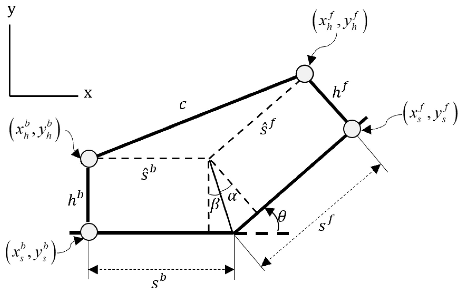
Figure 2 presents the mathematical derivation of the modeling process for the single-joint of DAM, which can be expressed as follows:
x h f = x s f h f cos ( π 2 θ ) y h f = y s f + h f sin ( π 2 θ ) x s f = s f cos θ y s f = s f sin θ
x s f and y s f represent the x- and y-coordinates of the slider position measured from the origin of a single joint. The superscript f denotes the front slider, while the subscript s indicates the position of the slider attached to the link. Similarly, x h f and y h f denote the coordinates of the contact point where the connecting rod is joined to the slider through the hinge joint, where the subscript h is used to describe the offset distance introduced by the hinge joint. The connecting rod that links the two sliders can be represented as follows:
c = s ^ f + s ^ b 2 s ^ f s ^ b cos π θ w h e r e s ^ f = s f h f tan α s ^ b = s b h b tan β α = atan h f h b cos θ sin θ β = θ α
DAM possess several unique mechanical features.
(1)
The use of multiple actuators on a single link provides redundant DOFs and offers flexibility in dynamic performance optimization.
(2)
The actuator torque can be modulated solely by adjusting the slider position, enabling speed–force conversion without changing the joint positions.
(3)
This mechanism exhibits fault tolerance because the function can be maintained through alternative actuation paths in the event of actuator failure.
(4)
Variable gearing allows real-time adaptation to load variations, thereby improving energy efficiency and operational stability.
(5)
The overall system performance is determined by parameters such as the slider position, velocity, and hinge offset, emphasizing the need to optimize these design variables.
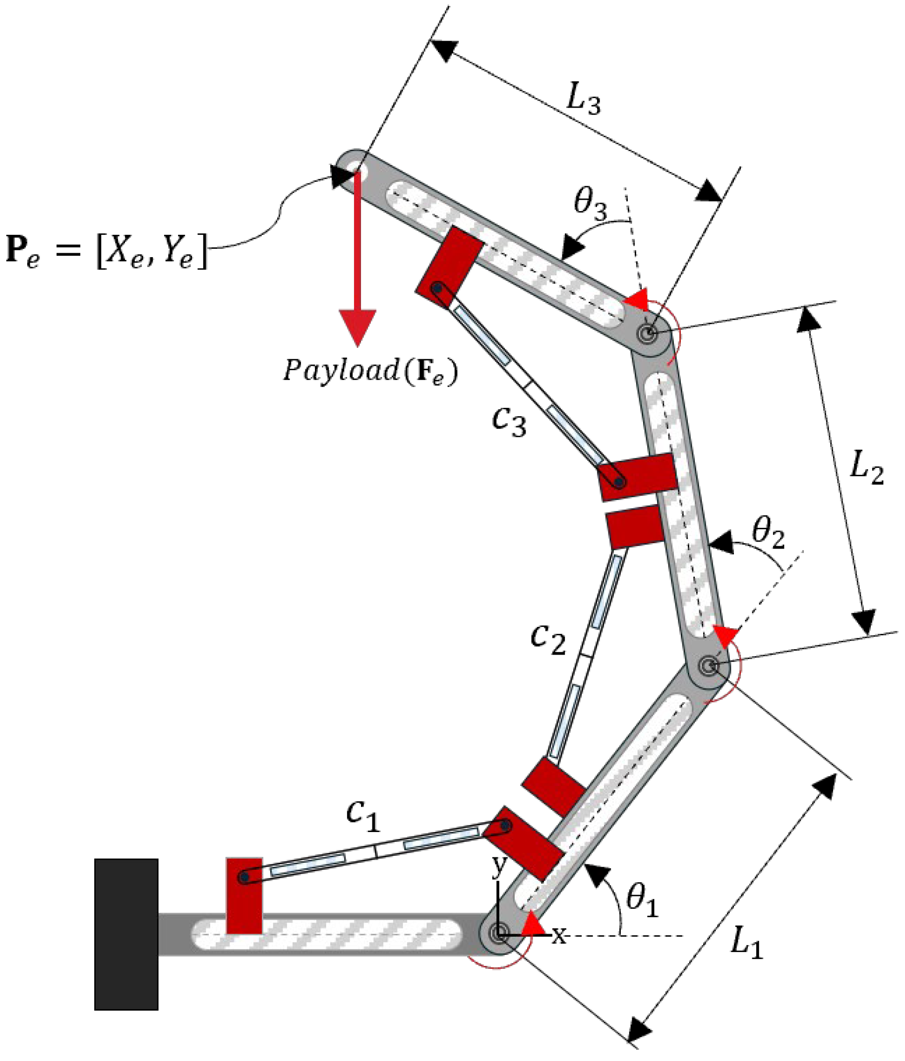
A schematic of a DAM-based 3-DOF manipulator is presented to represent these features (Figure 3). Each joint comprised front and rear sliders, connecting rods, and links. The length of each connecting rod varies with the slider position, and the hinge offset, defined as the perpendicular distance between the rod connection point and the link axis, plays a crucial role in the kinematic performance of the manipulator.
It is important to note that in this study, the hinge offset was included as an independent design variable to handle kinematic singularities.
For example, to prevent the connecting rod and the link axis from becoming collinear—which would cause a kinematic singularity—a lower bound constraint of 10 mm was imposed on the hinge offset. In addition, the joint angle limits were restricted to the range of 20° to 90°, ensuring that all simulations were performed within configurations free from singularities.
This constraint-based modeling approach can also be regarded as one of the structural limitations inherent to the current DAM configuration.
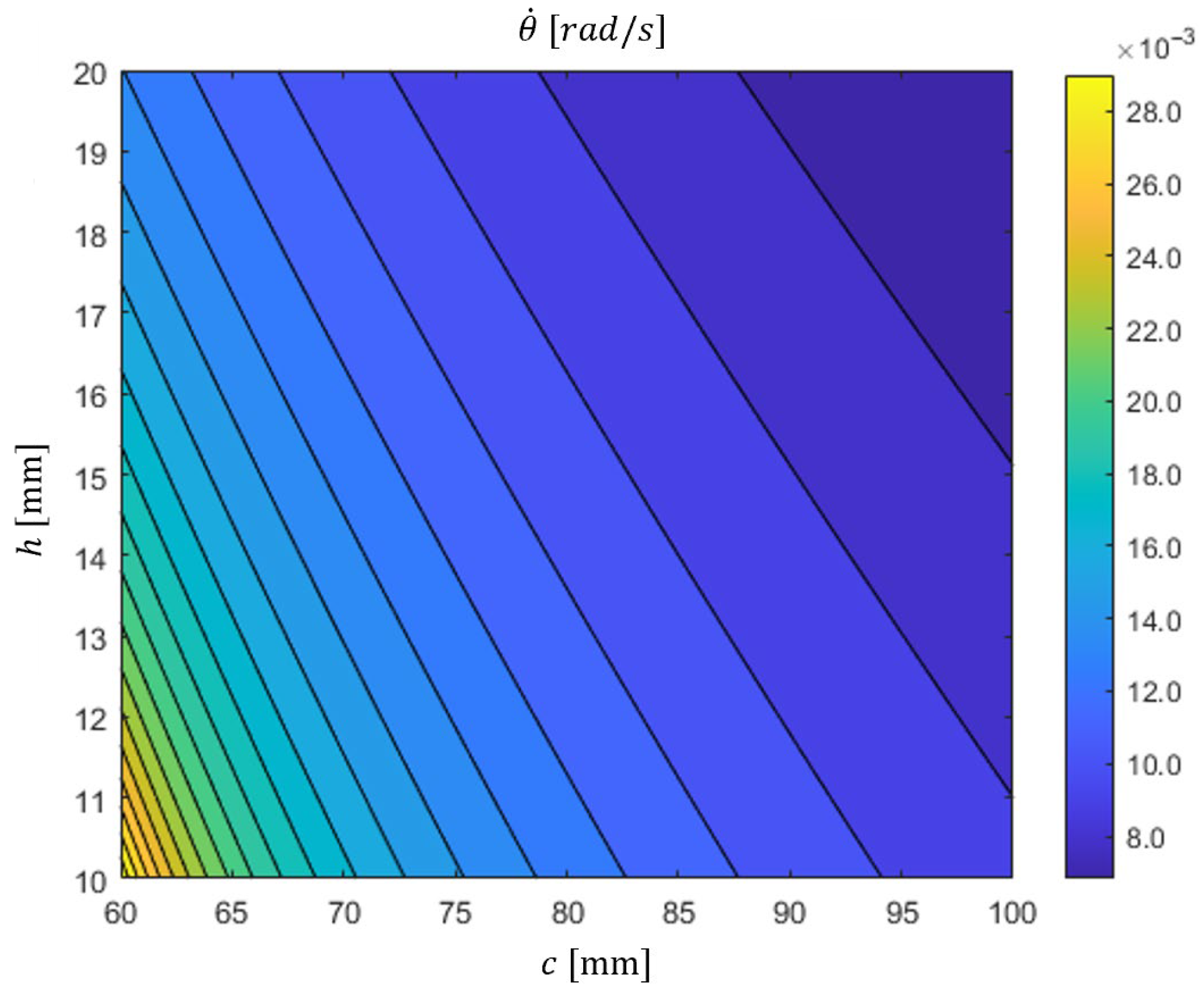
To investigate a relationship between the connecting rod length and hinge offset, the angular velocity of the single-joint can be derived [26], as follows:
θ ˙ = ( s h tan θ 2 ) ( s ˙ + s ˙ b cos θ ) + ( s b h tan θ 2 ) ( s ˙ cos θ + s ˙ b ) h cos θ ( s + s b ) + sin θ ( s s b h 2 )
Figure 4 shows a contour plot of the joint angular velocity as a function of the connecting rod length and hinge offset. Owing to their nonlinear relationships, both parameters were selected as independent design variables.
In addition, the link lengths (l1, l2, l3) determine the workspace of the manipulator and the velocity–force characteristics; therefore, the ratios among the link lengths were included as essential optimization variables. All the design variables and their limits are summarized in Table 1, and a more detailed explanation of each parameter and its role in the optimization process is provided in Section 2.3 (Multi-Objective Optimization Formulation).

2.2. Definition of Constraints

(1)
Equality Constraints
The first equality constraint e1 ensures that the sum of the three link lengths remains constant, thereby maintaining the manipulator’s total size and workspace. This constraint was introduced to analyze the impact of the relative proportions of link lengths on the dynamic performance of the DAM, while keeping the overall manipulator length fixed.
e 1 = l 1 + l 2 + l 3 = L c o n s t
where Lconst is the total manipulator length.
The second equality constraint e2 ensures that the velocity vector of the end effector aligns with the desired reference direction, which allows the motion to be constrained along a specific working orientation (e.g., horizontal, vertical, or diagonal).
Mathematically, this can be expressed as
e 2 = v e d k = v e d k
where dk is the target direction unit vector, which is defined as:
d k = [ cos α ,   sin α ] T
and α represents the orientation angle with respect to the x-axis, ranging from 0° to 360°.
(2)
Inequality Constraints
The first inequality constraint g1 limits the total motor power applied to the front and rear sliders such that it does not exceed the total maximum power of the initial DAM configuration. The constraint g 1 can be formulated as:
P total ( i = 1 3 P i , max f + j = 1 3 P j , max b ) 0
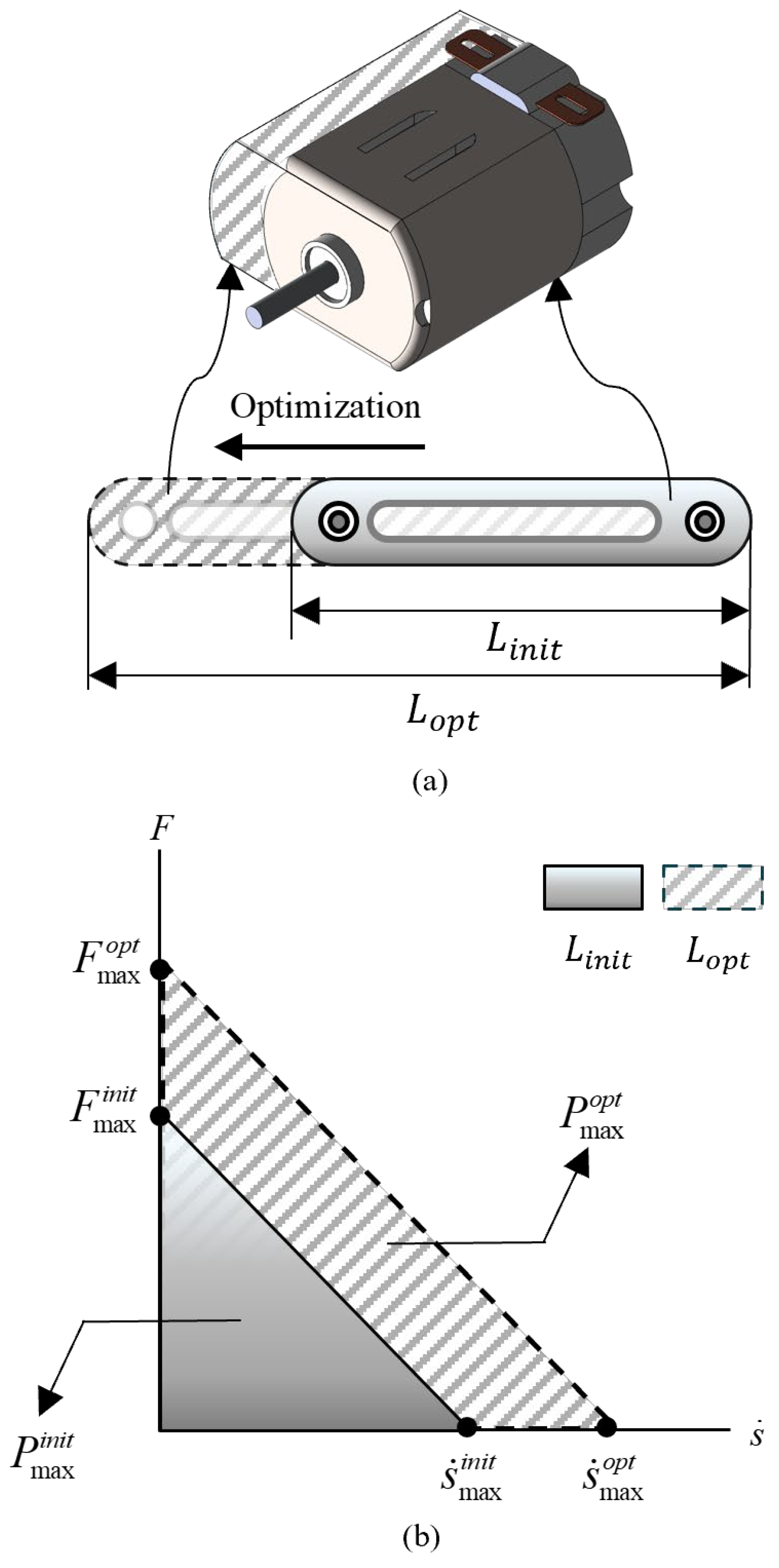
In this expression, P t o t a l denotes the total maximum power of the six available motors in the baseline DAM model. P i , m a x f and P j , m a x b represent the sum of the maximum powers of the motors used in the optimized model. This condition ensures a fair comparison between the initial and optimized models, maintaining an equal total motor power capacity. The power of each DC motor was calculated using the area under its linear torque–speed characteristic curve (Figure 5b), which is expressed as
C ( i ) = ( P max f 1 + P max f 2 + P max f 3 + P max b 1 + P max b 2 + P max b 3 ) P max i n i t w h e r e   P max i n i t = 6 ( s ˙ max i n i t F max i n i t 1 2 )
Generally, as the link length increases, the mass of the link also increases. Therefore, in this study, it is assumed that the required motor power increases proportionally with the link length (Figure 5a). Consequently, as illustrated in Figure 5b, the motor performance enhancement ratio follows the link-length increment ratio and corresponds to an increase in the area under the DC motor’s performance curve. This relationship can be expressed as:
L max i n i t : P max i n i t = L max o p t : P max o p t
Here, the superscript init denotes the initial configuration, while adv represents the advanced (optimized) configuration.
In addition, the slope of the torque–speed characteristic curve of the DC motor remained constant within the four-quadrant operating region.
F max i n i t s ˙ max i n i t = F max o p t s ˙ max o p t
Considering Equations (9) and (10), as well as the fact that the area under the performance curve in Figure 3 represents the output power of the motor, the maximum velocity of the slider can be expressed as follows:
s ˙ max o p t = 2 P max i n i t F max i n i t s ˙ max i n i t
s ˙ m a x o p t acts as a new constraint on the design variable s ˙ , and it further influences the subsequent inequality constraints g 2 and g 3 .
The second and third inequality constraints, g2 and g3, were introduced to ensure the physical feasibility of the motor operation.
These constraints limit the slider’s output force and velocity to operate within the four-quadrant performance curve of the DC motor, and can be expressed as follows:
g 2 = F j ± F max s ˙ max s ˙ j ± F max 0 g 3 = F j b ± F max s ˙ max s ˙ j b ± F max 0
Here, superscript b denotes the parameters corresponding to the rear position within a single joint, and subscript j indicates the joint number.
F j and F m a x represent the slider thrust and the maximum slider thrust at joint j, respectively; s ˙ j and s ˙ m a x denote the slider velocity and maximum slider velocity, respectively.

2.3. Multi-Objective Optimization Formulation

The enhancement of the dynamic performance of the DAM is defined as a MOO problem that involves two conflicting objectives: maximizing the end-effector velocity and payload capacity.
In this study, the ε-constraint method was adopted, where the primary objective function f 1 is minimized, while the secondary objective f 2 is imposed as a constraint [28].
This approach enables the derivation of a Pareto-optimal set that represents the trade-off between the two objectives.
Find x 1 , x 2 , , x n To   minimize f 2 ( x ) subject   to f 1 ( x ) ε m m = 1 , 2 , , M g j ( x ) 0 j = 1 , 2 , , J h k ( x ) = 0 k = 1 , 2 , , K x i ( L ) x i x i ( L ) i = 1 , 2 , , n
where ε m represents the lower bound for the payload capacity, and gj and ek denote the inequality and equality constraints, respectively.
In this study, the end-effector velocity (f1) was directly defined as the primary optimization objective, while the payload capacity (f2) was imposed as a design constraint in the form of εf1.
Using this formulation, the quantitative influence of the structural design variables on the overall performance was analyzed.
Finally, the MOO problem for the distributed actuation-mechanism-based multi-DOF manipulator can be expressed as shown in Equation (14).
In this formulation, f1 corresponds to the end-effector velocity, which is the primary optimization objective, while f2 represents the payload capacity, imposed as a constraint to ensure feasible mechanical operation under loading conditions.
Considering the kinematic relationships, dynamic constraints, and physical bounds of the design variables, the full optimization problem can be summarized as follows:
Find θ 1 ,   s 1 ,   s 1 b ,   s   ˙ 1 ,   s   ˙ 1 b ,   s 2 ,   s 2 b ,   s   ˙ 2 ,   s   ˙ 2 b ,   s 3 ,   s 3 b ,   s   ˙ 3 ,   s   ˙ 3 b ,   h 1 ,   h 1 b ,   h 2 ,   h 2 b ,   h 3 ,   h 3 b ,   x 1 ,   y 1 ,   x 2 ,   y 2 To   maximize f 1 = v e Subject   to f 2 = F e ε i i = 1 , , N e 1 = l 1 + l 2 + l 3 = 357 e 2 = v e d k = v e d k k = 1 , , M g 1 = P t o t a l ( i = 1 3 P i , max f + i = 1 3 P i , max b ) 0 g 2 = F j ± F max s ˙ max s ˙ j ± F max 0 j = 1 , 2 , 3 g 3 = F j b ± F max s ˙ max s ˙ j b ± F max 0 j = 1 , 2 , 3 10   mm h j 20   mm j = 1 , 2 , 3 10   mm h j b 20   mm j = 1 , 2 , 3 37   mm s j 77   mm j = 1 , 2 , 3 37   mm s j b 77   mm j = 1 , 2 , 3 14   mm / s s ˙ j 14   mm / s j = 1 , 2 , 3 14   mm / s s ˙ j b 14   mm / s j = 1 , 2 , 3 60   mm c j 100   mm j = 1 , 2 , 3 114   mm ( x 1 ) 2 + ( y 1 ) 2 200   mm 87   mm ( x 2 x 1 ) 2 + ( y 2 y 1 ) 2 129   mm 80   mm ( x e x 2 ) 2 + ( y e y 2 ) 2 129   mm
The design variables considered in this study are summarized as follows:
s j , s j b : Positions of front and rear sliders in the j-th joint.
s ˙ j , s ˙ j b : Velocities of front and rear sliders in the j-th joint.
h j ,   h j b : Hinge offsets of front and rear sliders in the j-th joint.
c j : Length of connecting rod in the j-th joint.
θ j : Rotational angle of the j-th joint.
x 1 , y 1 : End coordinates of the first link.
x 2 , y 2 : End coordinates of the second link.
e 1 : Equality constraint on the overall link length ratio
e 2 : Equality constraint for controlling motion in the target direction
g 1 : Inequality constraint for equalizing the maximum motor power between the initial and improved models
g 2 , g 3 : Inequality constraint to prevent exceeding the available operating range of the motor
The end-effector position ( x e , y e ) was fixed for the analysis, and the geometric relationship between the links was defined as
l 1 = ( x 1 ) 2 + ( y 1 ) 2 l 2 = ( x 2 x 1 ) 2 + ( y 2 y 1 ) 2 l 3 = ( x e x 2 ) 2 + ( y e y 2 ) 2
This mathematical formulation provides the foundation for evaluating the influence of the kinematic configuration and geometric proportions of the DAM on its overall dynamic behavior under varying operational conditions.
The first objective function ( f 1 ) represents the magnitude of the manipulator’s end-effector velocity. The end-effector velocity data were obtained from dynamic simulations performed in RecurDyn and exported as a.txt file. These data were then imported into MATLAB, where a custom script was implemented to compute the velocity component in the desired direction by taking the dot product with the basic direction vector ( d k ).
The second objective function ( f 2 ) corresponds to the payload capacity acting at the manipulator’s end-effector. Since f 1 exhibits a trade-off relationship with f 2 , the ε-constraint method, one of the common multi-objective optimization techniques, was employed.
Using this approach, f 2 was formulated as a constraint, and the Pareto front was obtained to identify the optimal trade-off between speed and load capacity.

3. Numerical Analysis and Optimization Results

This section presents the results of the numerical analysis performed to verify the effectiveness of the proposed MOO framework for the DAM.
Optimization was conducted using MATLAB in conjunction with RecurDyn using a sequential quadratic programming (SQP) algorithm.
The objectives were to maximize the end-effector velocity and payload capacity while satisfying all geometric and physical constraints described in Section 2.

3.1. Optimization Setup

To ensure a consistent evaluation, the initial configuration of the DAM was modeled using the following parameters: the link lengths were set to l1 = 114 mm, l2 = 114 mm, and l3 = 129 mm, and the total manipulator length was fixed according to the equality constraint of Equation (4).
For the optimization, eight directional vectors were defined at 45° intervals to represent different end-effector motion directions.
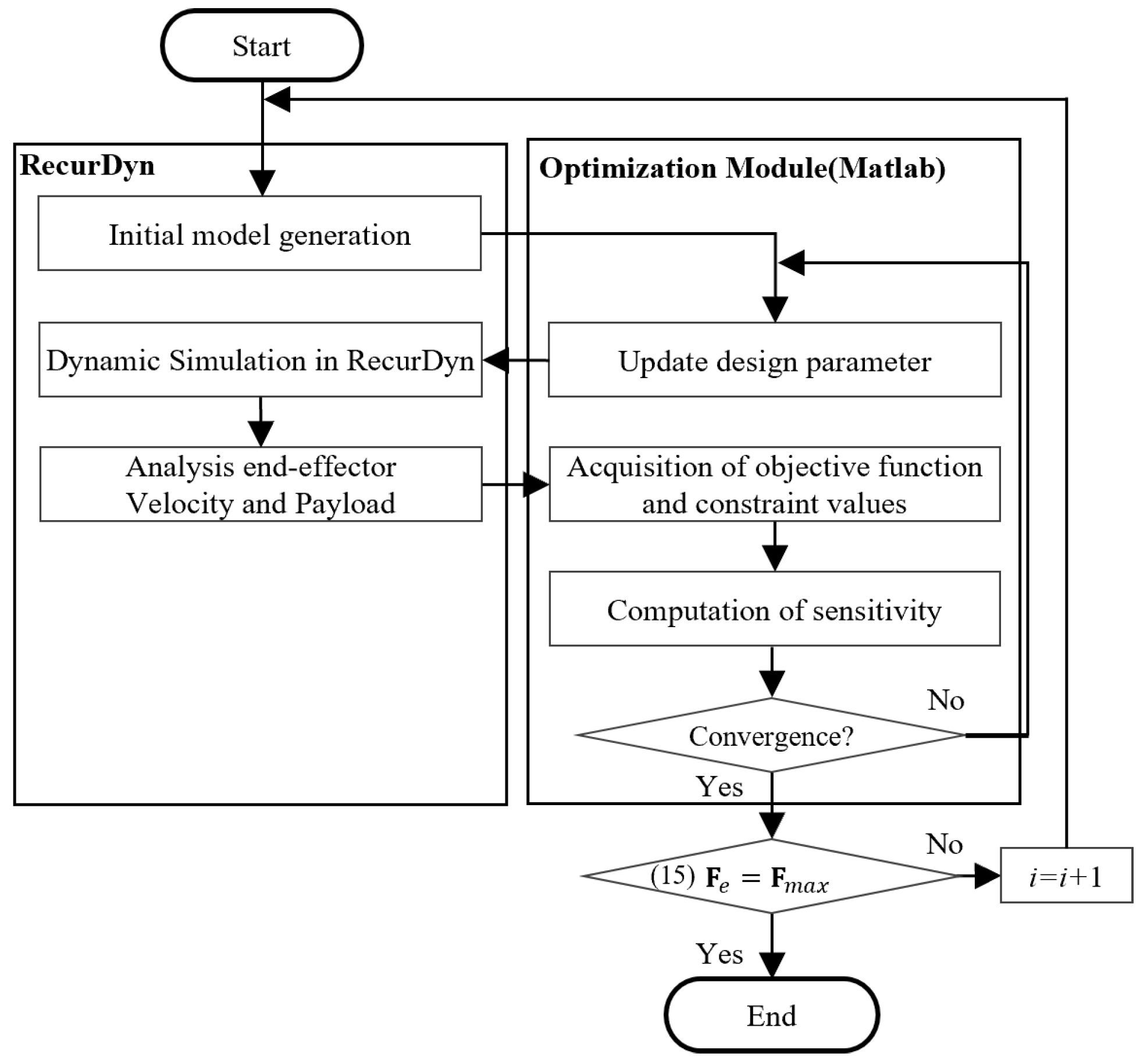
The optimization procedure employed in this study consists of the steps illustrated in Figure 6.
(1)
Initialization of design variables, including slider positions, velocities, hinge offsets, and link-length ratios.
(2)
A dynamic analysis was performed using RecurDyn to compute the end-effector velocity and payload.
(3)
Evaluation of the objective functions and constraints was performed using MATLAB.
(4)
Iterative improvement of objective functions and verification of constraint satisfaction using the SQP algorithm.
(5)
Extraction of Pareto-optimal solutions representing the trade-off between performance objectives.
This procedure was designed to explore the optimal structural combinations that maximize the dynamic performance of the DAM, while simultaneously accounting for the interactions among the design variables.

3.2. Optimization Convergence Characteristics

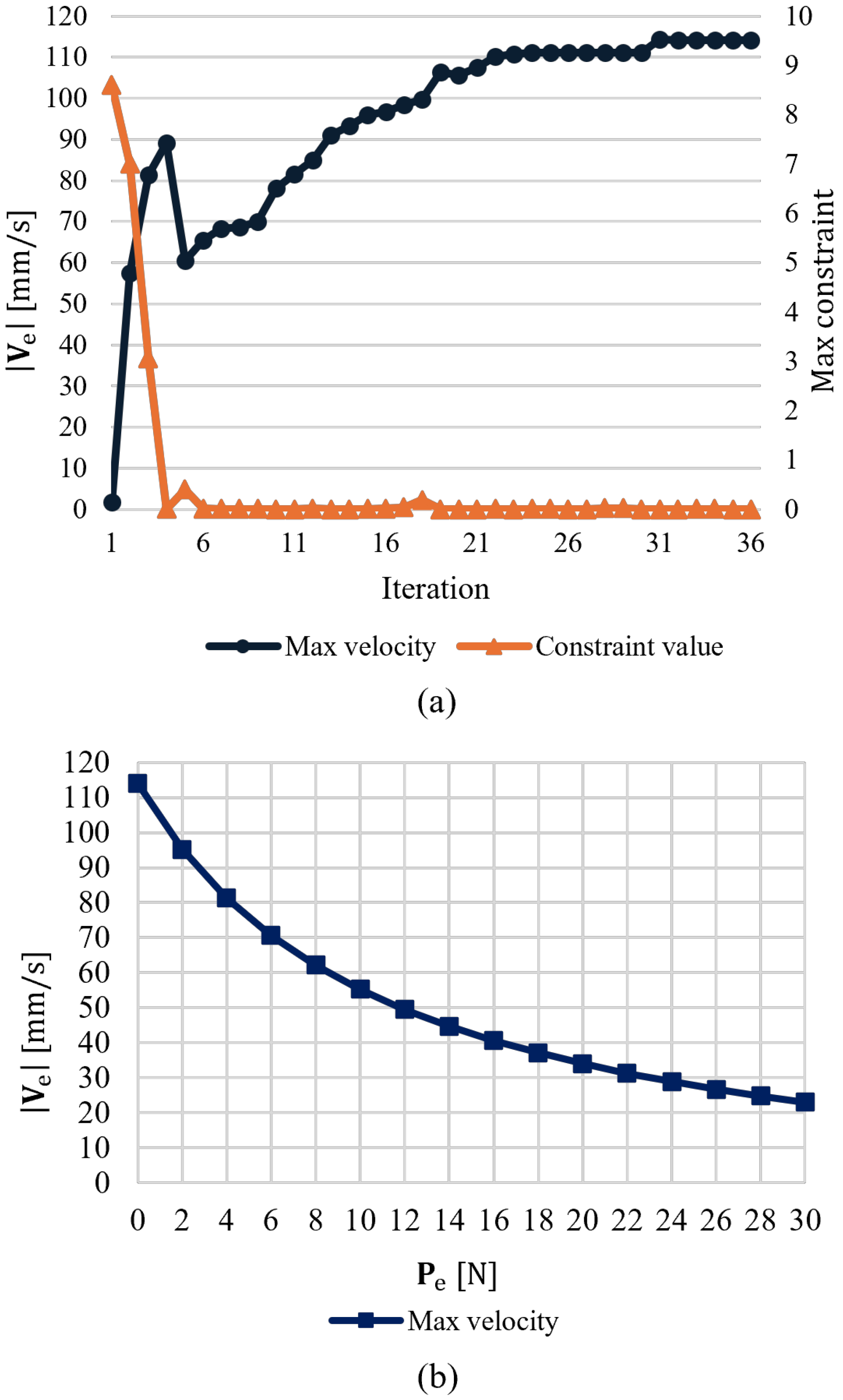
Figure 7a shows the optimization history obtained at the end-effector position p 1 = 100,150 with the motion direction aligned to the vector d = [ 0,1 ] T and no payload applied. The optimization converged to a maximum end-effector velocity of approximately 114.4 mm/s, after 36 iterations, with each iteration involving the evaluation of 22 design parameters.
Figure 7b shows the Pareto-optimal solutions obtained from the MOO at the same end-effector position. The X-axis represents the available payload of the distributed actuation mechanism, ranging from 0 to 30 N, whereas the Y-axis indicates the maximum velocity corresponding to each payload level. The results clearly demonstrate the trade-off between the velocity and load, showing that the DAM can dynamically adjust the force–velocity conversion efficiency through its variable gearing effect.
Moreover, despite the nonlinear relationship between the velocity and load, the SQP algorithm produced a stable distribution of Pareto-optimal solutions under the given constraints. This indicates that the SQP approach effectively suppresses convergence to the local optima within the design variable space.

3.3. Optimization Results and Performance Analysis

Figure 8 presents a comparative performance plot based on the five scenarios evaluated at three different end-effector positions ( p 1 , p 2 , p 3 ). The scenarios are defined as follows:
(1)
When no payload is applied ( P = 0   N ), the maximum velocity of the initial DAM.
(2)
When the maximum payload is applied ( P = P m a x i n i t ), the maximum velocity of the initial DAM.
(3)
When no payload is applied ( P = 0   N ), the maximum end-effector velocity of the DAM obtained through design parameter optimization.
(4)
When the maximum payload is applied ( P = P m a x o p t ), the maximum end-effector velocity of the DAM obtained through design parameter optimization.
(5)
For comparison with the initial DAM, the maximum end-effector velocity of the optimized DAM under the same payload conditions as those in the initial configuration.
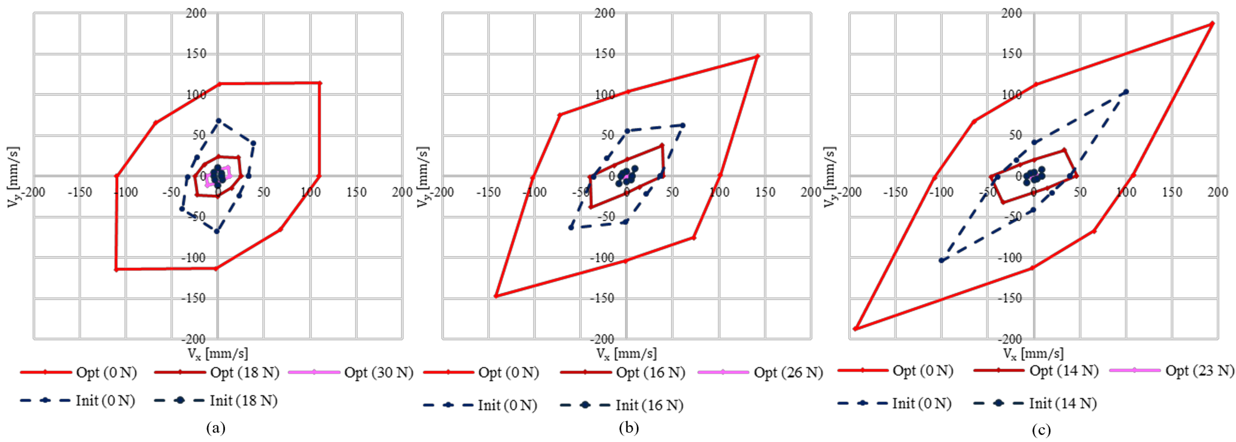
Figure 8. Optimization results at three end-effector positions. (a) p1 = (−100 mm, 150 mm), (b) p2 = (−100 mm, 200 mm), and (c) p3 = (−100 mm, 250 mm).
Mathematics 13 03773 g008
As shown in Figure 8, a visual evaluation of the maximum dynamic performance across the five scenarios reveals that the optimized performance plot exhibits an octagonal shape. This shape results from performing optimization for eight fundamental direction vectors (α = 0°, 45°, 90°, …, 315°).
As shown in the graph, the end-effector velocity of the DAM gradually increased as the end-effector position moved from p1 to p3. This indicates that as the manipulator posture increased, the linear velocity of the end effector tended to have a corresponding improvement.
At position p3, the optimized design parameters achieved a maximum velocity of 269.41 mm/s, representing an improvement of approximately 46.54% compared to the initial configuration.
In contrast, the maximum payload was highest at position p1. When design parameter optimization was applied, the payload capacity increased by approximately 12 N, reaching 30 N. This result demonstrates that the proposed structural parameter optimization not only enhances the velocity performance but also yields a significant improvement in the load-bearing capability. In other words, the proposed DAM design effectively alleviates the trade-off between velocity and load, achieving a balanced enhancement of both performance indices.
Table 2 summarizes the optimization results for the evaluated motion directions. These findings quantitatively confirm that the link-length ratios and hinge offsets of the DAM substantially influence the dynamic performance at each end-effector position. Table 2 provides key numerical evidence that supports the validity of the proposed advanced modeling-based design optimization approach.
Table 3 present the detailed optimization results obtained at the end-effector position p3, along with the variations in the design parameter, namely the link-length ratios. In the initial configuration, the three link lengths were set to 114, 114, and 129 mm. After optimization, the link lengths were readjusted, resulting in a change in the geometric proportions of the overall structure. This structural modification enhanced both the velocity transmission efficiency and manipulability of the manipulator, thereby enabling simultaneous improvements in the maximum end-effector velocity and available payload capacity.
In particular, the results confirmed that the maximum velocity of the DAM reached 191.55 mm/s, representing an improvement of approximately 54% compared to the initial design. This finding indicates that the link-length ratio directly affects the dynamic behavior of the manipulator and that the overall structure of the DAM is highly sensitive to its geometric configuration. Therefore, the precise determination of kinematic design parameters, including the link ratios, is a key factor that significantly influences the enhancement of the dynamic performance of the DAM.
Interestingly, the optimized link-length ratio exhibited a qualitatively similar pattern to the segmental length distribution of the human finger phalanges [29]. However, the quantitative proportions partially differed because of the distinct design objectives and constraints considered in this study.
The results demonstrate that variations in link-length ratios have a quantifiable impact on the dynamic performance of the DAM and indicate that the proportion-based optimization principles observed in biomechanical structures can also be effectively applied to robotic mechanism design.

4. Conclusions

This paper proposes an advanced modeling-based multi-objective optimization procedure to enhance the dynamic performance of a Distributed Actuation Mechanism (DAM). The kinematic and dynamic characteristics of the DAM were mathematically modeled to establish a structural model capable of quantitatively analyzing the interactions among design parameters. Subsequently, a high-fidelity dynamic analysis using RecurDyn was integrated with a Sequential Quadratic Programming (SQP) optimization algorithm in MATLAB to determine the optimal combination of design variables, considering the tradeoff between the end-effector velocity and payload capacity. The optimization results revealed that the maximum velocity of the DAM increased by approximately 46.5%, whereas the maximum payload improved by more than 40% compared to the initial design. It was confirmed that kinematic design parameters, such as link-length ratios and hinge offsets, play a crucial role in improving the dynamic performance. Interestingly, the optimized link length ratio exhibited a pattern similar to that of the human finger phalanges (proximal–middle–distal), suggesting that the biomechanically efficient structure of human motion can also be reflected in the robotic mechanism design. The findings of this study demonstrate the feasibility of a structural optimization strategy that simultaneously considers speed–load balance in the design stage of DAMs.
Furthermore, the proposed modeling-based optimization framework provides practical design guidelines that can be applied to various robotic manipulators and service robots. Importantly, it serves as a theoretical foundation for determining the kinematic design parameters to enhance the dynamic performance of complex multi-degree-of-freedom robotic systems. It is expected that the findings of this study will contribute to improving energy efficiency and trajectory planning of the DAM through future path optimization.
Despite the effectiveness of the proposed modeling framework and optimization strategy, this study has several inherent limitations.
First, the DAM-based manipulator model was formulated under the assumption of steady-state conditions, focusing primarily on evaluating the geometric gain and dynamic performance improvements resulting from variations in slider positions.
As a result, the model does not account for transient coupling between multiple actuators mounted on the same link, nonlinear dynamic interactions between the actuators and the link, or the dynamic response characteristics arising from time-varying control inputs. These factors may have a significant influence on the actual dynamic behavior of a DAM-based robotic system, particularly during high-speed maneuvers or rapid load transitions. Therefore, future research will aim to extend the present model by incorporating transient coupling effects and developing a more comprehensive dynamic representation.
Based on this enhanced model, advanced control strategies—such as adaptive control and vibration-suppression control—will be investigated to improve the overall stability and dynamic performance of DAM-driven manipulators.

Author Contributions

Conceptualization, J.H.K. and I.H.J.; methodology, J.H.K. and I.H.J.; software, J.H.K. and I.H.J.; validation, J.H.K. and I.H.J.; formal analysis, J.H.K. and I.H.J.; investigation, J.H.K. and I.H.J.; resources, J.H.K. and I.H.J.; data curation, J.H.K. and I.H.J.; writing—original draft preparation, J.H.K. and I.H.J.; writing—review and editing, J.H.K. and I.H.J.; visualization, J.H.K. and I.H.J.; supervision, J.H.K.; project administration, J.H.K. and I.H.J.; funding acquisition, J.H.K. and I.H.J. All authors have read and agreed to the published version of the manuscript.

Funding

This research was supported by the Bisa Research Grant of Keimyung University in 2022 (Project No: 20220239).

Data Availability Statement

The data presented in this study are available on request from the corresponding author to protect the integrity of an ongoing study.

Conflicts of Interest

The authors declare no conflicts of interest.

Abbreviations

The following abbreviations are used in this manuscript:
DAMDistributed Actuation Mechanism
MOOMulti-Objective Optimization
DOFDegree of Freedom
MPEMaximum Performance Evaluation
SQPSequential Quadratic Programming

References

  1. Abdelmaksoud, S.I.; Al-Mola, M.H.; Abro, G.E.M.; Asirvadam, V.S. In-Depth Review of Advanced Control Strategies and Cutting-Edge Trends in Robot Manipulators: Analyzing the Latest Developments and Techniques. IEEE Access 2024, 12, 47672–47701. [Google Scholar] [CrossRef]
  2. Kim, S.-H.; Shin, Y.J.; Kim, K.-S.; Kim, S. Design and Control of Robot Manipulator with a Distributed Actuation Mechanism. Mechatronics 2014, 24, 1223–1230. [Google Scholar] [CrossRef]
  3. Gao, Z.; He, Y.; Xie, F.; Cui, L. Parametric Design and Multi-Objective Optimization of a General 6-PUS Parallel Manipulator. Mech. Mach. Theory 2020, 152, 103913. [Google Scholar] [CrossRef]
  4. Yu, J.; Wang, L. Parameter Optimization of Simplified Propulsive Model for Biomimetic Robot Fish. In Proceedings of the 2005 IEEE International Conference on Robotics and Automation (ICRA), Barcelona, Spain, 18–22 April 2005. [Google Scholar] [CrossRef]
  5. Datta, R.; Pradhan, S.; Bhattacharya, B. Analysis and Design Optimization of a Robotic Gripper Using Multiobjective Genetic Algorithm. IEEE Trans. Syst. Man Cybern. Syst. 2016, 46, 16–26. [Google Scholar] [CrossRef]
  6. Bowling, A.; Khatib, O. The Dynamic Capability Equations: A New Tool for Analyzing Robotic Manipulator Performance. IEEE Trans. Robot. 2005, 21, 115–123. [Google Scholar] [CrossRef]
  7. Kobelev, V.; Larichev, D.V.; Banichuk, N.V.; German, G.V. Methods of Optimal Design. In Optimal Design: Theory and Applications to Materials and Structures; Vasiliev, V.V., Gtirdal, Z., Eds.; Technomic Publishing Company: Lancaster, PA, USA, 1999; pp. 31–63. [Google Scholar]
  8. York, P.A.; Swaney, P.J.; Gilbert, H.B.; Webster, R.J., III. A Wrist for Needle-Sized Surgical Robots. In Proceedings of the IEEE International Conference on Robotics and Automation (ICRA), Seattle, WA, USA, 26–30 May 2015; pp. 1776–1783. [Google Scholar]
  9. Bedell, C.; Lock, J.; Gosline, A.; Dupont, P.E. Design Optimization of Concentric Tube Robots Based on Task and Anatomical Constraints. In Proceedings of the IEEE International Conference on Robotics and Automation (ICRA), Shanghai, China, 9–13 May 2011; pp. 398–405. [Google Scholar]
  10. Ebrahimi, A.; Urias, M.G.; Patel, N.; Taylor, R.H.; Gehlbach, P.; Iordachita, I. Adaptive Control Improves Sclera Force Safety in Robot-Assisted Eye Surgery: A Clinical Study. IEEE Trans. Biomed. Eng. 2021, 68, 3356–3365. [Google Scholar] [CrossRef] [PubMed]
  11. Tesch, J.; Lipkin, H.; Moran, J. Expensive Multiobjective Optimization for Robotics. In Proceedings of the IEEE International Conference on Robotics and Automation (ICRA), Karlsruhe, Germany, 6–10 May 2013; pp. 973–980. [Google Scholar]
  12. Choi, J.W.; Kim, M.G.; Kim, J.J.; Kim, J. Topology Optimization of Automotive Vibration Test Jig: Natural Frequency Maximization and Weight Reduction. Mathematics 2025, 13, 1716. [Google Scholar] [CrossRef]
  13. Hua, Y.; Liu, Q.; Hao, K.; Jin, Y. A Survey of Evolutionary Algorithms for Multi-Objective Optimization Problems with Irregular Pareto Fronts. IEEE/CAA J. Autom. Sin. 2021, 8, 303–318. [Google Scholar] [CrossRef]
  14. Jung, Y.-H.; Kim, D.-M.; Cha, K.-S.; Park, S.-H.; Park, M.-R. Vibration Reduction of Permanent Magnet Synchronous Motors by Four-Layer Winding: Mathematical Modeling and Experimental Validation. Mathematics 2025, 13, 1603. [Google Scholar] [CrossRef]
  15. Luo, D.; Jo, S.-H.; Kim, T. Progressive Domain Decomposition for Efficient Training of Physics-Informed Neural Network. Mathematics 2025, 13, 1515. [Google Scholar] [CrossRef]
  16. Li, C.; Li, Y.; Zhou, F.; Fan, C. Multi-Objective Path Planning for the Mobile Robot. In Proceedings of the IEEE International Conference on Automation and Logistics (ICAL), Jinan, China, 18–21 August 2007; pp. 2248–2252. [Google Scholar]
  17. Li, A.; Mukadam, M.; Egerstedt, M.; Boots, B. Multi-Objective Policy Generation for Multi-Robot Systems Using Riemannian Motion Policies. In The International Symposium of Robotics Research; Springer: Cham, Switzerland, 2019. [Google Scholar]
  18. Kim, Y.; Pan, Z.; Hauser, K. MO-BBO: Multi-Objective Bilevel Bayesian Optimization for Robot and Behavior Co-Design. In Proceedings of the IEEE International Conference on Robotics and Automation (ICRA), Xi’an, China, 30 May–5 June 2021; pp. 9877–9883. [Google Scholar]
  19. Wei, C.; Ji, Z.; Cai, B. Particle Swarm Optimization for Cooperative Multi-Robot Task Allocation: A Multi-Objective Approach. IEEE Robot. Autom. Lett. 2020, 5, 2530–2537. [Google Scholar] [CrossRef]
  20. Ajeil, F.H.; Ibraheem, I.K.; Sahib, M.A.; Humaidi, A.J. Multi-Objective Path Planning of an Autonomous Mobile Robot Using Hybrid PSO-MFB Optimization Algorithm. Appl. Soft Comput. 2020, 89, 106076. [Google Scholar] [CrossRef]
  21. Majou, F.; Gosselin, C.; Wenger, P.; Chablat, D. Parametric Stiffness Analysis of the Orthoglide. arXiv 2007, arXiv:0708.3607. [Google Scholar] [CrossRef]
  22. Tewari, J.P.; Kapoor, A.K. An Adaptive Model Following Control for Robotic Manipulators. In Proceedings of the IEEE In-ternational Conference on Industrial Technology 2000, Goa, India, 19–22 January 2000; pp. 55–57. [Google Scholar]
  23. Ma, R.R.; Dollar, A.M. On Dexterity and Dexterous Manipulation. In Proceedings of the 15th International Conference on Advanced Robotics (ICAR), Tallinn, Estonia, 20–23 June 2011; pp. 1–7. [Google Scholar] [CrossRef]
  24. Liu, T.; Mu, Z.; Wang, H.; Xu, W.; Li, Y. A Cable-Driven Redundant Spatial Manipulator with Improved Stiffness and Load Capacity. In Proceedings of the IEEE/RSJ International Conference on Intelligent Robots and Systems (IROS), Madrid, Spain, 1–5 October 2018; pp. 6628–6633. [Google Scholar] [CrossRef]
  25. Jia, J.; Sun, X. Structural Optimization Design of a Six-Degrees-of-Freedom Serial Robot with Integrated Topology and Dimensional Parameters. Sensors 2023, 23, 7183. [Google Scholar] [CrossRef] [PubMed]
  26. Kim, J.H.; Jang, I.G. Optimization-Based Investigation of Bioinspired Variable Gearing of the Distributed Actuation Mechanism to Maximize Velocity and Force. IEEE Robot. Autom. Lett. 2020, 5, 6326–6333. [Google Scholar] [CrossRef]
  27. Shin, Y.J.; Kim, K.S. Distributed-Actuation Mechanism for a Finger-Type Manipulator: Theory and Experiments. IEEE Trans. Robot. 2010, 26, 569–575. [Google Scholar] [CrossRef]
  28. Arora, J.S. Introduction to Optimum Design; Academic Press: New York, NY, USA, 2004. [Google Scholar]
  29. Buryanov, A.; Kotiuk, V. Proportions of Hand Segments. Int. J. Morphol. 2010, 28, 755–758. [Google Scholar] [CrossRef]
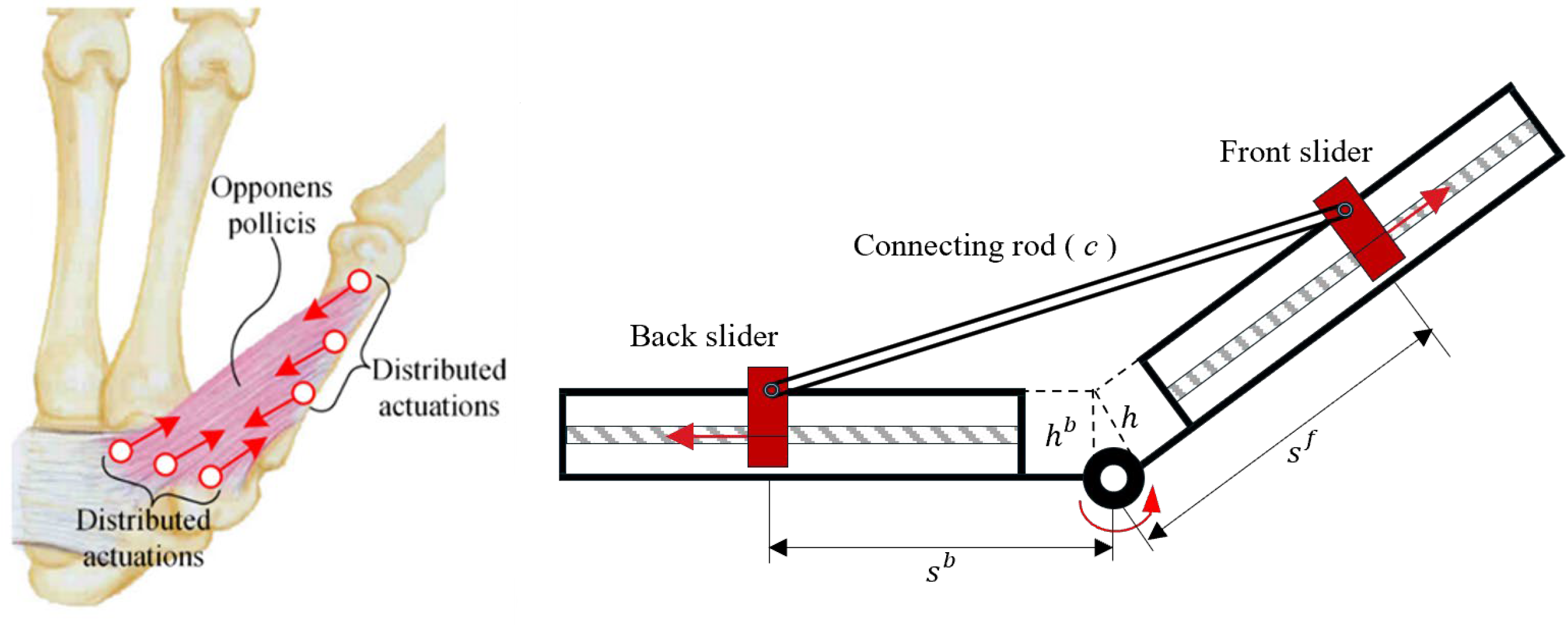
Figure 1. Concept of a single-joint distributed actuation mechanism for mathematical modeling [20].
Mathematics 13 03773 g001
Figure 2. Mathematical modeling and derivation of single-joint DAM.
Mathematics 13 03773 g002
Figure 3. Diagram of DAM-based 3-DOF manipulator.
Mathematics 13 03773 g003
Figure 4. Contour plot of the single joint speed according to the hinge offset and connecting rod.
Mathematics 13 03773 g004
Figure 5. Motor decision according to link’s ratio. (a) Determining suitable motor size based on increased link length. (b) Increase in motor power within the linear performance curve of a DC motor due to motor size scaling.
Mathematics 13 03773 g005
Figure 6. Flowchart of the optimization framework.
Mathematics 13 03773 g006
Figure 7. Optimization results at the end-effector position (xe, ye) = (−100 mm, 150 mm). (a) Optimization history with d = [0, 1]T and |Pe| = 0. (b) Pareto frontier of end-effector velocity and force.
Mathematics 13 03773 g007
Table 1. Design parameters of DAM.
Design
Variables
Joint 1Joint 2Joint 3
Lower
Bound
Upper
Bound
Lower
Bound
Upper
Bound
Lower
Bound
Upper
Bound
θ 1   [ ° ] θ 1 ( l ) θ 1 ( u ) 20.090.020.090.0
s i   [ mm ] 37.077.037.077.037.077.0
s i b   [ mm ] 37.077.037.077.037.077.0
s ˙ i   [ mm ] −14.014.0−14.014.0−14.014.0
s ˙ i b   [ mm ] −14.014.0−14.014.0−14.014.0
h i   [ mm ] 10.020.010.020.010.020.0
h i b   [ mm ] 10.020.010.020.010.020.0
c i   [ mm ] 77.0154.077.0154.077.0154.0
l i   [ mm ] 114.0200.087.0129.080.0129.0
Design
constants
Joint 1Joint 2Joint 3
M8
F m a x   [ N ] F max a d v
s ˙ m a x [mm/s] s ˙ m a x a d v
Table 2. Optimization results of velocity and payload at p1, p2, and p3.
DAM (Init)DAM (Adv)Difference
p1Max |ve| [mm/s]67.63159.0657.48%
Max |F| [N]183040.00%
p2Max |ve| [mm/s]87.42191.5554.36%
Max |F| [N]162638.46%
p3Max |ve| [mm/s]144.02269.4146.54%
Max |F| [N]142441.66%
Table 3. Optimal solution of parameters at p2.
InitialOptimal SolutionDifference
h 1 [mm]15.52022.5%
h 2 [mm]15.52022.5%
h 3 [mm]15.52022.5%
c 1 [mm]8010020%
c 2 [mm]8010020%
c 3 [mm]8010020%
l 1 [mm]11414822.97%
l 2 [mm]11412911.62%
l 3 [mm]12780−37%
Disclaimer/Publisher’s Note: The statements, opinions and data contained in all publications are solely those of the individual author(s) and contributor(s) and not of MDPI and/or the editor(s). MDPI and/or the editor(s) disclaim responsibility for any injury to people or property resulting from any ideas, methods, instructions or products referred to in the content.