Article

Joint Wavelet and Sine Transforms for Performance Enhancement of OFDM Communication Systems

1
Department of Telecommunication Engineering, College of Engineering at Ahlia University, Manama 10878, Bahrain
2
Department of Communications and Computer Engineering, The Higher Institute of Engineering at Al-Shorouk City, Cairo 11837, Egypt
3
Department of Electrical and Electronics Engineering, College of Engineering and Computer Science, Jazan University, Jizan 45142, Saudi Arabia
*
Authors to whom correspondence should be addressed.
Mathematics 2025, 13(20), 3258; https://doi.org/10.3390/math13203258 (registering DOI)
Submission received: 9 September 2025 / Revised: 8 October 2025 / Accepted: 10 October 2025 / Published: 11 October 2025
(This article belongs to the Special Issue Computational Intelligence in Communication Networks)

Abstract

This paper presents a modified Orthogonal Frequency Division Multiplexing (OFDM) system that combines Discrete Wavelet Transform (DWT) with Discrete Sine Transform (DST) to enhance data rate capacity over traditional Discrete Fourier Transform (DFT)-based OFDM systems. By applying Inverse Discrete Wavelet Transform (IDWT) to the modulated Binary Phase Shift Keying (BPSK) bits, the constellation diagram reveals that half of the time-domain samples after single-level Haar IDWT are zeros, while the other half are real. The proposed system utilizes these 0.5 N zero values, modulating them with the DST (IDST) and assigning them as the imaginary part of the signal. Performance comparisons demonstrate that the Bit-Error-Rate (BER) of this hybrid DWT-DST configuration lies between that of BPSK and Quadrature Phase Shift Keying (QPSK) in a DWT-based system, while also achieving data rate improvement of 0.5 N . Additionally, simulation results indicate that the proposed approach demonstrates stable performance even in the presence of estimation errors, with less than 3.4% BER degradation for moderate errors, and consistently better robustness than QPSK-based systems while offering improved data rate efficiency over BPSK. This novel configuration highlights the potential for more efficient and reliable data transmission in OFDM systems, making it a promising alternative to conventional DWT or DFT-based methods.
Keywords:
DWT; DST; BPSK; QPSK; OFDM; CFO; BER
MSC:
94A05; 94A12

1. Introduction

In wireless communication systems like Wi-Fi, 4G, and 5G, OFDM is essential due to its ability to maximize spectrum efficiency and resist multipath interference [1,2,3,4,5]. OFDM works by dividing the available bandwidth into many orthogonal subcarriers, each transmitting a separate portion of the data, which significantly reduces Inter-Symbol Interference (ISI) caused by signal reflections [6]. Unlike Frequency Division Multiplexing (FDM), OFDM enables subcarrier frequencies to overlap without interference, greatly improving spectral utilization [7]. This technology’s ability to handle frequency-selective fading makes it ideal for broadband applications. Each subcarrier in OFDM is independently modulated, making the system more resilient to channel issues as data is distributed over numerous subcarriers. The use of a cyclic prefix (CP), a repeated segment of the signal, helps mitigate multipath delay spread, further enhancing resistance to ISI [8]. Particularly useful in 4G and 5G environments, OFDM supports high data rates and vast connectivity. When paired with Multiple-Input–Multiple-Output (MIMO) technology, which enables spatial multiplexing, OFDM’s performance further improves [9]. Additionally, OFDM’s frequency-domain equalization is much simpler than time-domain equalization, reducing receiver complexity significantly [10,11].
The adoption of OFDM in contemporary wireless systems comes with a mixture of benefits and limitations that shape its effectiveness [12,13,14]. A primary advantage of OFDM is its efficient use of the available spectrum, achieved by partitioning the bandwidth into multiple orthogonal subcarriers, which significantly suppress ISI and facilitate high data rates [15,16]. This feature is particularly valuable in multipath-rich environments, making OFDM ideal for urban communication networks [17]. Nevertheless, OFDM is not without its drawbacks. It is sensitive to issues such as frequency offsets and phase noise, which can lead to performance degradation and necessitate sophisticated synchronization mechanisms [18,19]. Additionally, OFDM signals are characterized by a high Peak-to-Average Power Ratio (PAPR), presenting challenges in power amplification that can result in signal distortion [20,21]. Despite these hurdles, OFDM’s strengths in countering frequency-selective fading and its ability to integrate with advanced techniques like MIMO contribute to its continued prominence in next-generation wireless technologies [22]. By acknowledging and addressing its limitations, engineers can effectively harness OFDM’s potential for improved communication performance in diverse settings [23].
The use of the DST in OFDM systems offers advantages in terms of reducing PAPR [24], which is essential for efficient power use and minimizing interference in wireless and optical communications [25]. DST-OFDM systems transform the input data using DST, which maps data symbols onto sine waveforms. This approach is particularly beneficial in optical communication because it supports intensity modulation and direct detection (IM/DD) systems that operate effectively with non-negative signals [26], as in Visible Light Communications (VLCs) and other optical channels [27,28]. DST in OFDM setups is further enhanced through various types of sine transforms and localized or interleaved mapping strategies. For example, combining DST with interleaved or localized OFDMA mapping (DST-IOFDMA or DST-LOFDMA) enables a more robust handling of compression in multimedia transmission while maintaining a low Signal-to-Noise Ratio (SNR) requirement. This is especially beneficial when applied with low power consumption techniques such as QPSK modulation over specific channel models like SUI3, supporting high transmission fidelity and bandwidth efficiency [29]. Studies have also explored DST in secure image transmissions over LTE and other wireless systems, where IDST is part of the orthogonal transform stages that improve security and reliability in compressed image transmissions by reducing vulnerability to noise and distortion [30]. Furthermore, DST-based systems have shown better performance than DFT-based ones in specific scenarios, highlighting their adaptability for future networks like 5G that demand both efficiency and flexibility [30].
The OFDM can be implemented using DWT or DST instead of DWT. DWT is a mathematical technique used to transform a signal into its component wavelets, allowing for better time–frequency analysis. DST uses sine functions, often applied in signal processing for compression and analysis.
The main contributions of the proposed system are summarized in Table 1, highlighting the key features, their advantages, and potential limitations to provide a balanced overview of the system’s performance and design trade-offs.
The rest of the paper is organized as follows: Section 2 presents the proposed OFDM system model based on the integration of DWT and DST, including the dual modulation technique and system architecture. Section 3 discusses the simulation setup, evaluates the BER performance under various conditions, and compares the proposed scheme with conventional DWT- and DST-based OFDM systems. Section 4 concludes the paper by summarizing the main findings. Section 5 outlines possible directions for future work, including extensions to MIMO-OFDM systems, adaptive power allocation strategies, and real-time validation through hardware platforms.

2. Proposed DWT-OFDM System Model

Figure 1 illustrates the structure of an OFDM communication system incorporating the DWT with a Haar wavelet. The process begins with the modulation of randomly generated bits using the IDWT, which includes up-sampling through low-pass and high-pass filters (LPF and HPF). A CP is then appended to the signal before transmission through the channel. The model takes into account channel impairments, such as h , which represents the channel impulse response, ε, the normalized CFO, defined as the ratio of the actual frequency offset to the subcarrier spacing, and z , which denotes the additive noise introduced during transmission. Upon receiving the signal, the CP is removed, followed by CFO correction and equalization. Finally, the DWT is applied, which entails down-sampling via LPF and HPF filters.
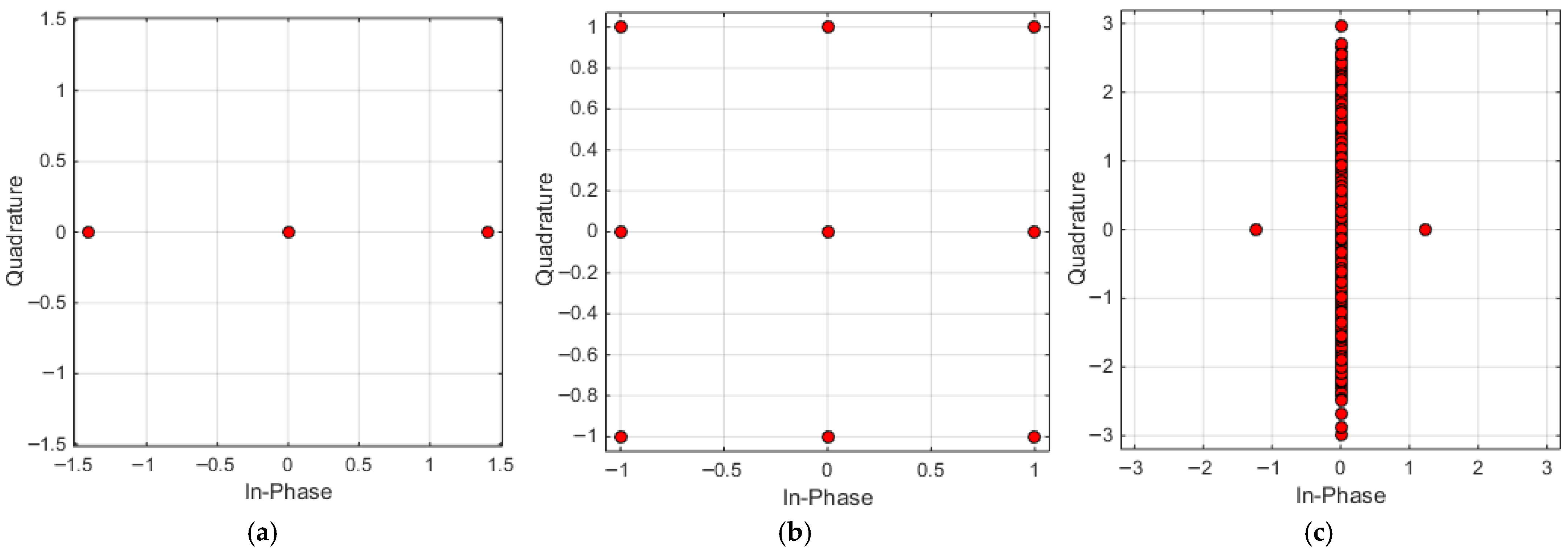
To gain insight into how the proposed OFDM system utilizing DWT operates, we can examine how BPSK symbols are modulated through IDWT. The BPSK is a digital modulation scheme where the phase of the carrier signal is shifted to represent binary data, with two distinct phases for 0 and 1. In Figure 2a, a constellation diagram illustrates BPSK symbols modulated by IDWT using BPSK, while Figure 2b presents the modulation of IDWT bits using QPSK. QPSK is a modulation scheme that uses four phase shifts to encode two bits of data per symbol, improving bandwidth efficiency compared to BPSK. In Figure 2a, the modulated bit sequence includes real values that are both positive and negative, alongside zeros. For a sequence of length N , half of these symbols 0.5 N are zeros. This setup utilizes these 0.5 N zero symbols for additional modulation through IDST. Consequently, the constellation diagram of this arrangement features a line of symbols along the imaginary axis, representing symbols modulated by IDST, as illustrated in Figure 2c.
Figure 3 illustrates the setup of the proposed configuration. First, a sequence of BPSK symbols with a length of N undergoes IDWT modulation, identifying the positions of zeros spanning a length of 0.5 N . Next, a second sequence of BPSK symbols, this time with a length of 0.5 N , is modulated using IDST, aligned along the imaginary axis, and combined with the previous signal, as shown in Figure 2c. A CP is then appended to this composite signal before it is transmitted over a Rayleigh fading channel. Like the standard approach depicted in Figure 1, this model also includes CFO and noise effects. At the receiver, the CP is removed, followed by equalization and CFO correction. A DWT operation is then applied to recover the original N bits. After estimating these N bits, the IDWT is utilized to pinpoint the initial zero locations of length 0.5 N . The imaginary components at these zero positions are extracted and processed using DST to retrieve the remaining 0.5 N transmitted bits.
The transmitted data vectors, before entering the IDWT and IDST blocks and corresponding to the vector, can be represented as
X 1 = X 0 1 X 1 1 X N 2 1 X N 1 1 T
and,
X 2 = X 0 2 X 1 2 X 0.5 N 2 2 X 0.5 N 1 2 T
where # T is the matrix transpose of # , X 1 R N × 1 , and X 2 R 0.5 N × 1 . Next, the IDWT and IDST of each data vector are applied and then summed as follows:
x = w N 1 X 1 + j A S 0.5 N 1 X 2
where w N 1 R N × N is the IDWT matrix, and S 0.5 N 1 R 0.5 N × 0.5 N is the IDST matrix.
The first term w N 1 X 1 is a vector of length N . However, the second term S 0.5 N 1 X 2 results in a vector of length 0.5 N . Since these two vectors have different lengths, they cannot be directly summed. To resolve this, the output of the second term must be expanded from length 0.5 N to length N by inserting zeros at specific positions. This expansion can be represented by a zero-padding matrix A R N × 0.5 N , which maps the 0.5 N -length vector to an N -length vector by inserting zeros in the appropriate places. The IDWT is defined as
w 1 = h t u
The IDWT matrix actually comprises two combined matrices: the up-sampling matrix u R 2 N × N , which is defined as
u = 1 0 0 0 0 0 0 0 0 0 0 0 1 0 0 0 0 0 0 0 0 0 0 0 1 0 0 0 0 0 0 0 0 0 0 0 0 0 0 0 0 0 0 0 0 0 0 0 0 0 0 0 0 0 0 1 0 0 0 0 0 0 0 0 0 0 0 1 0 0 0 0 0 0 0 0 0 0 0 1
and, the LPF and HPF matrices h t R N × 2 N , h t = h o ; h 1 , h 0 , h 1 R N × N , are defined as
h 0 = 1 2 1 1 0 0 0 0 0 0 0 0 1 1 0 0 0 0 0 0 0 0 1 1 0 0 0 0 0 0 0 0 1 1 0 0 0 0 0 0 0 0 0 1 1 0 0 0 0 0 0 0 0 1 1 0 0 0 0 0 0 0 0 1 1 0 0 0 0 0 0 0 0 1
and
h 1 = 1 2         1 1       0       0       0             0       0       0       0       0       1 1       0       0             0       0       0       0       0       0       1 1       0             0       0       0       0       0       0       0       1 1             0       0       0       0       0       0       0       0       0             1 1       0       0       0       0       0       0       0             0       1 1       0       0       0       0       0       0             0       0       1 1       0       0       0       0       0             0       0       0       1
The 0.5 N -points IDST matrix is defined as
S 0.5 N 1 = 2 N + 1 sin π k n N + 1 , k , n = 1,2 , . . , 0.5 N
At this stage, the CP is added, and the signal is transmitted through the channel as follows:
x C P = P C P + x i = x 0 , C P x 1 , C P . . x N 2 , C P x N 1 , C P T
with
P C P + = [ 0 N C P × ( N N C P ) ; I N C P × N C P ] T , I N × N T
In this context, P C P + R N + N C P × N , and x C P R N + N C P × 1 , where N C P resignifies the length of the cyclic prefix. The notation I a × b refers to an identity matrix of dimensions a × b , while 0 a × b represents an a × b matrix populated entirely with zeros. Subsequently, the data is transmitted through a Rayleigh fading channel. The received vector incorporates effects from Rayleigh fading, CFO, and noise, and is expressed as
y = ψ   H P C P +   x + z
In this context, y C ( N + N C P ) × 1 denotes the received vector following the removal of the CP, while x C N + N C P × 1 represents the complex Additive White Gaussian Noise (AWGN) vector, which has a mean of zero. The CFO is represented by a diagonal matrix ψ C N + N C P × N + N C P , defined as follows:
ψ = D i a g 1 , e j 2 π ε N , e j 4 π ε N , , e j 2 π ε N + N C P 2 N , e j 2 π ε N + N C P 1 N
The CFO indicates the ratio of the frequency shift to the defined frequency deviation, which is expressed as follows:
ε = f Δ f
The Impulse Response Matrix (IRM) of the channel H C N + N C P × N + N C P , is defined as
H = h 0 h 1 h L 1 0 0 0 0 0 0 0 h 0 h 1 h L 1 0 0 0 0 0 0 0 h 0 h 1 h L 1 0 0 0 0 0 0 0 h 0 h 1 h L 1 0 0 0 0 0 0 0 0 0 h 0 h 1 h 2 h 3 0 0 0 0 0 0 0 h 0 h 1 h 2 0 0 0 0 0 0 0 0 h 0 h 1 0 0 0 0 0 0 0 0 0 h 0
The channel impulse response is denoted by h w , where w 1 , 2 , , L 1 signifies the number of taps in the Rayleigh fading channel. Upon reception, the CPs were removed, resulting in the following output vector:
y ¯ = P C P y = P C P ψ   H P C P + x + P C P z
In this context, the matrix for CP removal is denoted as P C P R N × N + N C P . Subsequently, a Linear Minimum Mean Square Error Equalizer (LMMSE) is employed to address both the equalization process and the compensation for CFO. The solution matrix corresponding to this equalizer is provided by
γ = Λ H · Λ + R z σ x 2 I N × N 1 Λ H
In this equation Λ = P C P ψ   H P C P + , the expression σ x 2 R z = x . x H R Z = E z . z H delineates the Signal-to-Noise Ratio (SNR), with E # representing the expected value of the enclosed expression. Therefore, the outcome following equalization and CFO compensation can be formulated as
y ~ = x + ϕ
where ϕ = γ P C P z . The direct decoding of the N bits is achieved using the DWT as follows:
X ^ 1 = w N y ~
In this context, w N = d   h r denotes the DWT matrix, which comprises two fundamental components: one for down-conversion and the other functioning as the low-pass and high-pass filters. The matrix used for down-conversion is defined as follows:
d = 0 0 0 0 0 0 1 0 0 0 0 0 0 0 0 0 0 0 0 1 0 0 0 0 0 0 0 0 0 0 0 0 1 0 0 0 0 0 0 0 0 0 0 0 0 1 0 0 0 0 0 0 0 0 0 0 0 0 1 0 0 0 0 0 0 0 0 0 0 0 0 1
The h 0 matrix is defined in Equation (6), and h 2 matrix is given as
h 2 = 1 2 1       1       0       0       0             0       0       0       0       0 1       1       0       0             0       0       0       0       0       0 1       1       0             0       0       0       0       0       0       0 1       1             0       0       0       0       0       0       0       0       0       1       1       0       0       0       0       0       0       0             0 1       1       0       0       0       0       0       0             0       0 1       1       0       0       0       0       0             0       0       0 1
Following the estimation of the initial N -bit data vector, the subsequent step involves recovering the remaining 0.5 N bits. This process starts by identifying the positions of the zeros, which is achieved by reapplying the IDWT, as illustrated in Figure 3. After pinpointing the locations of the zeros, the imaginary component of the equalizer’s output at these specific points is extracted. This extracted imaginary part undergoes a DST operation to reconstruct the remaining 0.5 N -bit data vector.

3. Simulation Results and Analysis

This section undertakes a thorough evaluation and analysis of the proposed OFDM configuration, contrasting its performance with that of traditional systems by scrutinizing key metrics such as BER (i.e., number of bits received incorrectly over the total number of bits sent), SNR improvements, and data transmission capacity. The primary objective is to assess the efficacy of the proposed design under realistic channel conditions, particularly within a Rayleigh fading environment characterized by CFO and noise interference. To facilitate a fair and consistent benchmarking process, specific simulation parameters have been meticulously established. The transform size is designated as 64, signifying the number of subcarriers employed in the modulation scheme, while a CP length of 16 is selected to mitigate inter-symbol interference, particularly in multipath fading situations. The Rayleigh fading channel is modeled using Jakes’ framework, ensuring the creation of a realistic fading environment that accurately reflects the challenges encountered under varying conditions [31]. The SNR is systematically varied from 0 to 21 dB in 3 dB increments, thereby encompassing a broad spectrum of noise scenarios. Furthermore, the normalized CFO is represented by a uniform distribution within the range of ε m a x , + ε m a x , capturing the typical frequency misalignment that occurs between the transmitter and receiver in practical communication scenarios. To enhance the statistical reliability of the results, the simulations are executed over 10 3 iterations, allowing for a comprehensive assessment of performance variations across diverse channel and noise conditions. This extensive setup establishes a robust and statistically sound foundation for comparing the effectiveness of the proposed OFDM configuration in the presence of realistic channel impairments.
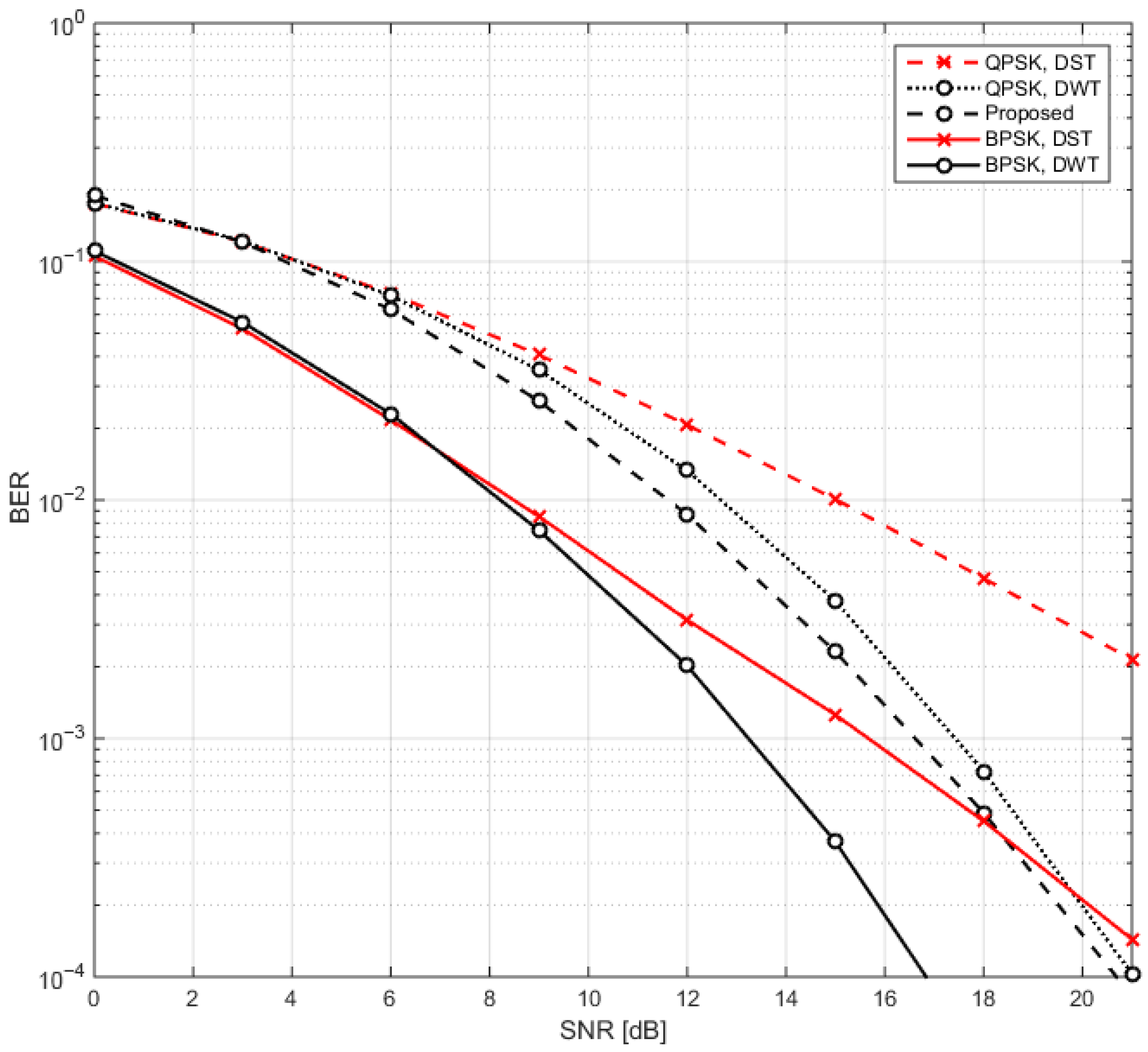
Figure 4 presents a comprehensive analysis of the BER in relation to SNR for the traditional OFDM system utilizing DWT- and DST-based modulation schemes, specifically BPSK and QPSK. This comparative study sheds light on the performance dynamics of each configuration, particularly in terms of their capabilities to balance data transmission rates, error rates, and the requisite SNR levels. Such a setup not only enhances our understanding of the trade-offs involved but also establishes a robust and statistically valid framework for evaluating the effectiveness of the proposed OFDM configuration amidst realistic channel impairments.

3.1. Transmission Capacity

In the BPSK configuration, the system prioritizes reliability and error correction by transmitting N data symbols per time unit. While this approach effectively mitigates errors, it does so at the cost of overall data throughput. On the other hand, the QPSK configuration enhances data transmission by sending 2 N symbols, thereby effectively doubling the data rate compared to BPSK. However, this increased throughput comes with heightened vulnerability to noise and interference, which can compromise signal integrity. The proposed transmission scheme offers a compelling alternative by sending 1.5 N data symbols, thereby positioning itself as a middle ground between the BPSK and QPSK methods. This configuration achieves a balanced data rate while simultaneously improving resilience against disturbances, making it particularly advantageous for applications that necessitate both speed and reliability. Furthermore, the adaptability in transmission capacity inherent in this proposed method enables it to meet diverse user requirements, rendering it an optimal choice for systems that demand a judicious blend of reasonable data rates and robust performance in the face of potential signal degradation.

3.2. BER Performance

At BER = 10 3 , the proposed configuration demonstrates an SNR improvement of around 0.98 dB when compared to a DWT-OFDM system that employs QPSK modulation. This improvement suggests that the new configuration operates with enhanced efficiency, yielding lower error rates for a given SNR compared to the QPSK-based DWT-OFDM system. Despite this advantage, both the proposed configuration and the QPSK system still do not reach the BER performance of a DWT-OFDM system using BPSK modulation. To achieve comparable BER performance, an additional SNR boost ranging from 3.22 dB to 4.2 dB is required, which underscores the higher reliability of BPSK. However, this reliability in BPSK comes with a trade-off: a reduced data transmission rate due to its binary nature. When compared to a DST-OFDM system, the proposed configuration shows a significant SNR gain of approximately 4.56 dB over the QPSK signaling scheme. Moreover, the new configuration only requires an additional 0.91 dB to achieve the BER performance equivalent to that of the BPSK system. This finding highlights the competitive efficiency of the proposed system, as it comes close to achieving reliable data transmission with minimal SNR increases, balancing both performance and robustness.
At BER = 10 4 , the proposed configuration demonstrates significant improvements in SNR, achieving approximately 0.35 dB more than the QPSK configuration within the DWT-OFDM framework. This gain is particularly beneficial for applications demanding minimal error rates, as it indicates the proposed configuration’s enhanced robustness against challenging noise conditions. Nevertheless, both the proposed configuration and QPSK still require additional SNR to match the error rate performance of BPSK when applied within the DST-OFDM context. Specifically, the proposed configuration needs an extra 3.85 dB, while QPSK requires 4.17 dB to reach BPSK’s error resilience. This insight underlines BPSK’s superior stability, even though it operates at a reduced data rate, making it an optimal choice for environments where stringent reliability is critical. In comparison to DST-OFDM, the proposed configuration offers a notable SNR gain of around 0.72 dB, surpassing both BPSK and QPSK in resilience. This performance suggests that the new configuration achieves a valuable balance between data rate and error performance, positioning itself strategically between BPSK and QPSK in terms of both capacity and reliability. With a transmission capacity of 1.5 N , the configuration is suitable for applications that need moderate data rates along with improved error resistance. The observed SNR improvements at lower BER levels further underscore the system’s robustness, especially in cases where intermediate data rates are sufficient but where reliability holds greater importance than peak data throughput. The analysis benefits from uniform power allocation across configurations, ensuring a fair and direct comparison that highlights the proposed configuration’s advantages. This is particularly meaningful in real-world wireless scenarios where power constraints, noise interference, and channel variability significantly influence performance. Altogether, this evaluation establishes that the proposed configuration is a strong alternative to conventional systems, offering a flexible solution adaptable to diverse user needs by balancing data rate and reliability effectively.
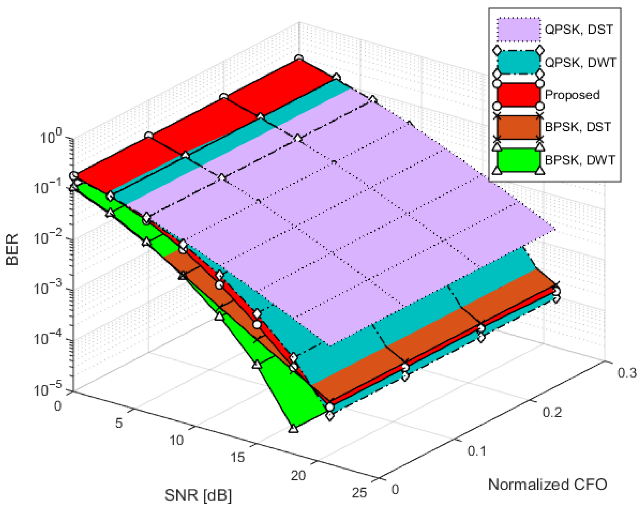
Figure 5 presents the BER versus SNR curves at various values of normalized CFO for multiple modulation schemes, including the proposed one. The plot reveals that in the absence of CFO estimation errors, all schemes demonstrate resilience, as well as the proposed model. This confirms its robustness against CFO distortions, which are particularly problematic in systems with high mobility or oscillator mismatches.
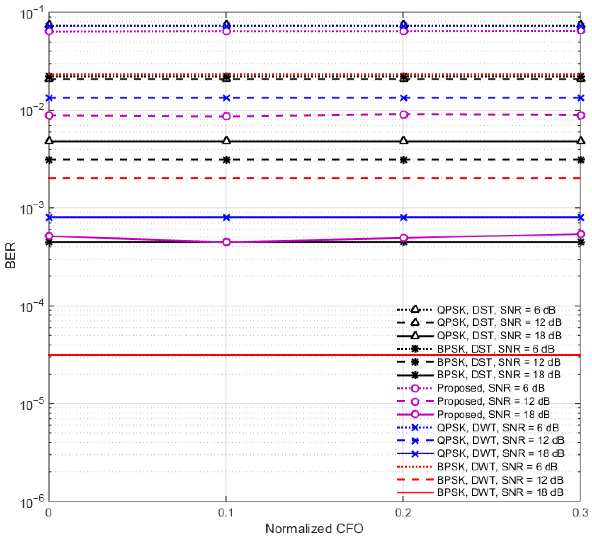
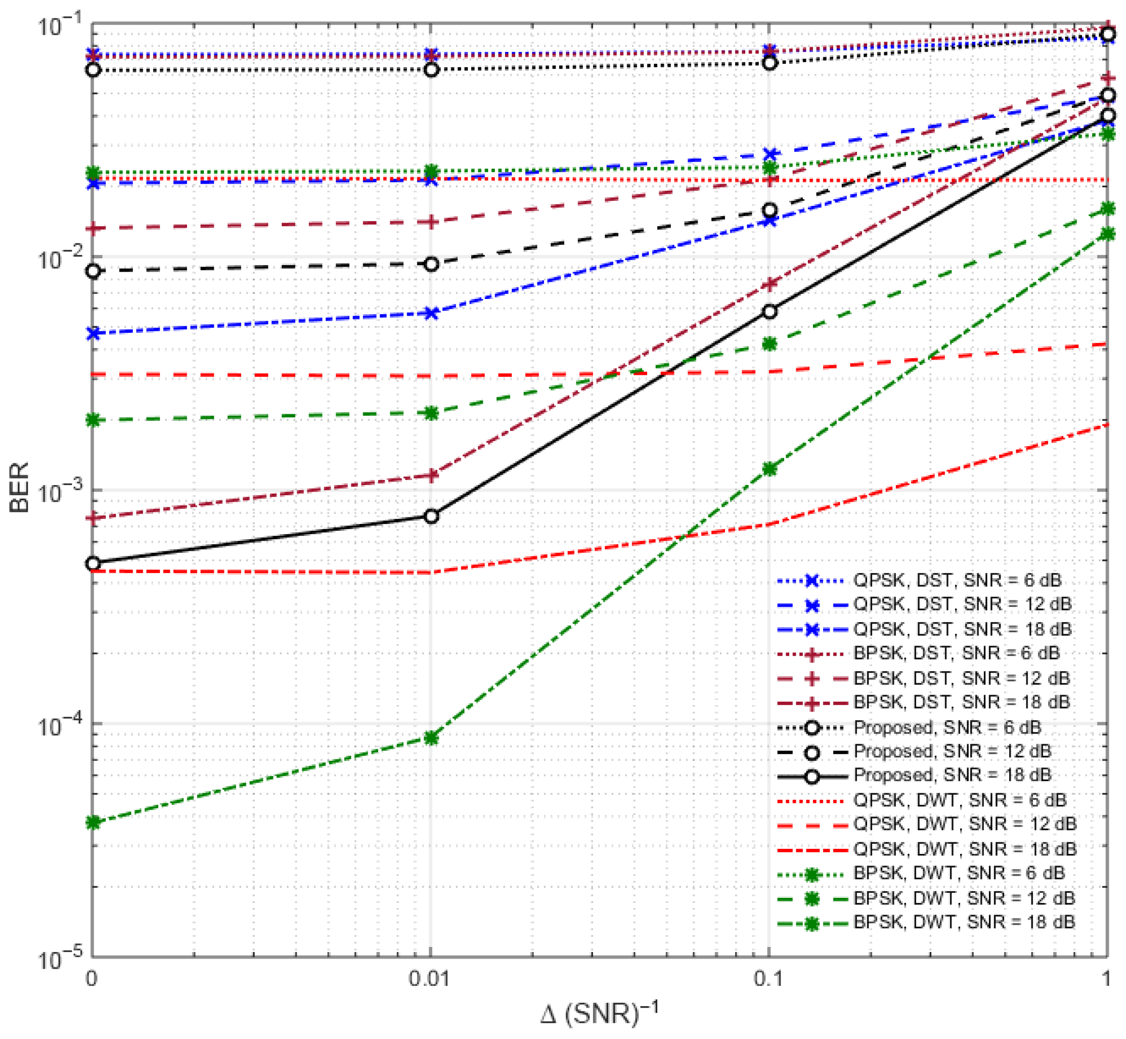
To further clarify the effect of CFO on system performance, Figure 6 provides a three-dimensional side-view plot derived from Figure 5, showing the BER variation as a function of normalized CFO (ε) at fixed SNR levels of 6, 12, and 21 dB. This figure offers deeper insight into the CFO robustness of various OFDM schemes, including the proposed DWT-DST system, and conventional BPSK and QPSK configurations using DWT and DST.
At an SNR of 6 dB, the BER values at ε = 0.1 are 0.07345 for QPSK-DST, 0.02204 for BPSK-DST, 0.06427 for the proposed DWT-DST, 0.07183 for QPSK-DWT, and 0.02309 for BPSK-DWT. At 12 dB, the corresponding BER values improve to 0.02084 (QPSK-DST), 0.003106 (BPSK-DST), 0.008617 (proposed), 0.01332 (QPSK-DWT), and 0.002019 (BPSK-DWT). At 18 dB, the proposed scheme achieves a very low BER of 0.0004458, which is slightly better than QPSK-DWT (0.0008031) and QPSK-DST (0.004806), but slightly worse than BPSK-DWT (3.125 × 10⁻⁵) and BPSK-DST (0.00045).
These results confirm that the proposed system maintains low BER across a wide range of CFO values and SNR conditions, with performance stability comparable to BPSK-based schemes and superior to QPSK variants in most cases. Moreover, the proposed method benefits from a higher data rate (1.5 N ) compared to BPSK-based systems ( N ), representing a favorable trade-off between robustness and throughput. The smooth curves observed in Figure 6 demonstrate that the proposed system does not exhibit sharp performance degradation as CFO increases, making it suitable for deployment in high-mobility or oscillator-impaired environments where CFO is a critical issue.
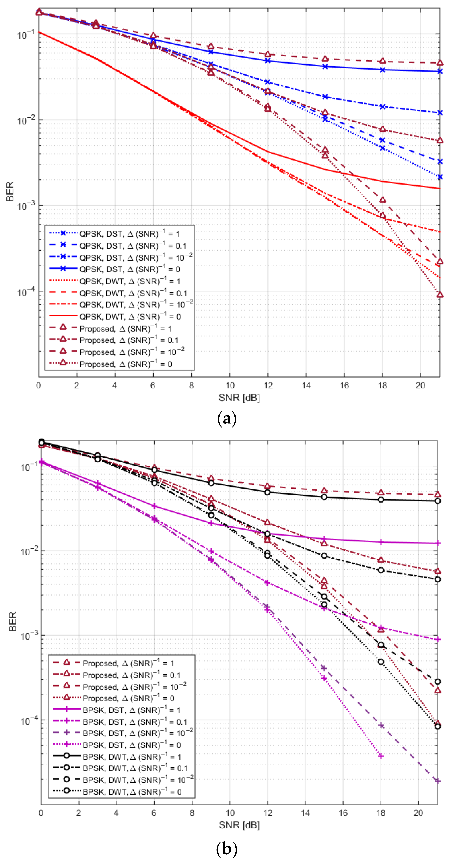
In parallel, Figure 7, Figure 8 and Figure 9 shift focus to the impact of SNR estimation errors, another real-world impairment. Figure 7 focuses on the impact of SNR estimation errors on BER performance across different modulation schemes, including the proposed DWT-DST system. The figure plots BER versus SNR under varying levels of SNR estimation error, simulating real-world inaccuracies in channel state information. As the estimation error increases, the BER performance of all schemes degrades, highlighting the sensitivity of coherent detection to such impairments. However, the proposed system maintains consistently lower BER than QPSK-based configurations across the entire SNR range, demonstrating better robustness against SNR estimation errors.
To illustrate with numerical results at an SNR of 18 dB, the BER for QPSK-DST increases from 0.005744 at Δ ( S N R ) 1 = 0.01 to 0.01427 at 0.1, while QPSK-DWT increases from 0.001159 to 0.007653. In contrast, the proposed DWT-DST scheme shows a more moderate increase, from 0.000775 to 0.005858, under the same conditions. These results confirm that the proposed method demonstrates improved resilience compared to QPSK-based systems.
While BPSK-DWT and BPSK-DST still perform best in absolute BER terms, with BERs of 8.75 × 1 0 5 and 0.0004438 at Δ ( S N R ) 1 = 0.01 , respectively, they offer lower data rates ( N ) compared to the 1.5 N of the proposed scheme, which introduces a trade-off between robustness and throughput. This positions the proposed system as a balanced solution, combining enhanced spectral efficiency with tolerable sensitivity to SNR estimation inaccuracies.
Figure 8a corresponds to the proposed system with QPSK modulation, while Figure 8b shows the performance with BPSK modulation. These plots provide a clearer perspective on the trends observed in Figure 7, by highlighting the impact of modulation type on system behavior. As expected, increasing the SNR leads to a reduction in BER; however, this improvement becomes less pronounced as the SNR estimation error increases, emphasizing the critical role of estimation accuracy. Overall, the proposed system maintains strong performance across both modulation schemes, particularly at moderate to high SNR levels and under reasonable estimation error conditions, demonstrating its robustness against estimation imperfections.
Figure 9 presents a side-view plot of Figure 7, where BER is graphed against SNR estimation error at fixed SNR levels. This figure further quantifies the degradation rate and confirms that, although the proposed system outperforms others across all tested scenarios, its performance still depends on the fidelity of the SNR estimate. Taken together, Figure 5, Figure 6, Figure 7, Figure 8 and Figure 9 validate the resilience of the proposed model to CFO and SNR estimation errors. The comparative analysis shows that it consistently outperforms conventional schemes under both impairments, making it a promising candidate for deployment in realistic, dynamically varying wireless environments.
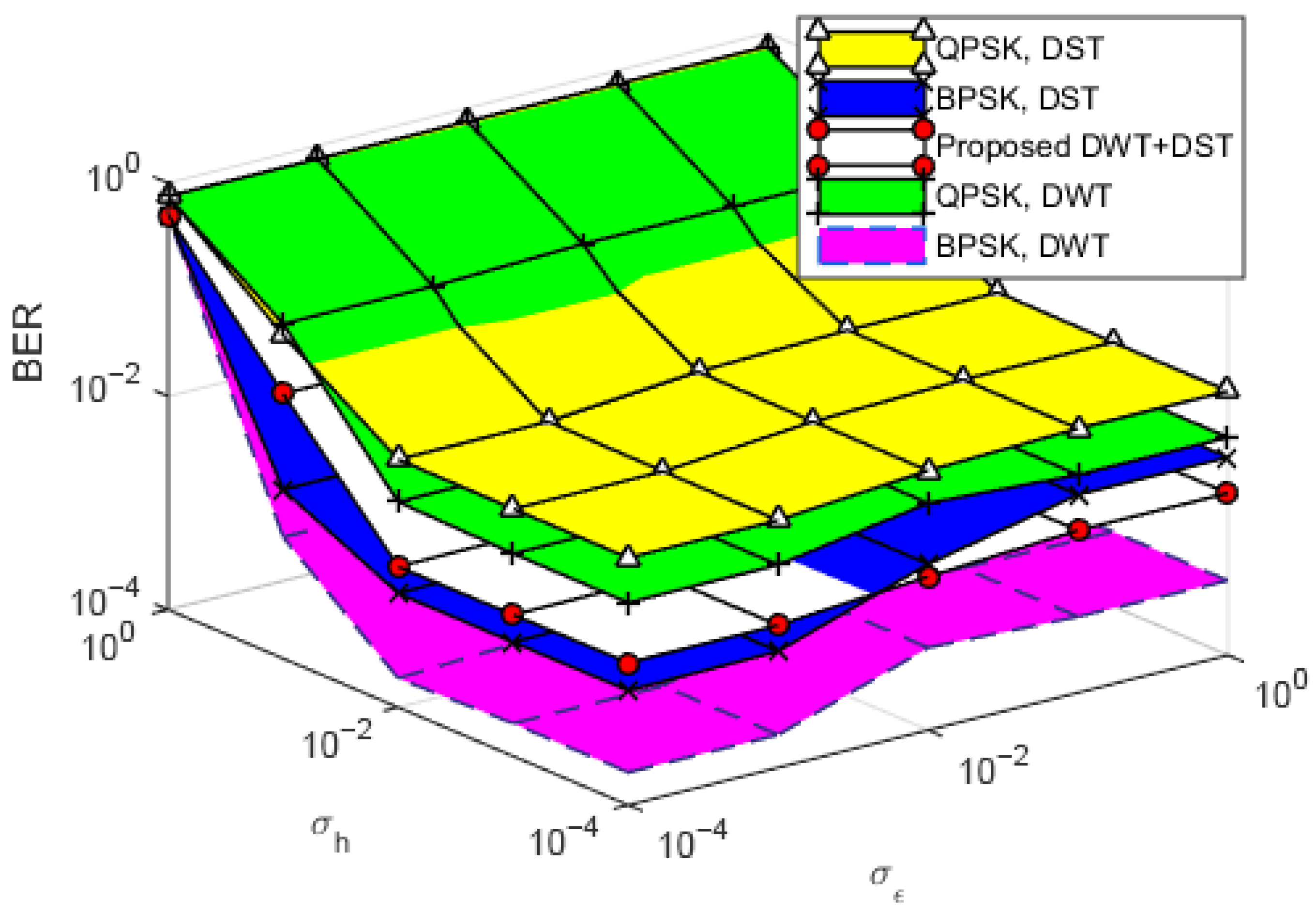
Figure 10 illustrates the BER performance at a SNR of 15 dB, with a specific focus on the impact of channel estimation errors. These errors are quantified through standard deviations σ h representing variations in the channel and σ ε capturing CFO inaccuracies. The findings offer a comparative analysis of the proposed configuration versus traditional schemes, highlighting the proposed method’s robustness against estimation errors in both channel variations and CFO. The data demonstrates that, even under the influence of estimation errors, the proposed algorithm maintains a low BER, underscoring its effectiveness in accurately tracking and correcting these inaccuracies. This robust performance suggests that the proposed configuration is capable of sustaining reliable communication, even in dynamic environments where channel conditions and CFOs are unstable. Such resilience is valuable for practical applications, as real-world communication systems often experience fluctuating conditions that can degrade signal quality. Moreover, the figure emphasizes the adaptability of the proposed scheme, indicating that it can offer a distinct advantage over conventional approaches, especially in scenarios where channel information is imperfect. This adaptability could translate to significant improvements in communication reliability, making the proposed scheme highly relevant for complex and variable communication environments.
To assess the robustness of the proposed DWT-DST-based OFDM system under realistic channel conditions, we evaluated its BER performance in the presence of both channel estimation error ( σ h ) and CFO estimation error ( σ ε ). Table 2 presents a comparative analysis of BER degradation across different modulation schemes, over an estimation error range of σ ε ,   σ h = 10 4 to σ ε , σ h = 10 1 .
For the proposed system, the BER increases from 0.00216 to 0.03571, corresponding to an absolute degradation of 3.36% over the full BER range (0–1). This is estimated using:
Δ B E R 1 = 0.0358 0.00211 1 × 100 % = 3.37 %
Table 2 summarizes the BER degradation percentages of various modulation schemes under increasing channel and CFO estimation errors. As shown, the proposed DWT-DST hybrid system maintains a moderate BER degradation of 3.36%, indicating strong resilience to estimation inaccuracies. In contrast, QPSK-based systems suffer larger degradations, with DWT-QPSK reaching 14.46% and DST-QPSK 9.70%, reflecting their lower robustness under error-prone conditions.
On the other hand, BPSK-based systems exhibit minimal degradation, with DWT-BPSK at 0.19% and DST-BPSK at 0.82%, highlighting their error resilience. However, these systems only modulate N bits, while the proposed system modulates 1.5 N bits. Therefore, while the BER of the proposed system is slightly higher than BPSK, it provides a significant data rate improvement, positioning it as a balanced solution between high reliability (as in BPSK) and high throughput (as in QPSK).

3.3. Accuracy Calculation

Now, the zero-position detection accuracy calculation is presented. In the proposed system, detecting the zero positions in the IDWT output at the receiver is essential because these positions carry additional data via IDST modulation. To evaluate detection accuracy, we compare the detected zero positions with the actual zero positions known from the transmitter.
Since the focus is on identifying zero positions correctly, we define True Positives (TP) as the number of zero positions correctly detected, False Positives (FP) as non-zero positions incorrectly detected as zero, and False Negatives (FN) as zero positions missed by the detector.
Unlike typical binary classification problems, True Negatives (TN), non-zero positions correctly identified as non-zero, are not explicitly considered in the accuracy calculation because the primary concern is the correct identification of zeros for data modulation. Therefore, the detection accuracy is calculated as
A c c u r a c y = T P T P + F P + F N
This accuracy measure focuses on the correct detection of zero positions relative to all positions classified as zero or missed, providing a meaningful metric for system performance.
Figure 11 shows the relationship between zero detection accuracy and SNR in the proposed hybrid DWT-DST OFDM system. The detection accuracy improves significantly as the SNR increases, starting from approximately 60.2% at 0 dB and reaching almost perfect accuracy (100%) at 21 dB.

3.4. Transmitted Power

This trend is expected, as higher SNR values reduce the impact of noise on the received signal, making the zero positions more distinguishable during the inverse wavelet transform process at the receiver. At low SNR values (e.g., 0–6 dB), the detection suffers due to noise masking true zeros or introducing spurious near-zero values, leading to both false positives and false negatives. However, as the SNR crosses 12 dB, the detection accuracy exceeds 94%, indicating the robustness of the zero-position detection mechanism under moderate to high SNR conditions. These results validate the feasibility of using zero positions for secondary modulation (via IDST), particularly in practical scenarios where SNR is within a reasonable operational range.
To fairly compare different transmission schemes, all systems must operate under the same transmitted power, which is ensured in our simulations. For standard modulation, BPSK uses bit amplitudes of ±1 V, while QPSK uses ±1/√2 V to maintain equal power levels. After modulation, signals are passed through IDWT or IDST.
The transmitted power can be calculated using
P o w e r = x · x H
where x is the modulated signal. For both BPSK and QPSK, this value equals N , confirming equal output power for both.
In the proposed model, we also maintain power consistency by generating two sequences: one of length N (amplitude ±1/√1.333) and another of length 0.5 N (amplitude ±1/√2), both BPSK-modulated. These are processed using IDWT and IDST, respectively, and then combined in the real and imaginary parts.
The total signal power before adding the cyclic prefix remains constant as depicted in Equation (23). This confirms that the proposed system transmits at the same power level as conventional BPSK/QPSK schemes, ensuring a fair BER comparison.

4. Conclusions

In this research, a refined OFDM configuration was presented, integrating DWT techniques, and further optimized through the addition of the DST. This innovative approach was designed to enhance data throughput and to improve system robustness against various potential impairments. Through the implementation of this model, issues related to noise, channel fading, and CFO were effectively mitigated, leading to a notable increase in data transmission capacity from N bits to approximately 1.5 N bits.
Although a slight increase in BER was observed when compared to BPSK, the modified system consistently outperformed QPSK systems that employ conventional DWT-OFDM methods. This improvement was demonstrated by substantial SNR gains: specifically, an enhancement of 0.98 dB at a BER of 10−3 and 0.35 dB at 10−4 was achieved. These gains reflect the robustness of the proposed configuration, making it suitable for applications demanding low BER performance.
Moreover, the model was shown to maintain effective operation even under channel estimation inaccuracies, demonstrating its adaptability to real-world scenarios where channel conditions are variable and CFO effects are present. This adaptability is considered essential for wireless communication systems, as it ensures consistent performance across dynamic and unpredictable environments.
In conclusion, the proposed configuration is identified as a versatile and resilient alternative to conventional QPSK and BPSK systems, capable of balancing intermediate data rates with enhanced error resilience. It is regarded as a strong candidate for emerging 6G wireless applications, offering both reliability and adaptability in challenging channel conditions.

5. Future Work

The promising results of the proposed DWT-DST hybrid OFDM configuration open several avenues for future research. First, extending the system to MIMO-OFDM frameworks can further exploit spatial diversity and multiplexing gains, thereby enhancing throughput and reliability in high-mobility environments. Additionally, adaptive power allocation and modulation strategies could be integrated to dynamically balance the trade-off between data rate and error performance, enabling the system to adjust to varying channel conditions in real time.
Another important direction is the hardware implementation and validation of the proposed model using software-defined radio (SDR) platforms or FPGA-based prototypes, which will allow assessment of its feasibility under practical constraints such as latency, computational complexity, and power consumption. Furthermore, exploring the system’s performance in heterogeneous networks, such as visible light communication (VLC), underwater acoustic channels, and beyond-5G/6G scenarios, could highlight its adaptability across diverse applications.
Finally, incorporating advanced techniques such as machine learning-based equalizers, channel estimation algorithms, and PAPR reduction schemes may further enhance robustness and efficiency. These future explorations will help establish the proposed system as a strong candidate for next-generation wireless communication standards.

Author Contributions

Conceptualization, K.R., I.A. and E.S.H.; Methodology, K.R., I.A. and E.S.H.; Software, K.R., I.A. and E.S.H.; Validation, K.R. and E.S.H.; Formal analysis, K.R. and E.S.H.; Investigation, K.R. and E.S.H.; Resources, K.R., I.A. and E.S.H.; Data curation, K.R. and E.S.H.; Writing—original draft, K.R., I.A. and E.S.H.; Writing—review and editing, K.R., I.A. and E.S.H.; Visualization, K.R. and E.S.H.; Supervision, I.A. and E.S.H.; Project administration, E.S.H.; Funding acquisition, I.A. All authors equally contributed. All authors have read and agreed to the published version of the manuscript.

Funding

This research work was funded by the Deanship of Graduate Studies and Scientific Research, Jazan University, Saudi Arabia, through Project number: JU- 202504344 -DGSSR- RP -2025.

Data Availability Statement

The original contributions presented in this study are included in the article. Further inquiries can be directed to the corresponding authors.

Acknowledgments

The authors gratefully acknowledge the funding of the Deanship of Graduate Studies and Scientific Research, Jazan University, Saudi Arabia, through Project number: JU- 202504344 -DGSSR- RP -2025.

Conflicts of Interest

The authors declare no conflicts of interest.

Abbreviations

The following abbreviations are used in this manuscript:
OFDMOrthogonal Frequency Division Multiplexing
DWTDiscrete Wavelet Transform
DFTDiscrete Fourier Transform
DSTDiscrete Sine Transform
BERBit-Error-Rate
BPSKBinary Phase Shift Keying
QPSKQuadrature Phase Shift Keying
FDMFrequency Division Multiplexing
CPCyclic Prefix
MIMOMultiple-Input–Multiple-Output
PAPRPeak-to-Average Power Ratio
LPFLow-Pass Filter
HPFHigh-Pass Filter
CFOCarrier Frequency Offset
SNRSignal-to-Noise Ratio
AWGNAdditive White Gaussian Noise
IDSTInverse Discrete Sine Transform
IDWTInverse Discrete Wavelet Transform
IM/DDIntensity Modulation/Direct Detection
VLCVisible Light Communication

References

  1. Hassan, E.S. Multi-Carrier Communication Systems with Examples in MATLAB®: A New Perspective; CRC Press: Boca Raton, FL, USA; Taylor & Francis: Oxfordshire, UK, 2019; Volume 47, pp. 26–35. ISBN 9781498735322. [Google Scholar]
  2. Yılmaz, G.; Yılmaz, A.Ö. Quasi-Newton FDE in One-bit Pseudo-Randomly Quantized Massive MIMO-OFDM Systems. IEEE Commun. Lett. 2024, 28, 917–921. [Google Scholar] [CrossRef]
  3. Ramadan, K.; Hassan, E.S. Linear WDE for Performance Enhancement of MIMO-OFDM System in the Presence of Co-CFO. Def. Technol. J. 2025, 51, 51–66. [Google Scholar] [CrossRef]
  4. Arabian, F.; Shoushtari, M. A Comparative Study of Waveforms Across Mobile Cellular Generations: From 0G to 6G and Beyond. Telecom 2025, 6, 67. [Google Scholar] [CrossRef]
  5. Lian, D.; Gao, Y.; Lian, J.; Li, Y. Joint DFT and Spacetime Coding for MU-OFDM in Power-Constrained Optical Wireless Communication Systems. Photonics 2025, 12, 11. [Google Scholar] [CrossRef]
  6. Cao, Z.; Tureli, U.; Yao, Y. Low-complexity orthogonal spectral signal construction for generalized OFDMA uplink with frequency synchronization errors. IEEE Trans. Veh. Technol. 2007, 56, 1143–1154. [Google Scholar] [CrossRef]
  7. Zhang, C.; Baharudin, M.A.B.; Guo, T.; Wang, J.; Jia, Z. A Survey on the Latest Developments of OFDM Schemes for Optimizing the Capacity and Reliability of Visible Light Communication (VLC) Systems. KSII Trans. Internet Inf. Syst. 2025, 19, 1625. [Google Scholar] [CrossRef]
  8. Wan, Y.; Hu, Z.; Liu, A.; Du, R.; Han, T.X.; Quek, T.Q.S. OFDM-Based Multiband Sensing For ISAC: Resolution Limit, Algorithm Design, and Open Issues. IEEE Veh. Technol. Mag. 2024, 19, 51–59. [Google Scholar] [CrossRef]
  9. Yeh, H.-G. Architectures for MIMO-OFDM Systems in Frequency-Selective Mobile Fading Channels. IEEE Trans. 2015, 62, 1189–1193. [Google Scholar] [CrossRef]
  10. Li, P.; Pan, W.; Zou, X.; Yan, L. Low-Complexity Adaptive Frequency-Domain Nonlinear Equalization for Analog RoF Mobile Fronthaul Using FFT/IFFT-Assisted Channel Aggregation. J. Light. Technol. 2022, 40, 1072–1082. [Google Scholar] [CrossRef]
  11. Kansal, K.; Berra, S.; Mounir, M.; Miglani, R.; Dinis, R.; Rabie, K. Performance Analysis of Massive MIMO-OFDM System Incorporated with Various Transforms for Image Communication in 5G Systems. Electronics 2022, 11, 621. [Google Scholar] [CrossRef]
  12. Ding, Y.; Deng, H.; Xie, Y.; Wang, H.; Sun, S. Time-Varying Channel Estimation Based on Distributed Compressed Sensing for OFDM Systems. Sensors 2024, 24, 3581. [Google Scholar] [CrossRef]
  13. Lalitha, H.; Kumar, N. Carrier frequency synchronization for WLAN systems based on MIMO-OFDM-IM. EURASIP J. Wirel. Commun. Netw. 2024, 2024, 77. [Google Scholar] [CrossRef]
  14. Sreeraj, S.J.; Lakshman, B.; Ganti, R.; Nirmalathas, A.; Koilpillai, R.D.; Venkitesh, D. Optical Upconversion of OFDM Signals for Next Generation Fronthauling Using Frequency Doubling and Quadrupling. IEEE Access 2024, 12, 39300–39312. [Google Scholar] [CrossRef]
  15. Mohammed, M. Theoretical Analysis and Simulation of IM/DD Optical OFDM Systems; McMaster Universit: Hamilton, ON, Canada, 2011; Available online: http://www.academia.edu/19322099 (accessed on 25 August 2025).
  16. Wen, M.; Li, J.; Cheng, X.; Cheng, X. ICI Cancellation Techniques Based on Data Repetition for OFDM Systems. In Radio Access Network Slicing and Virtualization for 5G Vertical Industries; John Wiley & Sons, Ltd.: Hoboken, NJ, USA, 2021; pp. 1–24. [Google Scholar] [CrossRef]
  17. Farhang-Boroujeny, B. Ofdm versus filter bank multicarrier. IEEE Signal Process. Mag. 2011, 28, 92–112. [Google Scholar] [CrossRef]
  18. Liu, X.; Lu, H.; He, Y.; Wu, F.; Zhang, C.; Wang, X. Analysis on the Effect of Phase Noise on the Performance of Satellite Communication and Measurement System. Symmetry 2023, 15, 2053. [Google Scholar] [CrossRef]
  19. Zhu, C.; He, P.; Wu, S.; Wang, G. An Integrated Orthogonal Frequency-Division Multiplexing Chirp Waveform Processing Method for Joint Radar and Communication Based on Low-Density Parity-Check Coding and Channel Estimation. Electronics 2024, 13, 334. [Google Scholar] [CrossRef]
  20. Rizwana, A.; Srivastava, A. PAPR Reduction of OFDM Signal Through DFT Precoding and GMSK Pulse Shaping in Indoor VLC. IEEE Access 2020, 8, 122092–122103. [Google Scholar] [CrossRef]
  21. Cinemre, I.; Hacioglu, G.; Mahmoodi, T. QCTP: A Novel Pre-Coding Approach for PAPR Reduction in IM/DD Systems. IEEE Access 2024, 12, 115588–115596. [Google Scholar] [CrossRef]
  22. Bouhlel, A.; Sakly, A.; Mansouri, N. Performance Comparison of DWT Based MIMO OFDM and FFT Based MIMO OFDM. Procedia Comput. Sci. 2015, 73, 266–273. [Google Scholar] [CrossRef]
  23. Dang, S.; Zhou, J.; Shihada, B.; Alouini, M. Toward Spectral and Energy Efficient 5G Networks Using Relayed OFDM with Index Modulation. Front. Commun. Netw. 2021, 2, 635295. [Google Scholar] [CrossRef]
  24. Trivedi, V.K.; Ramadan, K.; Kumar, P.; Dessouky, M.I.; El-Samie, F.E.A. Trigonometric transforms and precoding strategies for OFDM-based uplink hybrid multi-carrier nonorthogonal multiple access. Trans. Emerg. Telecommun. Technol. 2019, 30, e3694. [Google Scholar] [CrossRef]
  25. Cinemre, I.; Hacioglu, G. A DCT/DST Based Fast OFDM Method in IM/DD Systems. IEEE Commun. Lett. 2021, 25, 3013–3016. [Google Scholar] [CrossRef]
  26. Dissanayake, S.D.; Armstrong, J. Comparison of ACO-OFDM, DCO-OFDM and ADO-OFDM in IM/DD Systems. J. Light. Technol. 2013, 31, 1063–1072. [Google Scholar] [CrossRef]
  27. Bhadoria, M.P.; Pandey, G.; Dixit, A. Performance evaluation of visible light communication for DCO and ACO optical OFDM techniques. In Proceedings of the 2019 National Conference on Communications (NCC), Bangalore, India, 20–23 February 2019. [Google Scholar]
  28. Androw, S.; Derd, H. Enhancing the performance of optical VLC system based on asymmetric symmetric subcarriers OFDM. Int. J. Commun. Syst. 2020, 33, e4226. [Google Scholar]
  29. Vappangi, S.; Mani, V.V. A Power efficient DST-based multicarrier and multiple access systems for VLC. In Proceedings of the 2018 IEEE International Conference on Advanced Networks and Telecommunications Systems (ANTS), Indore, India, 16–19 December 2018. [Google Scholar]
  30. Baig, I.; ul Hasan, N.; Zghaibeh, M.; Khan, I.U.; Saand, A.S. A DST precoding based uplink NOMA scheme for PAPR reduction in 5G wireless network. In Proceedings of the 2017 7th International Conference on Modeling, Simulation, and Applied Optimization (ICMSAO), Sharjah, United Arab Emirates, 4–6 April 2017. [Google Scholar]
  31. Dent, P.; Bottomley, G.E.; Croft, T. Jakes Fading Model Revisited. Electron. Lett. 1993, 29, 1162–1163. [Google Scholar] [CrossRef]
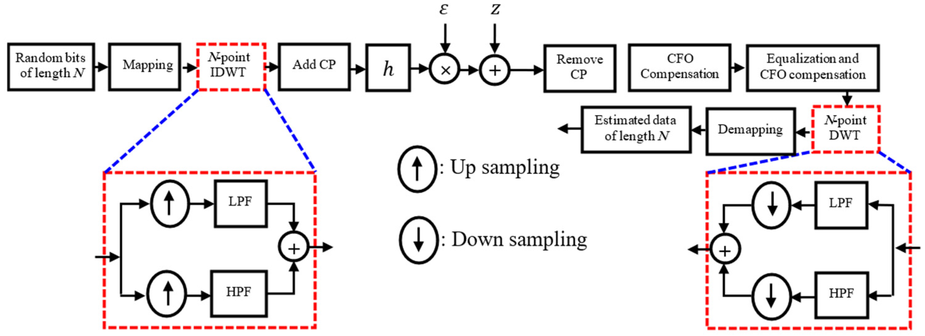
Figure 1. The OFDM structure based on DWT.
Mathematics 13 03258 g001
Figure 2. Constellation diagram of modulated IDWT in the case of (a) BPSK (b) QPSK (c) Proposed.
Mathematics 13 03258 g002
Figure 3. The proposed DWT-OFDM structure based on DST.
Mathematics 13 03258 g003
Figure 4. BER vs. SNR of different systems.
Mathematics 13 03258 g004
Figure 5. BER versus SNR for different values of normalized CFO across multiple systems, including the proposed model.
Mathematics 13 03258 g005
Figure 6. BER as a function of normalized CFO at fixed SNR levels (6, 12, and 18 dB).
Mathematics 13 03258 g006
Figure 7. BER versus SNR performance under varying SNR estimation errors for different schemes, including the proposed method.
Mathematics 13 03258 g007
Figure 8. BER vs. SNR for the proposed scheme with (a) QPSK modulation (b) BPSK modulation at fixed values of SNR estimation errors.
Mathematics 13 03258 g008
Figure 9. BER vs. SNR estimation error at several fixed SNR values.
Mathematics 13 03258 g009
Figure 10. BER in the case of estimation errors of different systems.
Mathematics 13 03258 g010
Figure 11. Zero detection accuracy vs. SNR for the proposed DWT-DST-based OFDM system.
Mathematics 13 03258 g011
Table 1. Summary of Advantages and Potential Limitations of the Proposed System.
FeatureAdvantagesPotential Limitations
Use of DWT instead of DFTImproved spectral efficiency and time–frequency localization; better resilience to multipathIncreased computational complexity in some implementations
Dual Modulation via IDWT and IDST Utilizes   unused   0.5 N zero elements to transmit additional data (imaginary part), increasing throughput by 50%Requires precise synchronization between real and imaginary paths; implementation complexity
Power EfficiencyMaintains similar power efficiency as traditional OFDM systemsNo specific gain in power efficiency, equivalent to conventional methods
BER PerformanceBER lies between BPSK and QPSK, offering a middle ground between robustness and data rateNot as robust as pure BPSK in harsh conditions
Data Rate and BER Trade-offSupports flexible trade-off configurations depending on application needsNeeds adaptive control or additional logic to optimize the trade-off in real-time
Consideration of Multipath, Noise, and CFODesigned to handle realistic channel impairments, including CFO and multipathPerformance may still degrade at high CFO unless mitigation is properly tuned
Robustness to Estimation UncertaintiesDemonstrates low BER degradation (<3.4%) under moderate estimation errors, outperforming QPSK schemesSlightly more degradation than BPSK systems
Table 2. BER degradation (%) of different OFDM modulation schemes under estimation errors σ ε , σ h = 10 4 10 1 .
Scheme BER   @   σ ε , σ h = 10 4 BER   @   σ ε , σ h = 10 1 Δ B E R % Degradation
Proposed (DWT + DST)0.002160.035710.033553.36%
DWT + QPSK0.007910.152470.1445614.46%
DWT + BPSK0.000200.002110.001910.19%
DST + QPSK0.020770.117750.096989.70%
DST + BPSK0.001190.009410.008220.82%
Disclaimer/Publisher’s Note: The statements, opinions and data contained in all publications are solely those of the individual author(s) and contributor(s) and not of MDPI and/or the editor(s). MDPI and/or the editor(s) disclaim responsibility for any injury to people or property resulting from any ideas, methods, instructions or products referred to in the content.