Article

Interaction Between Two Rigid Hydrophobic Spheres Oscillating in an Infinite Brinkman–Stokes Fluid

1
Department of Mathematics, Faculty of Science, University of Bisha, Bisha 61922, Saudi Arabia
2
Department of Mathematical Sciences, College of Sciences, Princess Nourah Bint Abdulrahman University, P.O. Box 84428, Riyadh 11671, Saudi Arabia
3
Department of Mathematics and Computer Science, Faculty of Science, Damanhour University, Damanhour 22511, Egypt
*
Author to whom correspondence should be addressed.
Mathematics 2025, 13(2), 218; https://doi.org/10.3390/math13020218
Submission received: 16 November 2024 / Revised: 1 January 2025 / Accepted: 8 January 2025 / Published: 10 January 2025
(This article belongs to the Section E: Applied Mathematics)

Abstract

:
This study investigates the dynamics of two oscillating rigid spheres moving through an infinite porous medium saturated with Stokes fluid flow, addressing the problem of how fluid properties, permeability, frequency, and slip length influence the system. The objective is to model the interactions between the spheres, which differ in size and velocity as they move along the axis connecting their centers while applying slip boundary conditions to their surfaces. We derive the governing field equations using a semi-analytical method and solve the resulting system of equations numerically through a collocation technique. Our novel quantitative results include insights into the drag force coefficients for both in-phase and out-of-phase oscillations of each hydrophobic sphere, considering parameters such as diameter ratio, permeability, frequency, velocity ratios, slip lengths, and the distances between the spheres. Notably, when the spheres are sufficiently far apart, the normalized drag force coefficients behave as if each sphere is moving independently. Additionally, we present streamlines that illustrate the interactions between the spheres across a range of parameters, highlighting the novelty of our findings. A purely viscous medium and no-slip conditions are used to validate the numerical approach and results.
MSC:
35Qxx; 35Q30; 76R-XX; 76S05

1. Introduction

The dynamics of oscillations of spherical particles in a viscous fluid is a significant area of study in fluid mechanics. The study employs Stokes equations to model the flow field, utilizing numerical methods to derive the forces acting on the particles during oscillation. This work is complemented by El-Sapa and Alhejaili [1], who examine the hydrodynamic interactions of coaxial spheres, providing insights into how oscillation frequency affects the forces experienced by each particle. They also demonstrated the interaction between an oscillating solid sphere and plate in [2] by using the collocation method, which contributes to a better understanding of particle behavior in microfluidic applications. The interaction between oscillating particles and their surrounding fluid in porous media presents unique challenges and phenomena. Research by Chaudhary and Jain [3] investigate combined heat and mass transfer effects on MHD free convection flow past an oscillating plate embedded in a porous medium, shedding light on the complexities introduced by the porous structure. Further studies, such as those by Teng et al. [4] and Albalawi et al. [5], delve into the effects of permeability on the interactions between oscillating spheres in Stokes–Brinkman mediums, emphasizing how the properties of the porous medium significantly affect hydrodynamic forces. These insights are critical for applications in fields like petroleum engineering, where understanding fluid behavior in porous environments is essential for optimizing extraction processes. In the research, Faltas and El-Sapa [6] explore the rectilinear oscillations of two spherical particles embedded in an unbounded viscous fluid, highlighting how these particles can oscillate along the line through their centers while differing in size and amplitude.
Slip conditions at the interface between solid particles and the surrounding fluid play a pivotal role in determining the hydrodynamic behavior of oscillating particles. The work of Keh and Huang [7] demonstrates how axisymmetric slip conditions can alter the dynamics of particles moving through viscous fluids. Similarly, Felderhof [8] discusses the hydrodynamic forces on particles oscillating near a wall under dynamic partial-slip boundary conditions, illustrating the impact of slip on drag and overall motion. Understanding these slip conditions is further supported by Lawrence and Weinbaum [9], who provide a theoretical framework for the memory effects in low Reynolds number flows. Collectively, these studies underscore the importance of accurately modeling slip conditions to predict particle behavior in various fluid dynamics applications. In the study of fluid dynamics, the behavior of particles in a viscous medium is critical for various applications. The unsteady motion of two solid spheres in Stokes flow has been extensively analyzed, highlighting the complexities of their interactions [10]. Additionally, the hydrodynamic coupling between micromechanical beams oscillating in viscous fluids provides insights into their dynamic responses under oscillatory conditions [11]. Understanding the slow motion of a sphere through a viscous fluid, particularly as it approaches a plane surface, remains a foundational concept in fluid mechanics. Further, studying drag forces on spheres in viscous fluids has numerous applications spanning several academic fields [12]. In environmental engineering, it is vital for predicting sediment motion, understanding contaminant dispersion, and optimizing wastewater treatment systems. The investigation into high-frequency oscillations of a sphere near a rigid plane further illustrates the intricate behaviors that arise in confined geometries [13]. In [13], this study plays a crucial role in the design and optimization of reactors and catalytic processes in chemical engineering, enhancing performance and efficiency. Moreover, studies on the axisymmetric motion of two spherical particles with slip surfaces reveal how surface interactions influence their dynamics [14]. For a comprehensive understanding, resources such as “low Reynolds number hydrodynamics” provide valuable theoretical frameworks applicable to particulate media [15]. A thorough comprehension of fluid–particle interactions is essential for advancing new technologies and streamlining procedures across these diverse domains. Calculating resistance and mobility functions for unequal rigid spheres in low-Reynolds-number flow is essential for predicting their movement in viscous environments [16]. This study employs an analytical-numerical collocation method to analyze Stokes flow caused by a spherical particle moving perpendicularly to a plane interface between two immiscible viscous fluids. It explores low Reynolds and capillary number conditions, focusing on both rectilinear oscillations and rotational motion around the interface–perpendicular axis [17].
Moreover, recent studies have significantly advanced the understanding of coupled stress fluid dynamics in porous media, addressing various flow scenarios and their implications. Yadav and Yadav [18] investigate the flow characteristics of coupled stress fluids in a porous curved channel, while Ramesh [19] explores the influence of slip and convective conditions on peristaltic flow in asymmetric channels. Madasu and Sarkar [20] focus on the behavior of coupled stress fluids past a sphere embedded in a porous medium, contributing to the understanding of particle–fluid interactions. Additionally, Srinivasacharya et al. [21] examine the dynamics of coupled stress fluids in expanding or contracting porous channels, and Maurya et al. [22] analyze the effects of magnetic fields on coupled stress fluid flow surrounding solid spheres in porous media.
This study endeavors to elucidate the intricate interactions between two rigid spheres traversing rectilinearly along a shared axis during axial displacement. It investigates the profound effects of slippage length and permeability on the dynamics of two oscillating hard spheres in an incompressible flow characterized by low Reynolds numbers within the Brinkman–Stokes framework, particularly emphasizing their oscillatory behavior along the axis of symmetry. A comprehensive global solution to the Stokes equations is derived by superimposing fundamental solutions in spherical coordinates through a sophisticated collocation method. This research meticulously calculates force coefficients for both in-phase (IP) and out-of-phase (OP) motions, taking into account critical parameters such as radius ratio, separation distance, velocity ratio, and slip length.

2. Brinkman–Stokes Fluid Field Equations

This study investigates the flow of a viscous fluid through a porous medium containing two spherical objects, relevant to applications in enhanced oil recovery, groundwater hydrology, and chemical engineering. The fluid motion is described by the Navier–Stokes equations, modified to account for the porous nature of the medium using the Darcy–Brinkman formulation. This approach enables the analysis of fluid velocity and pressure distribution in the presence of the spherical inclusions. The study highlights the intricate fluid–solid interactions at the microscale while providing insights that can inform the design and optimization of processes involving flow through porous media [5,23]:
· q = 0 ,
ρ q t = P + μ e 2 q μ K q ,
where ∇ is the spherical partial differential operator, q is the volume-averaged velocity, P is the pore average pressure, μ represents the viscosity of the fluid, μ e is the effective viscosity, and the Darcy permeability coefficient is K. For the Darcy equation, K < < 1 , and for the Stokes equation, K . Both the continuity and Brinkman equations in [6] are proposed μ e = μ . Accordingly,
q t = 1 ρ P + ν 2 q ν K q
where ν = μ ρ is the kinematic fluid viscosity. The particle oscillates along its axis of symmetry, the z-axis (Figure 1). The actual viscosity in the permeable medium during the flow of fluid is μ e f f . The link between viscosity and effective viscosity proposed by Ochoa-Tapia and Whitaker [24,25] is μ e f f = μ φ . Conversely, Breugem [26] assessed the calculated value of μ e f f computationally as well as experimentally enhanced the precision of the Brinkman solution throughout a broad spectrum of wavenumbers and porosities. In this investigation, the general hypothesis is μ = μ e f f . The boundary conditions are:
q ( r , θ ; t ) = U cos ( ω t ) e z , r = a
q ( r , θ ; t ) 0 , r
where e z is the unit vector along the z-axis, U is a regular speed, ω is the oscillation’s frequency, and U ω describes the capacity (amplitude) of the oscillation. The constitutive relations listed below describe viscous fluids:
τ i j = μ q i , j + q j , i + δ i j λ · q ,
where τ i j is the stress tensor. These inequalities are satisfied by the viscosity coefficients in the viscous stress fluid calculations, as 0 μ , 0 3 λ + 2 μ , λ is the first Lamé parameter, and the shear modulus μ is the shear modulus (or second Lamé parameter) and is non-negative, ensuring physical stability and non-negative compressibility of the material. Consider the corresponding unit vectors and the spherical polar coordinate system ( r , θ , ϕ ) and ( e r , e θ , e ϕ ) , respectively. Assume that an optional axially rigid sphere oscillates in an unlimited permeable medium and the transient functions are deviated by including Ψ ( r , θ ) , p ( r , θ ) and q ( r , θ ) as:
Ψ , P , q ( r , θ ; t ) = R e ψ ( r , θ ) , p ( r , θ ) , q ( r , θ ) e i ω t .
Consequently, the non-dimensional quantities are defined by:
q * = q U , p * = a p μ U , * = a , τ r θ * = a τ r θ μ U , α 2 = a 2 K , t * = ω t , r * = r a .
Substituting from (8) into the momentum equation in (3). Therefore, after dropping the asterisks, we have the following equation:
R e S t t + α 2 q = p + 2 q ,
where R e = U a ν is the Reynolds number, S t = ω a U is the Strouhal number, and α = a K is the permeability parameter. It is noticed that:
R e < < 1 , S t > > 1 o r a > > U ω .
Using Equations (7) and (11) we obtain:
σ 2 q = p + 2 q ,
where σ 2 = i ω R e S t + α 2 = i ω 2 a 2 ν + α 2 = i 2 + α 2 and 2 = ω 2 a 2 ν is the frequency parameter. This implies that the amplitude of the oscillation is small compared to the characteristic length of the solid body. The velocity components, q r ( r , θ ) and q θ ( r , θ ) in terms of the Stokes stream function in spherical coordinates are given by:
q r ( r , θ ) = 1 r 2 sin θ ψ θ , q θ ( r , θ ) = 1 r sin θ ψ r .
Obviously, after using Equations (11) and (12), the following equations govern the problem:
p r = σ 2 r 2 sin θ ψ θ 1 r 2 sin θ θ ( E 2 ψ ) ,
1 r p θ = σ 2 r sin θ ψ r + 1 r sin θ r ( E 2 ψ ) .
Eliminating the pressure from Equations (13) and (14), using the stream function, we obtain a partial differential equation of the fourth order:
E 2 ( E 2 σ 2 ) ψ = 0 ,
where E 2 is the Stokesian differential operator
E 2 = 2 r 2 + 1 ξ 2 r 2 2 ξ 2 , ξ = cos θ .

3. Axisymmetric Oscillating Solutions of Brinkman Viscous Fluid

We obtained the regular solution of (15) at r as in [1,6]:
Ψ ( r , θ ) = n = 2 A n r n + 1 + B n r 1 2 K n 1 2 ( σ r ) n ( cos θ ) ,
where n ( . ) is the first kind of Gegenbauer function with order n and degree ( 1 2 ) and K n ( . ) is the second kind of order n for the modified Bassel function. It is obvious that, in solution (17), the irregular terms are omitted along the axis ξ = ± 1 . To obtain the components of velocity q r , and q θ , we use the equation from (17) into (12) then:
q r ( r , θ ) = n = 2 ( A n r n 1 + B n r 3 2 K n 1 2 ( σ r ) ) P n 1 ( cos θ ) ,
q θ ( r , θ ) = n = 2 ( ( 1 n ) A n r n 1 + B n r 3 2 n K n 1 2 ( σ r ) σ r K n + 1 2 ( σ r ) ) n ( cos θ ) sin θ .
where P n ( . ) is the Legendre polynomial of degree n. The tangential stress function is:
τ r θ ( r , θ ) = n = 2 ( 2 ( n 2 1 ) A n r n 2 + B n r 5 2 [ ( σ 2 r 2 + 2 n ( n 2 ) ) K n 1 2 ( σ r ) + 2 σ r K n + 1 2 ( σ r ) ] ) n ( cos θ ) sin θ .
The complex amplitude force acting on the oscillating body for axisymmetric motion, as developed by Lawrence and Weinbaum [9], is given as:
F = π μ C ϖ 2 n E 2 ψ ϖ 2 ϖ σ 2 ψ n d s .
Or
F = σ 2 V + 4 π σ 2 lim r r 2 ψ ω ¯ 2 ,
where ϖ = r sin θ is the distance from the axis of symmetry, and n is the outward normal to the surface in which s is the coordinate along the generating arc C. ψ is the stream function, r is the radial displacement of the body relative to the origin, and ω ¯ = r sin θ . Therefore, substituting Equation (17) into Equation (20), we obtain the following result:
F = σ 2 ( V + 2 π A 2 ) ,
where the term σ 2 V is the inertial resistance of the removed fluid and the constant A 2 depends on the geometry of the body, which has no simple explanation. The force on the oscillating body for axisymmetric motion obtained by Faltas and Shreen [6], Alsudais [23], El-Sapa without oscillation, and Shreen [1] without permeability is:
F F = χ + i χ ,
where χ and χ are the force coefficients. Physically, the force coefficients χ and χ represent, respectively, the in-phase and out-of-phase force oscillations. The hydrodynamic force of an oscillating sphere of radius a translates with velocity U through an unbounded porous medium under the condition of q 0 , r , and q r = U cos θ , q θ = U sin θ is given by [12] where α = 0 and is modified for α 0 as:
F = 2 3 π μ U a 9 + 9 σ a + σ 2 a 2 e i ω t ,
where U is the peak velocity, and a is the radius of the solid sphere.

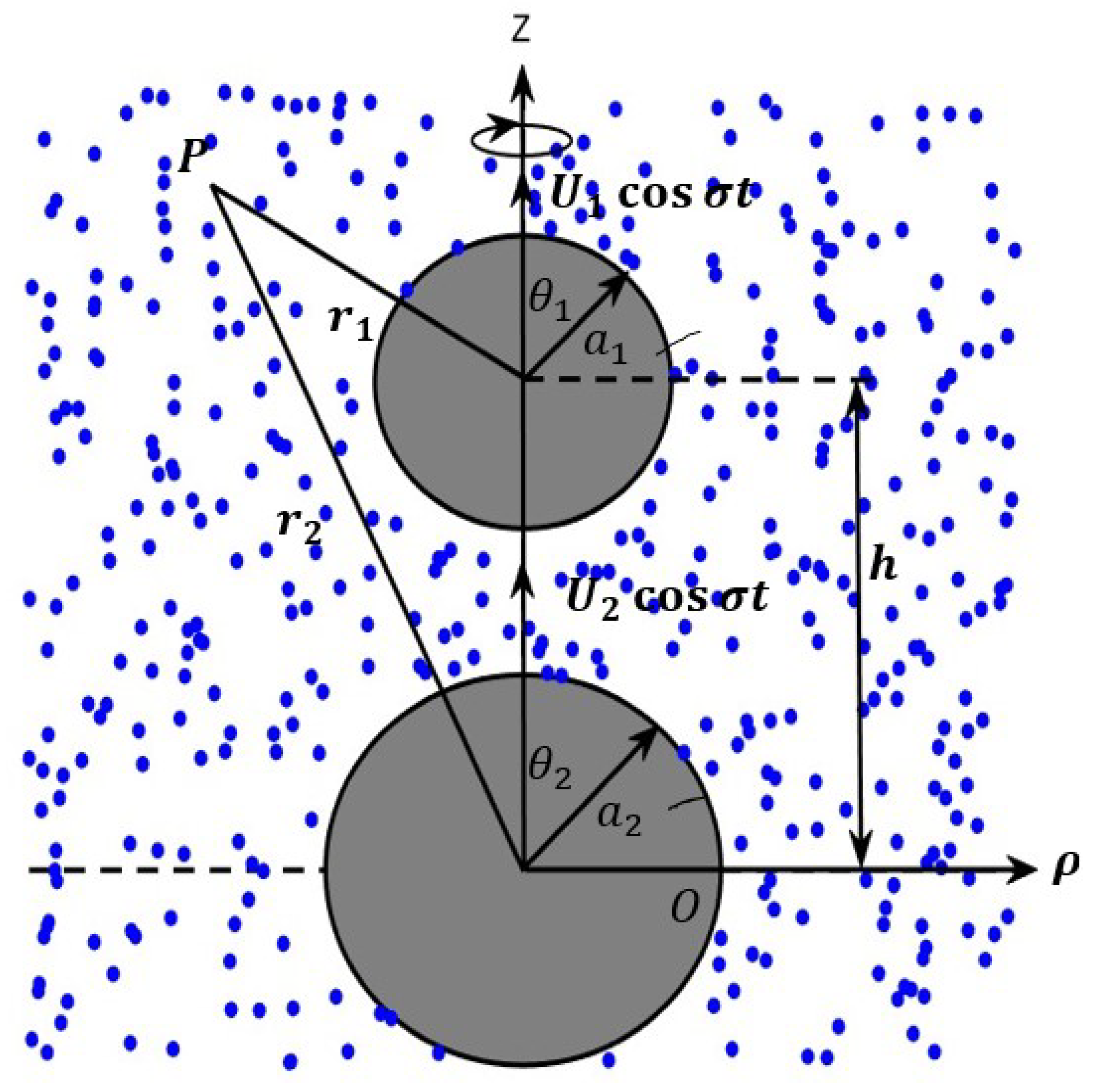
4. Interaction of Two Oscillating Spheres in a Porous Medium

The present section investigates the translation of motion of two rigid solid spheres oscillating within a porous medium saturated by a viscous fluid. The boundary conditions are implemented using a collocation technique. In the diagram model, we observed two translating solid spherical particles for radii a 1 and a 2 , these particles are moving with uniform velocities U 1 and U 2 , as shown in the geometry in Figure 1. Furthermore, we observed that the common line extends along the z-axis, allowing the two spherical particles to reach places that are external to each other, with a distance of h between their centers. Equation (3) has been used to compute the interaction of solid spherical particles. The velocity of the fluid flow equals zero at infinity. It is possible to determine the two systems, ( r 1 , θ 1 , ϕ ) and ( r 2 , θ 2 , ϕ ) , based on the centers of the two spheres a 1 and a 2 , respectively. The relation between ( r 1 , θ 1 ) and ( r 2 , θ 2 ) is given by
r 2 2 = r 1 2 + h 2 + 2 r 1 h cos θ 1 .
or by
r 1 2 = r 2 2 + h 2 2 r 2 h cos θ 2 .
Due to the presence of the spherical objects a j in the absence of the other particle, let q ( j ) , ( j = 1 , 2 ) be the velocity vector of the fluid. Let
q ( j ) = q r ( j ) ( r j , θ j ) e r j + q θ ( j ) ( r j , θ j ) e θ j .
In the case of the fluid extended at infinity, q r 0 , q θ 0 as r , then the kinematical and dynamical conditions are:
q r | r j = a j = U j cos θ j j = 1 , 2 ,
q θ | r j = a j = U j sin θ j + β j τ r j θ j j = 1 , 2 ,
where the slip length coefficient of the rigid spheres is β j ( j = 1 , 2 ) , which relies on the fluid environment and flatness of the spheres. The principle of superposition can be used for the following:
q r ( r 1 , θ 1 ; r 2 , θ 2 ) = q r ( 1 ) ( r 1 , θ 1 ) + q r ( 2 ) ( r 2 , θ 2 ) ,
q θ ( r 1 , θ 1 ; r 2 , θ 2 ) = q θ ( 1 ) ( r 1 , θ 1 ) + q θ ( 2 ) ( r 2 , θ 2 ) ,
Applying Equations (18)–(20) into (31) and (32), the normal and tangential velocities and the tangential stress function can be built up as follows:
q r ( r j , θ j ) = j = 1 2 n = 2 A n ( j ) r j n 1 + B n ( j ) r 3 2 K n 1 2 ( σ r j ) P n 1 ( cos θ j ) ,
q θ ( r j , θ j ) = j = 1 2 n = 2 [ ( 1 n ) A n ( j ) r j n 1 + B n ( j ) r j 3 2 n K n 1 2 ( σ r j ) σ r j K n + 1 2 ( σ r j ) ] n ( cos θ j ) sin θ j ,
τ r θ ( r j , θ j ) = j = 1 2 n = 2 [ 2 ( n 2 1 ) A n ( j ) r j n 2 + B n ( j ) r j 5 2 ( 2 n ( n 2 ) + σ 2 r j 2 ) K n 1 2 ( σ r j ) + 2 σ r j K n + 1 2 ( σ r j ) ] n ( cos θ j ) sin θ j .
Invoking the boundary conditions (29) and (30) and using Equations (33)–(35) along the spheres surfaces we obtain:
n = 2 A n ( 1 ) a 1 n 1 + B n ( 1 ) a 1 3 2 K n 1 2 ( σ a 1 ) P n 1 ( cos θ 1 ) + n = 2 A n ( 2 ) r 2 n 1 + B n ( 2 ) r 2 3 2 K n 1 2 ( σ r 2 ) r 1 = a 1 P n 1 ( cos θ 2 ) = U cos θ 1 ,
n = 2 A n ( 1 ) r 1 n 1 + B n ( 1 ) r 1 3 2 K n 1 2 ( σ r 1 ) P n 1 ( cos θ 1 ) + n = 2 A n ( 2 ) a 2 n 1 + B n ( 2 ) a 2 3 2 K n 1 2 ( σ a 2 ) r 2 = a 2 P n 1 ( cos θ 2 ) = U cos θ 2
( cos θ 1 ) sin θ 1 n = 2 [ ( 1 n ) 1 + 2 ( n + 1 ) β 1 μ a 1 2 A n ( 1 ) a 1 n 1 + B n ( 1 ) a 1 3 2 ( n β 1 μ a 1 1 ) ( σ 2 a 1 2 + 2 n ( n 2 ) ) K 1 2 ( σ a 1 ) σ a 1 1 + 2 β 1 μ a 1 2 K 1 2 ( σ a 1 ) ] + ( cos θ 2 ) sin θ 2 n = 2 [ ( 1 n ) 1 + 2 ( n + 1 ) β 1 μ r 2 2 A n ( 2 ) r 2 n 1 + B n ( 2 ) r 2 3 2 ( n β 1 μ r 2 1 ) ( σ 2 r 2 2 + 2 n ( n 2 ) ) K 1 2 ( σ r 2 ) σ r 2 1 + 2 β 1 μ r 2 2 K 1 2 ( σ r 2 ) ] | r 1 = a 1 = U 1 sin θ 1
( cos θ 1 ) sin θ 1 n = 2 [ ( 1 n ) 1 + 2 ( n + 1 ) β 2 μ r 1 2 A n ( 1 ) a 1 n 1 + B n ( 1 ) r 1 3 2 ( n β 2 μ r 1 1 ) ( σ 2 r 1 2 + 2 n ( n 2 ) ) K 1 2 ( σ r 1 ) σ r 1 1 + 2 β 2 μ r 1 2 K 1 2 ( σ r 1 ) ] | r 2 = a 2 + ( cos θ 2 ) sin θ 2 n = 2 [ ( 1 n ) 1 + 2 ( n + 1 ) β 2 μ a 2 2 A n ( 2 ) a 2 n 1 + B n ( 2 ) a 2 3 2 ( n β 2 μ a 2 1 ) ( σ 2 a 2 2 + 2 n ( n 2 ) ) K 1 2 ( σ a 2 ) σ a 2 1 + 2 β 2 μ a 2 2 K 1 2 ( σ a 2 ) ] = U 2 sin θ 2
The method of Gaussian elimination is used to solve the linear algebraic Equations (36)–(39) to determine the unknown coefficients A n ( j ) , B n ( j ) j = 1 , 2 and then the hydrodynamic drag force can be evaluated. The in-phase and out-of-phase for the two spheres are obtained from Equations (24) and (25) and we have the following:
χ j = Re F j F , χ j = Im F j F ,
where
F ( j ) = σ 2 ( V ( j ) + 2 π A 2 ( j ) ) , j = 1 , 2 .

5. Numerical Method for the Problem Undertaken

There are numerical solutions employed in Nanda Kishore’s [27,28] studies that typically involve computational fluid dynamics (CFD) techniques, such as the finite element method (FEM) and finite volume method (FVM), which discretize the flow domain to analyze particle interactions. Additionally, [29] analyzes the peristaltic behavior of an Eyring–Powell fluid in a non-uniform porous channel, highlighting the impact of channel characteristics on fluid dynamics, particularly in relation to blood flow in small arteries. Various computational algorithms, including the SIMPLE algorithm for solving the Navier–Stokes equations, are also utilized to effectively simulate and analyze the complex dynamics of particles in fluid flows. Furthermore, Keh and Huang [7] introduced the numerical method used, which is a combination of the method of distributed internal singularities and a boundary-collocation technique such as:
  • Method of Distributed Internal Singularities: This method involves distributing a set of Sampson spherical singularities along the axis of revolution within a prolate particle or on the fundamental plane within an oblate particle. This approach helps in finding the general solution for the fluid velocity field that satisfies the boundary conditions at infinity.
  • Boundary-Collocation Technique: After obtaining the general solution for the fluid velocity field, the boundary-collocation technique is applied to satisfy the slip condition on the surface of the translating particle. This technique is used to determine the unknown coefficients in the solution, ensuring that the boundary conditions are met accurately.
  • Convergence Behavior: The method demonstrates good convergence behavior for various cases, allowing for reliable calculations of the drag force exerted on the particle by the fluid. The results obtained using this method show excellent agreement with exact solutions for special cases, such as a sphere and a no-slip spheroid, as well as with approximate analytical solutions for slip spheroids.
To fulfill the boundary condition along the entire semicircular arc of a sphere, it is necessary to solve an infinite set of unknown constants. The boundary-collocation technique resolves this issue by applying the boundary condition at a finite number of discrete points on the arc, which enables the truncation of the infinite series into finite representations. By enforcing the boundary condition at N discrete points, the series is truncated after N terms, resulting in a system of 2 N simultaneous linear equations. These equations can be solved using standard matrix-reduction methods to determine the unknown constants. The precision of this truncation can be improved by increasing N, and the truncation error diminishes as N approaches infinity.
Overall, this combination of methods provides a robust framework for analyzing the axisymmetric creeping flow generated by slip particles in a viscous fluid. This method discusses the selection of points along the semicircular arc of a sphere for applying boundary conditions in fluid dynamics. The first point chosen is h = π 2 , as it defines the projected area of the particle normal to the motion. Points h = 0 and h = π are also significant, but using these can lead to a singular coefficient matrix in the equations for the unknown constants B n and D n . To avoid this issue while maintaining symmetry, four basic collocation points are selected: h = a , h = π 2 a , h = π 2 + a , and h = π a . The optimal value for a is determined to be 0 . 01 , allowing the numerical results for drag force to converge to at least four significant figures. With a sufficient number of well-distributed collocation points, the solution for drag force will converge, accurately approximating the particle’s shape regardless of its actual form or boundary conditions. The passage also refers to figures illustrating that the contour shape of the surface, where ψ = 0 can closely align with the particle shape through judicious point selection.

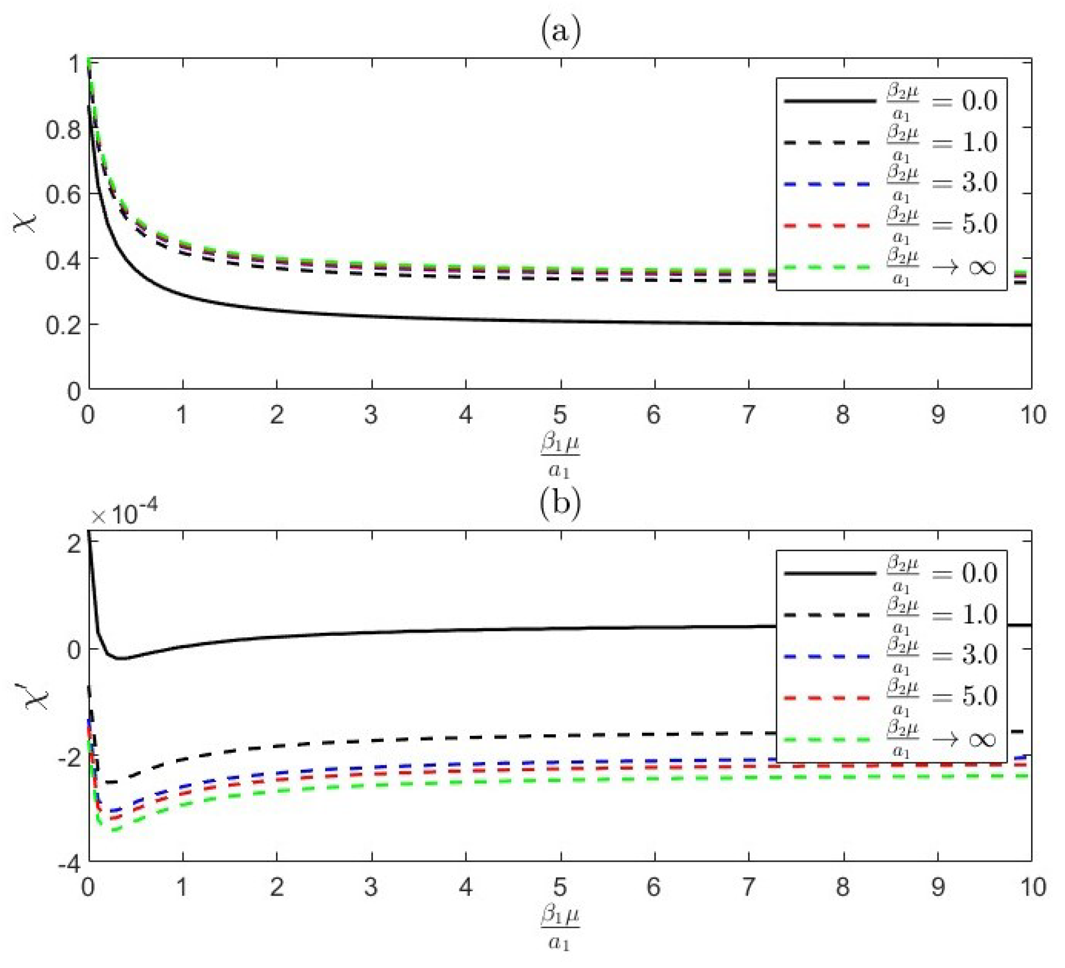
6. Effect of Slip Coefficient

Keh and Huang [7] mention that when solving the Navier–Stokes equations, it is commonly assumed that there is no slippage at solid–fluid interfaces, which oversimplifies the actual transport processes. Experimental and theoretical studies have shown that adjacent fluid, especially slightly rarefied gas, can slip frictionally over solid surfaces. This slipping is believed to be proportional to the local tangential stress at the surface, as long as the velocity gradient is small. The proportionality constant, known as the ’slip coefficient’ ( β 1 ), relates to the fluid viscosity ( μ ) and can be interpreted as a length, suggesting that fluid motion mimics a scenario where the solid surface is displaced inward by β / μ . Basset has established that the drag force on a translating rigid sphere with a slip-flow boundary condition is defined accordingly.
F = 6 π μ U a β a + 2 μ β a + 3 μ ,
where U represents the translational velocity of the particle. As μ approaches 1, there is no slip at the surface of the particle, and Equation (42) simplifies to the well-known Stokes law. In the extreme case where μ = 0 , there is a complete slip at the particle surface, causing the particle to behave like a spherical inviscid gas bubble. The slip coefficient in Equation (42) has been experimentally determined for various scenarios and has been found to align with the general kinetic theory of gases. It can be calculated using the following relation:
β = β m μ ,
where denotes the mean free path of a gas molecule, and β m is a dimensionless constant associated with gas–kinetic slip. This constant is semi-empirically linked to the momentum accommodation coefficient β m at the solid surface by the relation β m ( 2 f m ) f m . While β m is influenced by the characteristics of the surface, analysis of experimental data indicates that it typically falls within the range of 1.0 to 1.5 . It is important to note that the slip-flow boundary condition is applicable not only to gas–solid surfaces in the continuum regime (where the Knudsen number / a is approximately 1) but also seems to hold true in certain cases beyond this regime. There have been a number of authors who have used different parameters for the slip, for example, [5,8]. Consequently, since slip length can be difficult to measure precisely, it is frequently estimated using molecular dynamics simulations or flow experiments. To provide an accurate evaluation, surface characteristics, and flow conditions must be carefully controlled. All things considered, slip length is an important metric in contemporary fluid mechanics, particularly in applications involving complicated fluids, sophisticated material surfaces, and micro/nano-scale flows. Innovations in lowering friction, increasing flow rates, and creating effective microfluidic devices can result from an understanding of and control over slip length. The hypothetical distance from the wall to the solid surface where this velocity would be zero is known as the slip length. This may be seen by extending the linear profile of the fluid velocity close to the wall.
These slip conditions have been derived from physical observations or theoretical analyses. One of the important boundary conditions is the no-slip condition, which states that the velocity of the fluid at the boundary is the same as that of the boundary. As part of his study, [8] investigated the oscillating problem for viscous fluids near walls with partial slip boundary conditions, and linearized the Naiver–Stokes equations. Considering both the compressible and incompressible fluid, the slip length determining the boundary condition varies with frequency. The theoretical analysis is particularly useful for studying the frequency dependence of the boundary condition. The main point of our analysis is the effect of a wall with partial-slip boundary conditions on the the motion of a particle regardless of the type of fluid flow, whether it is compressible or incompressible, as the notation
β = ω ρ 0 c 0 2 , μ = ω c , c = c 0 [ 1 i β 4 3 η + η v 1 2
where ρ 0 is the fluid density, c 0 is the long-wave sound velocity, c is the frequency, and η v is the volume viscosity. The analysis reveals that a frequency-dependent slip length concept may be useful in describing dynamic surface phenomena in liquids. These expressions are different when dealing with incompressible flow, as the continuity equation is reduced when dealing with incompressible flow.

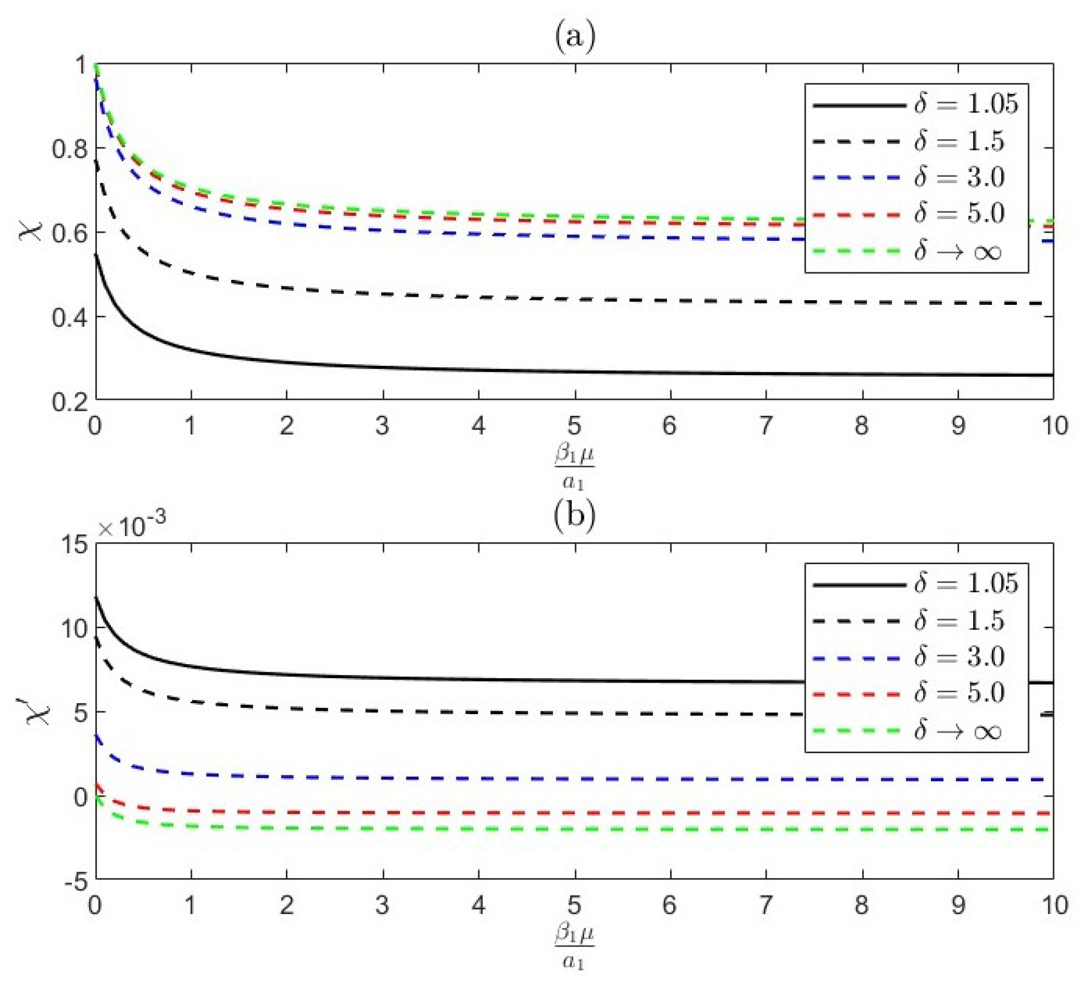
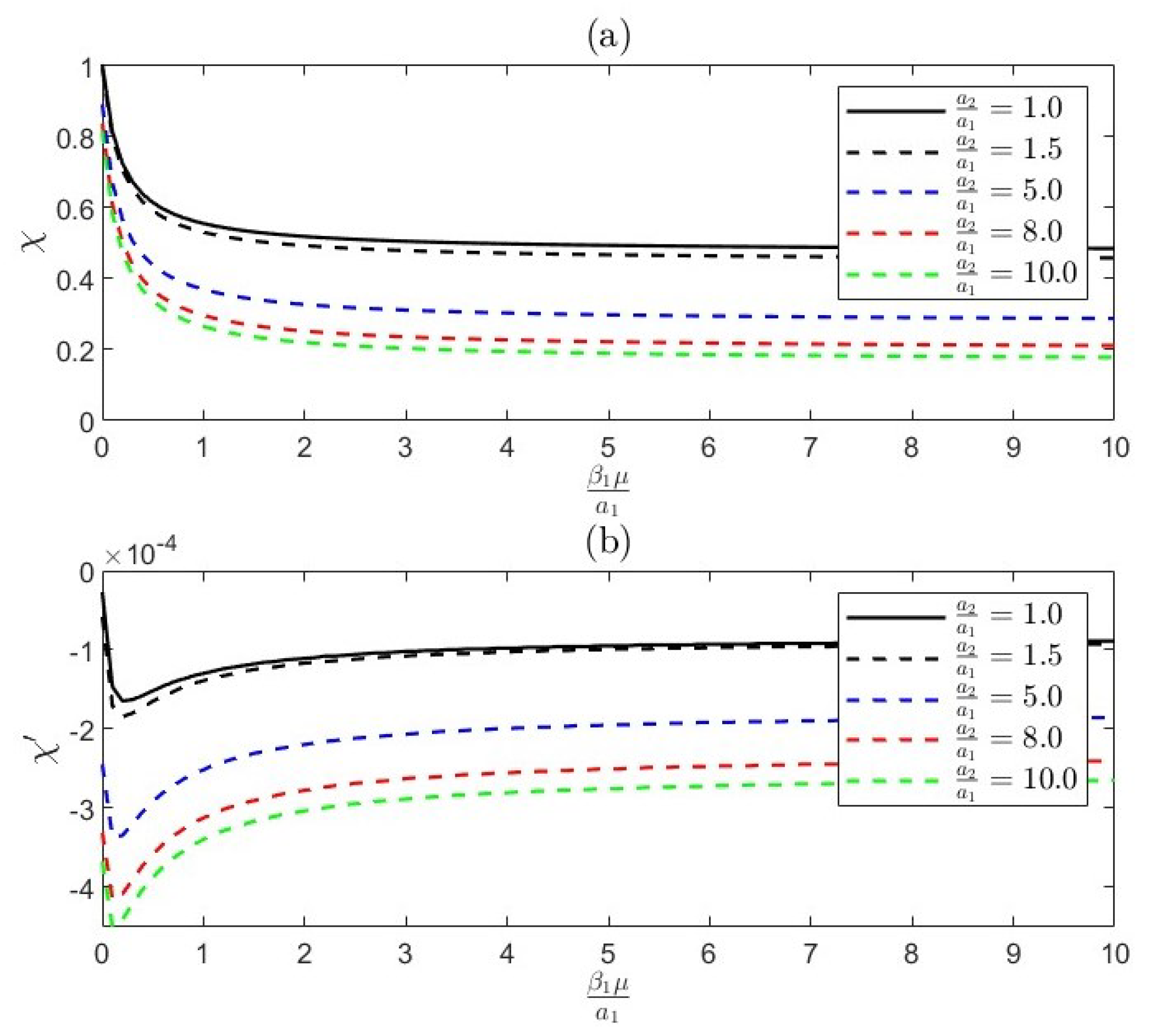
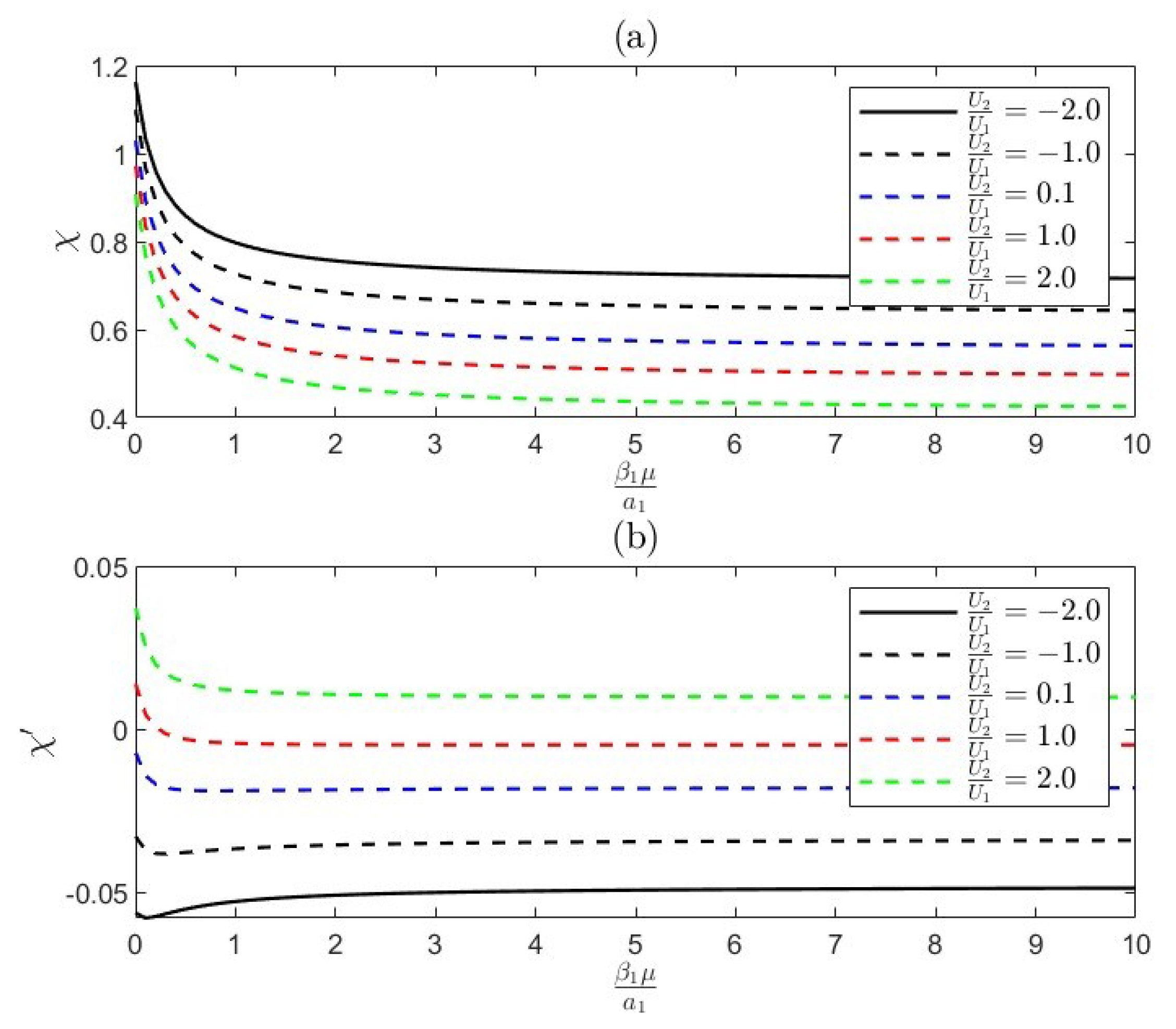
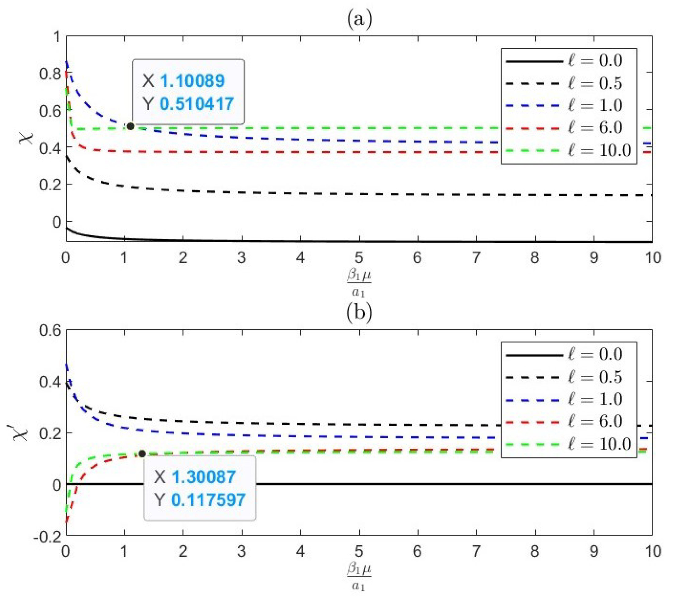
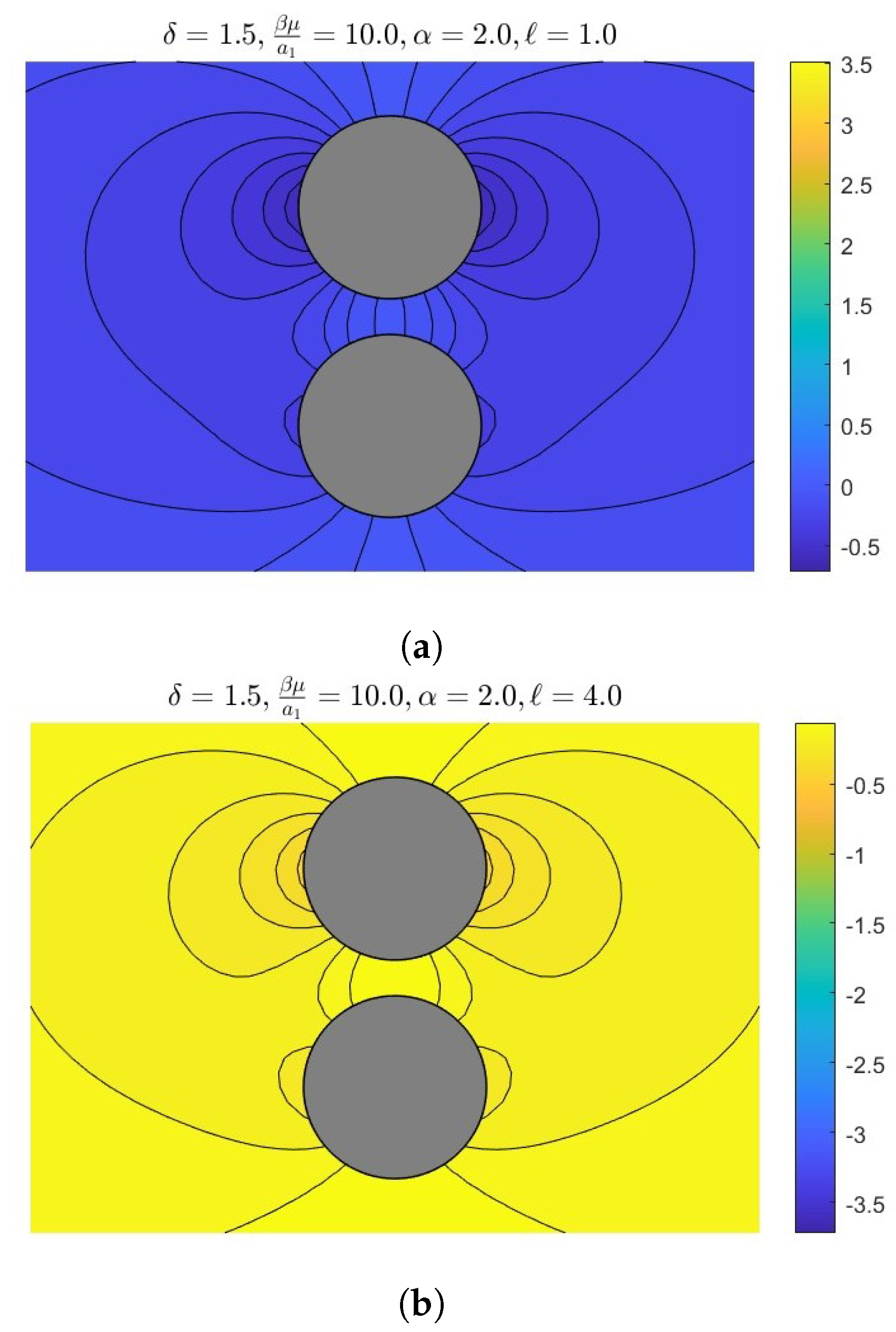
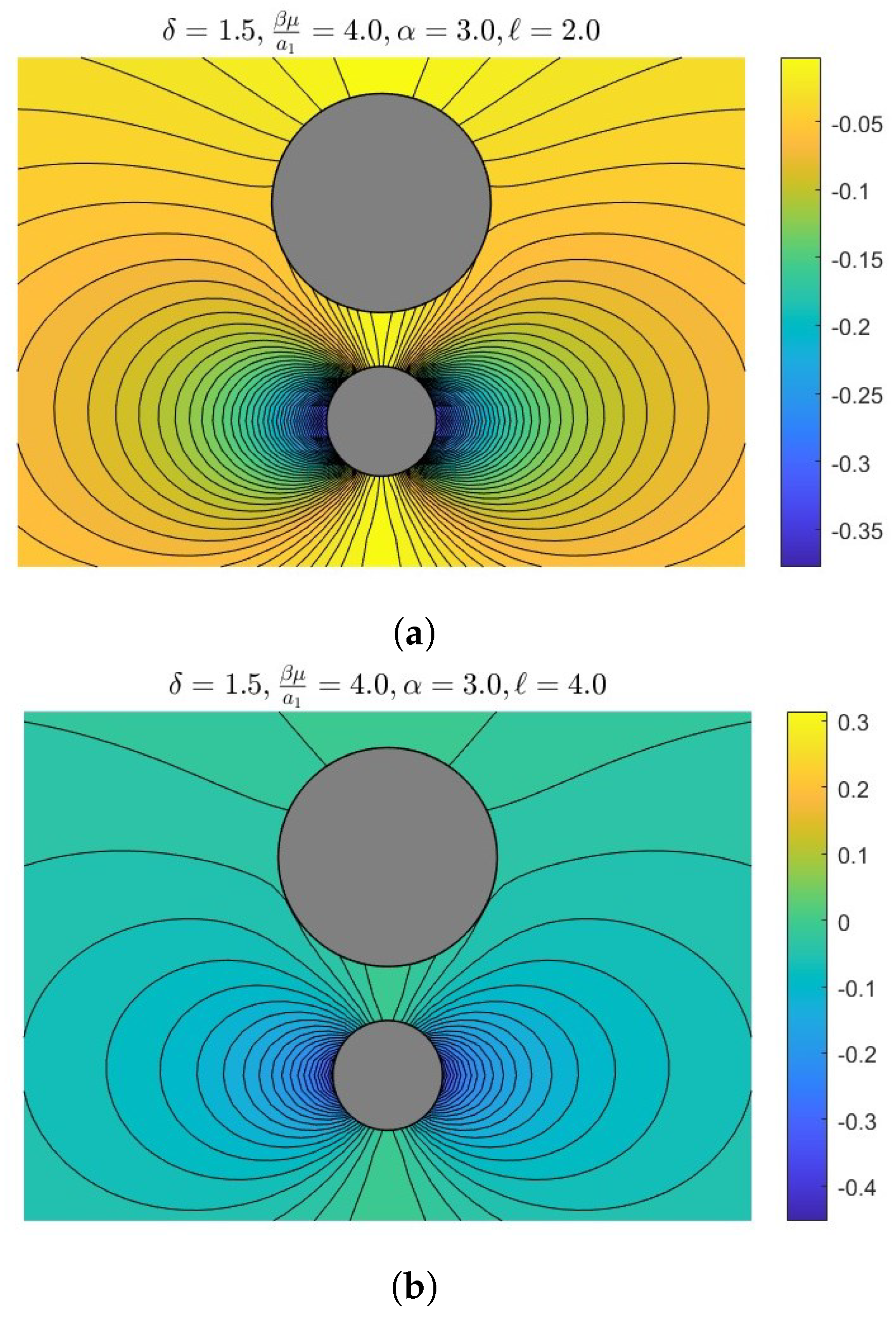
7. Results and Numerical Discussion

The Stokes–Brinkman problem concerns the interaction of two rigid spheres immersed in an unbounded porous medium under the impact of a slip regime. This involves computing the normalized drag force coefficients, χ and χ , which represent in-phase (IP) and out-of-phase (OP) interactions, respectively. Here, χ corresponds to the scenario where the crests of both waves pass a given point simultaneously, signifying in-phase alignment, while χ pertains to situations where the crest of one wave coincides with the trough of the other, indicating an out-of-phase condition with a phase difference of π radians. These coefficients are computed numerically and analytically across a range of parameters, including the velocity ratio U 2 U 1 , frequency , permeability range α , separation distance δ , and size ratio a 2 a 1 through Figure 2, Figure 3, Figure 4, Figure 5, Figure 6 and Figure 7 and streamlines from Figure 8, Figure 9 and Figure 10. Also, Table 1 presents th the normalized drag coefficients χ and χ experienced by the sphere of radius a 1 and Table 2 and Table 3 shows the comparison case of in-phase and out -of- phase. It was observed that as the distance between the spheres approaches near contact, the convergence rate diminishes monotonically. The results, obtained through the collocation scheme, converge satisfactorily to a significant number of figures, with N = 60 proving adequate to achieve convergence, even in the most challenging scenarios involving high frequencies. The feedback highlights the need for a deeper exploration of the physical mechanisms governing the interactions between two oscillating spheres in a Brinkman–Stokes fluid. Suggestions include elaborating on how fluid properties like viscosity and permeability influence drag forces and flow patterns, discussing the implications for industrial processes such as mixing and sedimentation, and addressing energy dissipation and thermodynamic efficiency in relation to oscillations. Enhancing figures with annotated streamlines and force diagrams is recommended to clarify the physics and contextualize findings, improving their relevance to chemical engineering and thermodynamics applications.
Figure 2 shows the IP and OP versus the velocity slip β 1 μ / a 1 for various values of β 2 μ / a 1 = ( 0 , 1 , 3 , 5 , ) at certain values of β 2 μ a 1 = 1.0 , U 2 U 1 = 2.0 , a 2 a 1 = 2.0 , = 0.1 , α = 0.4 . One basic premise is the in-phase relationship between slippages and drag force in a fluid system. This indicates that the direction of an item’s relative motion, or slippage, inside a fluid is directly opposed to the direction of the drag force exerted on the object as it moves through the fluid. To put it another way, as the slippage, or relative velocity, between the object and the fluid increases, the drag force, which acts to slow the object down, becomes stronger. This relationship can be seen in a number of phenomena, including the resistance that an automobile faces when traveling through the air or a boat when navigating through water. On the other side, the OP has the inverse influence of slippage parameters. The direction and magnitude of the drag force can be affected by external forces, object geometry, and fluid properties, among other factors that are frequently involved in out-of-phase relationships between drag force and slippages.
Figure 3 shows that the drag force exerted on the spheres for different values of β 2 μ a 1 = 1.0 , U 2 U 1 = 2.0 , a 2 a 1 = 2.0 , = 0.1 , α = 0.4 rises due to greater fluid resistance as the separation distance between them decreases. The specifics of this connection, however, are dependent on a number of variables, such as the medium’s porosity, the flow’s Reynolds number, and the spheres’ proportional size to the pore size. The drag force can exhibit a more complex nonlinear relationship, or even decrease at specific separation distances, which is referred to as an out-of-phase behavior. In rare circumstances, it might grow linearly with decreasing separation distance (in phase). This is especially clear when spheres get closer to one another in a small area because the hydrodynamic interactions between them might produce unanticipated drag force patterns. Here, there is more significance of slippage conditions, frequency, and porosity to inverse this influence in the case of IP. In general, the close proximity produces a strong interaction, increases drag, and reduces effective slippage, but a larger distance causes the drag forces to approach isolated behavior, and slippage effectively reduces drag.
Figure 4 exhibits the IP and OP for various values of the size ratio a 2 / a 1 = ( 1.0 , 1.5 , 5 , 8 , 10 ) at certain values of the relevant parameters δ = 1.5 , β 2 μ a 1 = 1.0 , U 2 U 1 = 2.0 , = 0.1 , α = 2.0 so that there are in-phase (IP) and out-of-phase (OP) interactions; the larger particles typically exert more force on the flow field, increasing the in-phase drag forces acting upon it and concurrently reducing the drag that the smaller particle experiences. The larger particle’s flow disturbances affect the slip velocity and the formation of the boundary layer around the smaller particle, which frequently results in a decrease in the smaller particle’s resistive drag.
Figure 5 indicates the complex interactions between the fluid flow surrounding each sphere and the relative motion of the spheres affect how the velocities of two spheres affect in-phase and out-of-phase drag forces in the presence of slippage. The interplay of wake regions, boundary layer interference, and the kind of slippage at the fluid–sphere contact are some of the elements that contribute to this complexity. In this figure, there are more influences of velocity ratios U 2 / U 1 = ( 2 , 1 , 0.1 , 1 , 2 ) on the drag forces such that the compressed fluid and interference between the spheres generate a rise in in-phase drag force when both spheres are moving in the same direction and at the same speed, known as in-phase motion. Conversely, the total inertia of the fluid displaced by both spheres causes an increase in out-of-phase drag. The out-of-phase drag, on the other hand, exhibits a more complex behavior as fluctuating pressure fields and varying fluid inertia lead to non-linear effects on the reactive drag force. In contrast, during out-of-phase motion, where the spheres move with opposite velocities, the in-phase drag can increase due to strong shearing forces and complex boundary layer interactions.
Figure 6 expresses the impacts of the permeability α = ( 0 , 0.5 , 1 , 4 , 10 ) on the drag forces such that by varying the fluid flow resistance, the permeability of a porous medium influences drag forces on particles: low permeability restricts fluid movement, increasing in-phase drag through increased viscous resistance and out-of-phase drag due to greater fluid inertia and stronger interactions with the medium’s structure. Conversely, high permeability α = 10 allows easier fluid passage, reducing both in-phase drag due to lower viscous resistance and out-of-phase drag due to decreased fluid inertia. This behavior is illustrated in the figure, where the drag force for in-phase interactions decreases while the out-of-phase drag increases, likely due to the type of out-of-phase force and also the slippage conditions on the surface of the particles.
Figure 7 displays the impact of frequency = ( 0 , 0.5 , 1 , 6 , 10 ) on the drag force coefficients so we found that the frequency of oscillations significantly impacts drag forces on particles. At low frequencies, in-phase drag is dominant, as viscous forces primarily resist particle motion, while the out-of-phase drag related to fluid inertia is minimal. As the frequency increases, the out-of-phase drag becomes more significant due to the enhanced inertial effects of the fluid. At high frequencies, the drag force may become dominated by out-of-phase components, and the boundary layer around the particles becomes thinner, increasing viscous resistance. The combined effect results in a complex interplay between in-phase and out-of-phase drag forces, with the frequency determining their relative magnitudes.
Figure 8, Figure 9 and Figure 10 present some of the streamlines over the two solid spheres for different parameters such that in a viscous fluid, size ratios, slippage, separation distance, and the permeability of the surrounding medium all affect how streamlines behave around two solid spheres. As the distance between the spheres becomes smaller, there is a significant distortion in the streamlines between them, which causes the flow to accelerate and also causes complicated wake interactions. When size ratios are bigger, the larger sphere dominates the flow, and the smaller sphere experiences different streamline patterns and wake zones. The reduction in viscous drag caused by slippage at the sphere surfaces facilitates greater fluid flow around the spheres, hence mitigating the distortion of streamlines in their vicinity. Low permeability in a porous material limits the streamlines, making the fluid travel along constrained routes and increasing flow resistance, whereas high permeability permits more uniform and less disrupted streamlines. All these elements work together to produce a complicated flow field that, depending on the circumstances, is defined by different degrees of streamline curvature, separation, and wake interaction. Furthermore, The figures illustrate the impact of frequency on the flow patterns around two oscillating spherical particles in a viscous fluid. At lower frequency (Figure 9a), the flow field exhibits a smoother, more gradual variation. Increasing the frequency (Figure 9b) results in a more complex, rapidly varying flow field, with tighter, more distorted streamlines, indicating stronger fluid–particle interactions. The higher frequency case shows a more pronounced coupling between the particles, while the lower frequency case exhibits a weaker interaction. Overall, the figures demonstrate the significant influence of the frequency parameter on the dynamics of the oscillating particle system. Additionally, this study effectively underscores the promising applications of this research in wastewater treatment, reactor design, and microfluidics. However, further exploration would enhance its impact. For instance, delving into how the observed permeability and slippage effects could be translated into concrete design principles or performance optimizations for wastewater management and catalytic processes would be highly beneficial. Such an elaboration would not only bolster the practical relevance of the findings but also provide actionable insights that could drive improvements in these critical fields.

8. Conclusions

This study focuses on the motion of two oscillating hard spheres in Stokes flow, specifically examining their oscillation along the symmetry axis. It explores how permeability and slip length affect the oscillation of the rigid spheres. The findings serve as a valuable constraint for previous research involving clear fluids without slippage, as well as for studies that consider clear fluids, ultimately yielding positive results for scenarios with no slip. By using a collocation approach, force coefficients are calculated for both in-phase and out-of-phase movements. Various factors affect drag force coefficients, including radius ratio, separation distance, velocity ratio, permeability, frequency, slip length, and streamline patterns. It finds that closer proximity of the spheres increases the in-phase drag coefficient due to enhanced viscous interactions and disturbed flow. Conversely, the out-of-phase drag coefficient is influenced by the combined inertia of the fluid displaced by the spheres, which varies with their wake interactions. Larger spheres experience greater drag forces, while smaller spheres have altered drag coefficients due to changes in flow patterns. Furthermore, slippage at spherical surfaces reduces viscous resistance and effective drag, while high permeability facilitates smoother flow and lower drag, in contrast with low permeability, which increases drag. The main findings of this study are:
  • The radius ratio influences flow dynamics, with smaller ratios leading to stronger interactions and increased drag due to closer proximity. Larger ratios result in weaker interactions, allowing flow to bypass the smaller body.
  • Permeability is a property of materials that determines how much fluid can flow through them, which influences drag forces. Higher permeability can reduce drag by allowing fluid to pass through a body, leading to complex interactions.
  • The distance between bodies is critical for interaction dynamics, with decreased separation enhancing hydrodynamic coupling. This can result in in-phase interactions that increase drag or out-of-phase interactions that reduce it.
  • In-phase interactions occur when bodies move together, amplifying drag through constructive interference. Out-of-phase interactions happen when they move oppositely, leading to destructive interference and reduced drag, influenced by radius ratio, permeability, and separation distance.
  • Slippage length refers to the distance over which fluid can slide past a surface without sticking. Increased slippage can reduce drag by allowing smoother fluid flow around the bodies, altering the interaction dynamics, and potentially leading to different coupling behaviors based on the extent of slippage.
The study has several limitations, including a narrow parameter range, a lack of consideration for long-term effects, and a limited exploration of practical applications. To address these issues, it is essential to expand the parameter ranges, incorporate complex models validated through experiments, and provide a deeper understanding of mechanisms using principles from chemical engineering and thermodynamics. Additionally, enhancing figures with annotations, analyzing long-term stability, and linking findings to real-world applications will strengthen the study’s robustness and practical relevance.

Author Contributions

Conceptualization, A.M.A.; writing—original draft preparation, A.M.A. and H.H.T.; writing—review and editing, H.H.T. and S.E.-S. All authors have read and agreed to the published version of the manuscript.

Funding

This research was funded by Algatheem, A.M. at the Deanship of Graduate Studies and Scientific Research at University of Bisha for supporting this work through the Fast-Track Research Support Program.

Data Availability Statement

The data presented in this study are available on request from the corresponding author.

Acknowledgments

The authors are thankful to the Deanship of Graduate Studies and Scientific Research at University of Bisha for supporting this work through the Fast-Track Research Support Program.

Conflicts of Interest

The authors declare no conflicts of interest.

References

  1. El-Sapa, S.; Alhejaili, W. On the hydrodynamic interaction of two coaxial spheres oscillating in a viscous fluid with a slip regime. Zamm J. Appl. Math. Mech. 2023, 103, e20210050. [Google Scholar] [CrossRef]
  2. El-Sapa, S. The force on a magneto-spherical particle oscillating in a viscous fluid perpendicular to an impermeable planar wall with slippage. Eur. J. Pure Appl. Math. 2022, 15, 1376–1401. [Google Scholar] [CrossRef]
  3. Chaudhary, R.C.; Jain, A. Combined heat and mass transfer effects on MHD free convection flow past an oscillating plate embedded in a porous medium. Rom. J. Phys. 2007, 52, 505–524. [Google Scholar]
  4. Teng, B.; Luo, W.; Chen, Z.; Kang, B.; Chen, L.; Wang, T. A comprehensive study of the effect of Brinkman flow on the performance of hydraulically fractured wells. J. Pet. Sci. Eng. 2022, 213, 110355. [Google Scholar] [CrossRef]
  5. Albalawi, W.; Taha, H.H.; El-Sapa, S. Effect of the permeability on the interaction between two spheres oscillating through Stokes-Brinkman medium. Heliyon 2023, 9, e14396. [Google Scholar] [CrossRef]
  6. Faltas, M.S.; El-Sapa, S. Rectilinear oscillations of two spherical particles embedded in an unbounded viscous fluid. Microsyst. Technol. 2019, 25, 39–49. [Google Scholar] [CrossRef]
  7. Keh, H.J.; Huang, C.H. Slow motion of axisymmetric slip particles along their axes of revolution. Int. J. Eng. Sci. 2004, 42, 1621–1644. [Google Scholar] [CrossRef]
  8. Felderhof, B.U. Hydrodynamic force on a particle oscillating in a viscous fluid near a wall with dynamic partial-slip boundary condition. Phys. Rev. 2012, 85, 046303. [Google Scholar] [CrossRef]
  9. Lawrence, C.; Weinbaum, S. The force on an axisymmetric body in linearized, time-dependent motion: A new memory term. J. Fluid Mech. 1986, 171, 209–218. [Google Scholar] [CrossRef]
  10. Ardekani, A.M.; Range, R.H. Unsteady motion of two solid spheres in Stokes flow. Phys. Fluids 2006, 18, 103306. [Google Scholar] [CrossRef]
  11. Basak, S.; Raman, A. Hydrodynamic coupling between micromechanical beams oscillating in viscous fluids. Phys. Fluids 2007, 19, 017105. [Google Scholar] [CrossRef]
  12. Brenner, H. The slow motion of a sphere through a viscous fluid towards a plane surface. Chem. Eng. Sci. 1961, 16, 242–251. [Google Scholar] [CrossRef]
  13. Chadwick, R.S.; Liaot, Z. High-frequency oscillations of a sphere in a viscous fluid near a rigid plane. Siam Rev. 2008, 50, 313–322. [Google Scholar] [CrossRef]
  14. Chen, S.H.; Keh, H.J. Axisymmetric motion of two spherical particles with slip surfaces. J. Colloid Interface Sci. 1995, 171, 63–72. [Google Scholar] [CrossRef]
  15. Happel, J.; Brenner, H. Low Reynolds Number Hydrodynamics: With Special Applications to Particulate Media; Springer Science and Business Media: Berlin, Germany, 2012; p. 1. [Google Scholar]
  16. Jeffrey, D.J.; Onishi, Y. Calculation of the resistance and mobility functions for two unequal rigid spheres in low-Reynolds-number flow. J. Fluid Mech. 1984, 139, 261–290. [Google Scholar] [CrossRef]
  17. Faltas, M.S.; Nashwan, M.G.; Ahmed, B.A.; Hamdy, P. Axisymmetric motion of two spherical particles in a Brinkman medium with slip surfaces. Chin. J. Phys. 2024, 89, 1377–1399. [Google Scholar] [CrossRef]
  18. Yadav, P.K.; Yadav, N. A study on the flow of couple stress fluid in a porous curved channel. Comput. Math. Appl. 2023, 152, 1–15. [Google Scholar] [CrossRef]
  19. Ramesh, K. Effects of slip and convective conditions on the peristaltic flow of couple stress fluid in an asymmetric channel through porous medium. Comput. Methods Programs Biomed. 2016, 135, 1–14. [Google Scholar] [CrossRef]
  20. Madasu, K.P.; Sarkar, P. Couple stress fluid past a sphere embedded in a porous medium. Arch. Mech. Eng. 2022, 69, 5–19. [Google Scholar] [CrossRef]
  21. Khan, N.A.; Mahmood, A.; Ara, A. Approximate solution of couple stress fluid with expanding or contracting porous channel. Eng. Comput. Int. J. Comput. Aided Eng. Softw. 2013, 30, 399–408. [Google Scholar]
  22. Maurya, P.K.; Deo, S.; Maurya, D.K. Couple stress fluid flow enclosing a solid sphere in a porous medium: Effect of magnetic field. Phys. Fluids 2023, 35, 072006. [Google Scholar] [CrossRef]
  23. El-Sapa, S.; Alsudais, N.S. Effect of magnetic field on the motion of two rigid spheres embedded in porous media with slip surfaces. Eur. Phys. J. 2021, 44, 68. [Google Scholar] [CrossRef] [PubMed]
  24. Ochoa-Tapia, J.A.; Whitaker, S. Momentum transfer at the boundary between a porous medium and a homogeneous fluid—ii. comparison with experiment. Int. J. Heat Mass Transf. 1995, 38, 2647–2655. [Google Scholar] [CrossRef]
  25. Ochoa-Tapia, J.A.; Whitaker, S. Momentum transfer at the boundary between a porous medium and a homogeneous fluid—i. theoretical development. Int. J. Heat Mass Transf. 1995, 38, 2635–2646. [Google Scholar] [CrossRef]
  26. Breugem, W.-P. The effective viscosity of a channel-type porous medium. Phys. Fluids 2007, 19, 103104. [Google Scholar] [CrossRef]
  27. Kishore, N. Flow and drag phenomena of tandem spheroid particles at finite Reynolds numbers. Ind. Eng. Chem. Res. 2012, 51, 553–554. [Google Scholar] [CrossRef]
  28. Kishore, N. Numerical investigation of interaction between spheroid particles in tandem arrangement at moderate Reynolds numbers. Ind. Eng. Chem. Res. 2012, 51, 555–556. [Google Scholar] [CrossRef]
  29. Prathiksha, P.; Manjunatha, G.; Choudhari, R.; Vaidya, H.; Prasad, K.V. Impact of Variable Fluid Properties on the Peristaltic Flow of Eyring-powell Fluid through Porous Medium: Applications to Hemodynamics. CFD Lett. 2025, 17, 114–139. [Google Scholar] [CrossRef]
Figure 1. Model of two migration spheres oscillating through a porous fluid.
Mathematics 13 00218 g001
Figure 2. (a) In-phase and (b) out-of-phase distributions for various values of β 2 μ a 1 with δ = 1.05 , U 2 U 1 = 4.0 , a 2 a 1 = 2.0 , = 0.1 , α = 2.0 .
Mathematics 13 00218 g002
Figure 3. (a) In-phase and (b) out-of-phase distributions for various values of slip δ with β 2 μ a 1 = 1.0 , U 2 U 1 = 2.0 , a 2 a 1 = 2.0 , = 0.1 , α = 0.4 .
Mathematics 13 00218 g003
Figure 4. (a) In-phase and (b) out-of-phase distributions with various values of a 2 a 1 , δ = 1.5 , β 2 μ a 1 = 1.0 , U 2 U 1 = 2.0 , = 0.1 , α = 2.0 .
Mathematics 13 00218 g004
Figure 5. In-phase and out-of-phase distributions with δ = 1.05 , β 2 μ a 1 = 1.0 , a 2 a 1 = 2.0 , = 0.5 , α = 1.0 .
Mathematics 13 00218 g005
Figure 6. In-phase and out-of-phase distributions with δ = 1.05 , β 2 μ a 1 = 1.0 , U 2 U 1 = 2.0 , a 2 a 1 = 5.0 , = 2.0 .
Mathematics 13 00218 g006
Figure 7. In-phase and out-of-phase distributions with δ = 1.05 , β 2 μ a 1 = 0.1 , U 2 U 1 = 2.0 , a 2 a 1 = 2.0 , = 0.1 .
Mathematics 13 00218 g007
Figure 8. The streamline distributions with different values of the relevant parameters for two equal spheres moving with the same velocity. (a,b) Two different parameter sets.
Mathematics 13 00218 g008
Figure 9. The streamlines distributions with different values of the relevant parameters for two equal spheres moving with the same velocity. (a,b) Two different parameter sets.
Mathematics 13 00218 g009
Figure 10. The streamline distributions with different values of the relevant parameters for two equal spheres moving with the same velocity. (a,b) Two different parameter sets.
Mathematics 13 00218 g010
Table 1. The in-phase and out-of-phase distributions on the sphere a 1 , where the two solid spheres move in the same direction with the same velocities and are equal in size at = 0.1 .
χ χ
α δ β  = 0.0 β  = 1.0 β β  = 0.0 β  = 1.0 β
1.010.7711170.7335210.7783140.008599−0.0003640.298957
2.00.8382070.6741750.5894010.0163920.0043800.009223
3.00.8822010.6901100.6212920.0199380.0060230.009225
4.00.9100870.7021680.6295550.0216120.0066410.002462
0.05.00.9290530.7110020.6371730.0223290.0068030.004330
(Ref. [1])6.00.9427500.7176410.6411790.0224950.0067150.003821
7.00.9531030.7227830.6447940.0223150.0064770.001978
8.00.9612010.7268710.6485140.0219090.0061430.004035
9.00.9677040.7301900.6496410.0213470.0057440.003694
10.00.9730330.7329320.6512540.0206780.0053030.001248
1.010.9314300.6757530.6019450.000731−0.000469−0.000600
2.00.9969310.6261330.5323150.000152−0.000590−0.000592
3.01.0000980.6224960.5278720.000003−0.000615−0.000598
4.00.9998690.6213680.526677−0.000009−0.000605−0.000585
1.05.00.9997860.6210700.526366−0.000006−0.000599−0.000579
6.00.9998020.6209980.526285−0.000003−0.000596−0.000576
7.00.9998390.6209870.526268−0.000002−0.000594−0.000575
8.00.9998730.6209920.526268−0.000001−0.000593−0.000574
9.00.9999000.6210000.526273−0.000001−0.000593−0.000574
10.00.9999210.6210090.5262790.000000−0.000593−0.000573
1.011.0351340.6001390.557121−0.0000020.0000350.000052
2.00.9916890.5615430.518993−0.0000020.0000400.000057
3.00.9958040.5652680.522658−0.0000010.0000420.000059
4.00.9978290.5669210.5242710.0000000.0000420.000059
4.05.00.9987590.5676610.5249910.0000000.0000420.000060
6.00.9992300.5680310.5253520.0000000.0000420.000060
7.00.9994920.5682360.5255500.0000000.0000420.000060
8.00.9996470.5683570.5256680.0000000.0000420.000060
9.00.9997450.5684330.5257420.0000000.0000420.000060
10.00.9998100.5684830.5257900.0000000.0000420.000060
1.011.0282990.7838020.7753810.0000000.0000110.000012
2.00.9859740.7484450.7402440.0000000.0000110.000012
3.00.9937090.7559270.7477150.0000000.0000110.000012
4.00.9968570.7588620.7506420.0000000.0000110.000012
10.05.00.9982330.7601310.7519080.0000000.0000110.000012
6.00.9989140.7607560.7525310.0000000.0000110.000012
7.00.9992870.7610970.7528710.0000000.0000110.000012
8.00.9995080.7612990.7530720.0000000.0000110.000012
9.00.9996460.7614250.7531970.0000000.0000110.000012
10.00.9997370.7615080.7532800.0000000.0000110.000012
Table 2. Comparison in the case of slippages and no porous for the cases of low and high frequency for the in-phase distributions on the sphere a 1 for two equal solid spheres moving in the same direction with the same velocities.
α δ β  = 0.0 β  = 1.0 β  = 4.0 β
1.050.5571320.6370360.7352400.768777
2.00.5866190.6501530.7822400.838207
3.00.5941370.6686750.8171600.882200
4.00.6060710.6840180.8407250.910086
0.15.00.6173480.6954400.8571410.929052
6.00.6248140.7040610.8691430.942749
7.00.6304660.7107450.8782810.953102
8.00.6362990.7160630.8854630.961200
9.00.6386500.7203860.8912510.967703
10.00.6404300.7239650.8960080.973032
1.050.4358250.4675910.7050441.018732
2.00.4215620.4529220.6867740.990985
3.00.4256870.4571210.6914280.995700
4.00.4273060.4587790.6933370.997810
4.05.00.4280060.4594960.6941720.998756
6.00.4283510.4598500.6945870.999230
7.00.4285390.4600430.6948130.999491
8.00.4286500.4601570.6949470.999646
9.00.4287200.4602280.6950310.999744
10.00.4287650.4602750.6950870.999808
1.050.8097210.8074640.8100991.010685
2.00.7877920.7855810.7881720.984705
3.00.7960680.7938580.7964720.993234
4.00.7992760.7970640.7996870.996631
10.05.00.8006580.7984450.8010730.998107
6.00.8013370.7991250.8017540.998836
7.00.8017080.7994950.8021260.999234
8.00.8019260.7997130.8023440.999469
9.00.8020630.7998500.8024810.999616
10.00.8021530.7999400.8025720.999713
1.051.0030351.0030241.0029201.009203
2.00.9759240.9759120.9758110.981947
3.00.9861210.9861090.9860070.992150
4.00.9900780.9900670.9899650.996113
5.00.9917840.9917730.9916710.997821
6.00.9926240.9926120.9925100.998662
7.00.9930810.9930700.9929680.999120
8.00.9933510.9933390.9932370.999391
9.00.9935200.9935080.9934060.999560
10.00.9936310.9936190.9935170.999671
Table 3. Comparison in the case of non-porous slippages for the cases of low and high frequency for the out-phase and out-of-phase distributions on the sphere a 1 for two equal solid spheres moving in the same direction with the same velocities.
α δ β  = 0.0 β  = 1.0 β  = 4.0 β
1.050.015649−0.0010630.0056870.008883
2.00.0092840.0039180.0120560.016392
3.00.0085860.0056250.0148940.019938
4.00.0020310.0064090.0162300.021612
0.15.00.0039900.0067480.0168020.022329
6.00.0030100.0068320.0169300.022494
7.00.0035700.0067560.0167820.022315
8.00.0041580.0065740.0164500.021909
9.00.0062800.0063190.0159920.021347
10.00.0026800.0060130.0154470.020678
1.050.1891260.133284−0.040952−0.014563
2.00.1830090.128790−0.038289−0.006118
3.00.1859640.131726−0.035146−0.002223
4.00.1870000.132731−0.034174−0.001029
4.05.00.1874350.133148−0.033788−0.000557
6.00.1876450.133350−0.033605−0.000335
7.00.1877590.133458−0.033508−0.000217
8.00.1878260.133522−0.033451−0.000149
9.00.1878670.133561−0.033417−0.000107
10.00.1878950.133587−0.033394−0.000079
1.050.2077640.1976060.121689−0.002832
2.00.2023560.1924110.118075−0.003537
3.00.2046110.1946560.120249−0.001363
4.00.2054710.1955070.121037−0.000647
10.05.00.2058400.1958720.121370−0.000355
6.00.2060210.1960510.121532−0.000215
7.00.2061190.1961480.121620−0.000140
8.00.2061770.1962050.121671−0.000097
9.00.2062140.1962410.121704−0.000069
10.00.2062380.1962650.121725−0.000052
1.050.0119200.0119040.011758−0.000139
2.00.0115980.0115820.011440−0.000180
3.00.0117200.0117040.011561−0.000070
4.00.0117670.0117510.011608−0.000033
5.00.0117870.0117710.011628−0.000018
6.00.0117970.0117810.011638−0.000011
7.00.0118020.0117870.011644−0.000007
8.00.0118060.0117900.011647−0.000005
9.00.0118080.0117920.011649−0.000004
10.00.0118090.0117930.011650−0.000003
Disclaimer/Publisher’s Note: The statements, opinions and data contained in all publications are solely those of the individual author(s) and contributor(s) and not of MDPI and/or the editor(s). MDPI and/or the editor(s) disclaim responsibility for any injury to people or property resulting from any ideas, methods, instructions or products referred to in the content.

