1. Introduction
As an efficient and reliable numerical method, the lattice Boltzmann Method (LBM) has been developing rapidly for roughly 40 years, this is why the numerical applications cover a wide range of engineering topics, for instance, aeronautics [
1], acoustics [
2], multi-phase-component flows [
3], porous medium [
4], rheology [
5], heat and mass transfer [
6], biofluids [
7], magnetic fluid [
8], image processing [
9], crystal growth [
10], and Partial Differential Equations (PDEs) [
11]. After many improvements, the methodology has progressed into a multi-functional interdisciplinary algorithm, covering subjects as fluid mechanics, mathematics, statistical mechanics, and thermal dynamics.
The prosperity of LBM undoubtedly benefits from the famous numerical Lattice Gas Automata (LGA or FHP model), firstly introduced by Frisch et al. [
12], which is usually viewed as the origin of LBM. Since it has a good performance on symmetry, it can be recovered to the Navier–Stokes equations, hence becoming an alternative solution for solving the Navier–Stokes equations. However, since the basic theory of LGA is based on the Boolean operations, it inevitably brings inconvenience and inaccuracy to the simulations. In order to improve this method, McNamara and Zanetti [
13] presented the earliest lattice Boltzmann model by introducing local particle distribution functions and the Boltzmann equation to replace the Boolean operations and governing equation in LGA. This breakthrough laid the foundation of LBM, although the multi-particle collision model remained highly complex at the time, limiting its use for general numerical applications. Fortunately, Higuera and Jiménez [
14] introduced the concept of the equilibrium distribution function, which was used to linearize the complex multi-particle collision model. Later, Higuera et al. [
15] proposed an improved model with the enhanced collision operator to improve the numerical stability. These two models eliminated the statistical noise of the Lattice Gas Automata and overcame the complexity of the collision operator.
Regardless of the success of the improved models [
14,
15] the defect inherited from LGA was still a problem needed to be solved. Chen et al. [
16] advanced a single relaxation time model, simplifying the collision model even further, where the process to the equilibrium state was governed by a single-relaxation time. Qian et al. [
17], presented the famous Lattice Bhatnagar–Gross–Krook (LBGK) model based on the BGK collision theory [
18], in which the complex collision term in the Boltzmann equation was further simplified. This LBGK model gradually became a very popular model for numerical applications; however, the original LBGK model suffers from poor numerical stability whenever the single-relaxation time approaches 0.5. As a result, many efforts have been made to improv the original LBGK models. The research performed by Shan and He [
19], Shan et al. [
20], and Sankaranarayanan et al. [
21], pioneered the establishment of the discrete Boltzmann equation into a rigorous mathematical foundation of Lattice Boltzmann Equation (LBE) method, enabling systematic error control through Hermite polynomial truncation and liberating the method from LGA-inherited constraints. A breakthrough that rendered the discretized form far more tractable to solve than the nonlinear Navier–Stokes equations, while unlocking the LBE method’s potential for broad applicability in complex fluid simulations, thereby greatly facilitating its evolution as a pivotal advancement in the LBE method. In the research developed by d’Humieres [
22], a multiple-relaxation-time LB model was introduced, where the single-relaxation time was replaced by multiple relaxation terms, considering the fact that the relaxation pace on different discrete directions are different during the streaming process. They confirmed the superior numerical stability of the multiple-relaxation-time lattice Boltzmann equation over the popular lattice BGK model. Ansumali and Karlin [
23], introduced an entropic lattice Boltzmann method combined with the H-theorem, where a new collision operator was introduced. When compared with the original LBGK model, the numerical stability was improved. Montessori et al. [
24] proposed a regularized lattice Boltzmann method, the core theory was to present several pre-collision distribution functions defined only in terms of macroscopic quantities, like density, linear momentum, and momentum flux tensor, whereas the higher-order non-equilibrium information was ignored. They proved a significant enhancement of the convergence and numerical stability of the regularized LBM over the original LBM. Dong et al. [
25] presented a Large Eddy Simulation (LES) implemented LBM, advancing the original LBM to the applications of turbulence. For the Smagorinsky model, the dependence of the model coefficients on the ratio of the grid width to the Kolmogrov scale was investigated. Through numerical validations, they concluded that the LES-LBM was appropriate for turbulence simulations, producing satisfactory results. Teixeira [
26] optimized the LBM by incorporating the k-epsilon two-equation turbulence model, improving the numerical stability of the original LBM at high Reynolds numbers. Guo et al. [
27] presented a pre-conditioned LBE with an accelerated convergence rate. Compared with the original LBM, the main difference resides in the definition of equilibrium distribution functions. Numerical tests confirmed that the convergence rate as well as the computational accuracy were enhanced. Shu et al. [
28], based on the fractional step techniques proposed a fractional step LBM, in which the evolution process was split into the predictor step and the corrector step. Numerical results showed that the fractional step LBM had a good performance for the flows with high Reynolds numbers, highly improving the numerical stability of the original LBM. In order to extend the application of LBM to the compressible scenarios, Ansumali and Karlin [
29] presented a consistent lattice Boltzmann method with energy conservation considered. This model was regarded as a genuine model for incompressible and weakly compressible flows, generating a valid physical model for an ideal fluid. Additionally, Li et al. [
30] proposed a coupled double distribution function LBM. They proved that the model was able to be recovered to the compressible Navier–Stokes equations with a flexible specific-heat ratio and Prandtl number. An additional energy distribution function was introduced to recover the energy equation. The numerical results were found to be in excellent agreement with analytic solutions. Kang et al. [
31] introduced a unified lattice Boltzmann method for flows in multiscale porous media. It was demonstrated that the method could effectively simulate flows in porous systems with varying scales, including those with coexisting multiple scales.
Although the computational efficiency of LBM is quite advanced when compared with those macroscopic models, it can be even accelerated by using a Graphics Processing Unit (GPU) parallel techniques [
32], due to the highly parallel nature of LBM. GPU-accelerated LBM on non-uniform grids face critical scalability and implementation hurdles, for instance, load imbalance on the mesh with different scales, memory access bottlenecks caused by irregular grid structures, Adaptive Mesh Refinement (AMR) which requires frequent global synchronization, and additional overhead due to dynamic load balancing. Recent advances have improved its performance; for example, Hsu et al. [
33] investigated the flow around a 3D square cylinder with AMR-GPU-LBM, demonstrating that a maximum speedup ratio of 55 was achieved when comparing with the serial CPU code. However, fundamental trade-offs remain between grid flexibility and GPU-friendly data parallelism. Hybrid precision computing and asynchronous communication can mitigate some issues, yet strong flow scaling efficiency still deteriorates sharply in large-scale unsteady flow simulations. In reality, the present authors also performed the relevant studies on both CPU and GPU parallel computing based on LBM, from
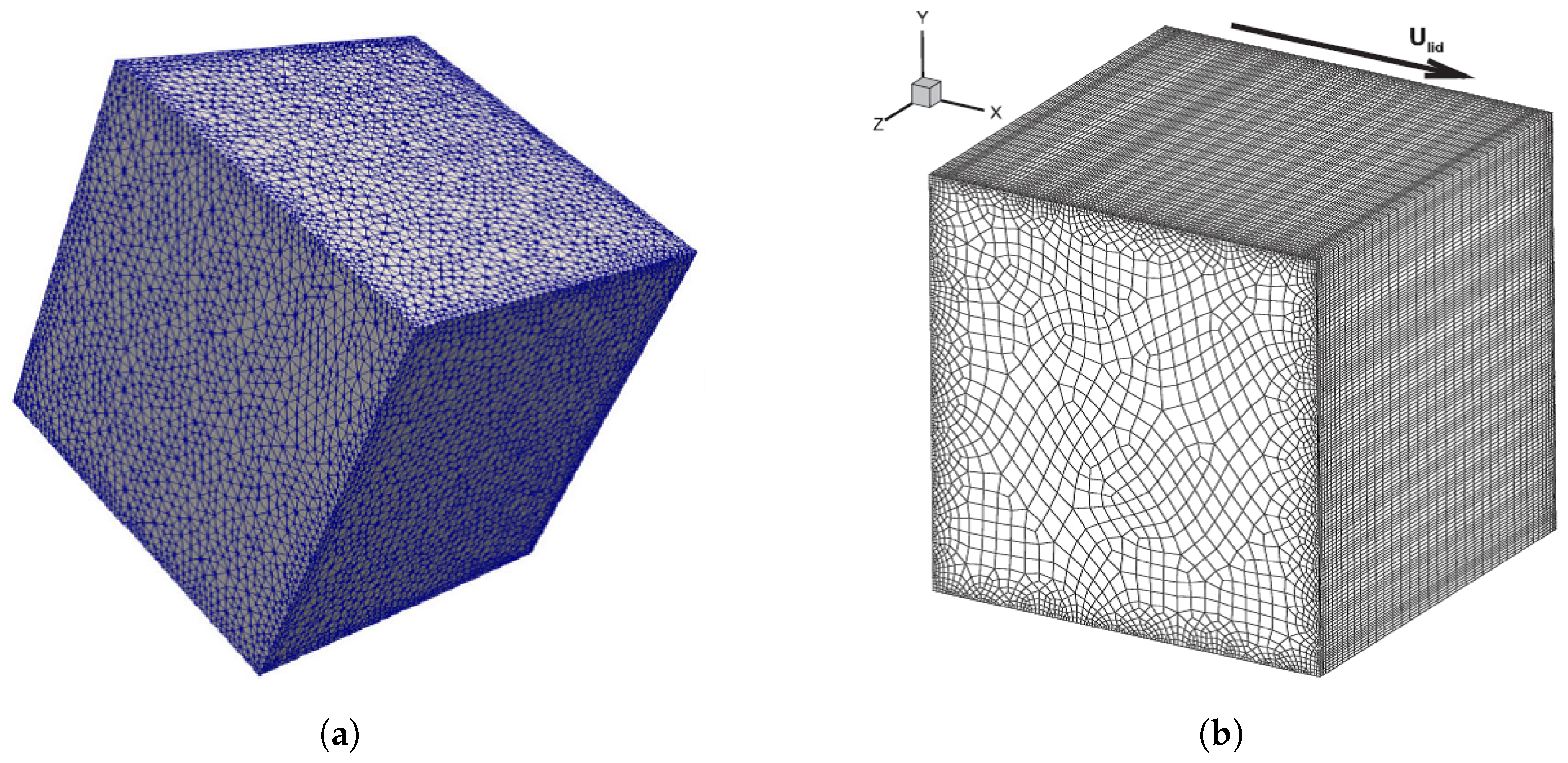
Table 1 it is found that the convergence speed is roughly accelerated up to 15 times and 50 times, respectively, with the same mesh size on the same equipment for the 2D and 3D lid-driven cavity flow. It is worth noting that, as computing devices become more powerful, the acceleration performance will further improve.
Considering the LBM approach, the development appears to have no limits; in fact, various modified LBM models were recently presented. Ilyin [
34] proposed a Gaussian LBM, where the conventional BGK equation was discretized by using a new approach. The linear streaming step and conservation of moments inherited from the original LBM were preserved in the new method, whereas the distribution function was described with a controllable error. Kellnberger et al. [
35] presented a novel LBM for viscoelastic fluids to solve the problem that appears in the simulation of strongly shear-thinning fluids, where the ratio between the high-shear and low-shear viscosities is large, causing numerical stability issues. In general, Fu et al. [
36] focused on the volume-averaged Navier–Stokes equations in multiphase flows and introduced a pressure-based LBM. Different from the original LBM, the pressure was decoupled from density in this method. Two challenges, known as the volume conservation under large pressure gradient and stability across discontinuities in void fraction, were solved. Liu et al. [
37] developed an enthalpy-based LBM for conjugate heat transfer, tackling the problem that the continuity of temperature and heat flux at the conjugate interface is unable to be accurately enforced without special treatment. With this model, the continuity condition for temperature and heat flux on the conjugate interface can be enforced automatically without special treatment. Zhang et al. [
38] presented a volumetric lattice Boltzmann method for modeling and simulating pore-scale diffusion-advection of radioactive isotopes within geopolymer porous structures, in which a concentration field of an isotope seamlessly coupled with the velocity field was introduced and simulated by the evolution of distribution functions. A new method for acoustics simulation in curvilinear coordinates was introduced in Velasco et al. [
39], opening a door to analyze acoustic systems in complex geometries. The assessment of the applicability of LBM on Gen-IV nuclear reactor coolants solidification problems was considered by Freile et al. [
40,
41], and the results were compared with Finite-Volume Computational Fluid Dynamics (FV-CFDs) simulations to validate the LBM and LBM-LES methodologies proposed. The potential of LBM in nuclear reactor subchannel applications was unveiled in the review article from Eugene and Chung [
42], they concluded that LBM is an efficient numerical tool for addressing multifaceted and complex challenges in nuclear reactor applications. Sarmiento et al. [
43] pioneered a Free-Surface LBM-FVM coupling to simulate severe accident scenarios, correlating temperature-dependent viscosity with corium solidification to predict crust formation in debris beds and grid-equipped fuel assemblies. Complementing these efforts, Wang and Ma [
44] unified neutronics/thermal-hydraulics coupling within the lbmNTH framework, integrating FB-LBM (neutron transport), LES-LBM (fluid dynamics), and LBGK (heat transfer) to eliminate cross-physics interpolation while capturing temperature feedback in molten salt reactors. Collectively, these studies establish LBM as a scalable, experimentally validated paradigm for next-generation reactor safety and design—resolving challenges from multiphysics coupling to extreme-condition material behavior through algorithmic innovation and high-fidelity verification.
Furthermore, as the artificial intelligence (AI) is booming nowadays, the development of LBM largely benefits from it. Specifically, the emergence of AI-implemented LBM [
45,
46,
47,
48,
49,
50] is becoming a new trend. Generally, the studies are classified into two kinds, using LBM solutions as dataset [
45,
46,
47,
48] only to train AI models, and improving the numerical performance of the original LBM [
49,
50], both of which accelerate the development of LBM towards a wider range of applications. Considering the improvement of LBM based on AI technology, it generally shows a great computational efficiency and accuracy over the original LBM. In the first place, the numerical stability is enhanced, since AI technologies can predict subgrid-scale turbulence effects more reliably than traditional models, reducing numerical instabilities at high Reynolds number flows. Additionally, the computational accuracy is further improved, due to the fact that physics-informed neural networks (PINNs) learn missing terms in LBM equations from high-fidelity data, improving accuracy in predictions in complex flows. Nevertheless, the acceleration speed is highly increased because AI technologies replace the expensive collision or streaming steps with fast neural network predictions, drastically reducing runtime while preserving physics.
However, despite its potential, AI-supplemented LBM faces several critical challenges: (1) Significant data requirements, training demands large volumes of computationally intensive, high-fidelity simulations or experimental data. (2) Limited generalization capability, models often perform poorly when encountering flow conditions beyond their training scope, such as varying Reynolds numbers or complex geometries. (3) Physical consistency concerns, AI substitution of traditional LBM elements (like collision operators) risks violating fundamental conservation laws. (4) Computational trade-offs, while AI may accelerate certain processes, inference latency from neural networks can negate these benefits. (5) Transparency and reliability issues, the inherent black-box nature of the AI models compromises interpretability and increases vulnerability to input variations. (6) Implementation hurdles, effectively integrating AI with parallel LBM architectures while preserving scalability present substantial technical difficulties. Overcoming these obstacles will require synergistic progress in physics-informed machine learning, adaptive training methodologies, and hybrid computational approaches to achieve robust and efficient fluid simulation solutions.
This literature review reveals that LBM development has primarily emphasized numerical stability, computational accuracy, efficiency and applicability, all strongly dependent on grid structure and associated numerical algorithms. As a result, in the present review study, we will mainly focus on the improvement of grid technologies related to LBM, as well as the corresponding numerical algorithms. The rest of the paper is designed as follows:
Section 2 introduces a brief introduction of LBM foundations,
Section 3 presents the different grid technologies employed and the corresponding algorithms, and the paper ends with the summary of the work presented.
2. Foundations of the Conventional LBM
The Lattice Boltzmann method is a mesoscopic model that connects the microscopic movement of fluid particles and the macroscopic flow properties [
51], which is originated from Lattice Gas Automata (LGA) and then improved into the lattice Boltzmann method by replacing the Lattice Gas Automata with the continuous Boltzmann equation, which is given as follows [
52]:
where
is the distribution function,
defines the space vector,
determines the velocity vector of fluid particles,
is velocity acceleration on each fluid particles, and t is the time. On the right hand side of the equation
is defined as the collision term, which is a complicated integral function.
It is assumed that the flow consists of fluid particles and these particles propagate and collide continuously on a discrete mesh, simulating the macroscopic behavior of fluids. With a further development based on BGK collision theory, the Boltzmann BGK equation can be written as follows:
where
is the BGK collision operator,
is a constant,
represents the discrete equilibrium distribution function, and
defines the discrete distribution function.
Assuming the velocity vector
can be simplified into an N-dimensional limited space
, the velocity discretized single relaxation time Boltzmann equation is written as follows:
where
is the external force term,
define the discrete velocity of fluid particles, and
is the single relaxation time.
When discretizing Equation (
3) on time and space, it produces the single relaxation time discrete lattice Boltzmann BGK equation, as follows:
which is the governing equation for the present study of all simulations. Based on this equation, the propagation and collision process of fluid particles is accomplished, the macroscopic quantities in the fields are then calculated through distribution functions Equation (
5). For instance, taking the incompressible Navier–Stokes equations as the target equation, which can be recovered from the discrete single relaxation time Boltzmann equation [
17,
52,
53,
54,
55], the relevant macroscopic quantities, like density (
) and velocity (
), are calculated through equilibrium distribution functions and given as follows:
Notice that for different target equations, the equilibrium distribution functions are constructed in different forms. Moreover, even for the same target equation, in different LBGK models, the mathematical formulas of equilibrium distribution functions could be different as well. Specifically for the popular LBGK D2Q9 model [
17], the corresponding equilibrium distribution functions for a two-dimensional case are defined as follows:
where
is defined as the weight coefficients, and
represents the lattice sound speed, which is also written in terms of
, where
is the lattice velocity,
is the grid spacing, and
is the time step. The discrete velocities model is presented in
Figure 1.
3. Grid Technologies and Corresponding Algorithms
In the present section, we aim to highlight the importance of the grid considered in any simulation, which represents the discretization of the computational domain, including a real mesh or meshless discrete points. Regardless of the numerical method considered, the essence of any numerical simulation is to employ the appropriate mesh. Generally, the grid discretizes the computational domain in space, based on which, the governing equations can be solved. Regarding the numerical applications, the Navier–Stokes equations are assumed as the target equation, and, in the present study, the most popular single relaxation time LBGK D2Q9 model is chosen to perform the grid technology analysis.
Different from the macroscopic methods, where the grid structures employed are not directly connected with governing equations, the choice of the grid in LBM simulations usually considers the specific discrete lattice velocity model in the first place, especially during the earlier stage of the LBM history. It is reasonable to think that using an appropriate grid, which corresponds to the discrete lattice velocity model, the evolution process (streaming and collision steps) of fluid particles can be more easier and conveniently accomplished.
For example, the discrete lattice velocity LBGK D2Q7 model is presented in
Figure 2a. Indeed, with more advanced numerical models, the grid could theoretically be of any sort; however, the triangular grid presented in
Figure 2b is usually the most appropriate choice for the LBGK D2Q7 model. Because only with the triangular grid, the smooth evolution process is guaranteed exactly on the grid points. Since the LBGK D2Q9 model (
Figure 1) is the most popular model employed in LBM numerical simulations, the corresponding grid is usually chosen as the uniform Cartesian square grid (
Figure 3), which provides a good performance for simple geometries and flows. However, it is important to note that the numerical stability of the LBGK model deteriorates whenever the single relaxation time
approaches 0.5 [
51,
52,
53]. The relation between
and the Reynolds number is given as follows:
where U is the velocity, L is the characteristic length, and Re defines the Reynolds number. As can be seen from the previous equation, as the Reynolds number increases to a large number, the relaxation time approaches 0.5, at which the numerical stability is collapsed. For this reason, in order to simulate the flows at high Reynolds numbers, it is always required to use a very fine grid, having a very small value of
. Additionally, in some cases, the local grid refinement, adjacent to the wall boundaries, is inevitable. Yet, the grid refinement for a uniform Cartesian square grid is not always a smart option, since it will cause a huge computational burden, decreasing the computational efficiency.
The dilemma scientists are trying to resolve consists of that, on the one hand, the uniform Cartesian square grid perfectly fits the nature of the LBGK D2Q9 model, while on the other hand, the grid refinement for the uniform Cartesian square grid is a nightmare for efficient simulations. As a result, the applications of LBM are highly restricted. In order to solve this problem, many efforts have been conducted to enhance the grid technologies and the corresponding algorithms, these efforts will be revealed and discussed in the remaining part of the present section.
3.1. Body-Fitted Grid
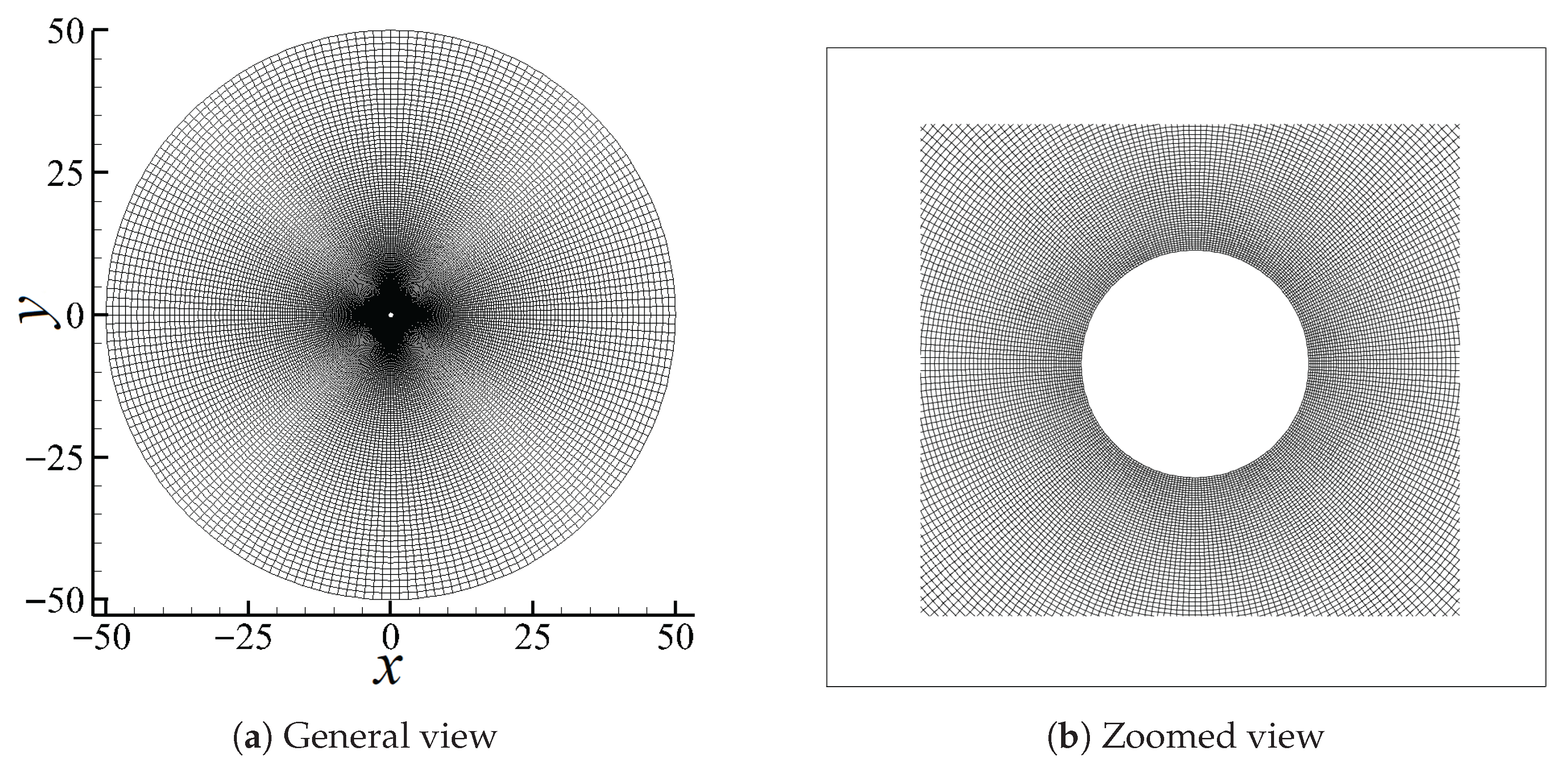
The body-fitted grid, as shown in
Figure 4, is often employed for local grid refinement along the wall boundaries with complex configurations. As a typical representative of structured grid, the body-fitted grid is usually generated through the Elliptic Grid Generation method, solving Poisson/Laplace equations to achieve a smooth grid. Generally, it consists of three steps, discretizing the boundaries, solving the Partial Differential Equations (PDEs) iteratively and adjusting grid spacing parameters to control clustering. However, this can be accomplished based on the Algebraic method, where the boundaries are described by using B-splines or non-uniform rational B-Splines interpolations, and the interior domain is filled through interpolations as well. The mesh density is controlled using stretching functions.
Inspired by the success of the body-fitted grid on the conventional Computational Fluid Dynamics (CFDs), some modified models of LBM were presented, for instance, the Finite Difference Lattice Boltzmann Method (FDLBM) [
57,
58,
59], Interpolation-Supplemented lattice Boltzmann Method (ISLBM) [
60,
61], and the Taylor series expansion and Least square-based lattice Boltzmann Method (TLLBM) [
62]. Some characteristics of these three algorithms are sketched in
Table 2.
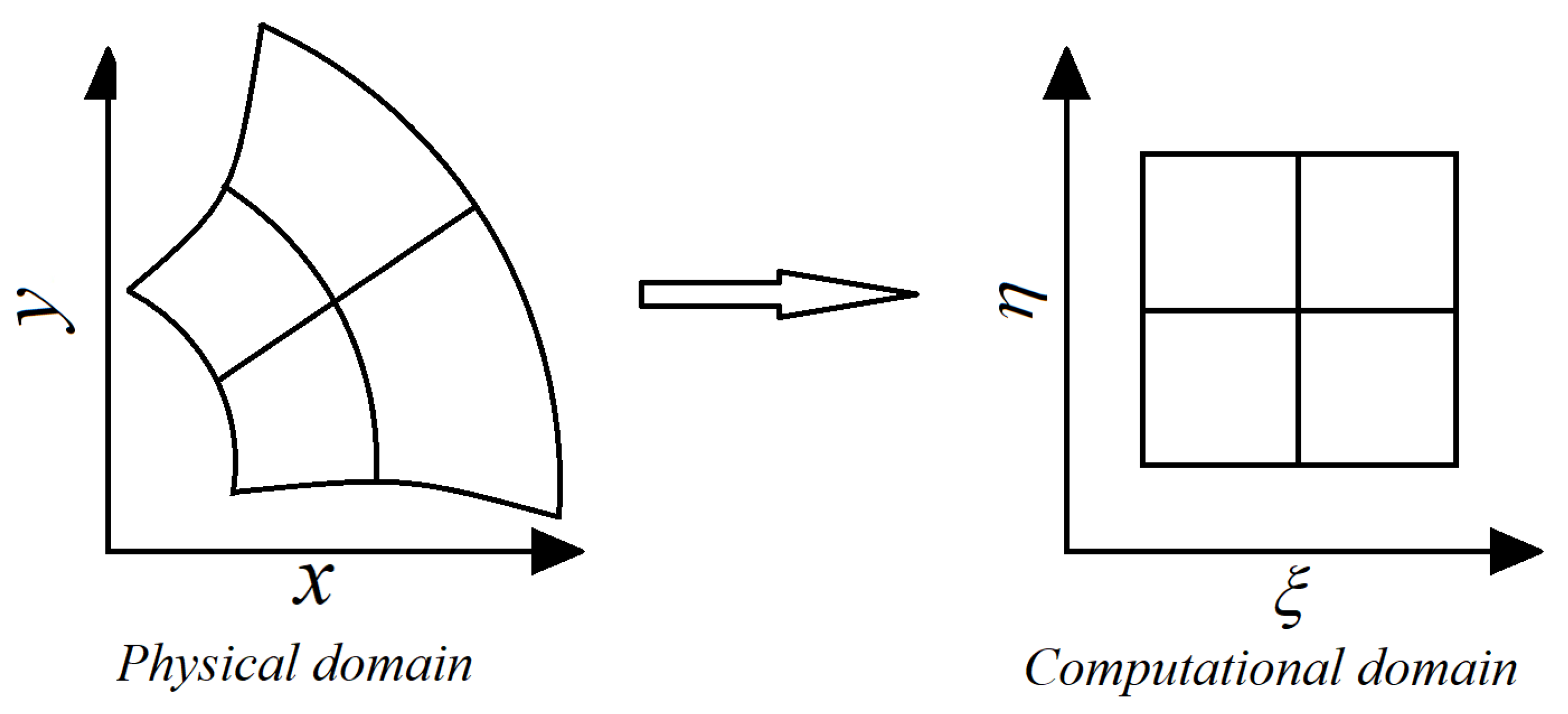
Regarding the FDLBM, it follows the same procedure used in the conventional CFD approach, a coordinate transformation (see
Figure 5) is required in the first place to transform the physical discrete domain (curvilinear system) to a computational domain (Cartesian system) through the Jacobian matrix, given by Equation (
8).
where, the Jacobian is defined as
. Additionally, the partial derivatives of distribution functions with respect to space
in the original evolution (Equation (
3)) are also replaced by
and
. Then, the evolution equation is solved by using numerical difference schemes. For example, the third-order upwind scheme along the horizontal direction x is given as follows:
Although the FDLBM with body-fitted grid is appropriate for local grid refinement, in particular for complex geometries, the computational accuracy, efficiency, and numerical stability highly depend on the choice of the specific difference schemes employed. In addition, in order to maintain the second or higher order of accuracy for the method, the order of accuracy for the selected time discrete scheme should be high enough.
For the ISLBM, the coordinate transformation used in FDLBM is also considered. Yet the difference is that in FDLBM there is no evolution process at all, the governing equation is solved by using finite difference schemes; however, in ISLBM, the evolution process, also known as the streaming and collision steps of fluid particles, is accomplished although not in the physical domain (see
Figure 5), but the transformed computational domain instead (
Figure 5). Since it is assumed that the flow domain can be described by a transformed computational domain
with a one-to-one correspondence in position, where
is a space vector in the physical domain. And considering that the computational domain can be projected onto a uniform Cartesian square grid. The end point of the streaming process is generally no longer a grid node regarding the body-fitted grid, an interpolation is therefore required. According to He and Doolen [
60] the second-order upwind interpolation scheme is given as follows:
where
and
represent the interpolation coefficients, and
and
define the streaming directions. Taking the discrete direction
for a grid node (black dot in
Figure 6); for example. The post-streaming distribution function can be calculated through the interpolation using the neighboring points (red dots in
Figure 6). Notice that all those points can be transformed into the physical domain by using Equation (
8).
Regardless of the successful applications of ISLBM on simulations based on body-fitted grid, it usually brings an extra computation for both coordinate transformation and interpolation at each time step, increasing the computational costs. To the best of our knowledge, the ISLBM indeed developed the LBM applications to the non-uniform irregular grid with a good numerical stability, but the computational efficiency still has room for improvement.
Furthermore, Chew et al. [
62] also introduced a modified LBM for curvilinear systems, the basic purpose is the same as that presented in ISLBM, calculating the post-streaming distribution functions, which are not located exactly on the grid nodes. As described in
Figure 7, the distribution function in the discrete direction
of the grid nodes A, B, C, D, E, and P moves towards the corresponding virtual points A’, B’, C’, D’, E’, and P’, which are not located exactly on the real grid nodes. The core theory of this modified model is that, taking point P; for example, the post-streaming distribution function is not obtained through the interpolations as introduced in ISLBM, instead, by using the neighboring points, a Taylor series expansion and the least square-based approximation is introduced.
3.2. Non-Uniform Rectangular Grid
In order to fulfill the purpose of local grid refinement for LBM simulations, another option of the rectangular grid is considered. The theory of the non-uniform rectangular grid is relatively simple, which is similar to that of the uniform square grid under the Cartesian coordinate system. Unlike the uniform square grid, the grid spacing of the non-uniform rectangular grid is adjustable through controlling the grid spacing parameter. In our previous study [
63], it was accomplished by employing a simple geometric sequence. When employing the grid refinement scale just around the wall boundaries, the total number of cells is reduced by about half when compared with the conventional Cartesian square grid, which to some extent, alleviates the computational burden. As a result, based on the uniform rectangular grid presented in
Figure 8a, a rectangular LBM [
64,
65,
66] was presented. A new rectangular LBGK D2Q9 model was introduced with the discrete velocities sketched in
Figure 8b, where
defines the grid aspect ratio. Consequently, the construction of equilibrium distribution functions are different that of the original LBGK D2Q9 model, based on which, both the multi-relaxation-time LBM [
64] and single relaxation time LBM [
65,
66] models were introduced. Since the grid structure perfectly matches the streaming principle of fluid particles specifically for the rectangular LBGK D2Q9 discrete model, the evolution process is smoothly accomplished.
In reality, the rectangular grid is widely used in a more popular form, also known as the non-uniform rectangular grid, sketched in
Figure 9.
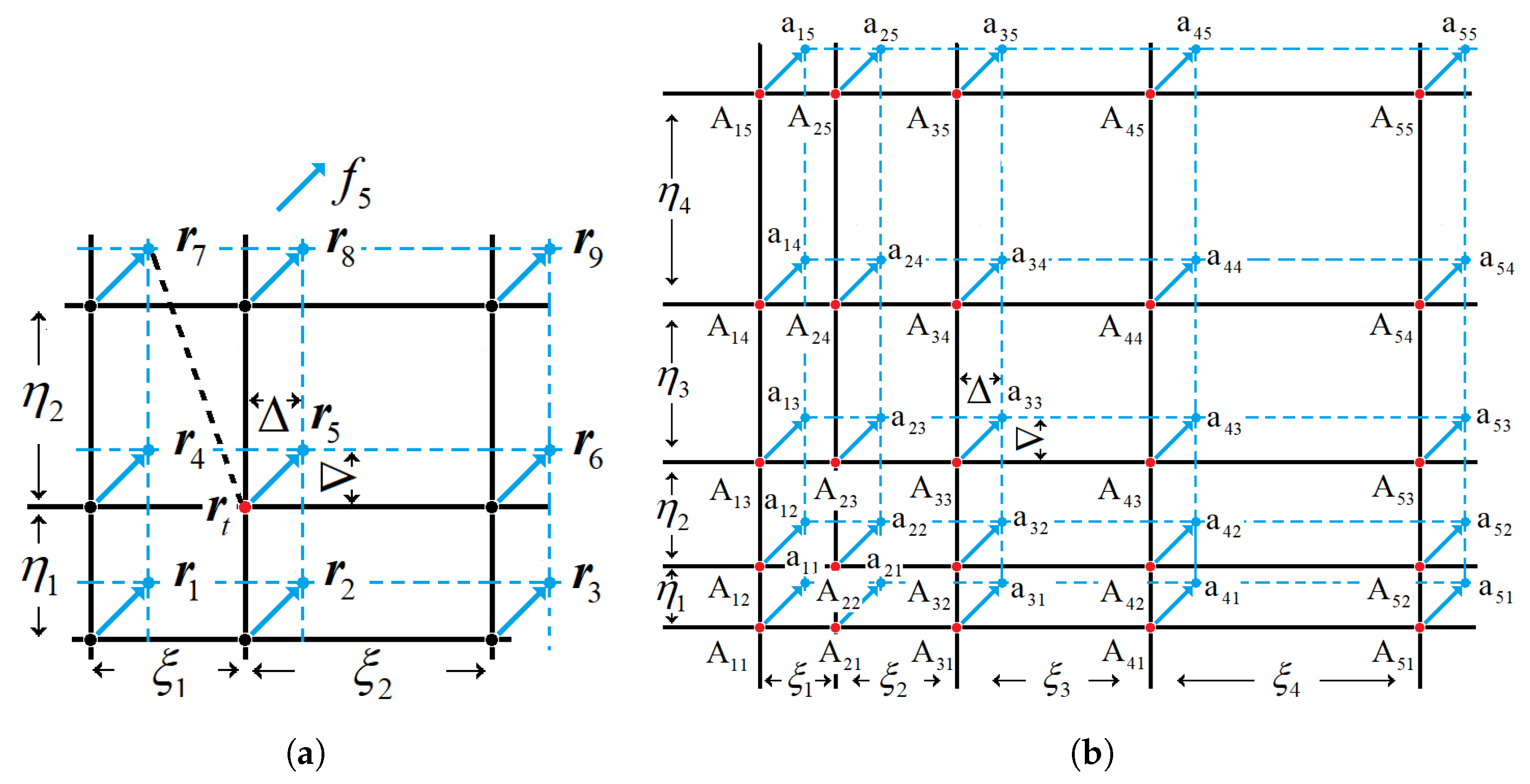
Compared with the uniform rectangular grid, the non-uniform rectangular grid is more flexible for local grid refinement, further reducing the total number of cells. In reality, the present authors introduced a radial basis function implemented LBM (RBF-LBM) and a Lagrangian interpolation-based LBM (LAG-LBM). The discrete velocity model remains the same as that introduced in LBGK D2Q9 (see
Figure 1). Due to the fact that the evolution can not be performed exactly on grid nodes, in other words, the post-streaming distributions remain unknown after each time step, enlightened by the ISLBM, we presented two different interpolations for approximately calculating the post-streaming distribution functions on every grid nodes.
Figure 10 describes the streaming process on the non-uniform rectangular grid along a discrete direction. The interpolation scheme is constructed by using the neighboring point, as shown in
Figure 10a and
Figure 10b, respectively, for RBF 9-bit and Lagrangian 25-bit interpolations. For the RBF-LBM, the interpolation scheme is given as follows:
where
represents the post-streaming distribution functions of the target node
,
defines the interpolation function,
is the general form of radial basis function, also known as the kernel function,
stands for the position of the controlling point, and
characterizes the positions of the surrounding points.
represents the Euclidean distance between two positions,
is given as the coefficient of the
radial basis function and M is the total number of controlling points. The interpolation scheme employed for the LAG-LBM, is given as follows:
where the superscripts
and
, respectively, represent the real grid nodes and virtual nodes,
and
represent the interpolation coefficients.
Regarding the numerical performance of the ISLBM on the non-uniform rectangular grid, the comparison between the RBF interpolation, Lagrangian interpolation, least-square based method and the conventional LBM based on uniform Cartesian square grid is listed in
Table 3. We choose the lid-driven cavity flow at Reynolds number 1000 as a benchmark case.
Notice that the rectangular-based LBM provides a good computational accuracy given a sufficiently small local grid refinement; however, when considering objects with curved boundaries, the grid generation becomes a bit more complicated and time-consuming. In particular, for the RBF-LBM, it remains the second-order of accuracy as the original LBGK, but converges much faster, indicating that the computational efficiency is significantly improved as well.
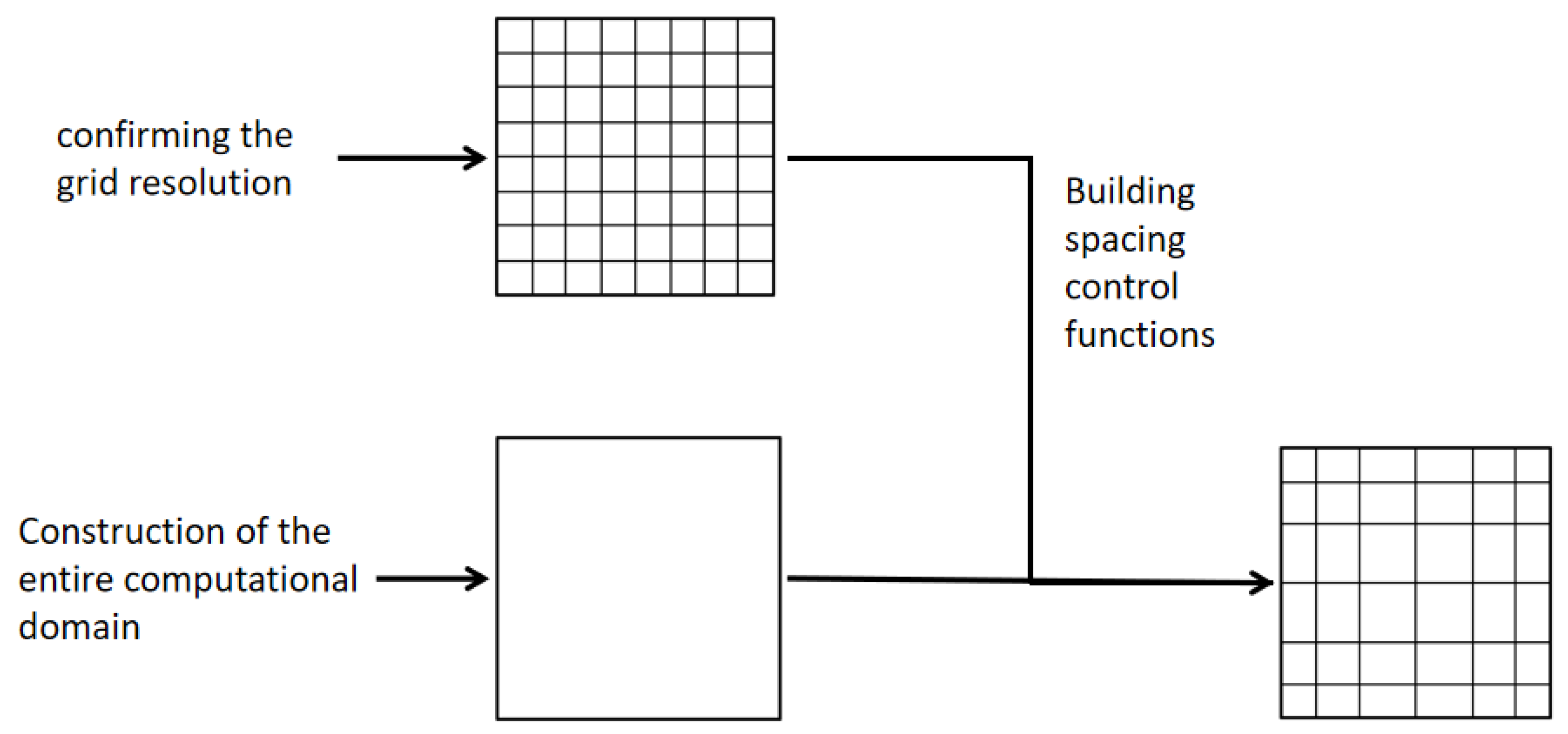
Just to close this section and in order to provide the main steps needed to generate a non-uniform rectangular grid,
Figure 11 is presented. Note that after the construction of the computational domain, the required grid resolution should be obtained. As a third step the spacing control functions, for instance, the geometric sequence, should be built. As a final step, the horizontal and vertical grid points need to be distributed across the computational domain.
3.3. Multigrid Technology
The multi-grid method is a mathematical algorithm for solving linear systems based on multi-grid principles. It is a numerical strategy which accelerates the convergence speed through the iterative operation among several meshes with different resolutions, for instance, the coarse grid, medium grid, and fine grid. The core concept resides in the information transferring process between the coarse and fine grid, in which a coarse grid system of equations is solved initially, and then the solution is transferred to the fine grid through interpolations. Afterwards, the solution on the fine grid transfers back to the coarse grid, closing an iteration loop. The cycle finishes when the convergence is satisfied. This grid technology is suitable for improving the computational efficiency of the original LBGK based on the uniform Cartesian square grid. Actually, it has already been employed in LBM simulations, known as the multigrid LBM [
68,
69,
70,
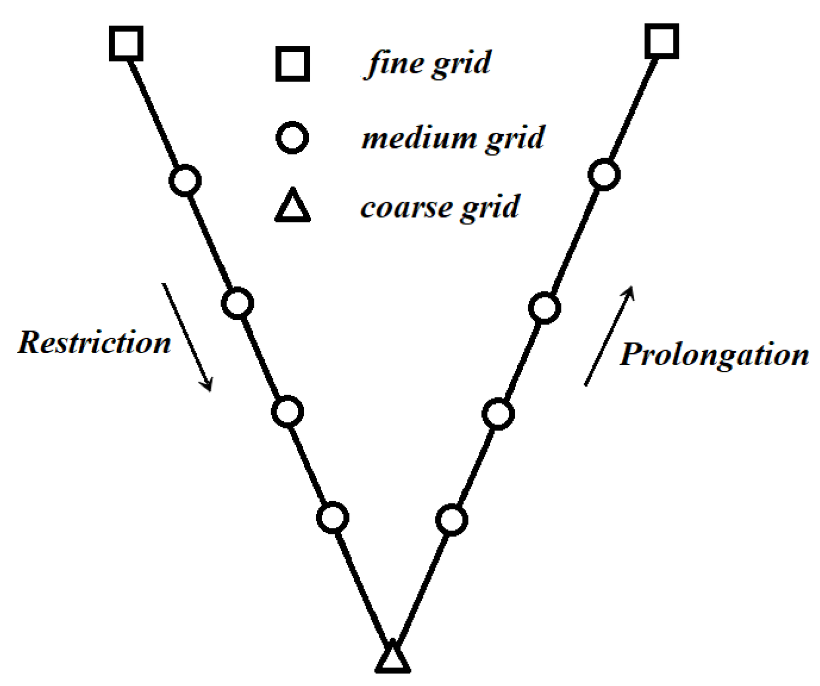
71]. During the past few decades, the multi-grid method has seen great progress, including many specific schemes, for instance, the V-cycle, P-cycle, W-cycle, and F-cycle. Among which, the V-cycle scheme was regarded as the information transferring process from the coarse grid consecutively to the medium grid and the fine grid (prolongation), and then transfers back from the fine grid to medium and coarse grid (restriction). Numerically, the restriction and prolongation operators are, respectively, given by the following two equations.
where
denotes the macroscopic quantities, like velocity
u and density
, on the grid node with coordinates of
,
and
are coordinates on the coarse mesh, and
and
are coordinates on the fine mesh. A full period of the classic V-cycle method is introduced in
Figure 12 and
Figure 13, the information on the fine grid is transferred to medium and then coarse grid through the restriction operator defined by Equation (
13), while the prolongation operation is fulfilled by using Equation (
14) to transfer the information from coarse to medium and then fine grid. This procedure is repeated until a converged solution is obtained.
Indeed, with the usage of the multi-grid technology, the computational efficiency has been improved, even when using a very fine mesh, as long as the multigrid strategy is appropriately employed. The technology works fine with an acceptable accuracy for steady states; however, it fails to predict the unstable solutions with a good accuracy.
3.4. Hierarchical Cartesian Square Grid
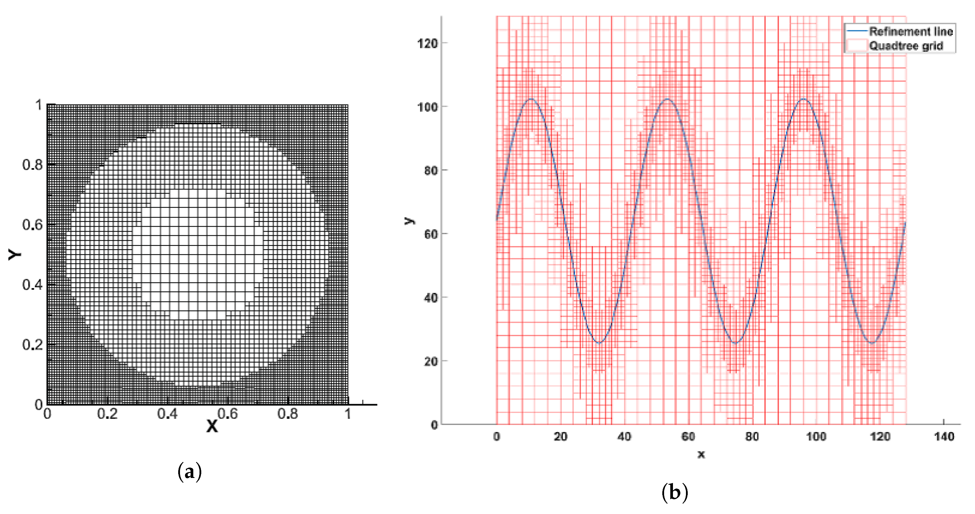
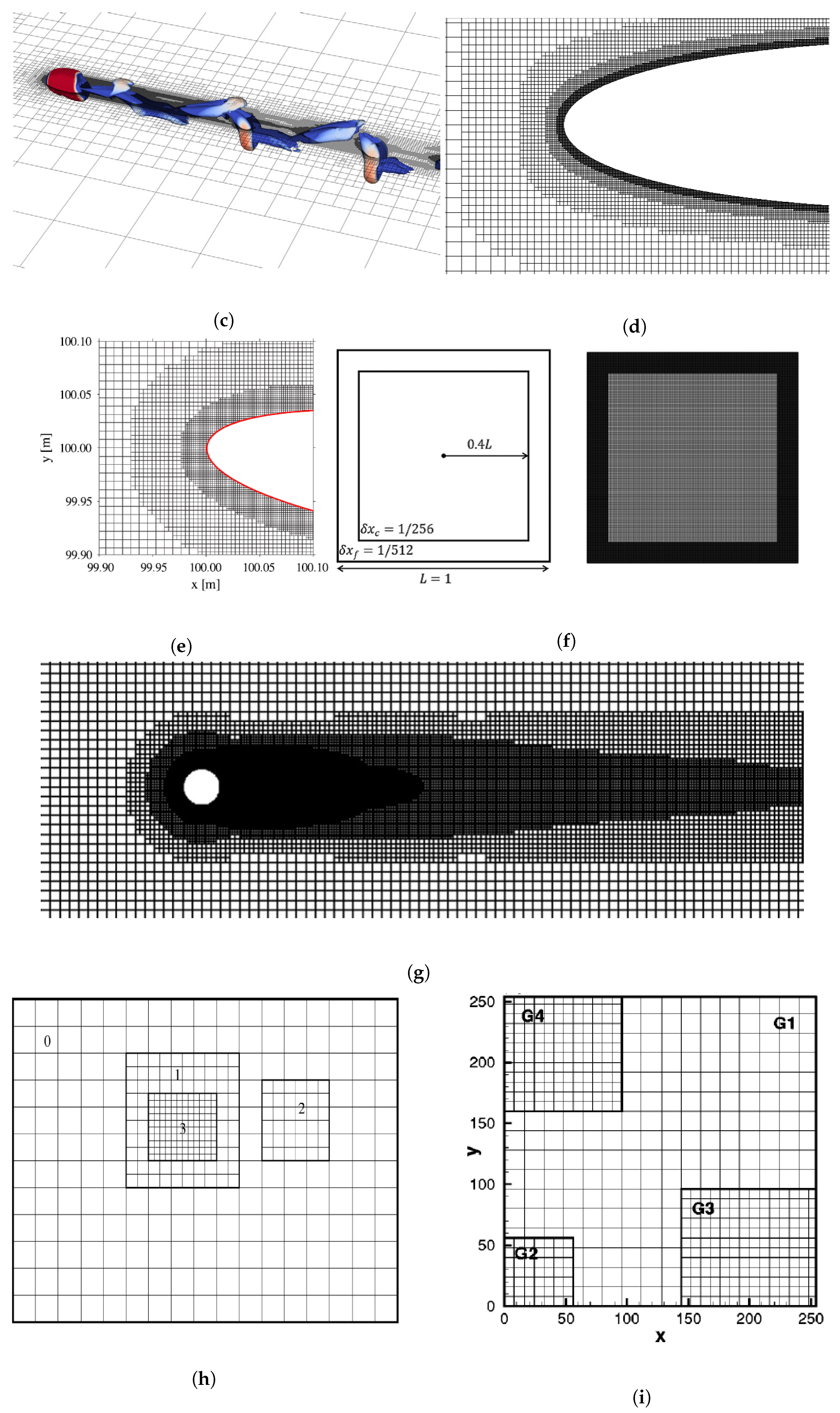
In order to further improve the computational efficiency of LBM based on the Cartesian square grid, apart from the multigrid technology, another efficient strategy for local grid refinement is the hierarchical Cartesian square grid, which was actually named differently in different studies, for instance, quadtree grid [
72,
73,
74], the tree grid [
75], multi-domain grid [
76,
77,
78], multi-resolution grid [
79,
80], hierarchically refined grid [
81], nested grid [
82], and composite grid [
83,
84]. However, the final purpose is consistent, generating the local refined Cartesian grid for LBM simulations, the difference among these studies resides in the specific methods for grid generation and the treatment of the boundary conditions on the overlapping borders between coarse and fine meshes. For instance, the general idea of multi-domain, multi-resolution, nested, and composite grid is roughly the same, dividing the domain into several blocks, each with its own structured grid. Generating a tree grid or hierarchically grid involves recursively subdividing a 2D space into quadrants (or a 3D octree into octants) based on specific criteria (e.g., geometric complexity, solution gradients). Regularly, it includes a few steps, defining the root domain, setting subdivision criteria, performing recursively splitting, adjusting grid density, and generating the entire mesh.
Figure 14 shows that, although different refinement strategies were employed, the grid structure is pretty much similar, serving for the same purpose.
Since the entire computational domain is divided into many sub-domains with different grid levels (grid spacing), the grid consists of the staggered coarse and fine grid. The overlapping borders belong to both, the fine and coarse grid, which is regarded as the interface of information exchange between these two grids and need to be treated specially. This treatment usually requires a spatial interpolation scheme with a high order of accuracy. It is to be noted that the values of grid spacing
for coarse and fine grids are different. A generic mathematical expression relating two grid spacings reads as follows:
which means that during one
time step, the distribution functions evolve twice on the fine grid with grid spacing
, but only once on the coarse grid with grid spacing
. Since it is assumed, in general, that
, which is an enforced condition, we can be certain that the evolution is to be accomplished exactly on the finest grid nodes. As a result, when considering the interpolation along the overlapping borders, it must be performed with the same timing for both coarse and fine grid.
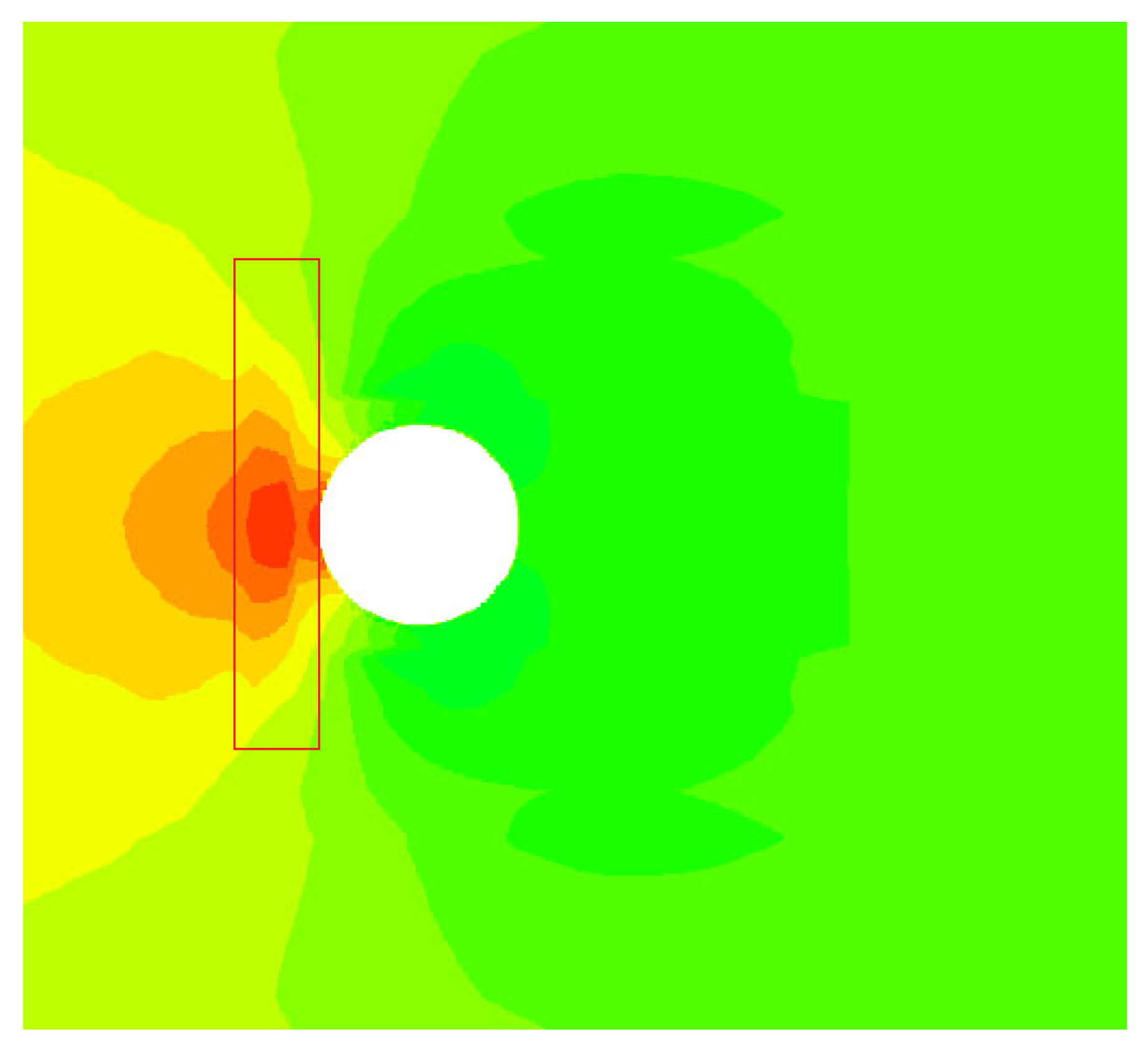
It was evaluated that with the employment of the hierarchical Cartesian square grid, the computational efficiency was highly increased, it was about 20 times faster than that of the original LBM for a given case and using the same equipment, the computational accuracy was excellent. Additionally, the hierarchical Cartesian square grid is applicable for any kind of complex geometries, which makes the LBM applications even more convenient and plausible. However, due to the existence of the overlapping borders, on which the serrations of contours out of the discontinuity are observed, see the marked red box in
Figure 15, the non-uniform Cartesian square grid can be employed in limited applications.
The main concept behind the generation of hierarchical Cartesian square meshes is introduced in
Figure 16. After the computational domain is built, the root cells have to be defined, in parallel to that, the grid levels and the finest grid spacing adjacent to the wall boundaries needs to be determined, the final step consists of generating the sub-grid cells through recursive hierarchical splitting.
3.5. Unstructured Grid
As LBM quickly develops, apart from the efforts to effectively use the Cartesian grid, many scholars have tried to extend the conventional LBM to unstructured grid. Since the structured grid (uniform Cartesian square grid) has a natural limitation for practical engineering applications with complex geometries, in particular a grid refinement adjacent to the wall boundaries [
84]. As a representative of unstructured grid, the generation mechanism of triangular unstructured grids typically follows these key steps: First, the domain boundaries are discretized into segments that will form the initial edges. Then, using either Delaunay triangulation or advancing front technique, interior nodes are created following specified spacing functions. In Delaunay-based methods, points are inserted sequentially while maintaining the empty circumcircle property that ensures well-shaped triangles. The advancing front approach builds triangles progressively by connecting front edges with new nodes or existing vertices, carefully managing front collisions and maintaining proper element sizing. Throughout the process, mesh quality is optimized through edge swapping, node smoothing, and selective refinement to achieve proper angle conditions (typically avoiding angles smaller than 30° or larger than 120°), while conforming to geometric constraints and adapting to solution requirements. Anyway, due to the rapid development and continuous improvement of commercial software, the generation of unstructured meshes has become highly convenient while still ensuring excellent mesh quality. Additionally, in the conventional LBM, the discretizations for moment velocity and space are coupled with each other, which can be clearly seen in
Figure 2 and
Figure 3. But in reality, these discretizatoins do not necessarily have to be coupled [
85]. Hence, a finite volume LBM [
86,
87,
88,
89,
90,
91,
92] based on unstructured grid emerge as a requirement. For this method, the unstructured grid usually consists of triangle or polygon elements, respectively, as shown in
Figure 17a,b.
Among all these studies, Peng et al. [
87] presented a finite volume LBM, which is regarded as the first improved approach in which the grid is really free of structural form [
86]. Based on these excellent studies [
86,
87,
88,
89,
90,
91,
92,
93,
94,
95], the consistent development the finite volume LBM has been performed. Notice that in these studies, the classic LBGK D2Q9 model was usually used for velocity discretization and the space was discretized based on, generally two approaches, the cell-vertex scheme [
86,
87,
88,
89,
90,
91,
92,
93] and the median-dual scheme [
94,
95]. Taking; for example, the cell-vertex scheme with the triangle element, it is observed that the triangular elements surround an interior node (centroid) of the grid, on which the flow variables are arranged, as sketched in
Figure 18. Regarding the construction for the finite volume LBM, no further elaboration will be provided in present study, since the detailed information has already been introduced in the literature [
86,
87,
88,
89,
90,
91,
92,
93,
94,
95]. Notice that with the prosperity of the finite volume LBM, the applicability of LBM simulations was further extended, since the unstructured grid shows a great adaption for complex geometries, especially with curved boundaries. Additionally, the grid refinement can be perfectly performed on the wall boundaries, maintaining the computational efficiency as good as that of the hierarchical Cartesian square grid.
Furthermore, another option known as finite element lattice Boltzmann method [
96,
97,
98], was introduced for unstructured grids, which also increases the flexibility of LBM with an acceptable computational efficiency and accuracy. The core theory is that the governing equation (Equation (
4)) without the external force term
can be split into two separate parts, streaming and collision, and are given as follows:
Due to the fact the collision process is performed locally, there is no need to involve unstructured grid, whereas the streaming must be discretized on an unstructured grid. As a result, the entire evolution is accomplished with two steps, streaming and collision, are calculated separately.
Notice as well that, based on the theory of RBF-LBM [
63] introduced by the present authors, the improved RBF-LBM, can also be applied to the unstructured grid and meshless methods. The main idea is the same as that used in RBF-LBM, suggesting that after the streaming process, the distribution functions (red arrows in
Figure 19) on the grid node (black dots in
Figure 19), stream to the virtual points (red dots in
Figure 19). By calculating the Euclidean distance (red line segments in
Figure 19), the neighboring points needed for the interpolation are allocated. In reality, we choose the nine neighboring points most close to the target grid node P, forming a 9-bit RBF interpolation for approximately predicting the distribution functions.
3.6. Meshless
Following the same idea, consisting in decoupling the velocity and space discretizations, the meshless lattice Boltzmann method [
99,
100,
101,
102,
103] was introduced, see
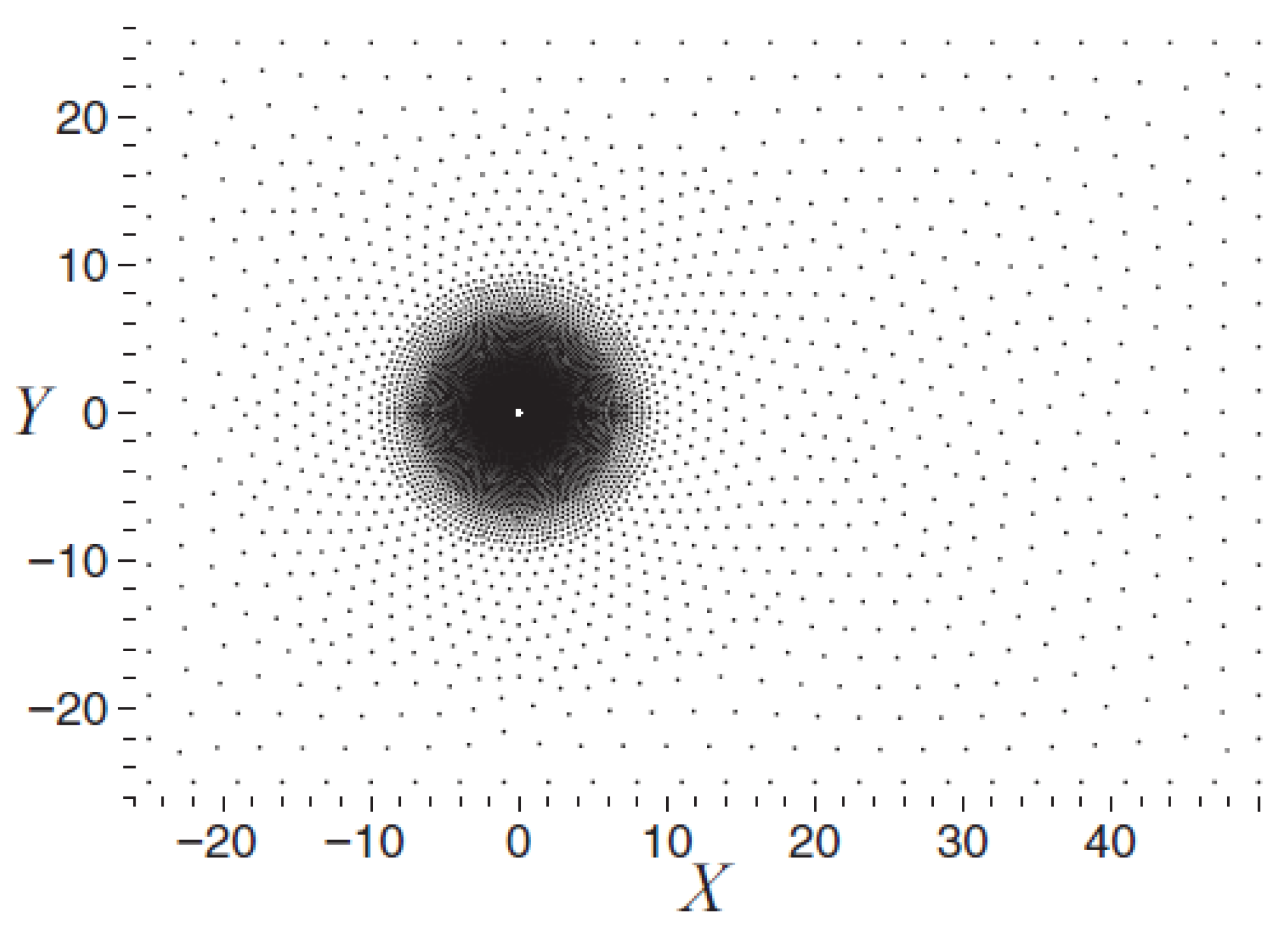
Figure 20. When compared with the unstructured grid LBM, the difference is that instead using a grid, the discrete points are directly employed for simulations. The meshless LBM demonstrates significant advantages in flexibility and adaptability, but computational efficiency and theoretical maturity remain bottlenecks. Its development relies on advancements in meshless methods (e.g., fast neighbor search algorithms) and deep integration with LBM theory. For specific problems (such as fixed, simple geometries), traditional grid-based LBM may be more efficient, whereas for complex dynamic scenarios, meshless LBM holds greater potential. Current applications demonstrate that the meshless LBM has achieved remarkable breakthroughs in complex flow simulations (e.g., blood flow in biological vessels and porous media seepage), dynamic boundary problems (e.g., particle suspensions and fluid–structure interaction), and multi-physics coupling (e.g., heat transfer and chemical reactions).
Traditional LBM enforces evolution through a discrete collision-streaming process, where particle distribution functions (
) propagate along fixed lattice links to neighboring grid points. This strict grid dependency becomes inefficient for domains with curved boundaries or localized phenomena requiring dynamic grid refinement. In contrast, meshless-LBM discards the structured grid entirely. Instead, it solves the Discrete Velocity Boltzmann Equation (DVBE) Equation (
17), on a set of arbitrarily distributed nodes
.
The key innovation lies in replacing the explicit streaming step with spatial derivative approximations computed via meshless methods, such as Moving Least Squares (MLSs), Kernel-based interpolation, and radial basis functions (RBF). By doing so, information propagates implicitly through local node interactions within a defined support radius (h), eliminating the need for grid-aligned connectivity. This enables high adaptability to complex geometries, natural handling of adaptive node refinement/coarsening, and straightforward implementation of deformable/moving boundaries.
While meshless LBM retains the core collision operator (e.g., BGK or MRT) and local conservation properties of conventional LBM, it fundamentally transforms the spatial discretization philosophy. Its flexibility comes with challenges, including computational cost for neighbor search, sensitivity to derivative approximation accuracy, and stability control. Nevertheless, the approach opens new frontiers in LBM applications, including multiphase flows in porous media, fluid–structure interaction, and microscale transport in biomimetic systems.
Notice as well that, in the meshless LBM, although the traditional explicit mesh does not exist, the grid nodes distribution is essential, which is controlled and accomplished by using methods like, random point generation, Poisson disk sampling, background grid-based method, and geometry-adaptive technology. The main challenge resides in efficient calculation of distribution functions and dealing with evolution process of fluid particles under the meshless condition.
Based on Taylor series expansion and least square method, Shu et al. [
99] presented a modified LBM which according to the authors, shows a remarkable computational efficiency. The basic theory is the same as the one introduced in their investigation [
62] in
Section 3.1, suggesting that the post-streaming distribution functions which do not exactly fit on the grid nodes are approximately obtained through Taylor series expansion combined with the least square method. Based on the RBF interpolation, Strzelczyk and Matyka [
100] also introduced a meshless LBM to simulate the evolution equation on the discrete points. The basic idea is exactly the same as that introduced by the present authors when dealing with the non-uniform rectangular grid and unstructured grid. It was concluded that the meshless LBM based on RBF has a better performance on complex geometries [
95,
96,
97,
98,
99,
100]. Bardow et al. [
101], introduced a multispeed meshless LBM, in which the discrete velocities were obtained from minimization of the entropy function H with mass and momentum conservation applied. Since the meshless lattice Boltzmann methods are not restricted to rational number ratios between discrete velocities, the exact Hermite models along with their rational-number approximations can be directly used in the design of the meshless LBM. It was proved that the computational accuracy was improved by using the multispeed model. The method presented by Musavi and Ashrafizaadeh [
102,
103] is regarded as the simplification of the finite element LBM, where the evolution equation was solved separately with two steps, streaming and collision. The space was discretized by using local Petrov–Galerkin scheme and the time was discretized by using the Lax–Wendroff scheme. Obviously, the meshless LBM further increases the flexibility of LBM, whereas the numerical procedure is relatively a bit simpler than that of the unstructured grid LBM.
4. Summary
In this paper, a review on the grid technologies and the corresponding algorithms under the framework of lattice Boltzmann method is presented. In order to improve the numerical accuracy, efficiency, stability and flexibility, different grid strategies along with the modified approaches are proposed.
Table 4 lists a systematic comparison of the different grid technologies under the framework of LBM. Notice that since many numerical simulations involve different benchmark cases, computational conditions, and grid configurations, it is difficult to conduct quantitative discussions. Therefore, we can only provide qualitative conclusions regarding certain aspects of the numerical performance. The first row introduces the specific grid technologies included in the present paper.
The second row focuses on the applicability of each grid technology with considering its corresponding numerical methods, where S stands for steady solutions and U represents unsteady solutions. It is concluded that the multigrid technology fails to deal with the unsteady solutions. The other grid technologies can handle both steady and unsteady problems. However, the use of body-fitted grid requires the introduction of interpolation or coordinate transformations, which may increase numerical dissipation and affect the high-frequency characteristics of unsteady flows. With the use of the non-uniform rectangular grid and in order to improve computational accuracy, for square velocity discretization models considering high-order accuracy interpolation schemes, for instance, 16-bit Lagrangian interpolation or 16-bit radial basis function interpolation, must be employed. For rectangular velocity discretization models, the construction of the equilibrium distribution function must satisfy both Galilean invariance and isotropy. Considering the hierarchical Cartesian square grid, a high-order accuracy interpolation scheme is required on the border of coarse and fine mesh, to avoid high-frequency flow distortion. Moreover, the grid scale transition from coarse to fine must be smooth to alleviate the isotropy disruption of LBM on the overlapping borders. Regarding the unstructured grid, the mesh quality should be high enough, to avoid mesh distortion and excessive variation in element scales. For meshless points, the discrete points on the surface must be sufficiently dense to accurately describe the geometric characteristics, while higher-order interpolation schemes should be employed to ensure precise estimation of the distribution functions. Additionally, appropriate kernel functions must be selected to fulfill boundary condition treatment.
The third row characterizes the numerical stability of each grid technology. It is found that for the body-fitted grid, the numerical stability highly depends on the mesh quality. Mesh distortion and excessive scale differences accelerate numerical dissipation and induce instability. The situation is roughly the same for the non-uniform rectangular grid, multigrid LBM, and hierarchical Cartesian square grid. The numerical stability solely depends on the interpolation scheme (streaming supplementary), information transfer scheme between coarse and fine mesh, and virtual boundary condition treatment (overlapping borders of coarse and fine mesh), respectively. Regarding the unstructured grid, the numerical stability is highly sensitive to mesh quality, while also demanding interpolation schemes with high-order of accuracy, otherwise, severe numerical dissipation may arise. The numerical stability of meshless points is significantly influenced by the distribution of the discrete points.
The grid flexibility is discussed in the subsequent row, where the use of meshless points is technically feasible for any kind of geometries including complex configurations, and the unstructured grid performs second best. They are followed by the hierarchical Cartesian square grid and the non-uniform rectangular grid, which can be applied to the complex geometries with moderate curvature. The body-fitted grid demonstrates comparable performance for complex geometries with smooth curvature variations, while the multigrid LBM is mostly used for simple geometries. For the purpose of grid refinement, considering the change in the total number of cells, the hierarchical Cartesian square grid is undoubtedly the best performer, compared to a structured rectangular grid, the number of total cells is reduced by 95% on average, and can be further improved considering better grid strategies. With the use of the body-fitted grid or the unstructured grid, this figure roughly reaches 80%, still having a satisfactory grid reduction. Considering the non-uniform rectangular grid, the cell reduction versus the uniform rectangular mesh is at least of 50%, which can be further improved by using non-uniform rectangular grid with grid spacing adjustable.
With the use of different grid technologies introduced and combined with the corresponding algorithms, the convergence acceleration ratio increases for all situations except for the body-fitted grid. Convergence acceleration ratio is defined as , where is the computational time needed to obtain a converged solution using the chosen grid technology, while is the corresponding time when considering the conventional LBM and when using a uniform square grid. This is because, whether using FDLBM, ISLBM, or FLLBM, the additional computational overhead is inevitably introduced. Operations such as coordinate transformations, interpolation transfers, and matrix calculations significantly increase computational time. Overall, although the total number of cells is substantially reduced compared to a uniform Cartesian grid, the computational efficiency is also diminished, this problem becomes even more pronounced when simulating unsteady flows. In contrast, hierarchical Cartesian square grid LBM and multigrid LBM can significantly improve computational efficiency while reducing the total number of grid cells, whereas the non-uniform rectangular grid, unstructured grid and meshless points can improve the computational efficiency to some extent, roughly increasing the convergence acceleration ratio by 3 times. But this highly depends on the specific simulations, including grid quality, total number of cells, coarse/fine mesh distribution, equipment status, interpolation schemes, governing equation solvers and the numerical case.
In order to qualitatively discuss the accuracy of different grid technologies combined with the corresponding algorithms, the present authors performed some simple tests. For the body-fitted grid, we choose the flow over a circular cylinder, the grid resolution being 256 × 256 and the far-field boundary was set at 30 times the cylinder radius, FDLBM and ISLBM were employed. A steady Reynolds number 40 and an unsteady Reynolds number 100 were chosen for comparison. The drag coefficient main relative error values were roughly of 0.5% and 1.86%, respectively.
For the rest of the grid technologies, a classic 2D lid-driven cavity flow was chosen. Two Reynolds numbers 100 and 8800 were chosen for steady solution and periodic orbit. For the non-uniform rectangular grid combined RBF interpolations and considering a grid resolution of 128 × 128, which produced a minimum grid spacing of 1/2048, the relative errors fell below
and
for the steady and unsteady cases, respectively. Regarding the multigrid technology, the grid level was set as 5 with the finest grid resolution of 800 × 800. Considering the hierarchical Cartesian square grid, the total number of cells was 1,568,332 with the smallest grid spacing 1/600. For the case of the unstructured gird combined with FVLBM, the total number of cells was 100,944 with a smallest grid spacing of 0.0016. The total points of the meshless method combined with RBF interpolation was 18,352. The mean values of the relative error on the velocity component
at the cavity center are listed in the last row of
Table 4, from where it is seen that for the unsteady cases these errors are about twice the ones obtained for unsteady conditions. Notice that the discussion on computational accuracy in this paper does not fully represent the intrinsic characteristics of the meshing and algorithms themselves. Rather, it qualitatively demonstrates the general performance of each grid structure and corresponding algorithm in terms of accuracy compared to uniform Cartesian grids, based on specific test cases. In reality, numerical simulation accuracy is influenced by numerous factors, making quantitative comparisons challenging due to fundamental differences in solution methodologies.
Anyhow, all these methods are recognized as reliable numerical approaches for simulations with engineering purposes, as long as the chosen method is appropriate to the given problem.
With the fast development of LBM during the last few decades, it seems that the improvement on novelty of new approaches nearly reaches a limit. But, nowadays, as the technology of artificial intelligence is booming, a great breakthrough in LBM for the next ten years could possibly happen in the research of AI supplemented LBM. Nevertheless, researchers need to be mindful of the potential drawbacks and carefully consider the trade-offs between computational cost, accuracy, and physical interpretability when choosing and implementing these techniques.


