1. Introduction
Two-phase flow, central to many engineering applications, involves the interaction of immiscible fluids (e.g., liquid and gas) separated by an interface. Across this interface, physical properties like density and viscosity may vary abruptly, introducing challenges such as discontinuities in velocity and pressure fields, surface tension effects, and spurious currents. Accurately modeling these phenomena is crucial for simulating processes such as droplet coalescence and capillary flows realistically. Accurate simulation of these phenomena requires solving complex Partial Differential Equations (PDEs), often in intricate geometries. While standard FEM performs well in single-phase problems, it struggles with two-phase flows due to its reliance on body-fitted meshes, which require remeshing as interfaces move. It also lacks built-in mechanisms to accurately handle discontinuities across interfaces, limiting stability and accuracy without additional modifications.
Two-phase flow simulations require accurate and effective interface tracking between the phases. Interface-capturing methods, such as the level-set method, excel at this by implicitly representing the interface, making them effective tools for simulating complex two-phase flow phenomena. See, for example [
1,
2]. The level-set method handles two-phase flow by implicitly representing the interface as the zero level set of an auxiliary function, typically a signed distance function, defined on a fixed grid. This implicit representation facilitates the simulation of complex interfacial phenomena, including merging and breakup, without requiring frequent mesh updates. However, this implicit representation can lead to significant discontinuities in material properties within elements intersected by the interface, potentially affecting the accuracy of the simulation.
On the other hand, standard FEM, relying on smooth polynomial shape functions, struggles to accurately represent the sharp gradients in material properties across the interface. This limitation often leads to inaccurate stress or strain predictions near the interface, necessitating specialized techniques for improved fidelity. To overcome this challenge, common approaches include smoothing material properties across the interface within the cut elements and approximating the surface tension force as a body force distributed over a narrow band around the interface. This approach, known as the Continuum Surface Force (CSF) method [
3], is inspired by techniques used in finite difference and finite volume methods. Similar approaches for handling surface tension are employed in finite difference and finite volume methods; see, for example [
4].
The extended finite element method (XFEM), initially proposed for crack propagation problems, offers an alternative approach. XFEM enriches the standard finite element shape functions to represent arbitrary discontinuities within elements explicitly. This versatile method has been successfully applied to various problems, including fluid–structure interaction, premixed combustion, and two-phase flow (see, e.g., [
5,
6,
7]). In two-phase flow, the velocity field typically exhibits kinks across the interface due to the differing fluid properties. However, the pressure field can exhibit more complex behavior. Pressure jumps and discontinuities in the pressure gradient may occur at the interface, significantly influencing the fluid flow dynamics. To improve accuracy, XFEM enhances standard FEM by using special enrichment functions (kink enrichments for velocity and jump enrichments for pressure) to better capture the expected discontinuities in two-phase flow (e.g., [
8]). In contrast, some studies (e.g., [
9,
10]) applied enrichment only to the pressure field, without incorporating kink enrichments for velocity.
Building on XFEM, the Cut Finite Element Method (CutFEM) further refines this approach by directly addressing the challenges posed by the cut elements. Unlike standard FEM approaches that rely on body-fitted meshes aligned with the interface, CutFEM does not require the finite element mesh to align with the interface, providing greater flexibility in mesh generation; see [
11]. By incorporating stabilization techniques, such as Nitsche’s method and Ghost Penalty (GP) methods, CutFEM provides a robust framework for handling the complexities arising from the interface intersections.
This study employs a Nitsche-type extended variational multiscale method for two-phase flow. The effectiveness of the Nitsche method has been extensively studied and validated across various fields of computational mechanics and applied mathematics. Fundamental theoretical insights into penalty methods and their application to boundary value problems were provided in [
12,
13]. Subsequent research has extended the method to handle more complex boundary conditions and non-matching grids, enhancing its versatility and applicability. For further details, refer to [
14].
Building upon the Nitsche method, the Ghost Penalty (GP) method was developed to address challenges associated with cut or embedded finite element meshes. This technique enhances stability by introducing additional penalty terms that improve the conditioning of the solution, particularly for small or irregularly shaped elements. The concept of face-oriented ghost penalty terms was first introduced in [
15] and later adapted for the Stokes problem in [
16]. These terms play a crucial role in regulating the enriched solution values, thereby ensuring stability of the numerical scheme and achieving optimal error convergence. An example of employing a GP-stabilized Nitsche method for two-phase flow governed by the stationary Stokes equations can be found in [
17].
The main focus of this article revolves around developing a formulation for two-phase flow, where we operate under the assumption of continuous velocity distribution throughout the domain, while acknowledging a discontinuous pressure distribution across interfaces. This formulation draws inspiration from the research conducted by Schott and Wall [
18,
19,
20], which pioneered the development of a stable extended finite-element-based computational approach. Initially designed for simulating single-phase flows governed by the nonlinear incompressible Navier–Stokes equations, their approach was later extended to multiphase flow. It incorporates a Nitsche-type method to weakly enforce boundary conditions and employs CIP stabilizations to tackle instabilities within the fluid domain, as outlined by Burman et al. [
21]. To address issues caused by poorly intersected finite elements and to stabilize fluid velocity and pressure near boundaries, GP stabilization, introduced by Burman and Hansbo [
16], has been extended to the incompressible Navier–Stokes equations.
Research conducted by Massing et al. [
22] has demonstrated that the formulation maintains inf-sup stability. This stability has allowed for the establishment of optimal a priori error estimates in an energy norm for a linearized auxiliary problem governed by the Oseen equations, as detailed in the same work by Massing et al. Building on this foundation, Schott [
20] extended the method to address multiphase flow scenarios. We aim to further develop this approach for cases where the velocity field remains continuous, but the pressure exhibits discontinuities across interfaces. In such problems, the interface between the two fluids acts as a discontinuity surface for the pressure field due to the presence of capillary forces, while the velocity remains continuous to satisfy the incompressibility condition and the no-slip interfacial coupling. This modeling assumption is commonly used in incompressible multiphase flow and is further justified in
Section 3, where we discuss its physical motivation and numerical advantages.
In the numerical solution of the nonlinear, implicit, time-dependent Navier–Stokes equations, each time step involves solving a linear system corresponding to the Oseen problem studied in this paper. Depending on the chosen linearization strategy, the convective velocity is either evaluated using the solution from the previous time step (semi-implicit scheme) or updated iteratively using the current approximation in a fully nonlinear approach. To stabilize the resulting saddle-point problem, we introduce CIP/GP terms, as will be detailed in Theorem 1. While these stabilization terms are effective, they can potentially affect the accuracy of the solution. However, Theorem 2 will establish that the method remains consistent and that the convergence rates of the finite element method are preserved.
In addition to the theoretical advancements outlined above, we aim to validate this formulation through numerical experimentation and investigate its convergence behavior. To achieve this, we implement all the presented methods using the Finite-Element Multi-Grid library FEMuS, developed at the Department of Mathematics and Statistics of Texas Tech University.
The novelty of this work lies in applying a unified CIP/GP stabilization within a CutFEM framework, tailored for multiphase problems with pressure discontinuities, and implemented without enrichment functions. Unlike prior XFEM-based or linear-only formulations [
20,
22], our method supports nonlinear multiphase flows with higher physical fidelity and is validated through convergence studies and standard multiphase benchmarks.
2. Two-Phase Flow
We consider two-phase flow within the domain
, where
d denotes the spatial dimension of the problem. The time-dependent moving phase interface
divides the domain
into two disjoint subdomains
and
, that is
, representing the two phases. For the boundary of the subdomain
, we define the Dirichlet and Neumann boundary parts of the fluid domain as
and
, respectively. We assume that
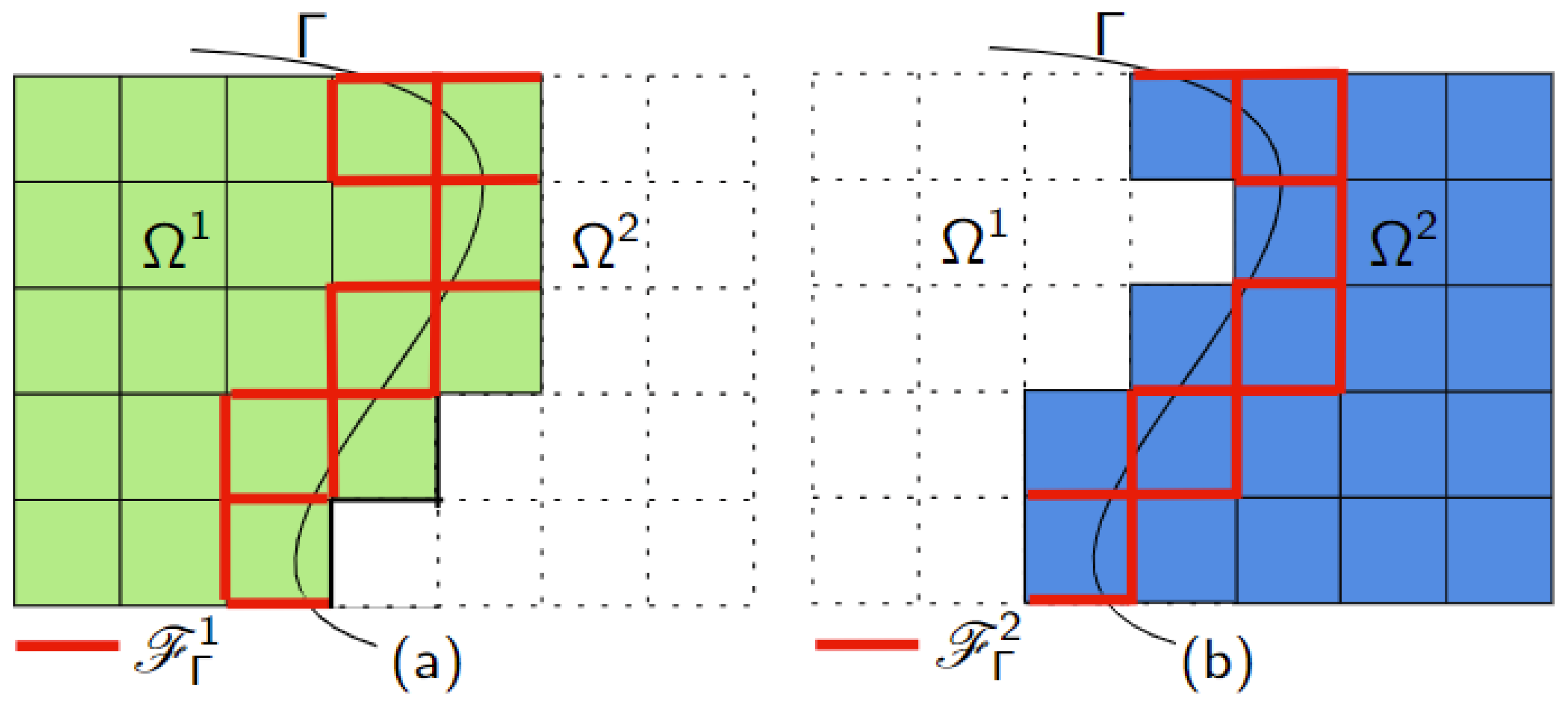
(see
Figure 1). The unit normal vector
n on the interface
is defined as pointing toward the subdomain
. For each subdomain
, where
, we denote by
the unit normal vector pointing outward from
. On the interface
, this implies that
. Assuming the phases are immiscible, the flow in both subdomains
and
is governed by the Navier–Stokes equations
where
and
are the density and dynamic viscosity of the corresponding fluid, and are considered constant within each phase. Furthermore,
is the velocity and
the pressure in the domain
,
is the rate of deformation tensor, and
is the body force, where
g is the gravity acceleration vector.
Appropriate initial conditions are prescribed in
, along with boundary conditions on the external portion of
, which lies on the boundary of the overall domain
, following standard practice. At time
, a divergence free velocity field
is prescribed:
Dirichlet and Neumann boundary conditions on
and
, respectively, are given as
where
denotes the Cauchy-stress tensor, where
denotes the
identity matrix.
In our study, we consider a scenario where the velocity field is continuous across the interface, while the pressure field is allowed to be discontinuous. Specifically, we enforce the condition that the jump in velocity across the interface is zero, denoted as
where
denotes the jump operator across the interface
. This ensures that the fluid flow does not exhibit any discontinuities at the interface.
Furthermore, we consider the jump in the stress tensor across the interface. The stress tensor
, which depends on the velocity
u and pressure
p, experiences a discontinuity that is balanced by the surface tension effects. Mathematically, this is represented by
where
is the surface-tension coefficient, and
is the curvature of the interface. This condition ensures that the difference in the normal stress across the interface is balanced by the surface tension force, which is proportional to the curvature of the interface.
3. Variational Multiscale Formulation for One Phase
The functional space for admissible fluid velocities is . The corresponding space of admissible test functions, , is defined to have a vanishing trace on . For the pressure field, the trial and test function space is set as when , and as when . The resulting variational formulation for the incompressible flow problem is given below.
For all
, find fluid velocity and pressure
, such that for all
Here,
,
, and
denote the usual
inner products in
,
and
, respectively.
3.1. Computational Domains and Meshes
The finite-dimensional space is constructed by defining the computational domain and generating a mesh as follows. Let
be a background mesh with mesh size defined by a positive, piecewise constant function
h over each element, covering an open and bounded physical domain
. The faces intersected by the interface
are integrated across their entire surface area. We refer to
as the set of elements that contain a part of the interface
.
We also define the set
within subdomain
, that consists of all mesh elements
T from the background mesh
such that the intersection of the element
T with the subdomain
is non-empty. This active portion of the mesh includes all faces
F in the interface zone, where at least one adjacent element intersects the interface.
See
Figure 2 for a graphical representation of
and
. For notational convenience, we denote the union of all active elements
by
, representing the active part of the computational domain as a continuous region.
3.2. Continuous Interior Penalty (CIP) Stabilization Method
The core concept of the CIP method involves enhancing the discrete variational form by incorporating a stabilization term (see [
23]). In the context of the Navier–Stokes equation, CIP introduces specific terms to address instabilities and enhance numerical stability. These additional terms are crucial in mitigating errors and ensuring accurate simulations of fluid flow phenomena. Distinct sets of CIP terms are applied to the Navier–Stokes equation for the domains
and
. The CIP terms for the Navier–Stokes equation are as follows:
Let
and let
be the advective velocity field. Then, the (weakly) consistent symmetric jump-penalty stabilization operators in (
9) are defined as
with non-dimensional stabilization parameters
and element-wise scaling functions
and according to face averages
at the interior faces
, where
is the set of interior faces shared by exactly two elements, denoted as
and
, in the mesh
.
The penalty parameters used in the Nitsche, CIP, and ghost penalty stabilization terms play a crucial role in ensuring the consistency, coercivity, and numerical stability of the formulation. Following guidelines from prior work (e.g., [
24,
25,
26,
27]), we adopt the following scaling strategy. For the CIP stabilization, we set
for hexahedral and wedge elements, and
for tetrahedral elements, as suggested in [
28]. The velocity stabilization parameter is set as
, consistent with the recommendations in [
21]. Convective and reactive stabilization scaling factors are chosen as
and
, respectively, based on the analysis in [
28,
29].
Note that we denote the mesh size function by h, defined over the entire computational domain. The function h is piecewise constant, and it takes a constant value on each mesh element T. This value, denoted by , represents a characteristic length of the element.
CIP-based discrete variational multiscale formulation for each subdomain is thus obtained by introducing CIP terms (
9) in the projected variational form (
8), where we seek the velocity and pressure pair
such that for all
,
3.3. Coupled Variational Multiscale Formulation
Beginning with Equation (
10), the first step towards a coupled variational formulation for two-phase flow is achieved by summing the individual phase formulations. Using the jump operator and the unit normal vector, the interface terms on the left-hand side can be expressed as follows:
where we used the following weighted average operators
with positive weights
and
, such that
. In this work, we utilize the coupling condition for fluxes,
on
.
Nitsche’s method is employed to weakly enforce interface coupling constraints. For a comprehensive understanding of this method, readers are referred to [
12,
13,
14,
30]. The core principle of Nitsche’s method for viscous-dominated problems involves the addition of terms related to viscous and pressure adjoint consistency, analogous to the existing viscous and pressure consistency terms
The corresponding penalty Nitsche-type terms are
where
and
denote the penalty parameter and stabilization scaling for different flow regimes, respectively. Note, the weights in (
11) for
,
are defined as
and
, where
, and
is a scaling factor derived from a weakened trace inequality. In the simplest case, this scaling satisfies
.
3.4. Face-Oriented Interface Zone Fluid Stabilizations
To ensure proper stabilization of the two-phase flow formulation and achieve optimal error convergence, face-oriented ghost penalty stabilization terms are applied specifically in the interface zone. These terms are strategically integrated in regions where significant interfacial interactions occur, as shown in
Figure 3. Additionally, distinct ghost penalty terms are employed for the two separate domains, tailored to effectively address the unique characteristics and challenges encountered within each domain. By incorporating these carefully designed stabilization techniques, the computational model achieves enhanced accuracy and stability, which is crucial for the reliable simulation of complex fluid dynamics phenomena in two-phase flows. By defining
, the interface zone face-jump ghost penalty terms for the Navier–Stokes equations are given by the following:
with
with non-dimensional stabilization parameters
, element-wise scaling functions
and according to face averages
at interior faces
.
Combining all constituents of the proposed approach, the final coupled variational multiscale formulation for incompressible two-phase flow in the entire domain
reads as follows: Find
, such that for all
,
The definitions of CIP and GP terms are given by Equations (
9) and (
13), respectively.
In this flow scenario, we assume that the velocity field is continuous across the interface, denoted as , meaning there is no jump in the velocity components. However, we allow the pressure field to be discontinuous at the interface . This setup reflects the physical situation where the fluid’s speed does not change abruptly as it crosses the interface, but the pressure may differ on either side of the interface. This modeling choice is physically motivated: in incompressible multiphase flows, continuity of velocity is essential to satisfy conservation of mass and to prevent unphysical fluid separation at the interface. At the same time, a discontinuity in pressure is expected due to interfacial forces such as surface tension or abrupt changes in material properties. From a numerical perspective, assuming velocity continuity simplifies the weak formulation and stabilization design. If both velocity and pressure were allowed to be discontinuous, the formulation would require interface enrichment or additional stabilization terms to maintain consistency and stability, significantly increasing computational complexity. Our assumption enables a stable, efficient formulation that still captures key multiphase interface phenomena.
Given these conditions, we simplify the Nitsche-type CutFEM (
14) for the coupled flow scenario by appropriately handling the dissipative terms. The Nitsche method is adapted to manage the interface conditions efficiently, ensuring numerical stability and accuracy despite the discontinuity in pressure. Under these assumptions, the following terms in (
14) vanish:
This assumption allows us to simplify the coupled variational multiscale formulation into the following expression:
Next, we will prove the global inf-sup condition and establish a priori error estimates for the formulation in (
15). To simplify this analysis, we consider Oseen’s equations as an approximation to the Navier–Stokes equations.
Oseen’s equations provide a linearized model for fluid flow by approximating the convective terms in the Navier–Stokes equations. This linearization introduces an advective velocity field, , and neglects certain nonlinear terms, making the analysis more manageable while still capturing the key flow dynamics.
4. A CutFEM for Oseen’s Problem in Two-Phase Flow
The Oseen equations are a simplified version of the Navier–Stokes equations, which describe the motion of viscous fluid substances. While the Navier–Stokes equations are highly nonlinear due to the convective acceleration term , the Oseen equations linearize this term to make the analysis and computation more tractable.
The Oseen equations are derived by assuming that the flow has a predominant steady advective velocity field, denoted as
. This advective velocity represents the primary direction and speed of the flow. By linearizing the convective term around this advective velocity, the Oseen equations can be written as follows:
The Oseen-type momentum equation consists of a (pseudo-)reactive term with a reaction coefficient
, typically introduced through temporal discretization of the time-derivative
using a finite difference scheme, an elliptic term
involving the viscosity
, and a volumetric force term
. The nonlinear convective term in the Navier–Stokes equations is linearized into an advective term
, where the advective velocity field
is assumed to be divergence-free (i.e.,
) and independent of the flow variable
u. Moreover, we assumed
at the interface.
The presentation of the discrete stabilized formulation with cut finite element meshes relies on generalized notation on CutFEMs. In particular, we define
These spaces and their vector-valued counterparts form the basis of the discrete approximation spaces for velocity and pressure, which are assumed to be interpolated using the same polynomial order, i.e.,
4.1. Nitche-Type CIP/GP-CutFEM for Oseen’s Two-Phase Flow
Let , then a Nitsche-type stabilized formulation for coupling incompressible flows read as follows.
Find the fluid velocity and pressure
, such that for all
with
,
, and where
with
where
CIP stabilization terms are defined as Equation (
9).
As a final component in formulating a CIP-based CutFEM for the Oseen problem on unfitted meshes, different GPs for velocity and pressure are required
The piecewise constant scaling functions
are
where the respective face averages are written as
, where
. Here,
refers to the discrete (finite element) interpolated counterpart of
, while
denotes an extension of the advective velocity field, typically defined in a larger domain or used for numerical stabilization purposes. For assumptions on the functions
and
in the boundary zone, please refer to [
20].
Remark 1. As introduced above, in this model we assume a continuous velocity field () and a discontinuous pressure field across the interface Γ
. This assumption is motivated by the physical behavior of incompressible multiphase flows, where the velocity typically remains continuous across fluid–fluid interfaces, while the pressure may exhibit jumps due to surface tension or material property contrasts. Mathematically, this choice also simplifies the weak formulation by removing the need for interface enrichment and reducing numerical complexity. As a result of these interface conditions, several terms in the weak formulation vanish identically:These cancellations are consistent with the interface assumptions and help streamline the formulation. 4.2. Stability and Error Analysis for Nitsche-Type CIP/GP-CutFEM for Oseen’s Two-Phase Flow
We begin by establishing norms and semi-norms tailored for boundary-fitted meshes. These norms are essential for accurately characterizing the behavior of discretized solutions near geometric boundaries.
4.2.1. Norms for Boundary-Fitted Meshes
For the velocity
and the pressure
, appropriate norms and semi-norms are defined based on terms from the discrete variational formulation, as follows:
where
, and the pressure semi-norm are defined as
and the
-norm scaling in (
35) is defined as,
where
is the so-called Poincaré constant, and scales as the diameter of the domain. The norm for the product space
is given as
Burman et al. [
21] established inf-sup stability and energy-type error estimates for fitted meshes using similar norms.
4.2.2. Norms Related to the CIP/GP CutFEM
The extended versions of semi-norms and energy-norms provided in (
33)–(
38) according to the Nitsche-type CutFEM (
18) for velocity
and the pressure
are defined by
where
With an extended pressure semi-norm with respect to
We now define a semi-norm on the product space
. Given
,
, we define
Finally, we define a full energy-type norm:
with the norm-dimensional scaling function
4.2.3. Global Inf-Sup Stability , with Respect to the Energy Norm
The bilinear form
defined in (
16) satisfies an inf-sup condition with respect to the energy-type norm (
44), which is constructed from the semi-norm
(
43). This finally ensures the existence and uniqueness of the discrete velocity and pressure solution for the cut finite element formulation (
16). The corresponding global inf-sup stability estimate is given below.
Theorem 1 (Global Inf-Sup Stability).
Let be a pair of discrete velocity and pressure functions. The cut finite element formulation is inf-sup stablewhere the hidden stability constant is independent of the mesh size h and the position of the boundary relative to the background mesh. Proof. A full, detailed version of the proof is available in the unpublished Ph.D. thesis of one of the co-authors. Due to space constraints, we provide here only the key ideas and structure of the argument. Interested readers are welcome to contact us directly to receive the complete proof.
The proof strategy follows the general framework introduced in [
20] for single-phase flows. However, our setting differs substantially, as we consider a two-phase flow problem with a continuous velocity field and a discontinuous pressure field across the interface. Under these assumptions, several interface terms in the weak formulation vanish, and the analysis must be adapted accordingly. We extend the methodology in [
20] by incorporating these interface conditions and proving stability for the two-phase system. □
Remark 2. Under the assumptions of Theorem 1, the stabilized Nitsche-type CIP/GP-CutFEM formulation for the two-phase Oseen problem admits a unique discrete solution . This follows from the coercivity and boundedness of the bilinear form in the discrete setting, as is standard in finite element theory.
Remark 3. The discrete formulation is inf-sup stable with respect to the energy norm defined on the background mesh , as shown in Theorem 1. The ghost penalty operators provide additional control over discrete functions on cut elements, which is known to improve the conditioning of the resulting linear system. Similar benefits of ghost penalty stabilization for CutFEM have been studied in [16,22]. 4.2.4. Energy-Type a Priori Error Estimates
Using (
46), we now introduce an a priori error estimate. The theorem below establishes the main a priori error estimate for the velocity in a natural energy norm and for the pressure in the
norm.
Theorem 2. Suppose that the solution is the weak solution of the Oseen problem and let denote the discrete solution of the Nitsche-type cut finite element formulation (
16)
. Then,where and . The constants and the bounded scaling function are defined in (
37)
and (
45)
, respectively. It is important to note that the hidden constants are independent of the mesh size h, and in particular, do not depend on how the boundary intersects the mesh . Proof. The proof of Theorem 1 follows an approach analogous to that used in [
20]. It begins by showing that the discrete formulation satisfies a weakened form of Galerkin orthogonality. Next, it is demonstrated that the remainder term arising from this weakened orthogonality does not compromise the convergence rate of the proposed scheme, thereby ensuring weak consistency. Finally, an a priori error estimate is derived for both the velocity and pressure. □
Remark 4. Depending on the dominant term in the Oseen equations, the velocity component of the energy norm error scales as expected: with for viscous-dominated flows, with for advection-dominated flows, and with when the reaction term dominates. The pressure error, in contrast, exhibits the inverse scaling behavior.
Remark 5. A priori error estimates would yield just , where k is the polynomial degree of the approximation spaces for velocity and pressure. However, as shown in the work by Burman et al. [21], optimal error convergence in the velocity -norm, , can be obtained using the adjoint-consistent Nitsche formulation. This result follows from the standard Aubin–Nitsche duality argument combined with the energy-norm estimate. A detailed proof, however, lies beyond the scope of this paper. 7. Conclusions
In this work, we developed a stabilized Nitsche-type Cut Finite Element Method (CutFEM) incorporating Continuous Interior Penalty (CIP) and Ghost Penalty (GP) techniques for multi-phase flow applications governed by the Navier–Stokes equations. We also applied the same formulation to the Oseen equations, performing a comprehensive stability analysis and deriving a priori error estimators to demonstrate the stability and precision of the proposed method. A key novelty of this work is the extension of this approach to cases in which the velocity field is continuous, while the pressure exhibits discontinuities across interfaces.
In
Section 5 and
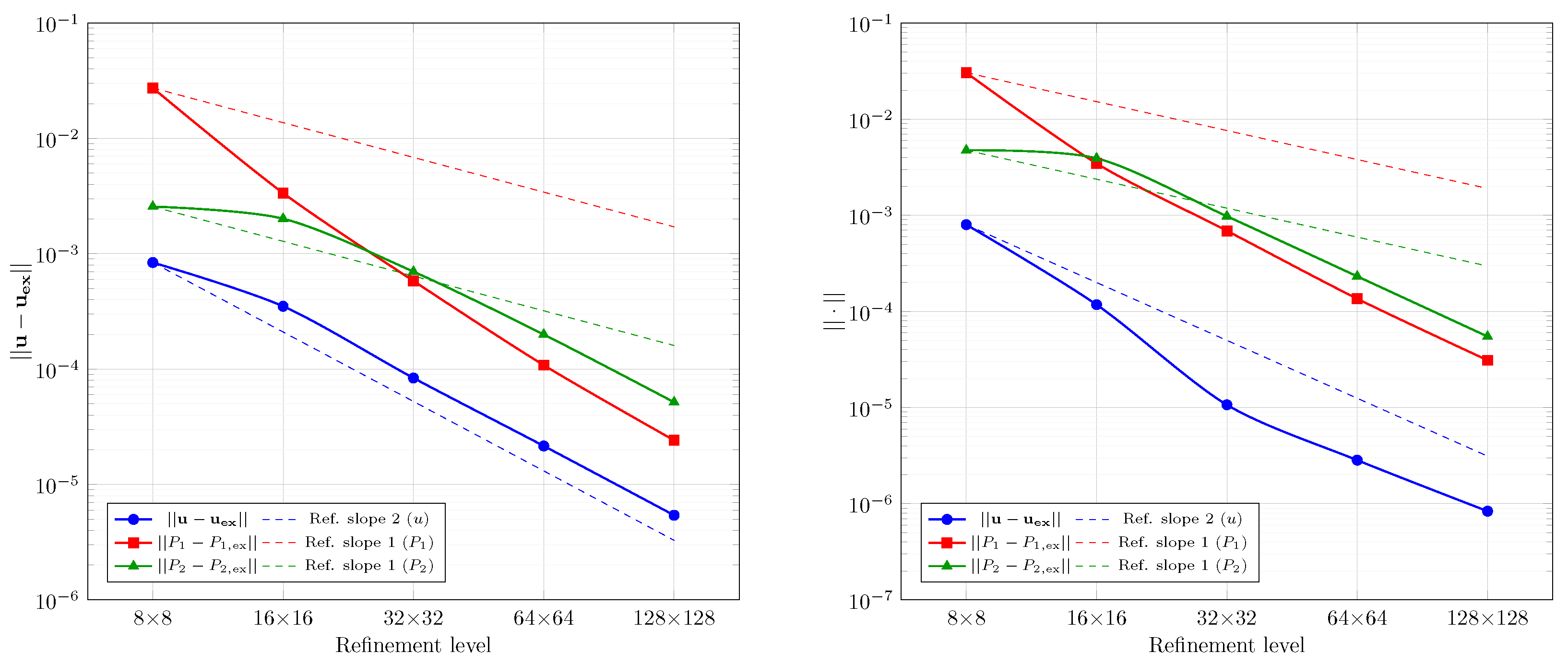
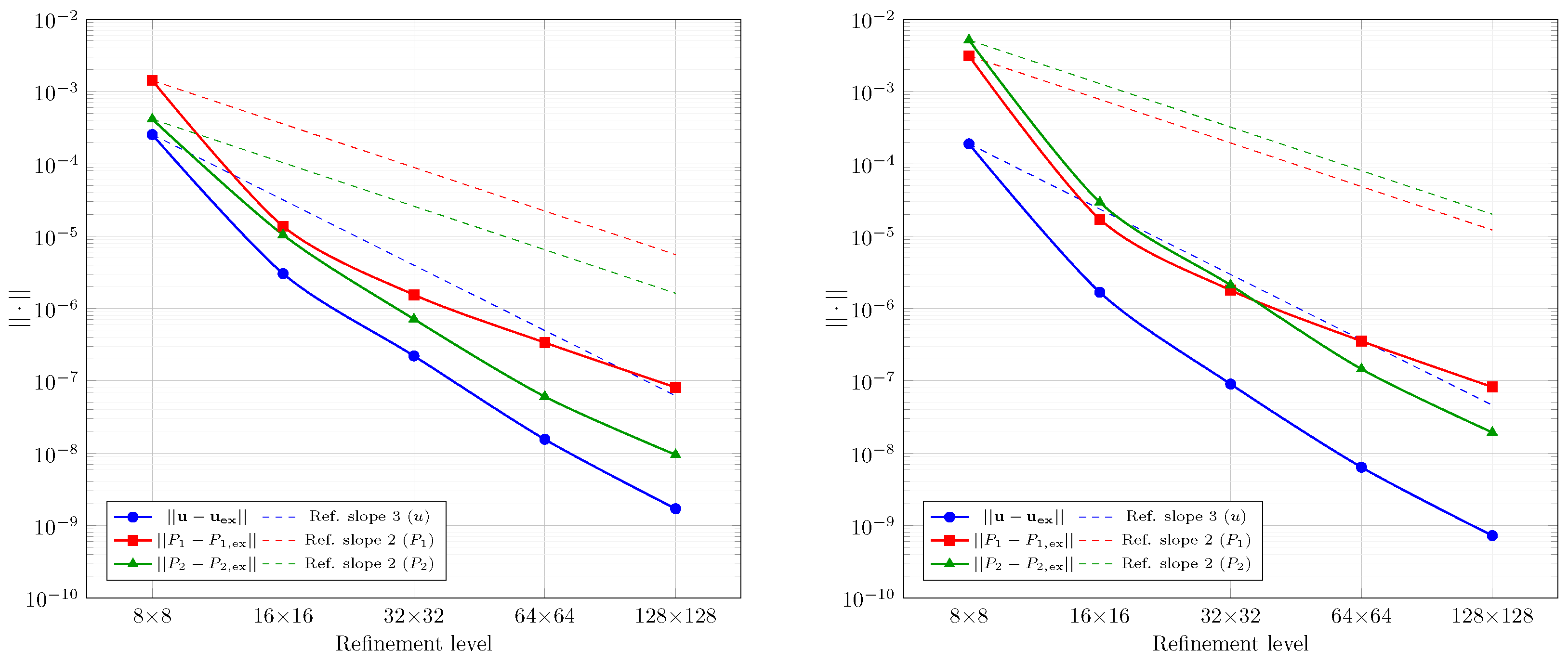
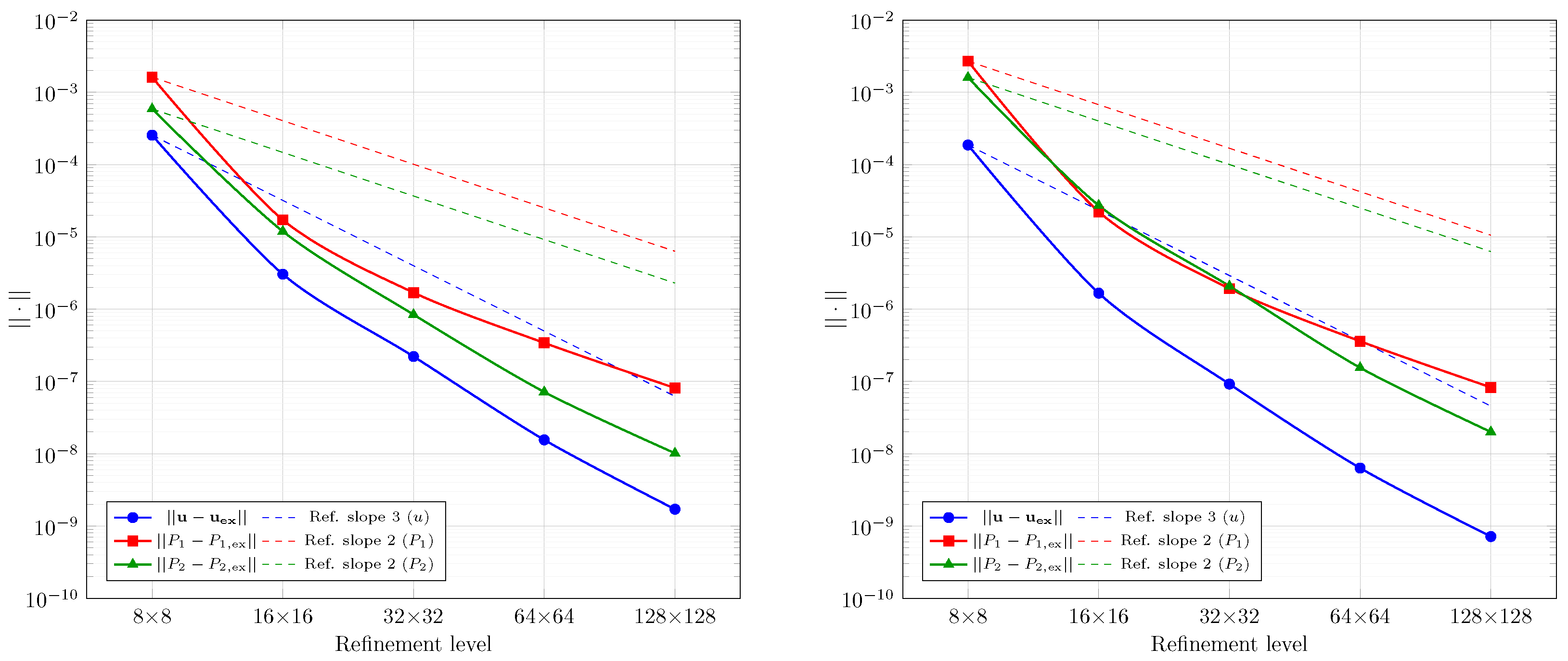
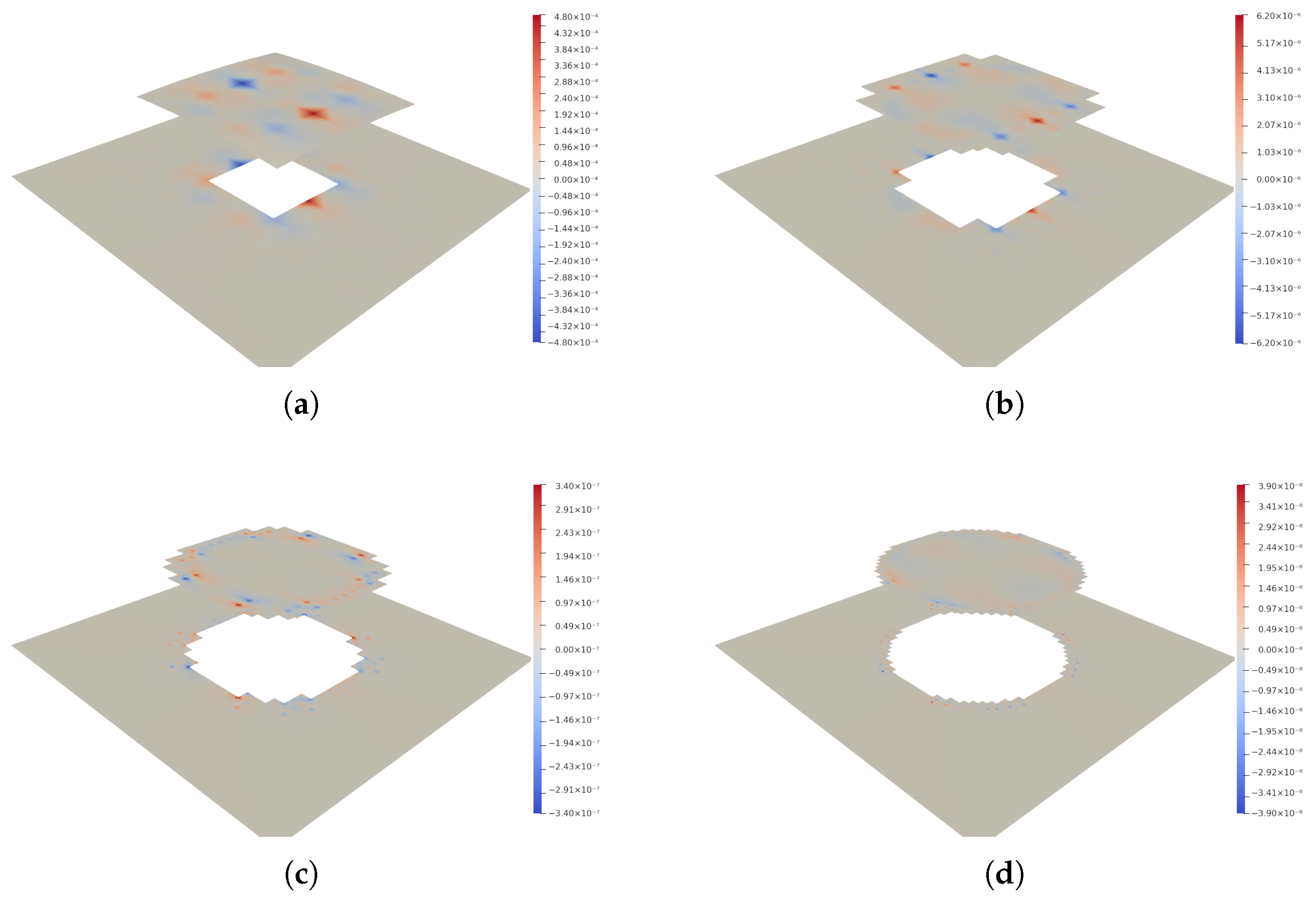
Section 6, we evaluated the proposed method for two-phase flows with complex interfaces using benchmark tests with circular and elliptical geometries. Simulations across multiple element types, mesh resolutions, and physical parameters consistently showed optimal convergence rates for velocity and pressure, matching theoretical predictions. The method effectively captured pressure jumps and suppressed spurious currents, with accuracy improving under mesh refinement. For the circular case, convergence was verified against known solutions, while for the elliptical interface, error trends were assessed through successive numerical approximations. Despite geometric complexity, the method demonstrated stable and reliable behavior, confirming its suitability for two-phase flow problems with evolving interfaces.
This work provides a useful starting point for future studies on more complex interface dynamics, varying viscosity ratios, and possible three-dimensional extensions. Such investigations will further clarify the method’s capabilities and extend its applicability to a broader class of multiphase flow problems. While the proposed method has been developed and tested in the context of two-phase flow with a single interface, extending it to general multiphase flow scenarios, particularly those involving intersecting interfaces or triple junctions, would require additional considerations. These include enhanced interface tracking methods and modified stabilization strategies near junctions. Exploring such extensions is a promising direction for future work.
Another promising direction is the extension of the method to dynamic interface benchmarks, such as capillary wave propagation and droplet coalescence, to further assess its performance in evolving interface scenarios. A meaningful next step will also be to conduct quantitative comparisons with other interface-capturing methods such as XFEM, level-set, and phase field approaches, particularly in terms of mass conservation and spurious currents.


