Article

Hierarchical Fuzzy-Adaptive Position Control of an Active Mass Damper for Enhanced Structural Vibration Suppression

by
Omer Saleem
1,
Massimo Leonardo Filograno
2,
Soltan Alharbi
2 and
Jamshed Iqbal
3,*
1
Department of Electrical Engineering, National University of Computer and Emerging Sciences, Lahore 54770, Pakistan
2
Department of Electrical and Electronic Engineering, College of Engineering, University of Jeddah, Jeddah 23890, Saudi Arabia
3
School of Digital and Physical Sciences, Faculty of Science and Engineering, University of Hull, Hull HU6 7RX, UK
*
Author to whom correspondence should be addressed.
Mathematics 2025, 13(17), 2816; https://doi.org/10.3390/math13172816
Submission received: 6 August 2025 / Revised: 21 August 2025 / Accepted: 28 August 2025 / Published: 2 September 2025

Abstract

This paper presents the formulation and simulation-based validation of a novel hierarchical fuzzy-adaptive Proportional–Integral–Derivative (PID) control framework for a rectilinear active mass damper, designed to enhance vibration suppression in structural applications. The proposed scheme utilizes a Linear–Quadratic Regulator (LQR)-optimized PID controller as the baseline regulator. To address the limitations of this baseline PID controller under varying seismic excitations, an auxiliary fuzzy adaptation layer is integrated to adjust the state-weighting matrices of the LQR performance index dynamically. The online modification of the state weightages alters the Riccati equation’s solution, thereby updating the PID gains at each sampling instant. The fuzzy adaptive mechanism modulates the said weighting parameters as nonlinear functions of the classical displacement error and normalized acceleration. Normalized acceleration provides fast, scalable, and effective feedback for vibration mitigation in structural control using AMDs. By incorporating the system’s normalized acceleration into the adaptation scheme, the controller achieves improved self-tuning, allowing it to respond efficiently and effectively to changing conditions. The hierarchical design enables robust real-time PID gain adaptation while maintaining the controller’s asymptotic stability. The effectiveness of the proposed controller is validated through customized MATLAB/SIMULINK-based simulations. Results demonstrate that the proposed adaptive PID controller significantly outperforms the baseline PID controller in mitigating structural vibrations during seismic events, confirming its suitability for intelligent structural control applications.

1. Introduction

Active Mass Damper (AMD) is a dynamic vibration control system that employs actively controlled moving masses to mitigate undesired structural vibrations caused by external excitations, such as earthquakes, strong winds, or operational loads [1]. By exerting a controlled inertial force through the motion of the mass, AMDs can effectively reduce structural displacements and accelerations, thereby enhancing the stability and safety of the system [2]. AMDs have demonstrated their effectiveness in various structural vibration suppression applications [3]. In civil structures, AMDs are used in high-rise buildings, towers, and long-span bridges to mitigate the effects of seismic and wind-induced vibrations [4,5]. In mechanical and aerospace systems, AMDs find applications in precision platforms, satellite structures, and flexible robotic arms, where vibration suppression is critical for maintaining performance and accuracy [6].
The primary advantage of AMDs over traditional passive dampers is that they provide an active real-time control, rather than relying only on the damper’s structural properties and dissipative mechanism [7]. They typically have more damping efficiency and responsiveness, which allows for more robust and practical implementation in smart structures and resilient engineering design [8]. Their adaptive response capability makes them particularly suitable for scenarios with time-varying disturbances or uncertain environmental conditions [9]. Additionally, an AMD can improve occupant comfort, operation reliability, and structural longevity by minimizing peak accelerations [10].
However, the performance of an AMD system is highly reliant on the accuracy and robustness of its position control system [11]. The mass position must be controlled accurately to provide counteracting forces that are both well-timed and in phase with the structural motion. Otherwise, the system may experience instability or a delayed control response, reducing damping performance [12]. Formulating reliable and agile control techniques for AMDs remains challenging due to model uncertainties, random external disturbances, and hardware constraints [13]. Furthermore, the dynamic coupling between the structure and the damper creates complexity that necessitates sophisticated control formulations to ensure stability, performance, and resilience in real-time operation.

1.1. Literature Review

Over the years, a wide array of control techniques has been explored in the literature to govern AMD behavior [14,15,16]. Classical control strategies like Proportional–Integral–Derivative (PID) and Fractional-Order PID (FOPID) controllers are widely used in AMD applications due to their simplicity [17,18]. Despite its reliable control yield, the PID controller lacks robustness under varying dynamics [19]. The FOPID controller extends PID control capabilities by integrating fractional calculus with the control procedure for better flexibility, but the associated parameter tuning is computationally demanding [20].
Contemporary control techniques such as Sliding Mode Control (SMC), H-infinity control, and Linear Quadratic Regulator (LQR) have been explored to enhance robustness [21,22,23]. Although the SMC methods offer robust model uncertainty handling capability and strong disturbance rejection, the inevitable chattering phenomenon can impair the actuator performance [24,25]. The H-infinity control ensures robust performance through worst-case optimization but tends to be conservative and complex [26]. The LQR offers optimal control with efficient state feedback for linear systems but lacks robustness against model variations and random external disturbances [27,28].
System variability is efficiently addressed by adaptive and optimum control techniques such as Model Predictive Control (MPC) and Model Reference Adaptive Control (MRAC) [29,30]. Although MPC improves control performance while effectively handling constraints, it is computationally demanding and model-reliant [31]. The MRAC adjusts control gains in real time to improve the controller’s adaptability to rapidly changing operating conditions. However, it is influenced by the selection of the adaptation rule [32]. Broader adaptive techniques like gain scheduling have also been investigated to provide flexibility in dynamic environments [33].
Intelligent methods, such as Fuzzy Logic and Neural Network-based controllers, can effectively handle nonlinear disturbances [34]. The fuzzy controllers are model-free intelligent controllers that rely on expert-defined rules and systematic tuning of membership functions [35]. The neural networks can learn complex behaviors and adapt online but require extensive training data and computational power [36]. Machine learning and other data-driven methods learn control policies from interaction, making them promising for uncertain environments [29]. However, their execution time, training data requirements, and computation resource requirements during learning remain significant challenges [37]. Adaptive dynamic programming has been applied for active mass damper design [38], while machine learning-based direct excitation enables rapid controller generation [39]. Similarly, magnetorheological dampers combined with adaptive neuro-fuzzy control have shown enhanced vibration reduction in marine applications [40]. A deep reinforcement learning-based framework is proposed for decoupled control of active mass drivers, effectively addressing control-structure interaction effects to enhance vibration suppression performance [41].
Although nonlinear control techniques, such as the backstepping controller, offer theoretical guarantees and structured design for stabilizing nonlinear systems, they frequently result in complex controllers that are sensitive to model errors [42]. In order to achieve robust, agile, and dependable position control of AMDs in various structural vibration suppression applications, hybrid approaches that combine optimum, adaptive, and intelligent control methodologies are becoming increasingly popular due to the aforementioned drawbacks of individual approaches.

1.2. Novel Contribution

This article contributes to developing and validating a novel hierarchical fuzzy-adaptive LQ-PID control strategy designed for robust position regulation of a rectilinear Active Mass Damper (AMD) system for structural vibration mitigation. The proposed control framework integrates classical optimal control with adaptive intelligent techniques to enhance the responsiveness and robustness of the AMD under bounded external perturbations. Methodologically, a Linear–Quadratic Regulator (LQR)-tuned Proportional–Integral–Derivative (PID) control law is formulated as the baseline regulator. This LQR optimization principle is utilized to compute optimal controller gains that balance vibration reduction and control input expenditure. A fuzzy adaptive layer is added to improve the controller’s adaptability in dynamic environments, which adaptively modulates the state-weighting matrix of the LQR performance index at every sampling instant. This adaptive modulation is governed by two feedback variables: the AMD’s displacement error and its normalized acceleration, which together ensure sensitivity to both absolute position and external excitation (disturbance) levels. The fuzzy system adaptively updates the LQR weights, leading to online adaptation of PID gains via re-solving the Riccati equation. The main contributions of this work are summarized as follows:
  • Formulation of an LQ-PID control law for precise position regulation of the AMD, combining optimal control and classical PID principles to achieve efficient damping with minimal control effort.
  • Development of a fuzzy adaptive mechanism that modulates the LQR state-weighting matrices based on the system’s displacement error and normalized acceleration to acquire self-tuning of PID gains.
  • Integration of the fuzzy and LQ-PID layers, enabling online gain adaptation while preserving asymptotic stability and robustness under vibrational disturbances.
  • Validation of the proposed controller’s effectiveness and adaptability using customized simulations in MATLAB/SIMULINK from MathWorks, Natick, Massachusetts, United States, assessing both standard step response and real-world vibrational disturbance scenarios.
The proposed control framework offers several benefits. The controller responds quickly to real-time changes in the structural dynamics by utilizing the fast-reacting and scalable feedback provided by normalized acceleration. The hierarchical adaptive design improves the controller’s vibration suppression ability while maintaining stability, making the system suitable for diverse structural applications, including buildings, towers, and flexible mechanical structures. The scheme provides a computationally efficient and practically viable solution for intelligent structural vibration control using AMDs.

1.3. Benefits of the Proposed Methodology

As outlined in Section 1.1, the conventional controllers such as the PID controller, FOPID controller, LQR, SMC and MPC have limitations. The PID controllers lack robustness under varying dynamics, the FOPID controllers demand complex tuning, the LQR struggles with fixed weightings and un-modeled exogenous disturbances, and SMC suffers from chattering. The proposed FA-PID controller introduces several innovative features that overcome these drawbacks:
Since the proposed controller is an LQR-optimized PID controller, its Lyapunov-based stability can be formally guaranteed, providing a rigorous stability proof that conventional PID-type controllers typically lack.
The hierarchical fuzzy adaptation enables real-time self-tuning of LQR weighting matrices based on displacement error and normalized acceleration. While conventional LQR controllers rely on fixed weightings and thus struggle with uncertainties, the proposed scheme continuously updates the internal weights, ensuring responsiveness to dynamic conditions.
The proposed scheme effectively suppresses seismic disturbances across diverse scenarios, where conventional controllers typically show degraded performance.
The adaptive gain tuning gently commutes between sliding modes to prevent chattering.
Unlike MPC or data-driven control methods that are computationally expensive, the proposed scheme achieves adaptability with modest computational overhead, making it practical for real-time applications.
The proposed scheme provides a balanced trade-off between fast response, low overshoot, and limited control effort compared to classical PID and LQR.
These features enhance vibration suppression performance, making the proposed method more effective and practically viable than conventional control schemes.
The idea of self-tuning the LQR-tuned PID position controller for AMDs to enhance their robustness against vibrational disturbances by using a fuzzy function of normalized acceleration and displacement error, which dynamically adjusts the LQR weighting parameters in real-time, has not been reported in the existing scientific literature. Therefore, this paper primarily focuses on realizing and validating this novel hierarchical fuzzy-adaptive control procedure.
The remaining paper is organized as follows. The derivation of the mathematical model of a rectilinear AMD system and the formulation of the baseline LQ-PID regulator are discussed in Section 2. The development and integration of the prescribed fuzzy adaptive system with the basic LQ-PID control to constitute the proposed adaptive PID controller is presented in Section 3. The parameter tuning process is discussed in Section 4. The simulation-based analysis of the proposed control scheme is presented in Section 5. The article is concluded in Section 6.

2. System Description

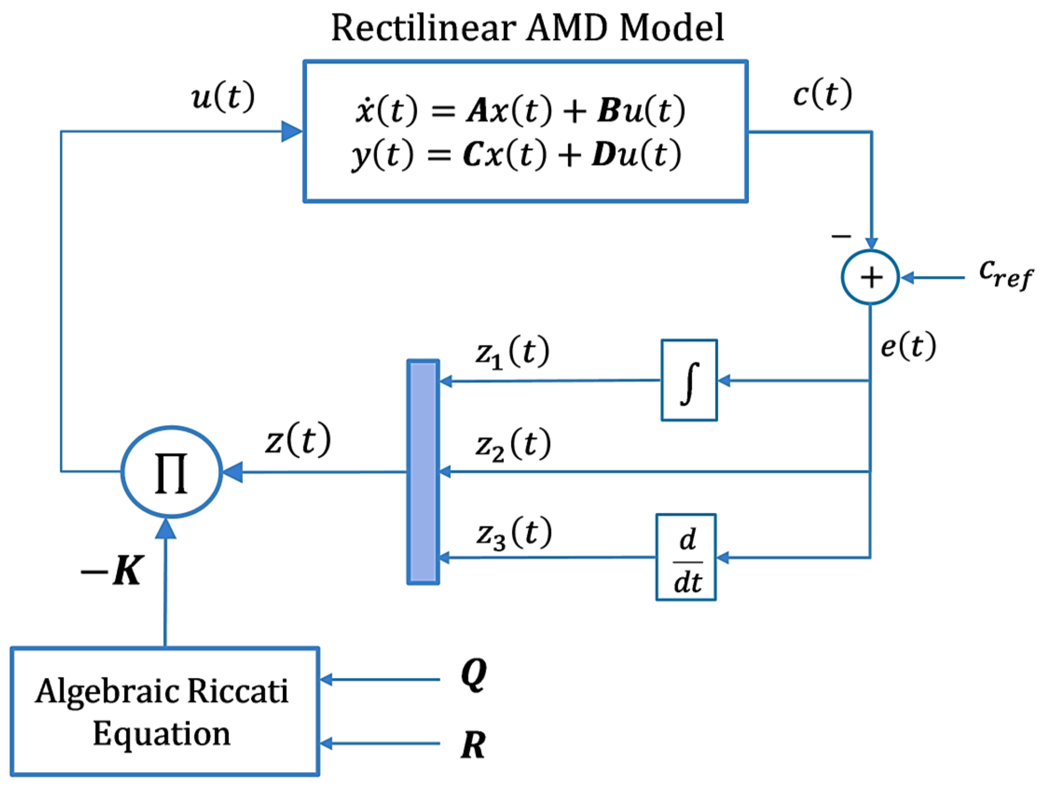
The block diagram of the rectilinear AMD system is presented in Figure 1. The modeling parameters used in this study are based on the Educational Control Product (ECP) rectilinear AMD system that was physically implemented and experimentally tested in the laboratory at Wright State University [19]. The AMD system typically consists of a single mass carriage equipped with adjustable weights and connected to a linear damper.
The lumped mass and the viscous damping coefficient are denoted by m and b , respectively. In the open-loop configuration, the control input signal is represented by u t , the output displacement by c t , and the applied input force by f t . The actual displacement of the mass m is described by x t . The linear actuation mechanism comprises a gear rack mounted on an anti-friction carriage, driven by a pinion attached to a brushless DC servo motor. The position of the mass carriage is measured via an optical encoder with a gain defined as K w . Actuation is achieved through a servo amplifier characterized by the gain K m . The hardware and software gain of the control system is denoted as K h s .

2.1. Mathematical Model

The dynamic relationship between the input force f t and the output displacement x t of the rectilinear AMD system is governed by Newton’s second law of motion as expressed in (1) [19].
M   x ¨ t + b   x ˙ t = f t
where x ¨ t and x ˙ t represent the linear acceleration and velocity of the mass M , respectively. Applying the Laplace transform to Equation (1), delivers the following expression.
M s 2 + b s   X s = F s
where s is the Laplace operator. Solving for the transfer function between the displacement X s and the input force F s , the mechanical system is described in (3).
X s F s = 1 M s s + b M
The mechanical and electrical subsystems are incorporated to derive the complete open-loop model of the prescribed AMD system. Referring to Figure 1, the actuator dynamics are expressed as shown in (4) [19].
F s = K m   U s
The displacement is related to the system output via the following expression [19].
X s = C s K w   K h s
Substituting (4) and (5) into (3) yields the overall open-loop transfer function of the system, relating the output C s to the control input U s .
C s U s = K w   K h s   K m M s s + b M = K T M s s + b M
where K T = K w   K h s   K m represents the overall steady-state gain of the system. The parameters of the ECP rectilinear AMD system were identified through second-order step response experiments presented in the dSPACE system documentation [19]. The model parameters used in this study are quantified in Table 1.
Based on the obtained parameter values, the transfer function in (6) is evaluated as shown in (7).
C s U s = 140 s s + 5.5
This transfer function accurately represents the open-loop dynamics of the practical AMD rectilinear system used in this study. The error between the reference displacement signal c r e f and the output displacement signal c t is defined in (8).
e t = c r e f c t
Here, e t is the displacement error signal and c r e f is the reference displacement. In standard regulation-based control problems, the reference signal typically does not influence the structure of the control law. Hence, the reference is treated as zero for analytical purposes, simplifying the relationship to c t = e t . Substituting this into the original transfer function yields (9).
E s U s = 140 s s + 5.5
where E s represents the displacement error signal e t in the s-domain. This transfer function can be rearranged as shown in (10).
s 2 + 5.5 s   E s = 140   U s
The corresponding second-order differential equation is obtained by applying the inverse Laplace transform and assuming zero initial conditions, as shown in (11).
e ¨ t + 5.5   e ˙ t = 140   u t
To derive the state-space model, the following state variables are defined:
z 1 t = e t   d t ,             z 2 t = e t ,             z 3 t = e ˙ t
The system’s state equations are expressed using these definitions, as shown below.
z ˙ 1 t = z 2 t z ˙ 2 t = z 3 t z ˙ 3 t = 5.5   z 3 t 140   u t
This system can be represented in the standard linear state-space form as follows.
z ˙ t = A z t + B u t ,             y t = C z t + D u t
where z t is the state vector, u t is the control input, and y t is the output. The state vector is defined as shown below.
z t = e t d t e t e ˙ t T
The matrices of the AMD system’s linear state-space model are given by (16).
A = 0 1 0 0 0 1 0 0 5.5 ,             B = 0 0 140 ,             C = 1 0 0 0 1 0 0 0 1 ,             D = 0 0 0
This state-space model of the AMD system is used to implement the PID control law.

2.2. Baseline LQ-PID Regulator Design

In this section, an LQR-based PID control strategy is developed for the rectilinear AMD system [43]. The LQR is a well-established optimal control technique widely used for regulating linear systems represented in state-space form [44]. It provides a state-feedback control law, wherein the control input is computed as a linear combination of the system’s state variables. The objective of LQR design is to minimize a predefined quadratic performance index (QPI) over an infinite time horizon, ensuring system stability and optimal trade-off between state deviations and control effort [45]. The standard QPI is given as follows.
J 1 = 1 2 0 x t T Q x t + u t T R u t d t
where Q 3 × 3 is the symmetric, positive semi-definite state penalty matrix, and R is the strictly positive control penalty scalar. The matrices Q and R define the relative importance of penalizing deviations in specific state variables and control effort, respectively. Higher values in Q or R indicate a stronger emphasis on minimizing the corresponding component in the cost function [44,46]. The penalty matrices are constructed for the AMD system considered in this work, as shown below.
Q = diag q i q p q d ,         R = α
where q i , q p , and q d are non-negative constants representing the weights for the integral, proportional, and derivative components of the displacement error, respectively, and α > 0 represents the weight of the control input. The pre-calibrated set of Q and R matrices is used to solve an Algebraic Riccati Equation (ARE), which yields a symmetric positive-definite matrix P. This solves the LQR problem. The expression for the ARE is found in (19) [44].
A T P + P A P B R 1 B T P + Q = 0
where P 3 × 3 is a symmetric positive-definite matrix. Once P is obtained, the optimal state feedback gain vector K is calculated as shown below.
K = R 1 B T P
where K = k p k i k d . The optimal state feedback control law is expressed in (21).
u t = K   z t
Expanding this equation reveals the LQR-driven PID controller in classical form.
u t = k p e t k i e t d t k d e ˙ t
A Lyapunov-based stability analysis is performed to ensure the system’s closed-loop stability under the proposed control law. Consider the following candidate Lyapunov function [44].
V t = z t T   P   z t > 0 ,           for   x t 0
The time derivative of V t is expressed as shown below.
V ˙ t = 2 z t T P z ˙ t = 2 z t T P A B K t z t = 2 z t T P A B R 1 B T P z t = z t T P A + A T P z t 2 z t T P B R 1 B T P z t
Substituting from the ARE, the expression of   V ˙ t simplifies as follows.
V ˙ t = z t T Q z t z t T P B R 1 B T P z t     < 0
Given that Q = Q T 0 and R = R T > 0 , V ˙ t is negative semi-definite, satisfying the Lyapunov stability criterion. Therefore, the LQ-PID controller guarantees asymptotic stability of the closed-loop rectilinear AMD system.
It is to be noted that the rectilinear AMD system is an underactuated system, where the number of state variables ( e t , e ˙ t , and e t d t ) describing the system dynamics exceeds the number of available independent control inputs (the voltage applied to the mass carriage, u t ). This mismatch arises because the AMD system is driven by one actuator that regulates multiple coupled states to achieve effective vibration suppression. Consequently, appropriate weighting of the states within the LQ-PID controller is essential to ensure effective regulation of all relevant dynamics despite limited control inputs. The nominal set of coefficients of matrices Q and R selected for the baseline LQ-PID controller are calibrated offline using the tuning procedure detailed in Section 4. In this study, the nominal setting of state weightages is denoted as Q = diag q i , o q p , o q d , o and R = α o . The block diagram of the LQ-PID control scheme is shown in Figure 2.

3. Proposed Fuzzy-Adaptive PID Control Law

The control and state weighting coefficients are optimized such that α > 0 and q i , q p , and q d   0 . In underactuated systems, such as the one considered here, the number of state variables exceeds the number of independent control inputs [47]. This makes using a single control input to directly regulate every state variable quite difficult. However, the LQR framework allows for targeted influence on individual state trajectories because each state variable is assigned a corresponding weight ( q i , q p , and q d ) in the state weighting matrix Q .

3.1. Adaptive Control Law Formulation

To improve control flexibility, this study presents an online fuzzy-adaptive mechanism that continuously adjusts the elements of the matrix Q t in real-time while keeping the control weighting fixed (as determined via the tuning procedure in Section 4). In contrast to the baseline LQR, which uses static and pre-calibrated weights, the suggested approach adaptively modulates each state weighting coefficient ( q i , q p , and q d ), thereby modifying the state feedback gains K t dynamically at every sampling interval [48]. In addition to improving resilience against external perturbations, this method eliminates the requirement for extensive offline adjustment of the (critical) under-specified controller parameters. The self-adjusting weights of the matrix Q t are computed online via fuzzy nonlinear scaling functions driven by the classical error and the normalized acceleration of the AMD (as shown in Section 3.3). These pre-configured scaling functions are used to generate the following time-varying weight coefficients.
Q t = diag q i t q p t q d t ,         R = α
Using the updated Q t and fixed R , the following ARE is solved at each sampling instant to yield the updated matrix P t [48].
A T P t + P t A P t B R 1 B T P t + Q t = 0
The solution of this equation delivers the time-varying gain vector.
K t = R 1 B T P t
The resulting adaptive LQ-PID control law is expressed below.
u t = K t   z t
Since, K t = k p t k i t k d t . Therefore, expanding this law reveals the adaptive LQR-driven PID controller in classical form.
u t = k p t e t k i t e t d t k d t e ˙ t
The same Lyapunov-based analysis used for the baseline LQ-PID control law, in (23), is used to guarantee the stability of the proposed fuzzy-adaptive LQ-PID controller. Consider the following candidate Lyapunov function.
V t = z t T P t z t > 0 ,           for x t 0
Its time derivative is given as follows.
V ˙ t = z t T P t A + A T P t z t 2 z t T P t B R 1 B T P t z t
Substituting from the time-varying ARE, we obtain the following expression.
V ˙ t = z t T Q t z t z t T P t B R 1 B T P t z t     < 0
If Q t = Q t T 0 and R = R T > 0 , V ˙ t is negative semi-definite. This validates the asymptotic stability of the closed-loop system under the proposed adaptive control law and satisfies the Lyapunov stability condition.

3.2. Online Weight Adaptation Rationale

The coefficients of the state-weighting matrix Q t are dynamically modified in real time by using a pre-calibrated fuzzy adaptive system. It modulates the weighting coefficients based on variations in the AMD’s state error and its normalized acceleration, ensuring smooth and bounded transitions in the said weights as operating conditions vary. The fuzzy weight-adaptation scheme is constructed using rule bases that depend on two key normalized signals: the normalized absolute displacement error e n t and the normalized relative rate of response r n t .
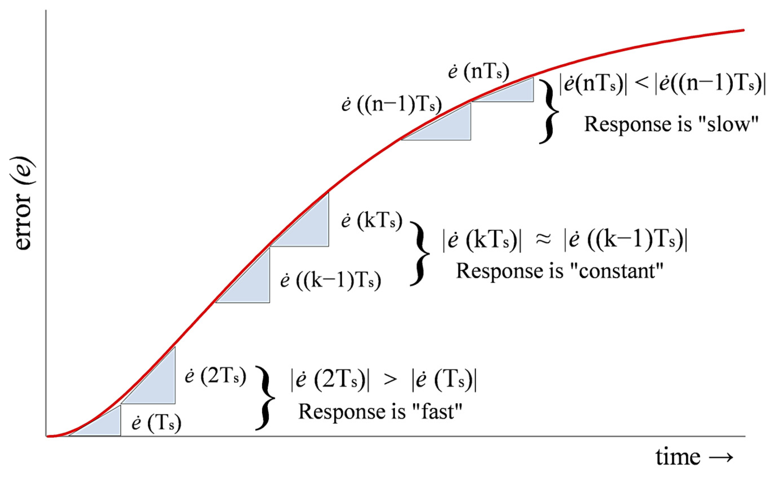
The fuzzy weight adaptation scheme is guided by the relative-rate feedback r n t , which describes the dynamic behavior of the system, that is, the speed (rapid, moderate, or slow) at which it deviates from or returns to the reference signal during startup, transient events, or external disturbances [49]. The system reaction typically transitions from rapid to moderate to slow when it goes from steady-state to transient situations, as shown in Figure 3 [44]. Adaptively self-tuning the state-weighting coefficients according to this relative rate increases the controller’s flexibility and adaptability, enabling better compensation under dynamic or uncertain conditions [50].
The qualitative relationship between the error velocity and error acceleration, as presented in Table 2, is critical in determining the system’s relative rate. Specifically, the response is characterized as:
  • Slow when the error velocity and acceleration have opposite signs.
  • Fast when the error velocity and acceleration share the same sign.
  • Moderate when the error velocity remains constant.
The aforementioned behavior is quantified by calculating the system’s relative rate as the product of the error acceleration e ¨ t and the instantaneous error velocity e ˙ t . The result is then normalized between 0 and 1 by subsequently passing this product through a bounded, odd-symmetric nonlinear function. In this study, normalization is performed by using the scaled hyperbolic tangent function. The formulation of the normalized relative rate r n t is expressed as follows [44].
r n t = 0.5 + 0.5 tanh e ˙ t × e ¨ t
The normalized relative rate generated by this formulation approaches zero for slow responses, unity for quick responses, and an intermediate value for moderate dynamics. By incorporating both the acquired relative rate signal and the classical error signal into the fuzzy inference system, the online adaptation scheme autonomously adjusts the state-weighting coefficients, enabling smooth and responsive real-time controller gain adjustment in accordance with system behavior changes.

3.3. Fuzzy Adaptive Scheme

As discussed earlier, the elements of the state-weighting matrix Q t are dynamically updated by the fuzzy inference system (FIS) in response to changes in the state error of the system [51]. To generate precise conclusions based on real-time input data, it uses a set of heuristically constructed fuzzy logic rules and pre-configured membership functions (MFs). The prescribed state weighting coefficients are modified for the rectilinear AMD system according to the following set of meta-rules:
  • Fast response with small error: Low values for q i t and high values for q p t and q d t are used. This minimizes overshoot and swiftly adjusts the control gains to dampen disturbances.
  • Fast response with large error: In order to avoid taking excessively forceful control measures that can exacerbate overshoot, moderate values of state weighting coefficients are selected.
  • Slow response (regardless of error magnitude): To apply smoother control for removing residual errors and preserving accurate tracking, q i t is increased while q p t and q d t are decreased.
A fuzzy inference system with two inputs is used to implement these rules. The inputs are the normalized relative rate r n t and the normalized absolute error e n t . The normalized error is formulated as shown below [44].
e n t = tanh e t 2
Squaring the error lessens the impact of e n t under minor state fluctuations and amplifies it under significant state fluctuations. The crisp inputs are transformed into linguistic variables using the fuzzification process. The fuzzy sets for e n t are L (Large), M (Medium), SM (Small-Medium), and S (Small). The default settings for r n t are F (fast), MF (medium-fast), M (medium), and SL (slow). The output of the fuzzy system, represented by λ e n , r n , is likewise confined between 0 and 1 and fuzzified into S, SM, M, and L. Table 3 illustrates the construction of 16 fuzzy rules [44,50]. The fuzzy implication is conducted by means of the max–min inference technique as shown in (35).
μ j = min h j e n ,   h j r n
In the fuzzy implication process, μ j denotes the degree of activation of the j t h fuzzy rule, and h j . represents the triangular MF used for the input variables. The general form of the triangular MF is given as follows.
h g = 1 + g c j b j , b j f c j 0 1 g c j b j + , 0 f c j b j + 0 , otherwise
Here, g is the generalized input variable, which can be either e n or r n . The terms b j , b j + , and c j denote the left-half width, right-half width, and centroid of the MF, respectively. This study employs symmetric triangular MFs for both input and output variables to ensure smooth and consistent fuzzy inference and aggregation. The graphical representations of these MFs are illustrated in Figure 4 and Figure 5.
The centroid defuzzification approach is used to obtain the fuzzy system’s crisp output, which is represented as follows.
λ e n , r n = j = 1 N μ j   w j j = 1 N μ j
where w j is the centroid of the output MF corresponding to the j t h rule, and N = 16 is the total number of fuzzy rules. This scalar output λ e n , r n 0 ,   1 is used to compute the time-varying coefficients of the matrix Q t in the LQ-PID control formulation as shown below.
q i t = q i , o   φ i , h φ i , h φ i , l   λ e n , r n
q p t = q p , o   φ p , l + φ p , h φ p , l   λ e n , r n
q d t = q d , o   φ d , l + φ d , h φ d , l   λ e n , r n
where q z , o (for z = p ,   i ,   o r   d ) are the base values of the state weightages as mentioned in Section 2.2. The parameters φ z , l and φ z , h are pre-calibrated scaling factors defining the lower and upper bounds of each respective state coefficient’s variation range. They are selected such that φ z , l < φ z , h . These scaling factors are chosen from the ranges φ z , l 0 ,   1 and φ z , h 0 ,   1 , and are calibrated offline using the parameter tuning methodology covered in Section 4. The resulting self-tuning state-weighting matrix Q t is defined as follows.
Q t = diag q i t q p t q d t
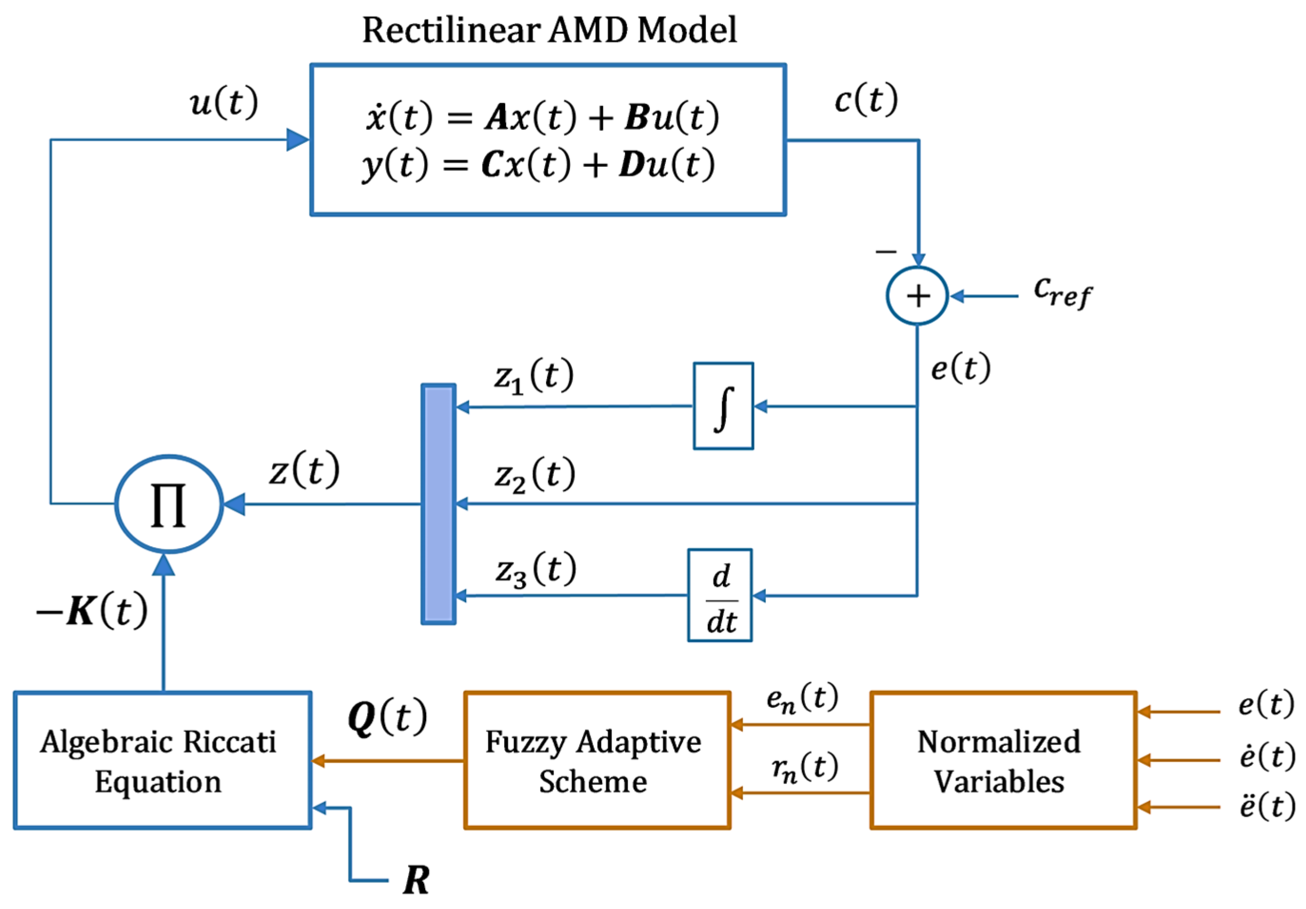
This adaptive formulation allows the controller to continuously update its gains in real-time based on the system’s error dynamics, improving responsiveness and robustness against disturbances. To summarize the control procedure: the time-varying state weighting matrix Q t is applied to the ARE to derive the solution matrix P t . This solution matrix is used to compute the self-adjusting state-feedback gain vector K t = R 1 B T P t . The resulting Fuzzy Adaptive PID (FA-PID) control law is formulated as u t = K t   z t . The block diagram of the proposed FA-PID control scheme is depicted in Figure 6.

4. Parameter Optimization Procedure

The formulation of the LQ-PID regulator, based on the QPI J 1 , inherently depends on the variations in the system’s state and control input. However, achieving optimal control performance requires appropriately assigning weights to these variables. In practice, tuning the Q and R matrices through a trial-and-error approach, often guided by limited engineering intuition or experience, may not result in precise position regulation or effective transient response [52]. To address this limitation, this study proposes the time-domain performance-based objective function J 2 , expressed as follows.
J 2 = t s 2 + O S 2 + 0 e t 2 + u t 2 d t
This function incorporates critical dynamic performance indicators, including the system’s settling time ( t s ), peak overshoot ( M p ), tracking error, and control input variations. Equal weighting is assigned to each cost function component to ensure balanced influence during the minimization process. The search space for all elements of the Q and R matrices is defined as [0, 100]. All state variables are initially assigned equal (unity) weights, such that, Q t = diag 1 1 1 and R = 1 . This forms the baseline for offline tuning. The tuning algorithm then iteratively adjusts the controller parameters by following the direction of the steepest descent of J 2 , as depicted in Figure 7 [44]. The procedure for executing these empirical tuning trials is outlined in Section 5.1. During each iteration, the LQ-PID gains are updated, and the controller is evaluated over a 5.0 s interval to regulate the AMD’s displacement at 1.0 m. The cost of the current iteration ( J 2 , n ) is compared with that of the previous iteration ( J 2 , n 1 ). If the cost decreases, the local minimum cost variable J 2 , m i n is updated, thereby ensuring the optimization proceeds in a descending direction along the cost gradient. The tuning process terminates once the maximum number of iterations ( n m a x ) is reached, or the current cost J 2 , n falls below a predefined threshold. Based on the designer’s insight, the stopping conditions were selected as J 2 , m i n < 1 × 10 3 and n m a x = 50 .
The optimized set of state and control input matrices obtained through this process are Q t = diag 25.47 18.64 3.08 and R = 1.08 . These matrices, when applied to the ARE, yield the state feedback gain vector K = 4.86 5.82 1.67 . Additionally, the scaling parameters for the fuzzy weight adaptation functions for the FA-PID controller were selected as φ i , l = 0.23 , φ i , h = 0.86 , φ p , l = 0.36 , φ p , h = 0.91 , φ d , l = 0.22 , and φ d , h = 0.68 .

5. Simulation Results and Discussions

This section outlines the methodology and results of simulations conducted to evaluate the responsiveness of the proposed FA-PID controller, benchmarked against the baseline LQ-PID controller, under real-world modeling disturbances.

5.1. Simulation Setup

The performance of the proposed FA-PID controller for active vibration suppression was evaluated through detailed time-domain simulations of the rectilinear AMD system. Simulations were carried out using MATLAB/Simulink R2020b on a 64-bit machine with a 2.4 GHz Intel Core i5 processor and 16 GB RAM, using a fixed-step solver with a 1 kHz sampling frequency to capture the system’s fast dynamics [53]. The mechanical model of the AMD system, as derived in Section 2.1, was implemented using experimentally validated parameters obtained from the ECP rectilinear setup previously tested via dSPACE at Wright State University [44]. To emulate sensor imperfections and environmental vibrations, zero-mean band-limited white noise (power = 10−4) is added to the displacement signal. This noise signal is generated in MATLAB/Simulink using the “Band-Limited White Noise” block, available in its “Sources” library. This random noise disturbance also simulates ambient vibrations in structures caused by nearby traffic, construction, or low-intensity ground motion. This noise signal is added to the displacement signal in all test cases, in addition to any other applied disturbances (where applicable).
The baseline LQ-PID and the proposed FA-PID controller were simulated under identical conditions to assess improvements in vibration suppression, transient behavior, and robustness. The fuzzy logic system dynamically tuned the LQR state-weighting matrix in real-time based on normalized error and relative rate feedback. To reflect actuator constraints, the control voltage was limited to ±20.0 V. Disturbance scenarios included step excitations, impulses, and synthetic seismic signals modeled after the earthquakes. These tests aimed to validate the controller’s effectiveness under realistic and challenging vibration profiles. Performance was evaluated in terms of peak displacement, settling time, overshoot, and control effort, providing a comprehensive assessment of the controller’s responsiveness and robustness.

5.2. Simulations and Results

The following customized simulations evaluate the performance of the LQ-PID and FA-PID control strategies.
A.
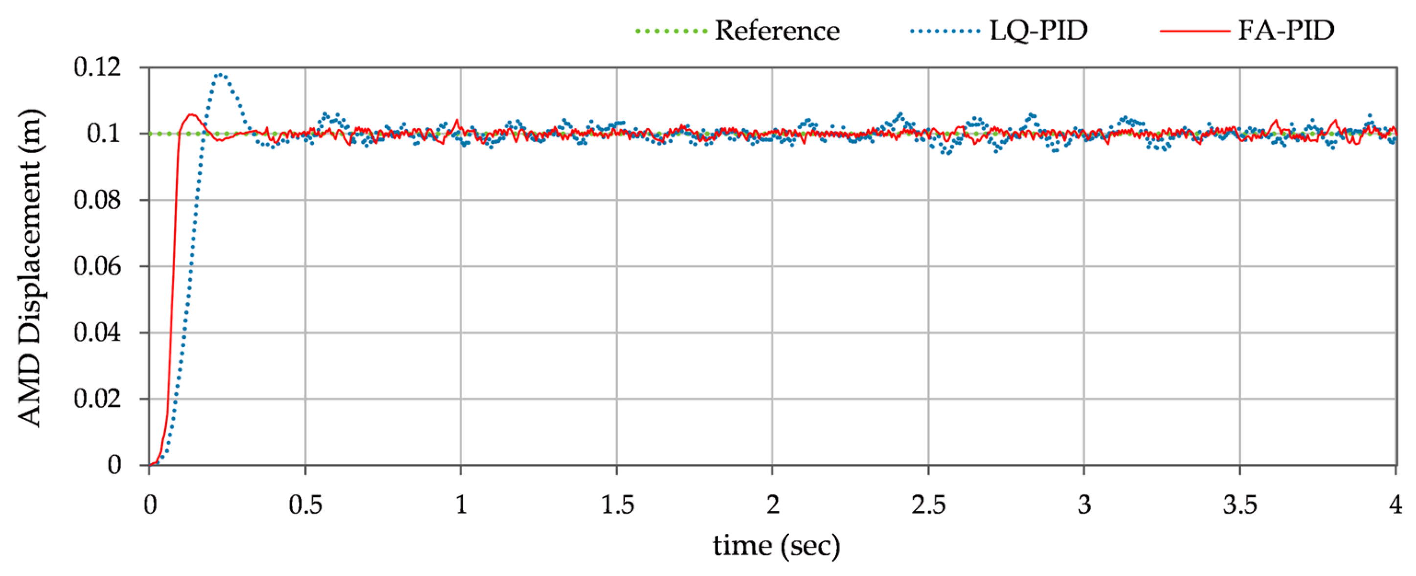
Step-reference tracking: This test case evaluates the control scheme’s step-reference tracking performance. The AMD system is subjected to an abrupt step force in order to simulate real-world situations such as machinery startup or small seismic shocks. As discussed in Section 5.1, a synthetic disturbance signal is added to the displacement signal to emulate sensor imperfections and ambient structural vibrations. This disturbance signal is configured to produce zero-mean Gaussian noise with a noise power of 10−4. The objective is to assess the system’s overshoot and response time in the event of an abrupt, prolonged displacement demand. The resulting mass displacement response x t is shown in Figure 8. The steady state response of the system is magnified and depicted in Figure 9 to assess the steady state fluctuations contributed by the additive white noise.
B.
Response under decaying sinusoidal excitation: This test evaluates the controller’s ability to suppress harmonic vibrations and maintain stability. This test case investigates the AMD system’s behavior under decaying periodic excitation, such as that brought on by HVAC systems, rotating machinery, marine wave forces, or minor seismic activities. To realistically represent the decaying sinusoidal excitation, the test introduces a synthetic decaying sinusoidal signal of 1.0 Hz frequency in the control input. The reference displacement of AMD is set to zero. The disturbance signal d 1 t used for this test case is represented in (43).
d 1 t = 4 exp 0.04 t sin 2 π t
The disturbance signal d 1 t is shown in Figure 10. The resulting vibration attenuation performance is shown in Figure 11.
C.
Response under sinusoidal and Impulsive disturbance: This test case replicates real-world events like collision shocks, explosions, or transient seismic pulses by simulating a brief, high-intensity force applied to the structure. To observe the AMD’s damping capacity and its ability to quickly restore the structure to equilibrium, synthetic pulse signals of +4.0 V magnitude and 0.5 sec duration are injected in the control input at discrete intervals. These impulsive disturbances are superimposed on the decaying sinusoidal disturbance signal d 1 t , as defined in (43). The reference displacement of AMD is set to zero. The output displacement x t under the dual excitation scenario is illustrated in Figure 12.
D.
Response under parametric variations: To assess the controller’s robustness and adaptability against parametric variations, this test simulates structural and actuator uncertainties by varying key system parameters during operation. To carry out the test, the mass of the AMD is perturbed by +20% from its nominal value to emulate the effect of payload changes at t = 10.0 s. During the test, the decaying sinusoidal disturbance d 1 t is also injected into the control input to simulate fading external excitations, while the reference displacement is kept at zero. The resulting displacement response is illustrated in Figure 13.
E.
Response under modulated Gaussian signal: This test case simulates the high-energy and transient characteristics of short-duration earthquakes. The system’s displacement response under this realistic seismic profile is analyzed to assess the AMD’s responsiveness during rapid energy buildup and decay. A sine wave modulated by a Gaussian envelope is applied to the control input to replicate a burst-like ground acceleration. The reference displacement of AMD is set to zero. The disturbance signal d 2 t used for this test is represented in (44).
d 2 t = 4 exp 0.006 t 20 sin 2 π t
The disturbance signal is shown in Figure 14. The corresponding output displacement profile is illustrated in Figure 15.

5.3. Analytical Discussion

The outcomes of the aforementioned simulations are assessed using the following key performance metrics (KPMs):
  • e r m s : Root-mean-square value of the AMD system’s position error, computed as shown in (45).
e r m s = e n 2 n
where n is the sample number.
  • t r i s e : Time taken for the system’s displacement to rise from 10% to 90% of the step amplitude.
  • t s e t : Time taken by the AMD to settle within ±0.05 m of its resting position.
  • O S : Peak overshoot due to initial displacement or excitation.
  • M p : Peak overshoot or undershoot in response to disturbances.
  • t r e c : Time required by the AMD to re-settle within ±0.05 m of its resting position, after a disturbance.
These metrics are standard for evaluating the time-domain performance of vibration suppression systems like AMDs. Table 4 summarizes the numerical analysis. The qualitative findings are discussed below. The table also presents the percentage improvement achieved by the proposed FA-PID controller for each KPM.
In Test A, the LQ-PID controller showed a sluggish response with noticeable overshoot and delayed stabilization. In comparison, the FA-PID controller reacted quickly, minimized overshoot, and achieved faster settling. Figure 8 illustrates the step-reference tracking response of the AMD system. The results of Figure 8 show that the baseline LQ-PID controller exhibits a sluggish response with noticeable overshoot and delayed stabilization. In contrast, the FA-PID controller reacts more quickly, suppresses overshoot, and achieves a shorter settling time. Moreover, as compared to the LQ-PID controller, the FA-PID controller exhibits enhanced damping against the steady-state fluctuations contributed by the additive white noise (as shown in Figure 9). These findings confirm that the fuzzy-adaptive mechanism enhances the responsiveness and robustness of the AMD system during abrupt displacement demands, such as machinery startup or seismic shocks.
In Test B, the LQ-PID controller offered limited suppression, especially near resonance. The FA-PID controller, however, adjusted the damping control effort dynamically throughout the test, significantly reducing the vibrations. In Test C, the LQ-PID controller failed to suppress the abrupt displacement promptly, leading to extended oscillations. In contrast, the FA-PID controller quickly detected the abrupt change, intensified damping, and restored equilibrium with minimal rebound, highlighting its advantage in managing short-duration disturbances. In Test D, the LQ-PID controller’s fixed gains were ineffective against the mass variation in AMD. The FA-PID controller maintained smoother tracking and suppressed state error fluctuations. Finally, in Test E, the LQ-PID controller lagged in adapting to dynamically changing operating conditions, resulting in excessive displacement. Meanwhile, the FA-PID controller quickly recognized the disturbance onset, increased damping at critical moments, and effectively mitigated peak response and post-burst oscillations.

5.4. Final Remarks

Overall, the proposed FA-PID controller consistently outperformed the conventional LQ-PID controller across all test cases. Its ability to adjust gains based on real-time system dynamics led to improved responsiveness, enhanced stability, and superior vibration attenuation, making it well-suited for real-world rectilinear AMD applications. The LQ-PID controller consistently demonstrates poor performance across all simulation cases. The FA-PID controller effectively tracks the reference displacement while efficiently damping oscillations caused by external disturbances. The enhanced robustness and faster response are attributed to the relative-rate-driven fuzzy weight-adaptation mechanism integrated into the FA-PID controller. The fuzzy weight adaptation mechanism significantly improves the system’s adaptability, enabling autonomous self-tuning of the controller gains in response to dynamic error and acceleration conditions. The controller’s heightened responsiveness is clearly reflected in the time-domain profiles observed in Figure 8, Figure 9, Figure 10, Figure 11, Figure 12, Figure 13 and Figure 14.
The simulation results consistently show that the FA-PID controller achieves lower overshoot, faster settling, and improved disturbance rejection across all test cases, including step inputs, sinusoidal excitations, impulsive shocks, parametric variations, and Gaussian-modulated seismic signals. Quantitative performance metrics summarized in Table 4 confirm significant improvements, with up to ~59% reduction in overshoot and ~27% improvement in settling time.
Compared to previous controllers reported in the literature (such as classical PID, FOPID, LQR, MPC, and SMC), the FA-PID controller provides a superior trade-off between robustness, adaptability, and computational simplicity. The hierarchical fuzzy self-tuning capability establishes the FA-PID as more effective than previously proposed approaches for active vibration suppression in AMD systems.

6. Conclusions

This article systematically develops and implements a novel FA-PID control strategy for a rectilinear AMD system to enhance structural vibration suppression under real-world disturbances and uncertainties. A two-input fuzzy weight-adaptation mechanism is integrated into the adaptive PID control law to improve responsiveness and disturbance rejection. The fuzzy unit dynamically modulates the state-weighting coefficients in real time based on a nonlinear function of the system’s normalized error magnitude and relative response rate. This allows the controller to intelligently self-tune its gains as the system transitions between transient and steady-state conditions. The relative-rate feedback enriches the system’s self-learning capability, enabling the controller to make agile gain adaptation decisions in response to rapid or sluggish deviations from equilibrium. This augmentation significantly increases the robustness of the control scheme, allowing it to adaptively balance damping intensity and response speed. The time-domain results obtained under various simulation-based test scenarios confirm the superior adaptability, faster recovery, and enhanced vibration mitigation performance of the FA-PID controller as compared to the LQ-PID controller. In conclusion, the proposed FA-PID controller demonstrates notable improvements in agility, precision, and resilience for active vibration control applications. Future work may further explore replacing the fuzzy adaptation mechanism with more advanced neuro-fuzzy, neural network-based, or data-driven adaptation schemes to improve real-time tuning flexibility under more complex operating environments. The proposed scheme can also be extended to other structural control systems and adaptive damping applications involving nonlinear or time-varying dynamics.

Author Contributions

Conceptualization, O.S.; methodology, O.S.; software, O.S. and S.A.; validation, J.I.; formal analysis, M.L.F. and S.A.; investigation, O.S. and S.A.; resources, M.L.F.; data curation, M.L.F.; writing—original draft preparation, O.S. and S.A.; writing—review and editing, J.I.; visualization, J.I.; supervision, J.I.; project administration, M.L.F. All authors have read and agreed to the published version of the manuscript.

Funding

This work was funded by the University of Jeddah, Jeddah, Saudi Arabia, under Grant No. (UJ-21-ICL-6). The authors, therefore, acknowledge with thanks the University of Jeddah technical and financial support.

Data Availability Statement

The original contributions presented in this study are included in the article. Further inquiries can be directed to the corresponding author.

Conflicts of Interest

The authors declare no conflicts of interest.

References

  1. Yang, D.H.; Shin, J.H.; Lee, H.; Kim, S.K.; Kwak, M.K. Active vibration control of structure by active mass damper and multi-modal negative acceleration feedback control algorithm. J. Sound Vib. 2017, 392, 18–30. [Google Scholar] [CrossRef]
  2. Zhang, B.L.; Liu, Y.J.; Han, Q.L.; Tang, G.Y. Optimal tracking control with feedforward compensation for offshore steel jacket platforms with active mass damper mechanisms. J. Vib. Control 2014, 22, 695–709. [Google Scholar] [CrossRef]
  3. Yang, F.; Sedaghati, R.; Esmailzadeh, E. Vibration suppression of structures using tuned mass damper technology: A state-of-the-art review. J. Vib. Control 2021, 28, 812–836. [Google Scholar] [CrossRef]
  4. Feng, J.; Liu, Z.; He, X.; Fu, Q.; Li, G. Adaptive Vibration Control for an Active Mass Damper of a High-Rise Building. IEEE Trans. Syst. Man Cybern. Syst. 2022, 52, 1970–1983. [Google Scholar] [CrossRef]
  5. Chang, S. Active Mass Damper for Reducing Wind and Earthquake Vibrations of a Long-Period Bridge. Actuators 2020, 9, 66. [Google Scholar] [CrossRef]
  6. Kraus, K.; Šika, Z.; Beneš, P.; Krivošej, J.; Vyhlídal, T. Mechatronic robot arm with active vibration absorbers. J. Vib. Control 2020, 26, 1145–1156. [Google Scholar] [CrossRef]
  7. Brodersen, M.L.; Bjørke, A.S.; Høgsberg, J. Active tuned mass damper for damping of offshore wind turbine vibrations. Wind Energy 2017, 20, 783–796. [Google Scholar] [CrossRef]
  8. Noori, M.; Narjabadifam, P. Innovative civil engineering applications of smart materials for smart sustainable urbanization. J. Civil. Eng. Urban. 2019, 9, 24–35. [Google Scholar] [CrossRef]
  9. Fei, J.; Lin, B.; Yan, S.; Ding, M.; Xiao, J.; Zhang, J.; Zhang, X.; Ji, C.; Sui, T. Chatter mitigation using moving damper. J. Sound Vib. 2017, 410, 49–63. [Google Scholar] [CrossRef]
  10. Xie, W.; Hua, Y. Structural Vibration Comfort: A Review of Recent Developments. Buildings 2024, 14, 1592. [Google Scholar] [CrossRef]
  11. Zhang, S.; Li, Q.; Zhao, X.; Liu, Z.; Li, G. Vibration Control for an Active Mass Damper of a High-Rise Building With Input and Output Constraints. IEEE/ASME Trans. Mechatron. 2023, 28, 186–196. [Google Scholar] [CrossRef]
  12. Zhang, Y.; Ma, G.; Wu, G.; Li, L. Modeling and nonlinear optimal control of active mass damper with rotating actuator for structural vibration control. Struct. Control Health Monit. 2022, 29, e2871. [Google Scholar] [CrossRef]
  13. Yang, Y.; Liu, C.; Chen, L.; Zhang, X. Phase deviation of semi-active suspension control and its compensation with inertial suspension. Acta Mech. Sin. 2024, 40, 523367. [Google Scholar] [CrossRef]
  14. Dharmajan, N.B.; AlHamaydeh, M. State-of-the-Art Review of Structural Vibration Control: Overview and Research Gaps. Appl. Sci. 2025, 15, 7966. [Google Scholar] [CrossRef]
  15. Saaed, T.E.; Nikolakopoulos, G.; Jonasson, J.E.; Hedlund, H. A state-of-the-art review of structural control systems. J. Sound Vib. 2015, 21, 919–937. [Google Scholar] [CrossRef]
  16. Rahimi, F.; Aghayari, R.; Samali, B. Application of tuned mass dampers for structural vibration control: A state-of-the-art review. Civ. Eng. J. 2020, 6, 1622–1651. [Google Scholar] [CrossRef]
  17. Ab Talib, M.H.; Mat Darus, I.Z.; Mohd Samin, P.; Mohd Yatim, H.; Ardani, M.I.; Shaharuddin, N.M.R.; Hadi, M.S. Vibration control of semi-active suspension system using PID controller with advanced firefly algorithm and particle swarm optimization. J. Ambient. Intell. Humaniz. Comput. 2021, 12, 1119–1137. [Google Scholar] [CrossRef]
  18. Jafarzadeh, O.; Sabetahd, R.; Ghasemi, S.A.M.; Zahrai, S.M. Design of a novel intelligent adaptive fractional-order proportional-integral-derivative controller for mitigation of seismic vibrations of a building equipped with an active tuned mass damper. Smart Mater. Struct. 2024, 33, 095020. [Google Scholar] [CrossRef]
  19. Al-Baidhani, H.; Kazimierczuk, M.K. Design and Implementation of Digital PID Control for Mass-Damper Rectilinear Systems. Mathematics 2024, 12, 2921. [Google Scholar] [CrossRef]
  20. Amini, M.; Waezi, Z.; Manthouri, M. Seismic control of the structures with active tuned mass damper and variable fractional order fuzzy proportional–integral–derivative controller. J. Vib. Control 2023, 29, 4302–4316. [Google Scholar] [CrossRef]
  21. Soleymani, M.; Abolmasoumi, A.H.; Bahrami, H.; Khalatbari-S, A.; Khoshbin, E.; Sayahi, S. Modified sliding mode control of a seismic active mass damper system considering model uncertainties and input time delay. J. Vib. Control 2018, 24, 1051–1064. [Google Scholar] [CrossRef]
  22. Kumar, G.; Kumar, A.; Jakka, R.S. An adaptive LQR controller based on PSO and maximum predominant frequency approach for semi-active control scheme using MR damper. Mech. Ind. 2018, 19, 109. [Google Scholar] [CrossRef]
  23. Xiang, P.; Nishitani, A. Optimum design of tuned mass damper floor system integrated into bending-shear type building based on H∞, H2, and stability maximization criteria. Struct. Control Health Monit. 2015, 22, 919–938. [Google Scholar] [CrossRef]
  24. Nguyen, S.D.; Kim, W.; Park, J.; Choi, S.B. A new fuzzy sliding mode controller for vibration control systems using integrated-structure smart dampers. Smart Mater. Struct. 2017, 26, 045038. [Google Scholar] [CrossRef]
  25. Talebitooti, R.; Darvish Gohari, H.; Zarastvand, M.; Loghmani, A. A robust optimum controller for suppressing radiated sound from an intelligent cylinder based on sliding mode method considering piezoelectric uncertainties. J. Intell. Mater. Sys. Struct. 2019, 30, 3066–3079. [Google Scholar] [CrossRef]
  26. Moutsopoulou, A.; Stavroulakis, G.E.; Petousis, M.; Pouliezos, A.; Vidakis, N. Developments in the Use of Hinfinity Control and μ-Analysis for Reducing Vibration in Intelligent Structures. Inventions 2023, 8, 119. [Google Scholar] [CrossRef]
  27. Chen, P.C.; Sugiarto, B.J.; Chien, K.Y. Performance-based optimization of LQR for active mass damper using symbiotic organisms search. Smart Struct. Syst. 2021, 27, 705–717. [Google Scholar]
  28. Khan, O.; Pervaiz, M.; Ahmad, E.; Iqbal, J. On the derivation of novel model and sophisticated control of flexible joint manipulator. Rev. Roum. Des Sci. Tech. Série Électrotechnique Et Énergétique 2017, 62, 103–108. [Google Scholar]
  29. Chen, P.C.; Chien, K.Y. Machine-learning based optimal seismic control of structure with active mass damper. Appl. Sci. 2020, 10, 5342. [Google Scholar] [CrossRef]
  30. Tianjun, Z.; Wan, H.; Wang, Z.; Wei, M.; Xu, X.; Zhiliang, Z.; Sanmiao, D. Model reference adaptive control of semi-active suspension model based on AdaBoost algorithm for rollover prediction. SAE Int. J. Veh. Dyn. Stab. NVH 2021, 6, 71–86. [Google Scholar] [CrossRef]
  31. Wang, E.; Wu, S.; Xun, G.; Liu, Y.; Wu, Z. Active vibration suppression for large space structure assembly: A distributed adaptive model predictive control approach. J. Vib. Control 2021, 27, 365–377. [Google Scholar] [CrossRef]
  32. Zeng, X.; Xiao, Y.; Zhou, M.; Zhu, Z.; Li, Y. Self-tuning vibration absorber based on model reference adaptive control. Mech. Syst. Sig. Proc. 2025, 237, 113063. [Google Scholar] [CrossRef]
  33. Ümütlü, R.C.; Ozturk, H.; Bidikli, B. A robust adaptive control design for active tuned mass damper systems of multistory buildings. J. Vib. Control 2021, 27, 2765–2777. [Google Scholar] [CrossRef]
  34. Moutsopoulou, A.; Petousis, M.; Vidakis, N.; Pouliezos, A.; Stavroulakis, G.E. Advancement in Intelligent Control for Dampening Structural Vibrations. Vibration 2024, 7, 844–862. [Google Scholar] [CrossRef]
  35. Takin, K.; Doroudi, R.; Doroudi, S. Vibration control of structure by optimising the placement of semi-active dampers and fuzzy logic controllers. Aust. J. Struct. Eng. 2021, 22, 222–235. [Google Scholar] [CrossRef]
  36. Yan, X.; Xu, Z.D.; Shi, Q.X. Fuzzy neural network control algorithm for asymmetric building structure with active tuned mass damper. J. Vib. Control 2020, 26, 2037–2049. [Google Scholar] [CrossRef]
  37. Demircioğlu, U.; Bakır, H. Artificial intelligence-based position control: Reinforcement learning approach in spring mass damper systems. Phys. Scr. 2024, 99, 046003. [Google Scholar] [CrossRef]
  38. Jia, S.; Ouyang, Y.; Wu, H.; Kou, X.; Li, Y.M. Data-driven design of vibration control with active mass damper. J. Phy. Conf. Ser. 2025, 2977, 012015. [Google Scholar] [CrossRef]
  39. Chen, P.C.; Chou, C.W.; Wang, W.J. Rapid controller generation for vibration suppression of structures using direct excitation with machine learning. J. Struct. Eng. 2024, 150, 04023237. [Google Scholar] [CrossRef]
  40. Sharma, S.K.; Sharma, R.C.; Upadhyay, R.K.; Lee, J. Enhanced ship engine vibration reduction using magnetorheological dampers and adaptive neuro-fuzzy control system. Ships Offshore Struct. 2025, 20, 143–159. [Google Scholar] [CrossRef]
  41. Yao, H.; Tan, P.; Yang, T.Y.; Zhou, F. Deep reinforcement learning-based active mass driver decoupled control framework considering control–structure interaction effects. Comput. Aided Civ. Infrastruct. Eng. 2024, 39, 1573–1596. [Google Scholar] [CrossRef]
  42. Badr, M.F.; Karam, E.H.; Mjeed, N.M. Control design of damper mass spring system based on backstepping controller scheme. Int. Rev. Appl. Sci. Eng. 2020, 11, 181–187. [Google Scholar] [CrossRef]
  43. Safakhaneh, M.M.; Farzam, M.F.; Ahmadi, H.; Farnam, A. Vibration control of structure using active tuned mass damper: A new control algorithm. J. Vib. Control 2024, 31, 2908–2919. [Google Scholar] [CrossRef]
  44. Saleem, O.; Ahmad, K.R.; Iqbal, J. Fuzzy-Augmented Model Reference Adaptive PID Control Law Design for Robust Voltage Regulation in DC–DC Buck Converters. Mathematics 2024, 12, 1893. [Google Scholar] [CrossRef]
  45. Lewis, F.L.; Vrabie, D.; Syrmos, V.L. Optimal Control; John Wiley & Sons: Hoboken, NJ, USA, 2012. [Google Scholar]
  46. Saleem, O.; Awan, F.G.; Mahmood-ul-Hasan, K.; Ahmad, M. Self-adaptive fractional-order LQ-PID voltage controller for robust disturbance compensation in DC-DC buck converters. Int. J. Numer. Model. 2020, 33, e2718. [Google Scholar] [CrossRef]
  47. Saleem, O.; Mahmood-ul-Hasan, K.; Rizwan, M. An experimental comparison of different hierarchical self-tuning regulatory control procedures for under-actuated mechatronic systems. PLoS ONE 2021, 16, e0256750. [Google Scholar] [CrossRef]
  48. Saleem, O.; Mahmood-ul-Hasan, K. Hierarchical adaptive control of self-stabilizing electromechanical systems using artificial-immune self-tuning mechanism for state weighting-factors. J. Mech. Sci. Technol. 2021, 35, 1235–1250. [Google Scholar] [CrossRef]
  49. Karasakal, O.; Guzelkaya, M.; Eksin, I.; Yesil, E.; Kumbasar, T. Online tuning of fuzzy PID controllers via rule weighing based on normalized acceleration. Eng. Appl. Artif. Intell. 2013, 26, 184–197. [Google Scholar] [CrossRef]
  50. Saleem, O. An enhanced adaptive-LQR procedure for under-actuated systems using relative-rate feedback to dynamically reconfigure the state-weighting-factors. J. Vib. Control 2023, 29, 2316–2331. [Google Scholar] [CrossRef]
  51. Zhang, H.; Wang, J.; Lu, G. Self-organizing fuzzy optimal control for under-actuated systems. J. Syst. Control Eng. 2014, 228, 578–590. [Google Scholar] [CrossRef]
  52. Das, S.; Pan, I.; Das, S.; Gupta, A. A novel fractional order fuzzy PID controller and its optimal time domain tuning based on integral performance indices. Eng. Appl. Artif. Intell. 2012, 25, 430–442. [Google Scholar] [CrossRef]
  53. Baizid, K.; Ćuković, S.; Iqbal, J.; Yousnadj, A.; Chellali, R.; Devedzic, G.; Ghionea, I. IRoSim: Industrial Robotics Simulation Design Planning and Optimization Platform Based on CAD and Knowledge ware Technologies. Robot. Comput. Integr. Manuf. 2016, 42, 121–134. [Google Scholar] [CrossRef]
Figure 1. Simplified block diagram of a closed-loop controlled rectilinear AMD system.
Mathematics 13 02816 g001
Figure 2. Block diagram of the LQ-PID control scheme.
Mathematics 13 02816 g002
Figure 3. Changes in the system’s relative rate [44].
Mathematics 13 02816 g003
Figure 4. (a) Input fuzzy MF representing e v , (b) Input fuzzy MF representing r v .
Mathematics 13 02816 g004
Figure 5. Output fuzzy MF representing λ .
Mathematics 13 02816 g005
Figure 6. Block Diagram of the proposed FA-MRA-PID Control Law.
Mathematics 13 02816 g006
Figure 7. Flow chart of the parameter tuning process.
Mathematics 13 02816 g007
Figure 8. Step-reference tracking response of the AMD system under disturbance-free conditions.
Mathematics 13 02816 g008
Figure 9. Magnified steady state response of the AMD system under disturbance-free conditions.
Mathematics 13 02816 g009
Figure 10. Waveform of the decaying sinusoidal disturbance signal, d 1 t .
Mathematics 13 02816 g010
Figure 11. Sytem’s response under decaying sinusoidal disturbance.
Mathematics 13 02816 g011
Figure 12. System’s response under decaying sinusoidal and impulsive disturbances.
Mathematics 13 02816 g012
Figure 13. System’s response under parametric variations.
Mathematics 13 02816 g013
Figure 14. Waveform of the modulated Gaussian disturbance signal, d 2 t .
Mathematics 13 02816 g014
Figure 15. Sytem’s response under modulated Gaussian disturbance.
Mathematics 13 02816 g015
Table 1. Model parameters of the ECP rectilinear AMD system [19].
ParametersDescriptionValueUnits
M Carriage and brass weight mass2.77kg
b Viscous damping coefficient15.235N/m/s
K T Overall steady-state gain140-
Table 2. Correlation between error velocity, error acceleration, and response [44].
e ˙ t e ¨ t System’s Response
PositivePositiveFast
PositiveZeroModerate
PositiveNegativeSlow
NegativePositiveSlow
NegativeZeroModerate
NegativeNegativeFast
Table 3. Fuzzy rule base for the FSR system [44].
e n           /           r n SLMMFF
SMMLL
SMSMMML
MSSMMM
LSSSMM
Table 4. Summary of simulation results.
Simulation CaseKPMControl SchemePercentage
Improvement
SymbolUnitLQ-PIDFA-PID
A e r m s m0.0130.01023.1%
t r i s e sec.0.1650.13518.2%
O S m0.0170.00758.8%
t s e t sec.0.480.3527.1%
B e r m s m0.0390.02341.0%
M p m0.1530.12717.0%
t s e t sec.32.625.521.8%
C e r m s m0.0430.02639.5%
M p m0.140.1028.6%
t r e c sec.1.421.1519.0%
D e r m s m0.0410.02734.1%
M p m−0.16−0.1131.2%
t r e c sec.18.315.216.9%
E e r m s m0.0460.02940.4%
M p m0.170.1237.0%
Disclaimer/Publisher’s Note: The statements, opinions and data contained in all publications are solely those of the individual author(s) and contributor(s) and not of MDPI and/or the editor(s). MDPI and/or the editor(s) disclaim responsibility for any injury to people or property resulting from any ideas, methods, instructions or products referred to in the content.