Article

Wave Load Reduction and Tranquility Zone Formation Using an Elastic Plate and Double Porous Structures for Seawall Protection

Center of Excellence for Ocean Engineering, National Taiwan Ocean University, Keelung 202301, Taiwan
*
Authors to whom correspondence should be addressed.
Mathematics 2025, 13(17), 2733; https://doi.org/10.3390/math13172733
Submission received: 31 July 2025 / Revised: 20 August 2025 / Accepted: 22 August 2025 / Published: 25 August 2025

Abstract

This study presents an analytical model to reduce the impact of wave-induced forces on a vertical seawall by introducing a floating elastic plate (EP) located at a specific distance from two bottom-standing porous structures (BSPs). The hydrodynamic interaction with the EP is described using thin plate theory, while the fluid flow through the porous medium is described by the model developed by Sollit and Cross. The resulting boundary value problem is addressed through linear potential theory combined with the eigenfunction expansion method (EEM), and model validation is achieved through consistency checks with recognized results from the literature. A comprehensive parametric analysis is performed to evaluate the influence of key system parameters such as the porosity and frictional coefficient of the BSPs, their height and width, the flexural rigidity of the EP, and the spacing between the EP and BSPs on vital hydrodynamic coefficients, including the wave force on the seawall, free surface elevation, wave reflection coefficient, and energy dissipation coefficient. The results indicate that higher frictional coefficients and higher BSP heights significantly enhance wave energy dissipation and reduce reflection, in accordance with the principle of energy conservation. Oscillatory trends observed with respect to wavenumbers in the reflection and dissipation coefficients highlight resonant interactions between the structures. Moreover, compared with a single BSP, the double BSP arrangement is more effective in minimizing the wave force on the seawall and free surface elevation in the region between the EP and the wall, even when the total volume of porous material remains unchanged. The inter-structural gap is found to play a crucial role in optimizing resonance conditions and supporting the formation of a tranquility zone. Overall, the proposed configuration demonstrates significant potential for coastal protection, offering a practical and effective solution for reducing wave loads on marine infrastructure.

1. Introduction

Seawalls play a crucial role in coastal defense by protecting shorelines from erosion, wave action, and extreme weather events. Serving as barriers between the sea and land, they help to prevent coastal degradation while ensuring the stability of shorelines, offshore infrastructure, and coastal communities. However, continuous exposure to powerful waves can lead to structural weakening and long-term damage. To mitigate this impact, researchers have explored various protective strategies, such as the strategic placement of breakwaters in front of seawalls. In this context, Hsu and Wu [1] employed the boundary element method to examine the heave and sway behavior of a rigid floating rectangular structure in a finite-depth water domain with a vertical seawall. Zheng et al. [2] investigated wave radiation and diffraction effects using a rigid rectangular floating structure positioned near a seawall. Furthermore, Evans and Porter [3] performed a hydrodynamic analysis of an oscillating water column system featuring a vertical surface-piercing barrier adjacent to a vertical wall. Sahoo et al. [4] investigated wave trapping by partial thin porous barriers near a vertical wall and the subsequent extension by Yip et al. [5], analyzed the trapping phenomena using flexible porous structures. In addition, Kaligatla et al. [6] examined the role of a vertical flexible submerged porous plate, emphasizing the flexibility effects of the plate and the porous characteristics on wave reflection and trapping efficiency. To analyze the influence of seabed variation on the protection of seawalls, Bhattacharjee and Soares [7] investigated oblique wave diffraction by a floating structure near a wall with stepped bottom topography. Extending this idea, Behera et al. [8] studied wave trapping by a porous barrier near a rigid wall on undulated beds, showing enhanced wave reflection and reduced wave loads compared with flat seabeds. In contrast, Kaligatla et al. [9] extended this approach by employing dual porous barriers, demonstrating that an appropriately spaced dual porous barrier system with moderate porosity can further improve wave trapping efficiency and significantly reduce wave forces on both the barriers and the seawall, offering information for effective coastal protection design. Wu et al. [10] explored wave reflection from a vertical wall by employing a horizontal submerged porous plate, utilizing the eigenfunction expansion method. Liu et al. [11] examined wave interactions with a perforated breakwater, demonstrating its effectiveness in reducing wave reflection and wave forces on seawalls. These studies contribute to a broader understanding of wave attenuation mechanisms and their role in enhancing the resilience of seawalls and coastal structures. These studies highlight ongoing efforts to improve seawall protection and mitigate wave-induced forces on coastal infrastructure.
To enhance wave height attenuation, researchers have explored the use of rectangular porous structures. Sollitt and Cross [12] pioneered the study of wave interaction with porous structure, employing EEM to analyze wave reflection and transmission. Their findings were validated against laboratory measurements, reinforcing the newly formulated dispersion relation for porous structure. Building on this, Dalrymple et al. [13] extended the analysis to include oblique wave interaction and proposed a simplified method for resolving the dispersion relation under such conditions. Later, Losada et al. [14] extended this research by investigating flow past a partially submerged porous structure using EEM, while accounting for the continuity of both velocity and pressure in vertical and horizontal directions. In a related study, Koley et al. [15] analyzed the performance of partial porous structure in mitigating wave-induced forces on a vertical seawall. Behera and Khan [16] examined wave energy attenuation using double trapezoidal porous structures with varying structural parameters. Tseng et al. [17] investigated Bragg reflections of oblique water waves by periodic surface-piercing and submerged breakwaters over periodic seabeds using the eigenfunction matching method with stepwise approximations. Their study validated Bragg resonance predictions for oblique waves, extending the understanding of wave interactions with periodic coastal structures and seabed features. Tsai et al. [18] applied the eigenfunction matching method with stepwise bottom and breakwater approximations to analyze the scattering of oblique waves and breaking by variable porous breakwaters over uneven seabeds, incorporating energy dissipation effects to improve accuracy. Ni and Teng [19] analyzed Bragg resonant reflection of water waves by rectangular porous bars on a sloping permeable seabed using a modified mild slope equation, highlighting the effects of permeability, bar number, height, and width on resonance strength. Taking the analysis further, Ni and Teng [20] examined porous trapezoidal bars, demonstrating similar parameter influences while also considering bar submergence and seabed slope, providing a comprehensive understanding of wave interactions with different porous breakwater geometries.
All the aforementioned investigations primarily concentrated on examining the scattering behavior of breakwaters, both with and without a seawall, with the aim of exploring wave interactions with an EP. Sahoo et al. [21] utilized the Fourier transform approach to investigate the scattering of water waves by a semi-infinite floating elastic plate. Chen et al. [22] examined hydroelasticity theories to analyze the response of large-scale marine structures. Kyoung et al. [23] examined a VLFS near shorelines using a finite element method, while Kaur and Martha [24] analyzed wave interaction with an EP over arbitrary seabeds using a step approximation and eigenfunction expansion method, emphasizing the influence of seabed geometry on wave transformation and structural response. In addition, Behera et al. [25] extended this line of inquiry by analyzing oblique wave scattering by a floating elastic plate over a porous bed, highlighting the role of porosity and edge conditions in wave attenuation. Furthermore, several studies have explored the interactions of wave structure in a two-layer fluid system, where Bhattacharjee and Sahoo [26], Xu and Lu [27], Lin and Lu [28] analyzed the impact of density stratification and interface position on reflection, transmission and hydroelastic response under both normal and oblique wave incidence. Since elastic plates are subjected to high wave loads that can cause structural damage, Sahoo et al. [29] examine the dissipative and reflective properties of a thick porous barrier, highlighting its potential in reducing the structural response of an EP. Based on this, Kumar et al. [30] conducted a comparative analysis of the hydroelastic response of a poroelastic plate in the presence of a thick porous structure using EEM. Recently, Sahoo et al. [31,32] examined the role of a rectangular porous structure in attenuating wave loads on a vertical seawall when an EP is present.
In view of the preceding discussions and considering the critical role of seawalls in protecting inland regions from wave-induced impacts and mitigating coastal erosion, this study aims to investigate the effectiveness of deploying a pair of BSPs in front of EP to enhance protection for the seawall by creating a tranquility zone near it. Here, the tranquility zone refers to a region where wave activity is significantly diminished due to the combined effect of wave trapping in the gap region between the structures and energy dissipation caused by the BSPs. This zone provides a calm environment with reduced wave heights and forces, thereby minimizing wave-induced stresses on the seawall. To this end, the present work analyzes the scattering of small-amplitude water waves by two BSPs in the presence of an EP placed at a finite distance from a rigid wall. A semi-analytical framework is developed based on the eigenfunction expansion method, incorporating linearized boundary conditions to describe the wave motion around the double BSP. This paper is organized as follows: Section 2 outlines the mathematical formulation that addresses the reduction in wave load on the rigid wall due to the presence of a double BSP alongside an EP. Section 3 presents the solution methodology. In Section 4, the numerical results are discussed in detail, illustrating the influence of various wave and structural parameters on the wave-induced force acting on the rigid wall, as well as on the reflection and energy dissipation characteristics. Results related to free surface elevation are also included. Lastly, Section 5 summarizes the key findings, with particular emphasis on mitigation of wave loads on the rigid wall.

2. Problem Description and Methodology

This analysis is set within a two-dimensional Cartesian coordinate system, modeling an inviscid, incompressible, and irrotational fluid that undergoes simple harmonic motion with an angular frequency of σ . As depicted in Figure 1, the entire fluid domain is partitioned into nine distinct regions. The two bottom-standing porous structures are situated in a body of water with finite depth h. Each BSP, denoted by the index i = 1 ,   2 , possesses a width b i , height a i , porosity ϵ i , inertial coefficient s i , and frictional coefficient f i . The first BSP and second BSP are separated by a horizontal distance L 1 . Furthermore, the EP of length l is introduced into the domain, positioned at a horizontal distance L 2 from the second BSP and L 3 from a rigid vertical wall. Given these fluid conditions, the velocity potential in each region j is represented as
Φ j ( x , y , t ) = Re ϕ j ( x , y ) e i σ t .
This potential satisfies the Laplace equation within each region j, as follows:
2 ϕ j x 2 + 2 ϕ j y 2 = 0 .
The boundary condition imposed on the rigid seabed is given by
ϕ j y = 0 on y = h , for j = 1 , 3 , 4 , 6 , 7 , 8 , 9 .
The linearized boundary condition applied at the free surface is expressed as
ϕ j y K ϕ j = 0 on y = 0 , for j = 1 , 2 , 4 , 5 , 7 , 9 ,
where K = σ 2 g , with g denoting the acceleration due to gravity.
The boundary conditions at the horizontal interfaces between the water and the two BSPs are expressed as
ϕ 2 = ( s 1 + i f 1 ) ϕ 3 , ϕ 2 y = ϵ 1 ϕ 3 y at y = h + a 1 , d 1 x d 2
ϕ 5 = ( s 2 + i f 2 ) ϕ 6 , ϕ 5 y = ϵ 2 ϕ 6 y at y = h + a 2 , d 3 x d 4 .
The boundary conditions at the vertical interfaces between the water and the BSPs are given by
ϕ 1 = ( s 1 + i f 1 ) ϕ 3 , ϕ 1 x = ϵ 1 ϕ 3 x at x = d 1 , h y h + a 1 ,
ϕ 4 = ( s 1 + i f 1 ) ϕ 3 , ϕ 4 x = ϵ 1 ϕ 3 x at x = d 2 , h y h + a 1 ,
ϕ 4 = ( s 2 + i f 2 ) ϕ 6 , ϕ 4 x = ϵ 2 ϕ 6 x at x = d 3 , h y h + a 2 ,
ϕ 7 = ( s 2 + i f 2 ) ϕ 6 , ϕ 7 x = ϵ 2 ϕ 6 x at x = d 4 , h y h + a 2 .
The boundary condition on EP floating at the free surface is given by
D 4 x 4 + 1 ε e K ϕ 8 y = K ϕ 8 on y = 0 ,
where D = EI ρ s g represents the flexural rigidity of the plate, with E as Young’s modulus and I = h 1 3 12 ( 1 ν 2 ) . Here, h 1 is the thickness of an EP and ν is Poisson’s ratio. Additionally, ε e = ρ e h 1 ρ s , where ρ s and ρ e are the densities of the fluid and EP, respectively.
When the EP is freely floating, the vanishing shear force and bending moment at its edges lead to the following edge conditions:
3 ϕ 8 x 2 y = 0 , 4 ϕ 8 x 3 y = 0 at ( l 1 , 0 ) and ( l 2 , 0 ) .
The continuity of both pressure and velocity across the vertical interfaces is ensured by imposing the following conditions:
ϕ 1 = ϕ 2 , ϕ 1 x = ϕ 2 x at x = d 1 , h + a 1 y 0
ϕ 2 = ϕ 4 , ϕ 2 x = ϕ 4 x at x = d 2 , h + a 1 y 0
ϕ 4 = ϕ 5 , ϕ 4 x = ϕ 5 x at x = d 3 , h + a 2 y 0
ϕ 5 = ϕ 7 , ϕ 5 x = ϕ 7 x at x = d 4 , h + a 2 y 0
ϕ 7 = ϕ 8 , ϕ 7 x = ϕ 8 x at x = l 1 , h y 0
ϕ 8 = ϕ 9 , ϕ 8 x = ϕ 9 x at x = l 2 , h y 0 .
The presence of rigid vertical seawall imposes a no-penetration condition, resulting in
ϕ 9 x = 0 at x = l 3 , h y 0 .
The far-field condition for an incident wave propagating towards the structure from the left is given by
ϕ 1 I 0 e i k 0 ( x d 1 ) + R 0 e i k 0 ( x d 1 ) cosh k 0 ( h + y ) cosh k 0 h as x ,
where k 0 is the wave number, I 0 and R 0 are the amplitude of the incident wave and the amplitude of the reflected wave, respectively. The magnitude of the reflection coefficient | R | is then given by
| R | = R 0 I 0 .
Here, the incident wave profile follows the monochromatic wave representation of linear potential theory, which assumes small-amplitude, periodic waves in intermediate water depth; alternative wave theories, such as higher order Stokes wave theory, would require a modified incident potential to account for nonlinear effects.

3. Solution Framework

To solve the boundary value problem as defined, the technique of separation of variables is utilized across every segment of the fluid domain. Consequently, the spatial parts of the velocity potential are expressed as series expansions using suitable eigenfunctions. In the open water Regions 1, 4, 7 and 9, the spatial velocity potentials that satisfy the conditions given in Equations (1)–(3), (18) and (19) are represented as follows:
ϕ 1 = I 0 e i k 0 ( x d 1 ) ψ 0 + n = 0 R n e i k n ( x d 1 ) ψ n , for Region 1 ,
ϕ 4 = n = 0 C 1 n e i k n ( x d 2 ) + D 1 n e i k n ( x d 3 ) ψ n , for Region 4 ,
ϕ 7 = n = 0 C 2 n e i k n ( x d 4 ) + D 2 n e i k n ( x l 1 ) ψ n , for Region 7 ,
ϕ 9 = n = 0 T n cos k n ( x l 3 ) ψ n , for Region 9 ,
where
ψ n = cosh k n ( h + y ) cosh k n h ,
R n , C 1 n , D 1 n , C 2 n , D 2 n , and T n are unknown complex constants, and k n is the root of the equation given by
K k n tanh ( k n h ) = 0 .
Furthermore, the velocity potentials in the porous regions, specifically Regions 2, 3, 5, and 6, are formulated to satisfy Equations (1)–(5), and are expressed as follows:
ϕ 2 = n = 0 A 1 n e i p 1 n ( x d 1 ) + B 1 n e i p 1 n ( x d 2 ) M 1 n , for Region 2 ,
ϕ 3 = n = 0 A 1 n e i p 1 n ( x d 1 ) + B 1 n e i p 1 n ( x d 2 ) Q 1 n , for Region 3 ,
ϕ 5 = n = 0 A 2 n e i p 2 n ( x d 3 ) + B 2 n e i p 2 n ( x d 4 ) M 2 n , for Region 5 ,
ϕ 6 = n = 0 A 2 n e i p 2 n ( x d 3 ) + B 2 n e i p 2 n ( x d 4 ) Q 2 n , for Region 6 .
where
M i n = cosh p i n ( h + y ) H i n sinh p i n ( h + y ) cosh p i n h H i n sinh p i n h , Q i n = ( 1 H i n tanh p i n a i ) cosh p i n ( h + y ) ( s i + i f i ) ( cosh p i n h H i n sinh p i n h ) , H i n = ( 1 G i ) tanh p i n a i 1 G i tanh 2 p i n a i , G i = ϵ i ( s i + i f i ) ,
A 1 n , B 1 n , A 2 n , and B 2 n are unknown complex constants, and p i n is the roots of the equation given by
K p i n tanh ( p i n h ) H i n ( K tanh ( p i n h ) p i n ) = 0 .
Lastly, in the EP region (Region 8), the velocity potential, which satisfies Equations (1)–(2) and (10), is expressed as
ϕ 8 = n = 2 E n e i q n ( x l 1 ) + F n e i q n ( x l 2 ) I n , for Region 8 ,
where
I n = cosh q n ( h + y ) cosh q n h .
E n and F n are unknown complex constants, and q n is the roots of the equation given by
K ( D q n 4 + 1 ε e K ) q n tanh ( q n h ) = 0 .
Utilizing the orthogonality of the eigenfunction ψ m and the matching conditions from Equations (6)–(9) and (12)–(17), we obtain the following system of equations:
I 0 U 0 m + n = 0 R n U n m n = 0 [ V n m + ( s 1 + i f 1 ) W n m ] A 1 n + B 1 n e i p 1 n ( d 1 d 2 ) = 0 ,
i k 0 I 0 U 0 m n = 0 i k n R n U n m n = 0 i p 1 n [ V n m + ϵ 1 W n m ] A 1 n B 1 n e i p 1 n ( d 1 d 2 ) = 0 ,
n = 0 ( C 1 n + D 1 n e i k n ( d 2 d 3 ) ) U n m n = 0 [ V n m + ( s 1 + i f 1 ) W n m ] A 1 n e i p 1 n ( d 2 d 1 ) + B 1 n = 0 ,
n = 0 i k n ( C 1 n D 1 n e i k n ( d 2 d 3 ) ) U n m n = 0 i p 1 n [ V n m + ϵ 1 W n m ] A 1 e i p 1 n ( d 2 d 1 ) B 1 n = 0 ,
n = 0 ( C 1 n e i k n ( d 3 d 2 ) + D 1 n ) U n m n = 0 [ X n m + ( s 2 + i f 2 ) Y n m ] A 2 n + B 2 n e i p 2 n ( d 3 d 4 ) = 0 ,
n = 0 i k n ( C 1 n e i k n ( d 3 d 2 ) + D 1 n ) U n m n = 0 i p 2 n [ X n m + ϵ 2 Y n m ] A 2 n B 2 n e i p 2 n ( d 3 d 4 ) = 0 ,
n = 0 ( C 2 n + D 2 n e i k n ( d 4 l 1 ) ) U n m n = 0 [ X n m + ( s 2 + i f 2 ) Y n m ] A 2 n e i p 2 ( d 4 d 3 ) + B 2 n = 0 ,
n = 0 i k n ( C 2 n D 2 n e i k n ( d 4 l 1 ) ) U n m n = 0 i p 2 n [ X n m + ϵ 2 Y n m ] A 2 n e i p 2 n ( d 4 d 3 ) B 2 n = 0 ,
n = 0 ( C 2 n e i k n ( l 1 d 4 ) + D 2 n ) U n m n = 2 E n + F n e i q n ( l 1 l 2 ) Z n m = 0 ,
n = 0 i k n ( C 2 e i k n ( l 1 d 4 ) D 2 ) U n m n = 2 i q n E n F n e i q n ( l 1 l 2 ) Z n m = 0 ,
n = 2 E n e i q n ( l 2 l 1 ) + F n Z n m n = 0 T n cos [ k n ( l 2 l 3 ) ] U n m = 0 ,
n = 2 i q n E n e i q n ( l 2 l 1 ) F n Z n m + n = 0 k n T n sin [ k n ( l 2 l 3 ) ] U n m = 0 , U n m = h 0 ψ n ψ m d y , V n m = h + a 1 0 M 1 n ψ m d y , W n m = h h + a 1 Q 1 n ψ m d y ,
X n m = h + a 2 0 M 2 n ψ m d y , Y n m = h h + a 2 Q 2 n ψ m d y , Z n m = h 0 I n ψ m d y .
Furthermore, applying Equation (32) in the free-edge conditions of an EP (Equation (11)), we obtain
n = 2 q n 3 E n + F n e i q n ( l 1 l 2 ) tanh ( q n h ) = 0 ,
n = 2 q n 3 E n e i q n ( l 2 l 1 ) + F n tanh ( q n h ) = 0 ,
n = 2 i q n 4 E n F n e i q n ( l 1 l 2 ) tanh ( q n h ) = 0 ,
n = 2 i q n 4 E n e i q n ( l 2 l 1 ) F n tanh ( q n h ) = 0 .
Equations (35)–(46) and Equations (48)–(51) constitute a system of equation, which are solved numerically using the Gauss elimination method in MATLAB (version R2024b). In this analysis, plane wave solutions are adopted, following the methodology outlined by Sahoo et al. [32]. The effectiveness of double BSPs in reducing wave loads on the seawall, particularly in the presence of an EP, is evaluated using several physical parameters. These include the wave force exerted on the seawall ( K w ), the free surface elevation, the reflection coefficient ( | R | ), and the dissipation coefficient defined as K D = 1 | R | 2 (see Sahoo et al. [32]).
  • Wave Force on the Seawall:
The wave force K w acting on the vertical seawall is calculated using the following expression (see Koley et al. [15]):
K w = i σ g h 2 0 h ϕ 9 ( l 3 , y ) d y .
  • Free Surface Elevation in Region 9:
The free surface elevation in Region 9 is given by (see Dean and Dalrymple [33] and Sahoo et al. [29]):
η 9 = i σ g ϕ 9 | y = 0 .

4. Results and Discussion

This section investigates the effectiveness of using a double BSP to reduce the impact of waves on the seawall in the presence of an EP. The analysis is illustrated through a series of graphs representing the wave force ( K w ) on the rigid wall, free surface elevation ( η 9 ), reflection coefficient ( | R | ), and dissipation coefficient ( K D ). In this study, the inertial coefficients s 1 and s 2 are fixed as 1, while the frictional coefficients f 1 and f 2 vary between 0 and 1, following the approach of Dalrymple et al. [13] and Sahoo et al. [34]. Unless specified otherwise, the following parameters are used throughout the analysis: I 0 = 1 , h = 5 m, b i = 0.5 , a i = 0.5 , ϵ i = 0.5 , s i = 1 , f i = 0.5 , L i / h = 3 , D / h 4 = 10 3 , l / h = 10 , L 3 / h = 5 , and k 0 h = 1 .

4.1. Validation of the Numerical Model

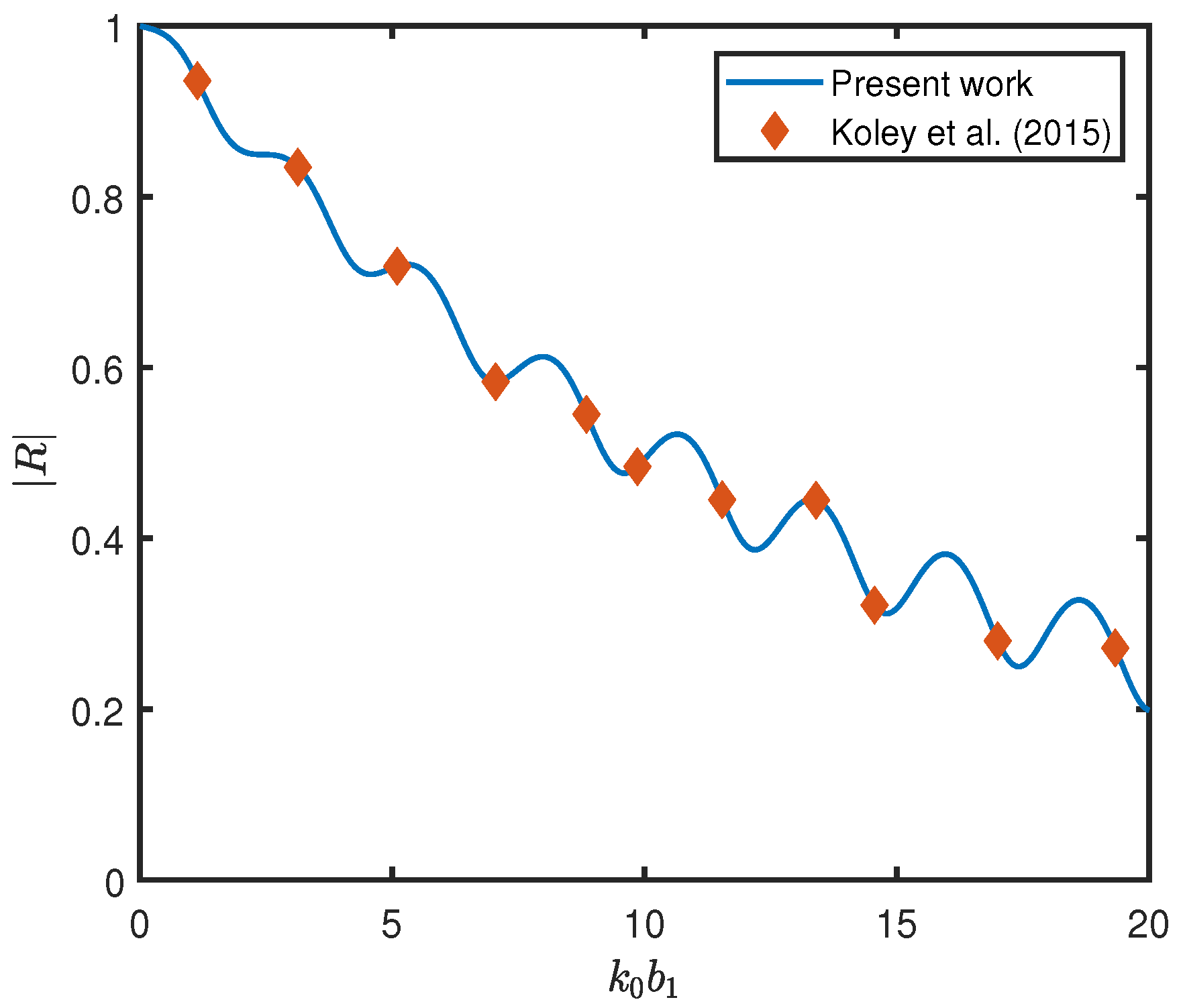
To validate the numerical results against the existing literature, it is observed that, in the absence of an EP and the second BSP (i.e., D / h 4 = 0 , ε e / h = 0 , ϵ 2 = 1 , f 2 = 0 ), the current model reduces to the configuration studied by Koley et al. [15]. Figure 2 presents the results of the present model under these conditions, with ϵ 1 = 0.437 , a 1 / h = 0.5 , f 1 = 0.25 , and L / λ = 1 ( L = L 1 + b 2 + L 2 + l + L 3 ). A close agreement is observed between the present results and those reported by Koley et al. [15], which validates the accuracy of the numerical model.

4.2. Effect of System Parameters on Hydrodynamic Coefficients

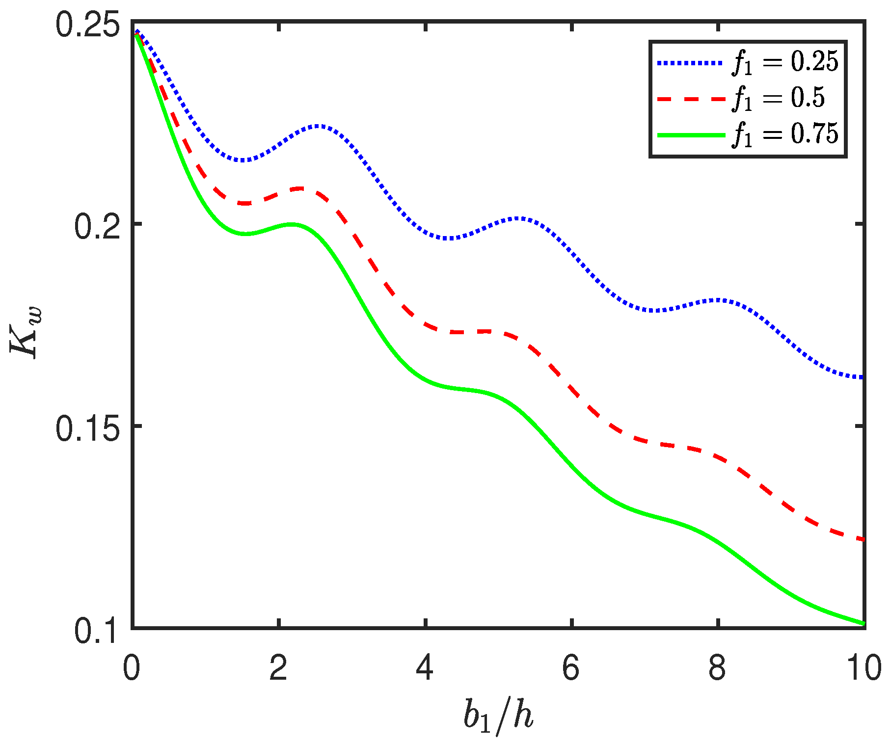
Figure 3 illustrates the variation of the wave force K w acting on the seawall as a function of the width b 1 / h of the first BSP for different values of the frictional coefficient f 1 . The results reveal that K w exhibits an oscillatory decay pattern with increasing b 1 / h . This oscillatory behavior may be attributed to the constructive and destructive interference of incident and scattered wave components, which depend on the relative positioning and width of the porous structure. As the width increases, the interaction of the waves with the BSP is altered, leading to successive regimes of enhanced and diminished reflection, thereby producing oscillations in the transmitted wave energy that reaches the seawall. Furthermore, the magnitude of K w consistently decreases with an increase in f 1 . This trend arises from the enhanced energy dissipation within the first BSP. A higher f 1 implies stronger internal resistance to flow within the pores of the BSP, resulting in greater dissipation of the wave energy. Consequently, less wave energy propagates beyond the BSP, and less wave energy is transmitted towards wall and creates a calm zone or tranquility zone near the seawall, leading to a reduced wave force on the seawall.
Figure 4 presents the variation of the wave force K w on the seawall as a function of the gap L 1 / h between the first BSP and the second BSP for different values of the height a 1 / h of the first BSP. The results reveal a periodic and oscillatory pattern in the wave force, which is primarily attributed to interference effects arising from the trapping of water waves within the gap region between the first BSP and the second BSP. As a 1 / h increases, a consistent decrease in the magnitude of K w is observed across the entire range of L 1 / h . Physically, this trend can be explained by the enhanced energy dissipation capacity of the taller first BSP. A taller BSP interacts with a larger vertical portion of the incoming wave field, increasing the volume of fluid flow through the porous medium. This increases internal friction, causing a more significant reduction in wave energy. Consequently, less wave energy propagates beyond the BSP, resulting in decreased energy transmission to the seawall and the formation of a tranquility zone near the seawall, which ultimately reduces the wave forces acting on the seawall.
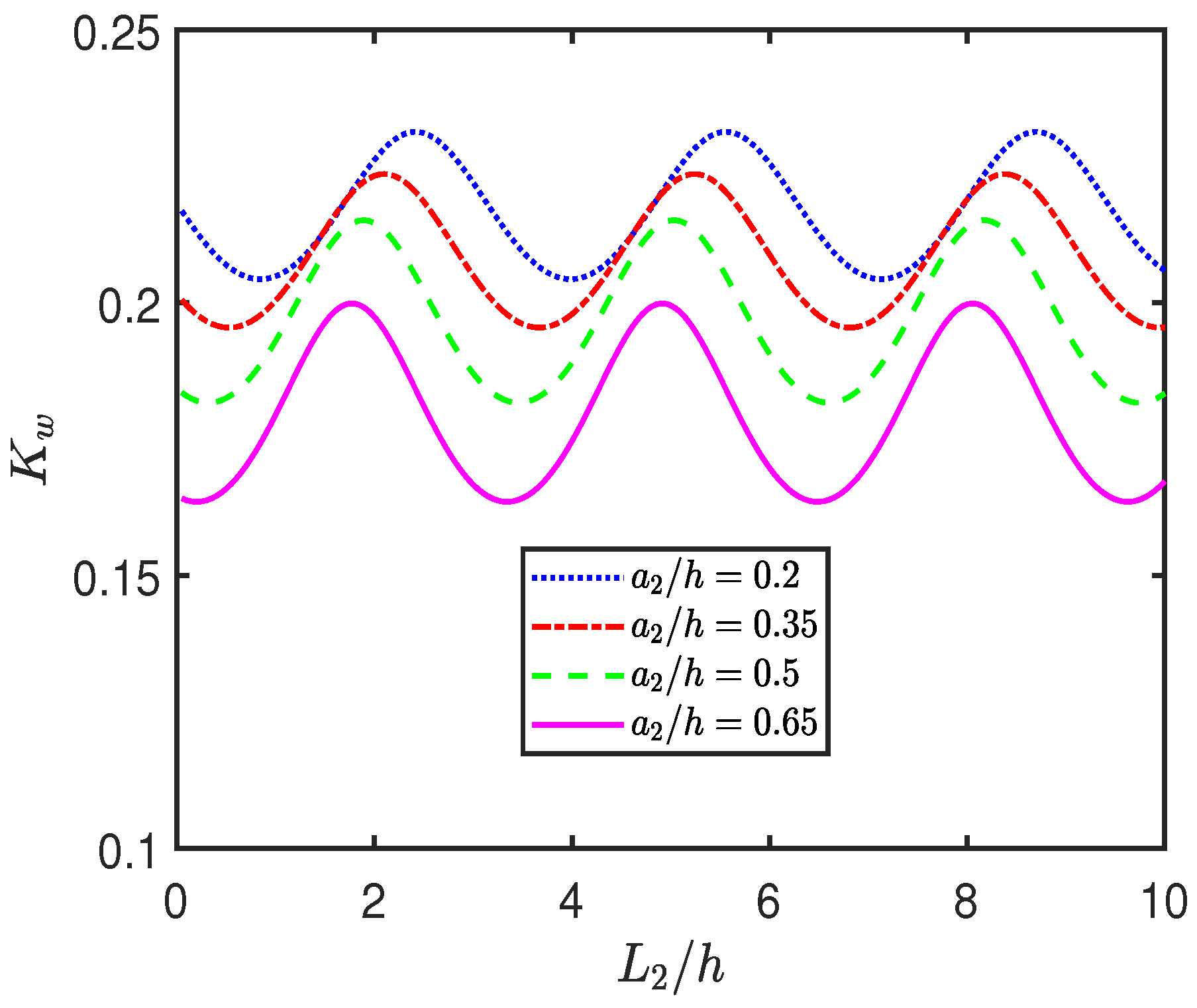
Figure 5 illustrates the variation of the wave force K w on the seawall as a function of the gap L 2 / h between the second BSP and the EP for different values of the height a 2 / h of the second BSP. The results show that K w exhibits a periodic and oscillatory pattern with respect to L 2 / h , primarily due to wave interference effects arising from multiple reflections between the second BSP and the EP. With increasing a 2 / h , two distinct trends are observed. First, the magnitude of K w consistently decreases because a taller second BSP interacts more effectively with the incoming wave field, leading to enhanced energy dissipation. This enhanced dissipation reduces the amount of wave energy propagating through the gap region and ultimately reaching the seawall, thereby decreasing the overall wave force. Second, the oscillatory pattern of K w shifts leftward toward smaller values of L 2 / h because a higher second BSP intensifies the interaction between the incident wave field and the porous surface, which changes the effective phase shift and path length of wave propagation within the confined region between the second BSP and the EP. As a result, the locations of constructive and destructive interference shift, causing the oscillatory pattern of K w to appear at lower values of L 2 / h .
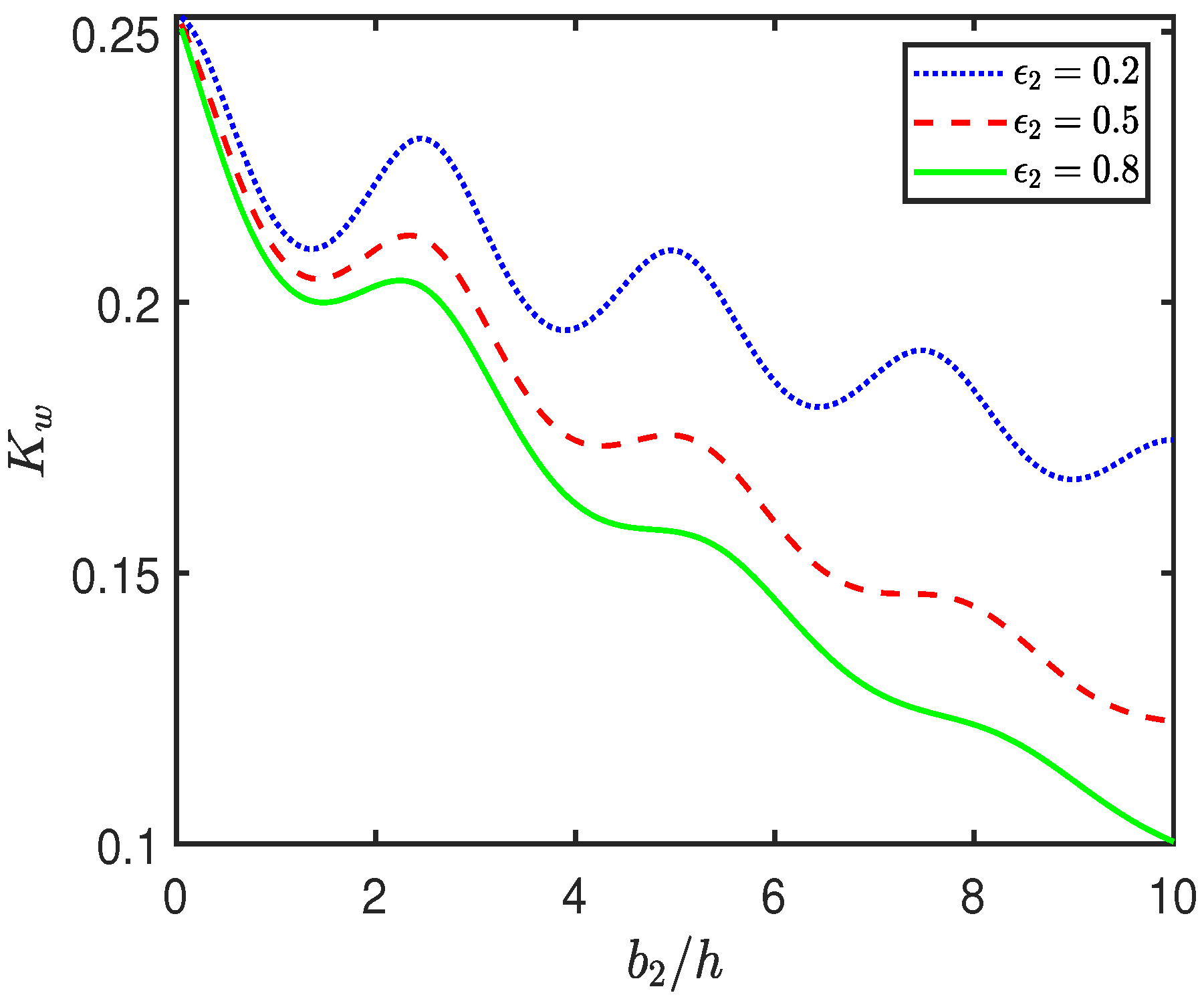
Figure 6 presents the variation of the wave force K w on the seawall as a function of the width b 2 / h of the second BSP for different values of its porosity ϵ 2 . The results show that K w decreases in an oscillatory manner with increasing b 2 / h , consistent with the pattern observed in Figure 3 for the first BSP. This oscillatory trend is primarily due to interference effects between the incident, reflected, and transmitted wave components. As the width of the second BSP varies, the phase relationship between the multiple wave modes changes, leading to alternating constructive and destructive interference. This results in fluctuating wave amplitudes in the region near the seawall, thus producing an oscillatory decay in the wave force. Moreover, a clear reduction in K w is observed with increasing ϵ 2 . This behavior can be physically explained by the enhanced wave energy dissipation capacity of the porous medium. A higher porosity allows for greater dissipation by the BSP, thus reducing the energy transmitted downstream to the seawall. This trend parallels the influence of the frictional coefficient f 1 in Figure 3, where an increase in f 1 also results in enhanced energy dissipation.
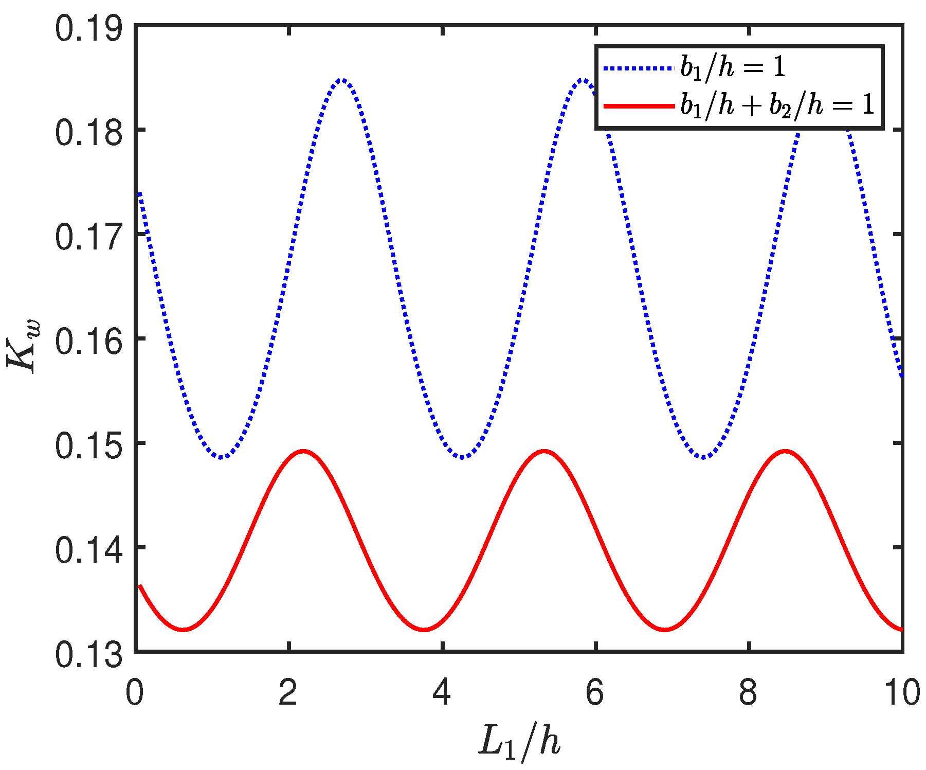
Figure 7 illustrates the variation of the wave force K w acting on the seawall as a function of the gap L 1 / h between two BSPs, considering two different configurations: (a) a single BSP with b 1 / h = 1 and (b) two BSPs with a combined width b 1 / h + b 2 / h = 1 . The results indicate that K w exhibits a periodic and oscillatory pattern as L 1 / h varies. This oscillatory behavior arises primarily from wave interference phenomena caused by multiple interactions among incident and reflected wave components. The gap region L 1 / h acts as a resonant cavity, where standing wave patterns form due to the confinement of wave motion. These standing waves alternate between constructive and destructive interference as the gap distance changes, leading to periodic fluctuations in the wave force experienced by the seawall. Furthermore, the results demonstrate that the wave force on the seawall is consistently lower in the case of two BSPs compared with a single BSP, although the total porous width remains the same. This reduction in the wave force on the wall can be physically explained by the phenomenon of wave energy trapping. When two BSPs are present, the region between them acts as a secondary chamber that facilitates wave trapping and promotes repeated scattering and internal reflections. This localized trapping increases the number of interactions of the waves with the porous media, leading to enhanced energy dissipation within the structures. Consequently, a lower proportion of wave energy reaches the seawall, resulting in a significant reduction in wave-induced force. This behavior underscores the importance of spatial configuration in porous breakwater design; not just the total porous width but also the distribution and relative positioning of porous elements can significantly affect wave transformation and load mitigation performance.
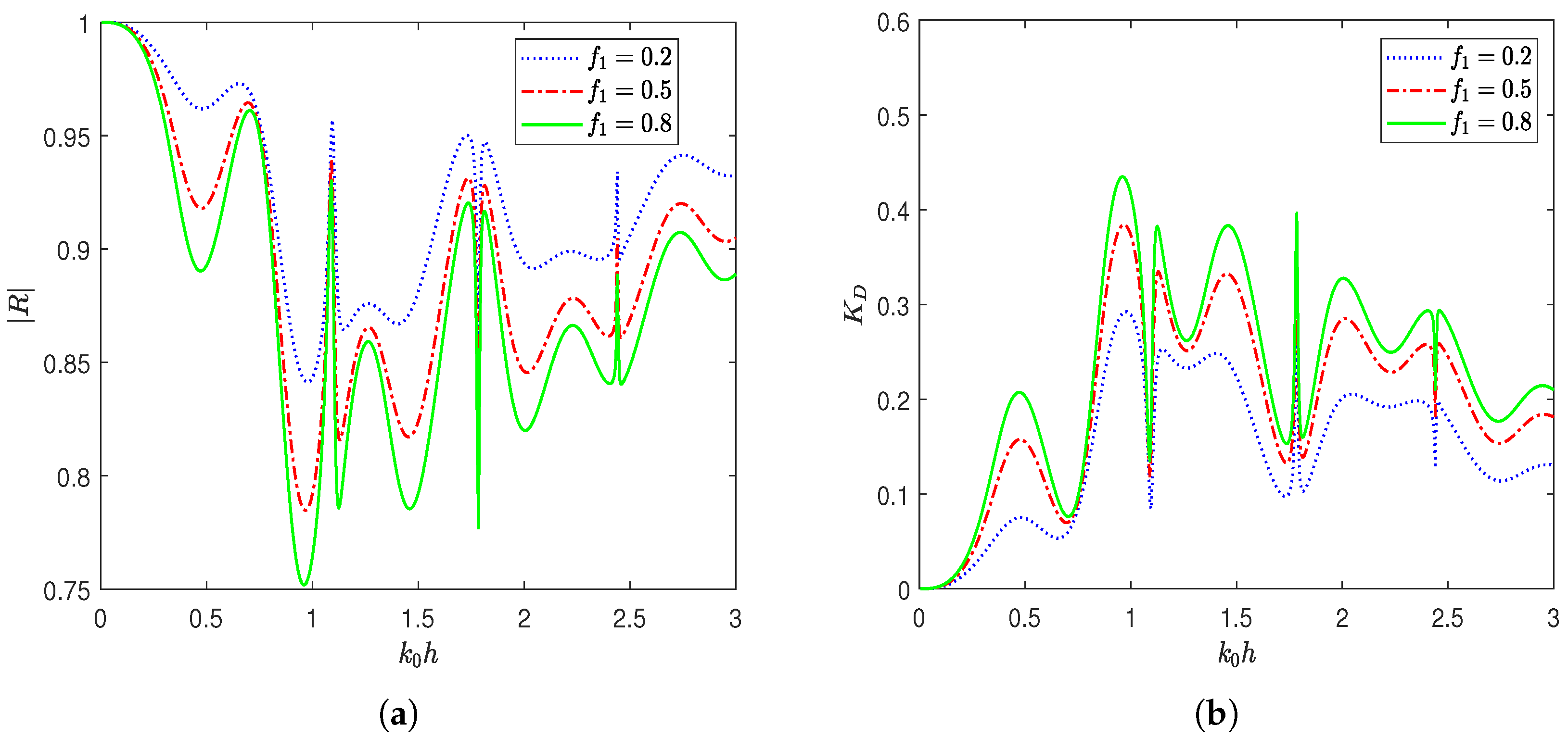
Figure 8 presents the variation of the reflection coefficient ( | R | ) and the dissipation coefficient ( K D ) as functions of the wavenumbers k 0 h for various values of the frictional coefficient f 1 of the first BSP. As shown in Figure 8a, | R | exhibits a periodic and oscillatory pattern with respect to k 0 h . At lower values of k 0 h , corresponding to longer waves, | R | approaches unity, indicating nearly complete wave reflection. However, with increasing k 0 h , distinct dips in | R | are observed, signifying reduced reflected wave energy. Notably, | R | decreases with an increase in f 1 , where the curve for f 1 = 0.8 consistently lies below those for f 1 = 0.5 and f 1 = 0.2 . This behavior highlights the role of internal resistance within the first BSP, as a higher f 1 implies enhanced damping and greater energy loss due to internal fluid motion resistance, thereby reducing the wave reflection. Conversely, Figure 8b presents the variation of K D , which generally increases with k 0 h and exhibits pronounced peaks that correspond inversely to the dips in | R | . This inverse relationship reflects the principle of energy conservation: a decrease in reflected energy is compensated by an increase in energy dissipation. K D is found to be highest for f 1 = 0.8 , followed by f 1 = 0.5 and f 1 = 0.2 , thereby confirming that a higher frictional coefficient enhances wave energy dissipation. Moreover, the oscillatory behavior in both | R | and K D with respect to k 0 h is indicative of wave interference and resonance effects occurring within the gap region. These patterns arise due to multiple internal reflections and interactions between the incident, reflected, and transmitted waves. As such, specific wavenumbers correspond to conditions of constructive or destructive interference, leading to enhanced or suppressed reflection and dissipation, respectively. Notably, the curves for both | R | and K D exhibit non-smooth behavior, particularly in the intermediate to high wavenumber regime. This lack of smoothness is due to the underlying physical processes that govern the wave structure interaction. Specifically, the presence of multiple interfaces gives rise to multiple internal reflections and resonant interactions within the system. These interactions cause sharp transitions and interference patterns in the reflected and dissipated wave energy, especially when the incident wavelength becomes comparable to the geometric features of the system. Furthermore, the inclusion of porous structures introduces complex-valued wavenumbers, which modify the phase and amplitude of the transmitted and reflected waves in a frequency-dependent manner, further amplifying the sensitivity of the solution.
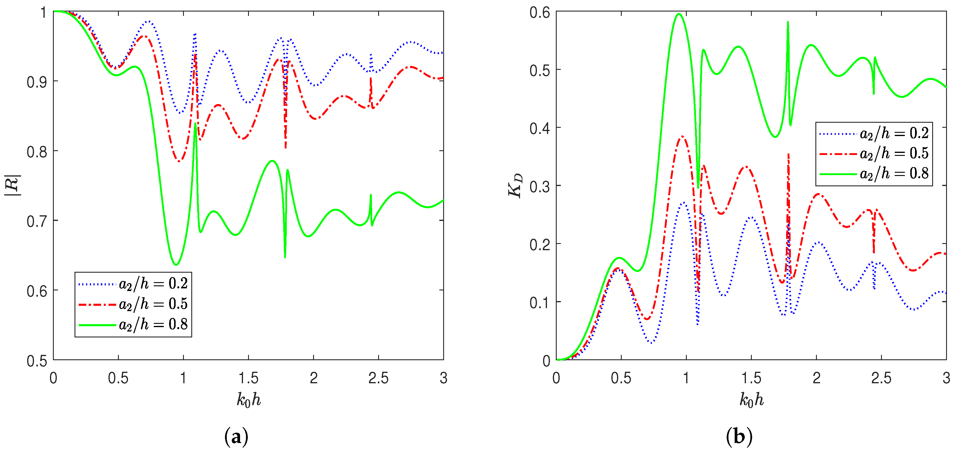
Figure 9 presents the variation of the reflection coefficient ( | R | ) and the dissipation coefficient ( K D ) as functions of the wavenumbers k 0 h for various values of the height a 2 / h of the second BSP. As depicted in the figure, | R | and K D show an oscillatory trend similar to that observed in Figure 8. A key observation is the systematic decrease in | R | with an increase in height a 2 / h . The curve corresponding to a 2 / h = 0.8 consistently exhibits the lowest values of | R | , compared with the cases of a 2 / h = 0.5 and a 2 / h = 0.2 . Physically, this behavior can be attributed to the fact that a higher second BSP introduces a larger interaction zone for wave–structure coupling, increasing the opportunity for wave energy to dissipate, leading to a reduction in reflected energy. This trend is further corroborated by the behavior of K D , illustrated in Figure 9b, which increases with k 0 h and exhibits peaks that align with the dips in | R | , consistent with the energy conservation framework previously discussed in Figure 8. K D increases substantially with increasing a 2 / h , with the maximum dissipation observed for a 2 / h = 0.8 . This indicates that a taller BSP facilitates a more effective dissipation of wave energy due to enhanced fluid structure interaction within the BSP.
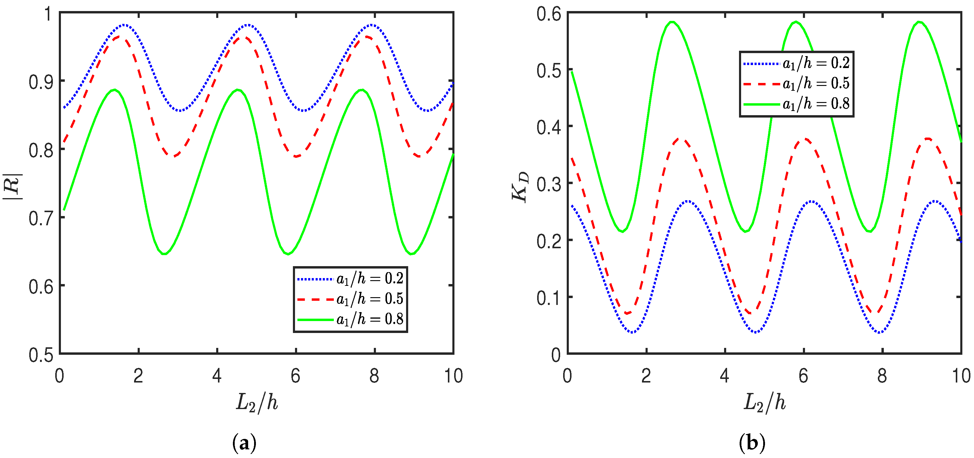
Figure 10 presents the variation of the reflection coefficient ( | R | ) and the dissipation coefficient ( K D ) as functions of the gap L 2 / h between the second BSP and the EP for various values of the height a 1 / h of the first BSP. The results reveal that both | R | and K D exhibit oscillatory and periodic behavior with respect to L 2 / h . This oscillation arises from the interference of multiple wave components incident, reflected, and transmitted within the confined gap region. The interaction among these waves produces standing wave patterns, resulting in constructive and destructive interference, which manifests itself as periodic variations in the reflection and dissipation characteristics. Furthermore, as a 1 / h increases, | R | decreases, while K D increases correspondingly. Physically, this behavior can be attributed to the increase in the interaction length of the BSP. A taller BSP offers a larger surface area and is greater for wave damping. As a result, more wave energy is dissipated within the structure, reducing the energy available for reflection and thereby lowering | R | . In addition, it is observed that the positions of the extrema (peaks and troughs) in both | R | and K D shift with increasing a 1 / h . Specifically, the peaks of | R | shift toward smaller values of L 2 / h , while the peaks of K D shift toward larger values of L 2 / h . This phase shift can be explained by the change in effective wave propagation characteristics caused by the increased structure height. A taller porous structure alters the local hydrodynamic environment, effectively modifying the phase shift within the gap region. This leads to a change in the resonance condition, thus shifting the interference pattern and the corresponding extrema of | R | and K D with respect to L 2 / h .
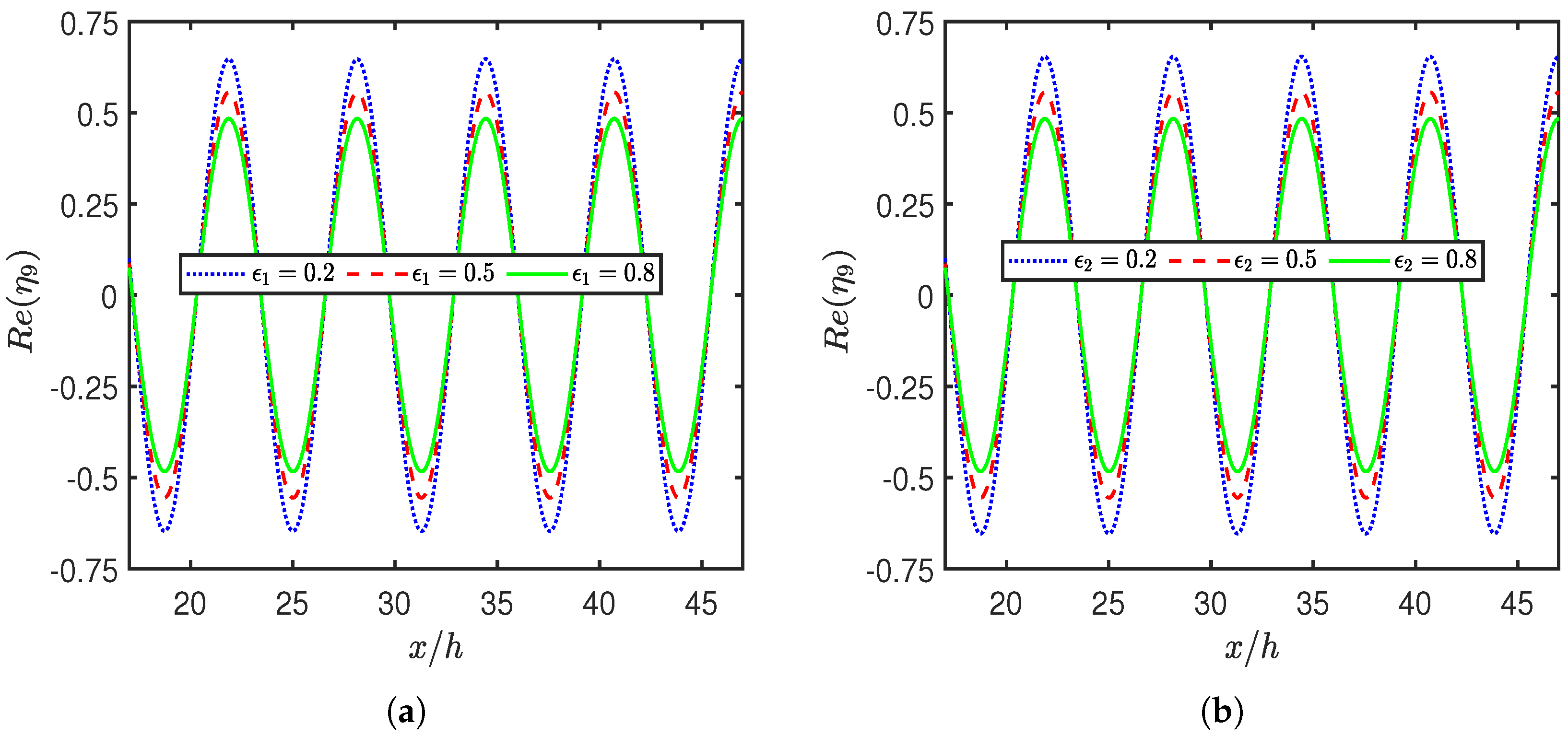
Figure 11 and Figure 12 illustrate the variation in free surface elevation R e ( η 9 ) in the confined region between the EP and the seawall for different values of the porosity parameters ( ϵ 1 and ϵ 2 ) and the heights ( a 1 / h and a 2 / h ) of the first BSP and the second BSP, respectively. In Figure 11, it is observed that an increase in porosity leads to a significant reduction in surface elevation, attributed to increased wave energy dissipation, since higher porosity facilitates greater fluid flow through the porous structures, thereby diminishing the transmission of wave energy toward the seawall and promoting the development of a tranquility zone adjacent to it. Similarly, Figure 12 shows that increasing heights a 1 / h and a 2 / h further reduces the free surface elevation, as taller structures offer an increased obstruction to wave propagation, enhancing energy absorption within the porous structures, thereby effectively limiting the wave energy reaching the seawall and fostering the establishment of a tranquility zone in its vicinity.
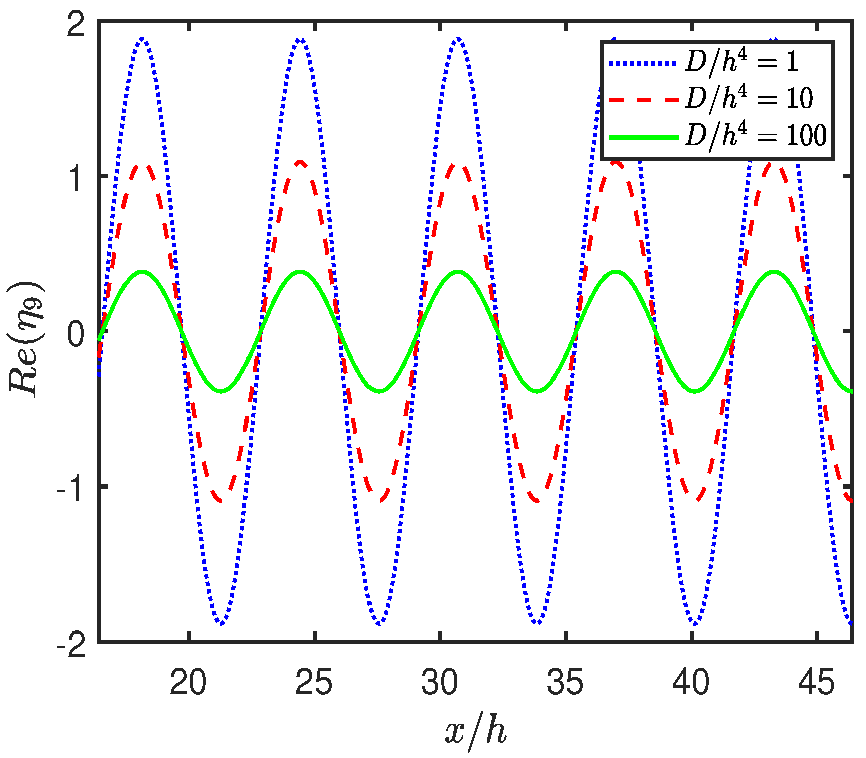
Figure 13 presents the variation in the free surface elevation R e ( η 9 ) for different values of the flexural rigidity D / h 4 of the elastic plate (EP). The results clearly indicate that as the flexural rigidity increases, the free surface elevation in Region 9 decreases. This trend arises because a higher flexural rigidity enhances the structural stiffness of the EP; thus, the EP behaves more like a rigid barrier, which acts as an effective wave reflector. This limits the vertical displacement of the water surface and decreases the amplitude of surface oscillations, thus lowering the free surface elevation in the vicinity of the seawall.
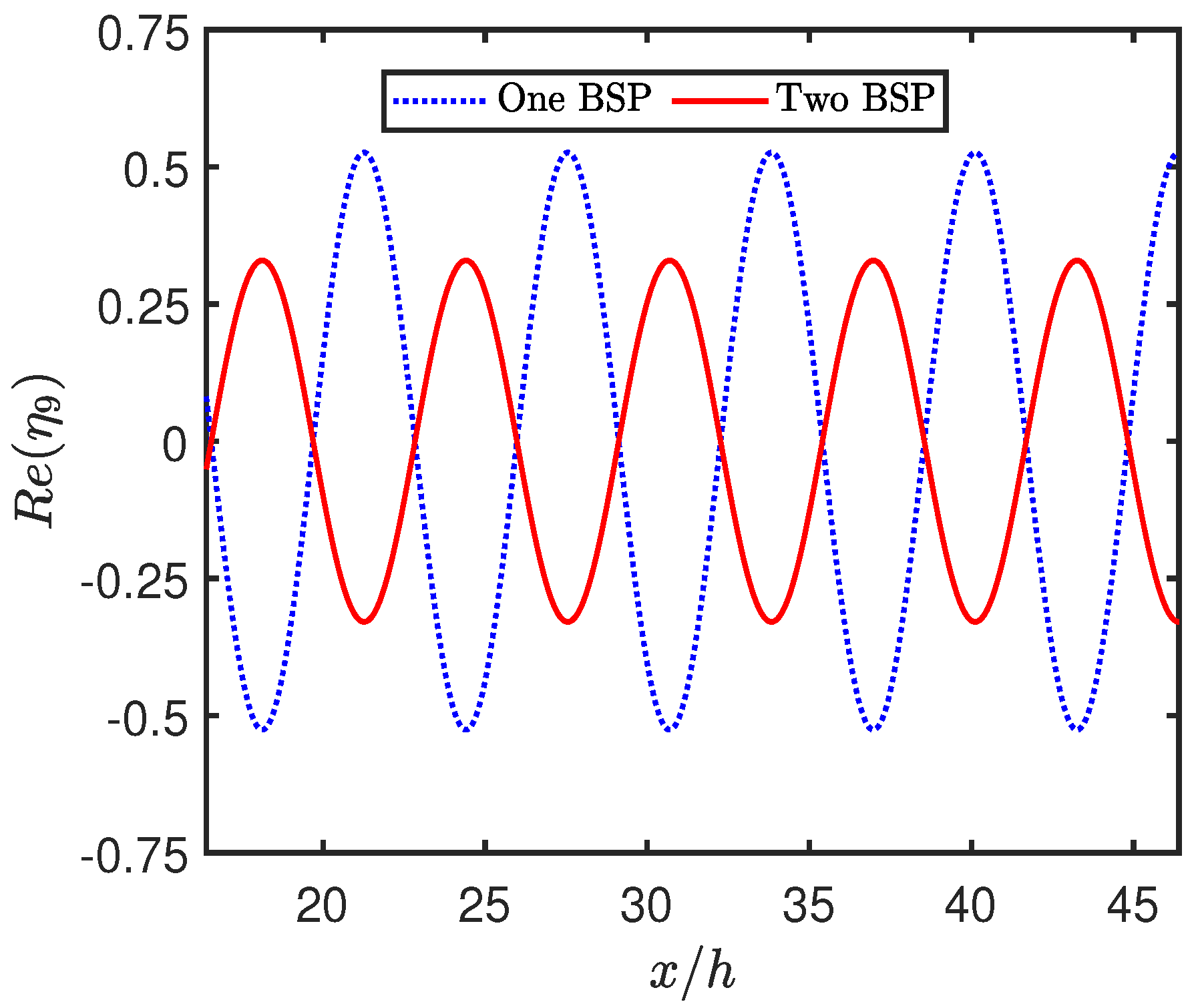
Figure 14 illustrates the variation of the free surface elevation R e ( η 9 ) in Region 9 for two different configurations: (a) a single BSP and (b) a double BSP configuration, where the total porous width is divided into two separate BSPs. The results demonstrate that the double BSP setup is significantly more effective in reducing the free surface elevation between the EP and the seawall. This enhanced performance can be attributed to the presence of an additional scattering interface introduced by the second BSP. In the double BSP configuration, incident waves undergo multiple reflections and transmissions between the two BSPs, the EP and the seawall. These interactions create a confined region in which wave trapping and energy dissipation phenomena are intensified. This dissipation and trapping of wave energy result in a cumulative reduction in wave energy, thereby significantly limiting the energy reaching the seawall and promoting the formation of a tranquility zone nearby, which effectively lowers the free surface elevation in the area between the elastic plate and the seawall. This behavior is consistent with the trends observed in Figure 7, which shows that the double BSP configuration leads to a lower wave force on the seawall compared with a single BSP. The combined findings from Figure 7 and Figure 14 underscore the physical significance of spatial wave trapping and energy dissipation by double BSP systems. The reduction in free surface elevation observed in the presence of two BSPs further confirms that this configuration offers superior coastal protection by effectively mitigating wave transmission and surface agitation near the seawall. These findings underscore the advantage of using a double BSP over a single BSP in improving coastal protection.

5. Conclusions

This study investigates the interaction of water waves with a floating EP positioned near a vertical seawall in the presence of two BSPs, with the goal of enhancing seawall protection through optimized wave attenuation. The boundary value problem is formulated using linear wave theory, where the velocity potential is expressed in the form of eigenfunction expansions in each region. This formulation leads to a system of linear algebraic equations, which is solved numerically to evaluate the hydrodynamic quantities. To understand the impact of system parameters, detailed analyses of the wave force on the seawall, wave reflection coefficient, energy dissipation coefficient, and free surface elevation are presented. The key findings from this study are summarized as follows:
  • The geometry and material properties of the BSPs significantly influence wave behavior, with increased frictional coefficient and porosity enhancing wave energy dissipation. Enhanced dissipation effectively reduces the wave force on the seawall and lowers the free surface elevation between the plate and the wall.
  • The influence of the wavenumber is also evident in the oscillatory patterns observed in reflection and dissipation coefficients, indicating resonant wave structure interactions and constructive or destructive interference within the system.
  • The double BSP arrangement proves to be more effective than a single BSP in reducing the wave force on the seawall and the free surface elevation in the area between the plate and the wall, even when the total volume of porous material is kept constant.
  • The relative height and spacing of the BSPs, as well as the distance from the seawall, are shown to influence wave interactions through resonant and interference phenomena.
  • Taller BSPs and optimal gap placements result in pronounced reductions in wave reflection and force, promoting effective energy dissipation and coastal protection.
These insights provide valuable guidance for designing and optimizing double BSP arrangements to enhance seawall resilience and mitigate wave-induced impacts in coastal engineering applications.
The present analysis, based on linear potential theory in a two-dimensional Cartesian coordinate system for an inviscid, incompressible, and irrotational fluid undergoing simple harmonic motion, is valid for small-amplitude, non-breaking waves where viscous, turbulent, and strong nonlinear effects are negligible. Therefore, the results should be regarded as idealized first-order predictions, and caution is needed when applying them to highly nonlinear or breaking wave conditions. Future work may extend this study using more general hydrodynamic models, including fully nonlinear potential flow formulations and Navier–Stokes-based simulations, to incorporate viscous effects, turbulence and wave breaking, and to validate the present wave force reduction and tranquility zone formation results for broader coastal engineering applications.
Moreover, this study is limited to the analysis of thick porous structures with rectangular shapes positioned on a flat bottom topography. Future research may extend this work by considering more complex geometries of thick porous structures or varying seabed profiles using the boundary element method.

Author Contributions

Conceptualization, G.S.; methodology, G.S. and H.B.; software, G.S. and H.B.; validation, G.S.; writing—original draft preparation, G.S.; writing—review and editing, G.S., H.B. and T.-W.H.; supervision, H.B. All authors have read and agreed to the published version of the manuscript.

Funding

H.B. acknowledges the financial support from the National Science and Technology Council of Taiwan (Grant No. NSTC 113-2222-E-019-003).

Data Availability Statement

The data supporting the findings of this study are provided within the article, as detailed in the figure captions and their corresponding discussions.

Conflicts of Interest

The authors declare no conflicts of interest.

References

  1. Hsu, H.H.; Wu, Y.C. The hydrodynamic coefficients for an oscillating rectangular structure on a free surface with sidewall. Ocean. Eng. 1997, 24, 177–199. [Google Scholar] [CrossRef]
  2. Zheng, Y.; Shen, Y.; You, Y.; Wu, B.; Jie, D. On the radiation and diffraction of water waves by a rectangular structure with a sidewall. Ocean. Eng. 2004, 31, 2087–2104. [Google Scholar] [CrossRef]
  3. Evans, D.V.; Porter, R. Hydrodynamic characteristics of an oscillating water column device. Appl. Ocean. Res. 1995, 17, 155–164. [Google Scholar] [CrossRef]
  4. Sahoo, T.; Lee, M.; Chwang, A. Trapping and generation of waves by vertical porous structures. J. Eng. Mech. 2000, 126, 1074–1082. [Google Scholar] [CrossRef]
  5. Yip, T.L.; Sahoo, T.; Chwang, A.T. Trapping of surface waves by porous and flexible structures. Wave Motion 2002, 35, 41–54. [Google Scholar] [CrossRef]
  6. Kaligatla, R.; Koley, S.; Sahoo, T. Trapping of surface gravity waves by a vertical flexible porous plate near a wall. Z. Für Angew. Math. Und Phys. 2015, 66, 2677–2702. [Google Scholar] [CrossRef]
  7. Bhattacharjee, J.; Soares, C.G. Oblique wave interaction with a floating structure near a wall with stepped bottom. Ocean. Eng. 2011, 38, 1528–1544. [Google Scholar] [CrossRef]
  8. Behera, H.; Kaligatla, R.; Sahoo, T. Wave trapping by porous barrier in the presence of step type bottom. Wave Motion 2015, 57, 219–230. [Google Scholar] [CrossRef]
  9. Kaligatla, R.; Manisha; Sahoo, T. Wave trapping by dual porous barriers near a wall in the presence of bottom undulation. J. Mar. Sci. Appl. 2017, 16, 286–297. [Google Scholar] [CrossRef]
  10. Wu, J.; Wan, Z.; Fang, Y. Wave reflection by a vertical wall with a horizontal submerged porous plate. Ocean. Eng. 1998, 25, 767–779. [Google Scholar] [CrossRef]
  11. Liu, Y.; Li, Y.; Teng, B. Wave interaction with a new type perforated breakwater. Acta Mech. Sin. 2007, 23, 351–358. [Google Scholar] [CrossRef]
  12. Sollitt, C.K.; Cross, R.H. Wave transmission through permeable breakwaters. In Proceedings of the Thirteenth Conference on Coastal Engineering, Vancouver, BC, Canada, 10–14 July 1972; pp. 1827–1846. [Google Scholar] [CrossRef]
  13. Dalrymple, R.A.; Losada, M.A.; Martin, P. Reflection and transmission from porous structures under oblique wave attack. J. Fluid Mech. 1991, 224, 625–644. [Google Scholar] [CrossRef]
  14. Losada, I.; Silva, R.; Losada, M. 3-D non-breaking regular wave interaction with submerged breakwaters. Coast. Eng. 1996, 28, 229–248. [Google Scholar] [CrossRef]
  15. Koley, S.; Behera, H.; Sahoo, T. Oblique wave trapping by porous structures near a wall. J. Eng. Mech. 2015, 141, 04014122. [Google Scholar] [CrossRef]
  16. Behera, H.; Khan, M.B. Numerical modeling for wave attenuation in double trapezoidal porous structures. Ocean. Eng. 2019, 184, 91–106. [Google Scholar] [CrossRef]
  17. Tseng, I.F.; You, C.S.; Tsai, C.C. Bragg reflections of oblique water waves by periodic surface-piercing and submerged breakwaters. J. Mar. Sci. Eng. 2020, 8, 522. [Google Scholar] [CrossRef]
  18. Tsai, C.C.; Chang, Y.H.; Hsu, T.W. Step approximation on oblique water wave scattering and breaking by variable porous breakwaters over uneven bottoms. Ocean. Eng. 2022, 253, 111325. [Google Scholar] [CrossRef]
  19. Ni, Y.L.; Teng, B. Bragg resonant reflection of water waves by a Bragg breakwater with porous rectangular bars on a sloping permeable seabed. Ocean. Eng. 2021, 235, 109333. [Google Scholar] [CrossRef]
  20. Ni, Y.l.; Teng, B. Bragg resonant reflection of water waves by a Bragg breakwater with porous trapezoidal bars on a sloping permeable seabed. Appl. Ocean. Res. 2021, 114, 102770. [Google Scholar] [CrossRef]
  21. Sahoo, T.; Yip, T.L.; Chwang, A.T. Scattering of surface waves by a semi-infinite floating elastic plate. Phys. Fluids 2001, 13, 3215–3222. [Google Scholar] [CrossRef]
  22. Chen, X.J.; Wu, Y.S.; Cui, W.C.; Jensen, J.J. Review of hydroelasticity theories for global response of marine structures. Ocean. Eng. 2006, 33, 439–457. [Google Scholar] [CrossRef]
  23. Kyoung, J.H.; Hong, S.Y.; Kim, B.W.; Cho, S.K. Hydroelastic response of a very large floating structure over a variable bottom topography. Ocean. Eng. 2005, 32, 2040–2052. [Google Scholar] [CrossRef]
  24. Kaur, A.; Martha, S. Interaction of surface water waves with an elastic plate over an arbitrary bottom topography. Arch. Appl. Mech. 2022, 92, 3361–3379. [Google Scholar] [CrossRef]
  25. Behera, H.; Ng, C.O.; Sahoo, T. Oblique wave scattering by a floating elastic plate over a porous bed in single and two-layer fluid systems. Ocean. Eng. 2018, 159, 280–294. [Google Scholar] [CrossRef]
  26. Bhattacharjee, J.; Sahoo, T. Flexural gravity wave problems in two-layer fluids. Wave Motion 2008, 45, 133–153. [Google Scholar] [CrossRef]
  27. Xu, F.; Lu, D. Wave scattering by a thin elastic plate floating on a two-layer fluid. Int. J. Eng. Sci. 2010, 48, 809–819. [Google Scholar] [CrossRef]
  28. Lin, Q.; Lu, D. Hydroelastic interaction between obliquely incident waves and a semi-infinite elastic plate on a two-layer fluid. Appl. Ocean. Res. 2013, 43, 71–79. [Google Scholar] [CrossRef]
  29. Sahoo, G.; Singla, S.; Martha, S. Scattering of oblique water waves by thick porous structure and thin elastic plate. Ocean. Eng. 2022, 248, 110526. [Google Scholar] [CrossRef]
  30. Kumar, U.V.; Saha, S.; Koley, S. A comparative study of wave scattering by non-porous and porous flexible plates in the presence of a submerged porous structure. Meccanica 2023, 58, 1329–1346. [Google Scholar] [CrossRef]
  31. Sahoo, G.; Singla, S.; Martha, S.C. Mitigation of wave impact on sea wall by a floating elastic plate and a porous structure. J. Offshore Mech. Arct. Eng. 2023, 145, 051202. [Google Scholar] [CrossRef]
  32. Sahoo, G.; Singla, S.; Martha, S. Interaction of surface water waves with partial porous structure and floating elastic plate in the presence of sea wall. Ships Offshore Struct. 2025, 20, 441–458. [Google Scholar] [CrossRef]
  33. Dean, R.G.; Dalrymple, R.A. Water Wave Mechanics for Engineers and Scientists; World Scientific Publishing Company: Singapore, 1991; Volume 2. [Google Scholar] [CrossRef]
  34. Sahoo, G.; Venkateswarlu, V.; Martha, S. Mitigation of structural response on a floating elastic plate in the presence of multiple porous structures. Appl. Ocean. Res. 2025, 154, 104412. [Google Scholar] [CrossRef]
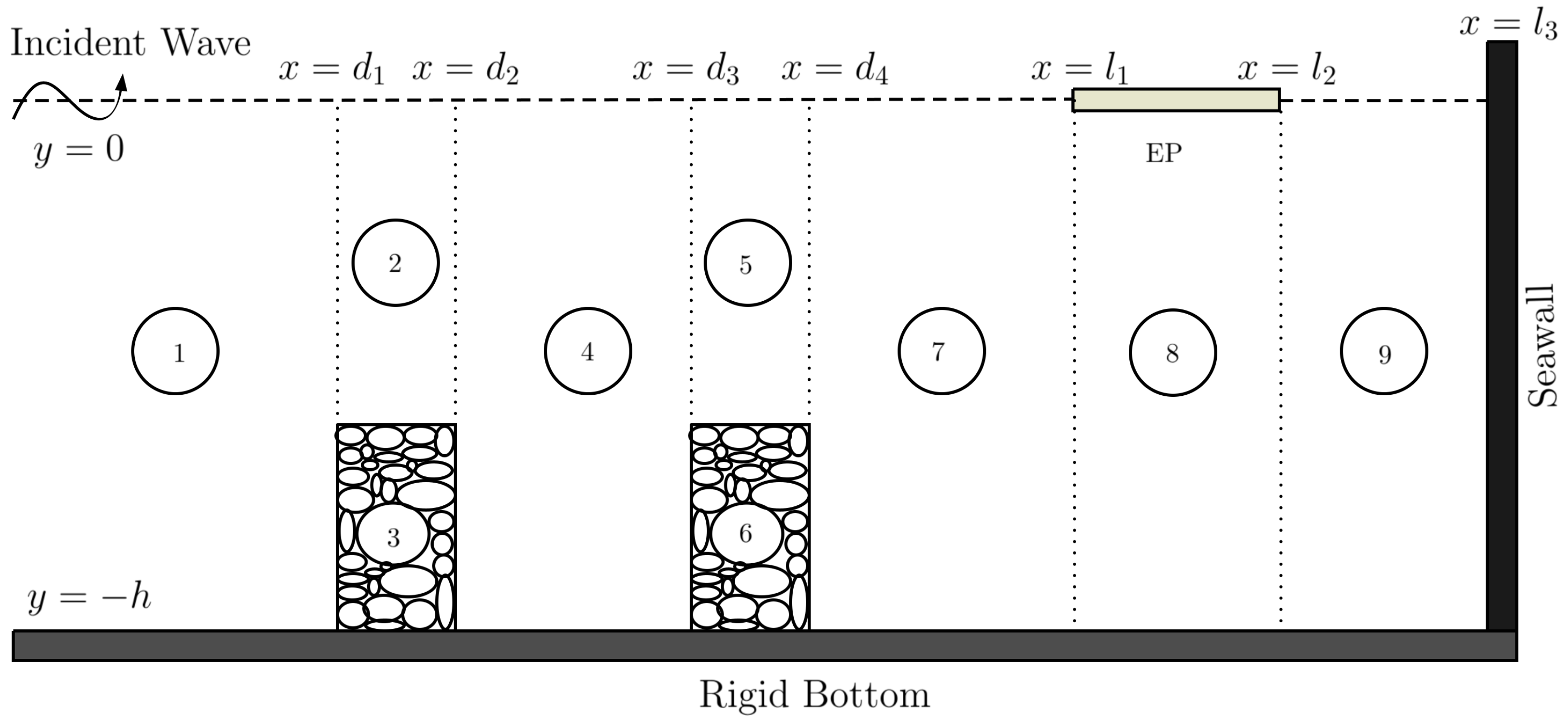
Figure 1. Schematic description of the physical model.
Mathematics 13 02733 g001
Figure 2. Validation of the numerical code by comparing with Koley et al. [15].
Mathematics 13 02733 g002
Figure 3. Variation of the wave force K w on the seawall with the width b 1 / h for different values of the frictional coefficient f 1 .
Mathematics 13 02733 g003
Figure 4. Variation of the wave force K w on the seawall with the gap L 1 / h for different values of the height a 1 / h .
Mathematics 13 02733 g004
Figure 5. Variation of the wave force K w on the seawall with the gap L 2 / h for different values of the height a 2 / h .
Mathematics 13 02733 g005
Figure 6. Variation of the wave force K w on the seawall with the width b 2 / h for different values of the porosity ϵ 2 .
Mathematics 13 02733 g006
Figure 7. Variation of the wave force K w on the seawall with respect to L 1 / h for two cases: (a) a single BSP with b 1 / h = 1 and (b) two BSPs with a combined width b 1 / h + b 2 / h = 1 .
Mathematics 13 02733 g007
Figure 8. Variation of the (a) wave reflection | R | and (b) wave dissipation K D with respect to wavenumber k 0 h for different values of frictional coefficient f 1 .
Mathematics 13 02733 g008
Figure 9. Variation of the (a) wave reflection | R | and (b) wave dissipation K D with respect to wavenumber k 0 h for different values of height a 2 / h of the second BSP.
Mathematics 13 02733 g009
Figure 10. Variation of the (a) wave reflection | R | and (b) wave dissipation K D with respect to L 2 / h for different values of a 1 / h .
Mathematics 13 02733 g010
Figure 11. Variation of the free surface elevation R e ( η 9 ) for different values of (a) ϵ 1 and (b) ϵ 2 .
Mathematics 13 02733 g011
Figure 12. Variation of the free surface elevation R e ( η 9 ) for different values of (a) a 1 / h and (b) a 2 / h .
Mathematics 13 02733 g012
Figure 13. Variation of the free surface elevation R e ( η 9 ) for different values of the flexural rigidity D / h 4 of an EP.
Mathematics 13 02733 g013
Figure 14. Free surface elevation Re ( η 9 ) for the case when (a) one BSP is present and (b) two BSPs are present.
Mathematics 13 02733 g014
Disclaimer/Publisher’s Note: The statements, opinions and data contained in all publications are solely those of the individual author(s) and contributor(s) and not of MDPI and/or the editor(s). MDPI and/or the editor(s) disclaim responsibility for any injury to people or property resulting from any ideas, methods, instructions or products referred to in the content.