Article

Entropy-Based Optimization of 3D-Printed Microchannels for Efficient Heat Dissipation

by
Felipe Lozano-Steinmetz
1,
Victor A. Martínez
1,
Carlos A. Zambra
2 and
Diego A. Vasco
1,*
1
Department of Mechanical Engineering, University of Santiago, USACH, Av. Bernardo O’Higgins 3363, Santiago 9170022, Chile
2
Department of Industrial Technologies, Faculty of Engineering, University of Talca, Camino a Los Niches km 1, Curicó 3640000, Chile
*
Author to whom correspondence should be addressed.
Mathematics 2025, 13(15), 2394; https://doi.org/10.3390/math13152394
Submission received: 17 June 2025 / Revised: 19 July 2025 / Accepted: 23 July 2025 / Published: 25 July 2025
(This article belongs to the Special Issue Computational Fluid Dynamics with Applications)

Abstract

Microchannel heat sinks (MCHSs) have emerged as an alternative for dissipating high heat rates. However, manufacturing MCHSs can be expensive, so exploring low-cost additive manufacturing using 3D printing is warranted. Before fabrication, the entropy minimization method helps to optimize MCHSs, enhancing their cooling capacity while maintaining their power consumption. We employed this method through computational simulation of laminar water flow in rectangular microchannels ( μ C) and minichannels (mC), considering two heat fluxes (10 and 50 kW/m2). The results showed that the frictional entropy is only appreciable in the smallest and largest channels. These computational results enabled the fabrication of the optimal μ C and mC, whose experimental implementation validated the computational findings. Moreover, we computationally studied the effect of using rGO-Ag water-based nanofluids as a coolant. In general, a reduction in total entropy generation was observed at a heat flux of 50 kW/m2. Although at lower heat flux (10 kW/m2), mC was the best option. Channels with lower heights were more effective at higher heat fluxes (≥50 kW/m2). Our findings offer a cost-effective strategy for fabricating high-performance cooling systems while also highlighting the interplay among heat flux, entropy generation, and nanofluid-enhanced cooling.

1. Introduction

During the last decade, the amount of data processed in data centers has increased dramatically, driven by the advent of technologies such as the Internet of Things, cryptocurrency mining, and cloud-based operations. In 2020, Science Magazine [1] reported that data centers consumed approximately 1% of global electricity, which was 6% higher than in 2010. Considering the recent introduction of artificial intelligence services to the market, it is reasonable to expect that this trend will continue, leading to intense demand for high-performance processors, including high-performance central processing units (CPUs), graphics processing units (GPUs), field-programmable gate arrays (FPGAs), and application-specific integrated circuit (ASIC) devices [2]. The increase in computing capacity typically results in a higher heat generation per unit volume, which must be efficiently dissipated to ensure optimal operation of electronic components and extend their useful life [3,4].
Conventional microchannel heat sink (MCHS) manufacturing techniques employ subtractive approaches, which involve removing excess material from a solid block to achieve the desired design. The removal of excess materials generates waste, which increases the cost of the finished product. The development of additive manufacturing (AM), pioneered by Kodama [5] and later refined through techniques such as fusion deposition modeling, has enabled the fabrication of complex geometries for MCHS applications. AM has become an innovative solution to the manufacturing challenges of MCHS due to its minimal dependence on variables such as material, dimensional accuracy, and internal and exterior complexity of the designed device [6]. Building components from powdered materials or filaments through AM minimizes waste and reduces material costs [7]. MCHS materials fall into three categories: metals and alloys (10–400 W/m K), ceramics (30–400 W/m K), and polymer nanocomposites (0.1–10 W/m K). Although polymers have lower thermal conductivity, they are lightweight and cost-effective, making them an attractive alternative [8]. However, their implementation in MCHS remains limited due to challenges such as high pressure drop, flow maldistribution, and manufacturing costs. Experimental studies have validated the effectiveness of heat sinks optimized for topology, designed to minimize pressure drop and thermal resistance, confirming the potential of AM in the fabrication of MCHS [9]. To optimize MCHS performance, it is crucial to balance heat transfer efficiency with pressure drop and pump power requirements. Studies, such as the research by Jung and Park using Al2O3 nanofluid, have demonstrated a reduction in entropy in MCHS [10].
The definition of the Nusselt number suggests that the cooling capacity of a device can be enhanced by reducing its characteristic length [11] or improving the thermal conductivity of the coolant. Tuckerman and Peace [12] dissipated 790 W/cm2, pumping water through a silicon-based microchannel heat sink with a hydraulic diameter of 85.8 μ m. Minichannels (1 mm ≤ D h ≤ 6 mm) and microchannels (10 μ m ≤ D h ≤ 1 mm) [13] have been widely applied in direct-to-chip liquid cooling due to their comparatively high thermal performance [7,14]. To address the limitations of coolant properties, several researchers have investigated the effect of uniformly dispersed nanomaterials (1–100 nm) in conventional coolants. The nanomaterial/liquid system, also known as a nanofluid, has consistently demonstrated superior thermal properties [15,16,17,18,19], which have led to its application in liquid cooling heat sinks. Jang et al. [20] experimentally utilized the improved thermal conductivity of nanofluids prepared with 1 vol.% of 2 nm diamond nanoparticles dispersed in water to improve the cooling performance of a silicon-based microchannel heat sink. Compared to water, the authors found that the thermal resistance of the heat sink decreased by 10%, resulting in a heat flux of 300 W/cm2 in both cases. Wu et al. [21] numerically studied the effect of using Al2O3/water nanofluid as coolant. Their research demonstrated that the reduction in thermal resistance is effective only when the pumping power is sufficient to overcome the increased viscous forces resulting from the addition of nanomaterials to water. The enhanced thermal performance achieved by the use of nanofluids comes at the cost of a higher pressure drop in the system, which consequently increases the entropy generation of the system. Menay et al. [22] experimentally quantify the generation of entropy due to heat transfer and pressure drop along bronze microchannels cooled by TiO2/water nanofluids. By comparing the total entropy generation of the cooling device using nanofluids and water as a coolant, the experimental data showed that nanofluids were only effective for the highest channel (H = 500 μ m) at Reynolds numbers less than 450.
The total entropy generation rate of a cooling system accounts for the thermal and hydraulic irreversibilities. The total entropy evaluates the thermodynamic advantage of a given heat transfer enhancement technique [23]. In a well-designed cooling system, the thermodynamic irreversibilities should be minimized as much as possible, which forms the basis of the entropy generation minimization method. Rastogi et al. [24] theoretically investigate the entropy generation rate in a circular microchannel cooled by a laminar water flow. They used constant heat flux as a boundary condition on the surface of the tube, finding that the entropy generation rate owing to heat conduction decreases as the tube diameter decreases, while the frictional entropy generation increases. Both contributions (thermal and hydraulic) reached the same magnitude for a 66.15 μ m pipe diameter. Furthermore, the authors theoretically demonstrated that the system’s heat load has a significant impact on the ideal diameter of the pipe.
Datta et al. [25] numerically studied the effect of including ribs in trapezoidal microchannels. The authors analyzed four different rib structures: rectangular, backward triangular, forward triangular, and diamond ribs. They found that incorporating ribs reduces the wall temperature. Although rectangular ribs showed the lowest wall temperature, the authors claimed that minimizing entropy generation is equivalent to maximizing thermal performance, provided a fixed power input is maintained. This led them to conclude that the use of diamond ribs within the cavities was the optimal solution. Using the total entropy generation rate as a criterion to optimize the trapezoidal microchannel heat sink, Yang et al. [26] numerically showed that incorporating CuO nanoparticles into water increases the entropy generation rate of the heat sink when only considering the viscous effects in the microchannels. Adio et al. [27] numerically studied the effect of using CuO/water nanofluid as a coolant in a multimanifold microchannel. Despite the apparent increase in the pressure drop resulting from the higher viscosity, the nanofluids performed thermodynamically better than water because they reduced the total entropy generation of the system. The CuO/water nanofluid resulted in attenuated temperature gradients within the fluid, leading to a greater decrease in thermal entropy generation compared to hydraulic entropy generation. Li et al. [28] reached a similar conclusion, finding that the entropy generation rate decreases with increasing fluid inlet temperature due to a reduction in the temperature gradient.
Despite efforts to optimize MCHS using computational tools, experimental results on the topic are scarce and necessary, and most available in the literature were obtained using expensive subtractive manufacturing techniques, such as electrical discharge machining, micro-milling, laser beam machining, and etching [29]. This study aims to use computational simulations prior to the fabrication of high-resolution, cost-effective MCHS using additive manufacturing with a photopolymer resin and to determine the maximum allowable heat flux to prevent excessive temperatures.
Specifically, computational simulations using water were performed to determine the maximum allowed heat flux within a Reynolds number range of 200 to 1200 by predicting the external surface temperature of the resin. Furthermore, the simulations identified the optimal channel height by minimizing the generation of entropy. The optimized designs were then manufactured using additive manufacturing (3D printing), and experimental tests were performed within a Reynolds number range of 200–600 to validate the computational results. The purpose of this study is to analyze the effect of channel height and Reynolds number, while considering only these two parameters, without taking into account other relevant factors, such as the channel cross-section and heat flux. Therefore, the analysis did not require advanced optimization methods.
Similar studies have implemented the direct metal laser sintering (DMLS) technique for fabricating MCHS using water as a coolant. In these works, the authors analyzed the effect of the Re number in the laminar regime using MCHS with hydraulic diameters of 500 ( μ m) [30] and 690 ( μ m) [31]. The problem with DMLS is that it produces rougher surfaces, making it difficult to control other geometric parameters [32]. In the present work, we present experimental results for hydraulic diameters of 666, 587, and 1000 μ C. Furthermore, the validated model provides the basis for a series of computational simulations using an aqueous-based nanofluid with reduced graphene oxide decorated with silver. Figure 1 illustrates the methodology of the work, which integrates two computational stages involving water and nanofluids, as well as an experimental stage that allows for the exploration of using a low-cost 3D printer to manufacture MCHS.

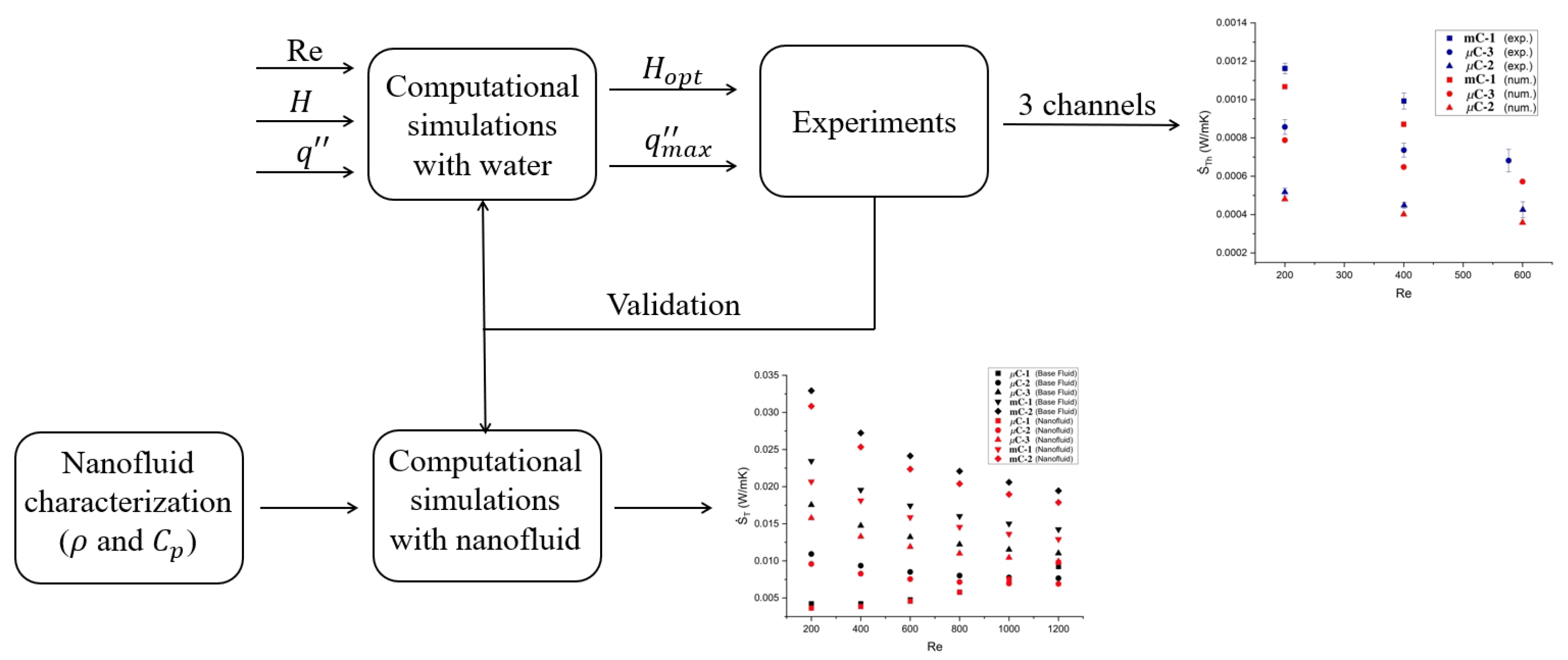
2. Computational Simulations

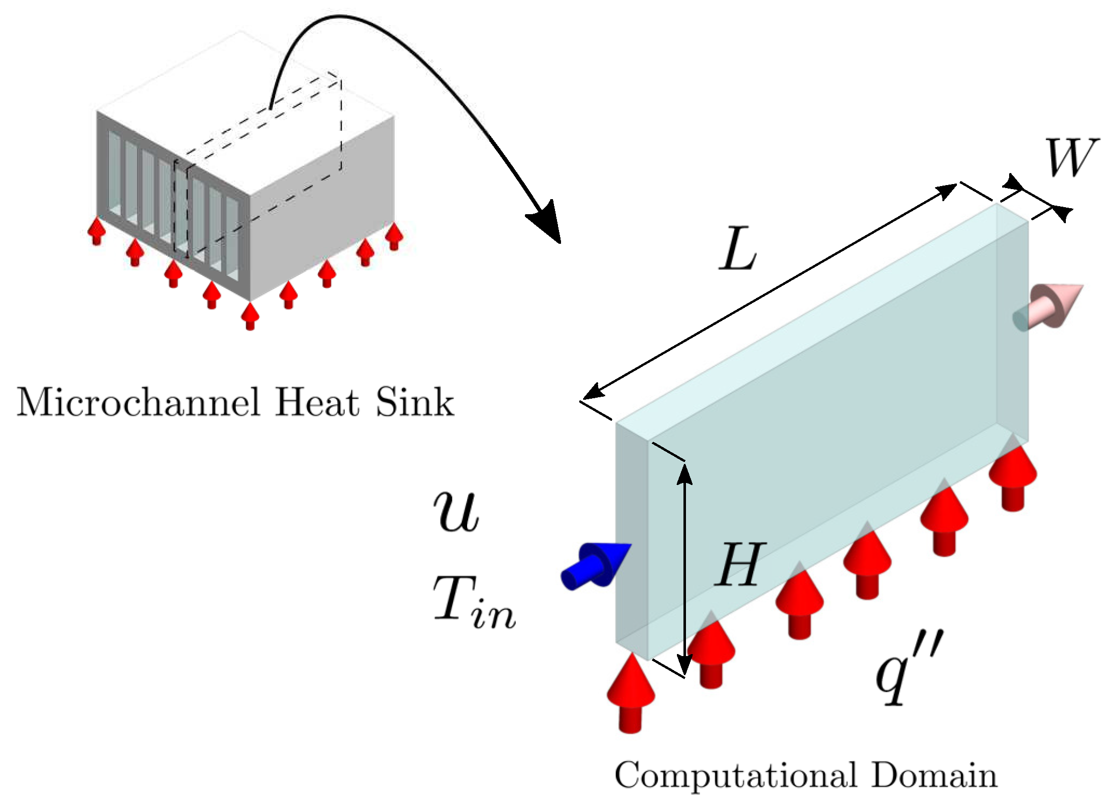
2.1. Computational Domain

Before manufacturing microchannel ( μ C) or minichannel (mC) heat sinks, eight rectangular cross-sectional channels were considered to computationally predict their entropy generation and explore the thermal limits of using 3D printed resin channels. The channels consisted of three μ Cs and five mCs. Figure 2 shows the physical situation in which an individual channel corresponds to the computational domain. Despite the simplicity of this computational domain, Chej et al. [33] demonstrated that for Re > 100, a simpler adiabatic model yields results very similar to those of conjugate models with convective and radiative boundary conditions. The width (W) and length (L) of the channels were kept constant for all cases: 1 mm and 50 mm, respectively. Table 1 shows the channels’ heights (H) considered for the optimization study.

2.2. Mathematical Model

2.2.1. Governing Equations

The coolant flow was modeled as a steady, laminar, incompressible single-phase flow with temperature-dependent thermophysical properties. The mathematical model governing the hydraulic and thermal processes corresponds to the equations of mass, momentum, and energy conservation (Equations (1)–(3)). Viscous dissipation effects are not considered, as they can be significant for fluids with low specific heat capacities and high viscosities, even in flows with relatively low Reynolds numbers and in microchannels with diameters smaller than 10 μ m. Moreover, in this case, the Brinkman number is very low (Br < 10 3 ) for the Reynolds number range studied and the heat dissipated [34].
( ρ · V ) = 0
V · ρ V + p ( μ V ) = 0
V · ( ρ C p ) T ( k T ) = 0

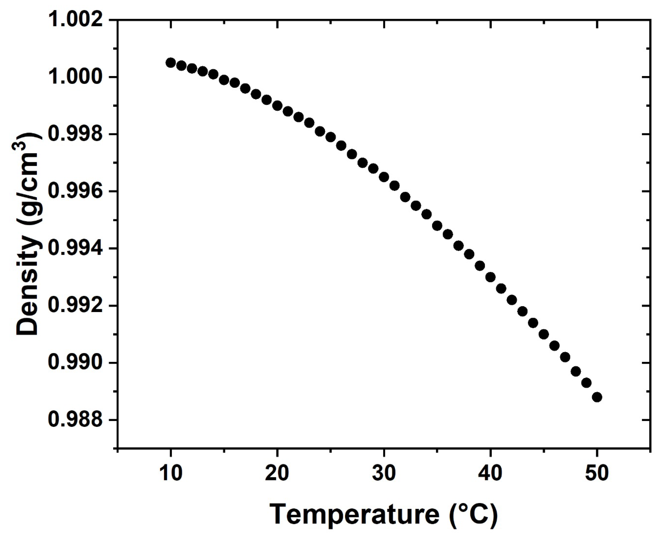
2.2.2. Thermal Properties

The thermal conductivity and dynamic viscosity of water were modeled using our experimental data, as reported by Lozano-Steinmetz et al. [35]. A linear function was used to model the thermal conductivity (Equation (4)), whereas a second-order polynomial function was used for viscosity (Equation (5)). Due to methodological considerations, the density and heat capacity were calculated using the equations proposed by Zografos et al. [36].
k = 2.0817 × 10 3 T + 6.6365 × 10 3 [ W / m K ]
μ = 2.979 × 10 7 T 2 1.9791 × 10 4 T + 3.3437 × 10 2 [ Pa   s ]
Since the study aims to predict how the addition of rGO-Ag nanoparticles to the coolant (water) affects the generation of thermal entropy and how the viscosity of the nanofluid influences the generation of frictional entropy, the nanofluid corresponds to rGO-Ag based on water with a concentration of 0.1 wt.%. The synthesis of this nanofluid is presented in the work of Lozano-Steinmetz et al. [35] in which the thermal conductivity and dynamic viscosity were measured (Equations (6) and (7)). In the present study, we used the same nanofluid whose density was measured with respect to temperature using an Anton-Parr (Graz, Austria) density meter model DMA 4101. Measurements were made in triplicate from 10 to 50 °C with steps of 1 °C (Figure 3). The equation that models the density of the nanofluid as a function of temperature is presented in Equation (8), with a coefficient of determination of R 2 = 0.9998 .
k n f = 3.0452 × 10 3 · T 0.14326 [ W / m     K ]
μ n f = 2.128 × 10 7 · T 2 1.4768 × 10 4 · T + 2.6092 × 10 2 [ Pa   s ]
ρ n f = 4.5 × 10 3 · T 2 0.0278 · T + 1001.3 [ kg / m 3 ]
The measured density of the nanofluids does not show significant differences from those obtained using the rule of mixtures (≤0.05%). Therefore, we assume that the mixture rule is valid for measuring the heat capacity, which requires the heat capacity of the base fluid and the nanoparticle [37]. Equation (9) allows us to determine the heat capacity for mixing ( C p m i x ).
C p m i x = ρ n p · C p n p · φ + ρ b f · C p b f · ( 1 φ ) ρ n p · φ + ρ b f · ( 1 φ )
The heat capacity of the base fluid ( C p b f ) is obtained using the equation of Zofragos et al. [36], the density of the base fluid ( ρ b f ), the density of the particle ( ρ n p ), considering a constant mass fraction ( φ ) at 0.1 wt.%, and for the heat capacity of the nanoparticles ( C p n p ), a test was carried out using a PerkinElmer (Shelton, CT, USA) DSC 4000. The DSC measurements were carried out in a temperature range of 10–50 °C with steps of 0.1 °C/min, performing two cycles of heating and cooling with 2 min rest at the maximum and minimum temperatures. The DSC test of the nanomaterial took 27 h. With all the properties obtained, we proceed to obtain Equation (10), which exhibits the behavior of the heat capacity of the nanofluid with respect to temperature.
C p n f = 1.785 × 10 7 · T 3 1.9149 × 10 4 · T 2 + 6.7953 × 10 2 · T 3.7559 [ kJ / kg     K ]
The thermal properties of the photosensitive resin (3D Printer UV Sensitive Resin) used to fabricate the channels were determined using a Decagon Devices KD2 Pro thermal properties analyzer, equipped with an SH-1 sensor. This probe enables measurement of the thermal conductivity, specific heat capacity, and thermal diffusivity of solid materials. To evaluate these thermal properties, a cylindrical sample was 3D-printed with dimensions of 5 cm in diameter and 15 cm in length. The thermal properties were measured ten times at ambient temperature, and the average values are shown in Table 2.

2.2.3. Boundary Conditions

Regarding the boundary conditions, the coolant flow enters the domain with an inlet temperature of 293.15 K and a constant Reynolds number (200 R e 1200). A constant heat flux of 10 and 50 kW/m2 was applied at the bottom of the channel, while the remaining walls were considered adiabatic ( 0 = T / y ). Finally, the non-slip condition was considered for all walls ( u = 0 ).

2.3. Numerical Parameters

Ansys Fluent® (2021 R2 Academic Multiphysics Campus Solution) was utilized to numerically solve the governing equations, employing the well-known SIMPLE algorithm, which is suitable for solving stable, nonlinear, coupled, conservative equations in this type of application [38]. The spatial discretization methods correspond to the last square cell-based for the gradients, second-order for the pressure, and QUICK for the convective terms of the momentum and energy equations. The numerical solution was considered to have converged once the residuals of the continuity, momentum, and energy equations were less than 1 × 10 4 , 1 × 10 6 , and 1 × 10 6 , respectively.

Grid Size Analysis and Validation

The computational domain was discretized using a structured grid of parallelepiped elements, with refinement toward the walls. The discretization was tested by performing a grid sensitivity analysis based on the average Nusselt number (Nu):
N u = q · D h k f ( T w T a v g )
In Equation (11), D h is the hydraulic diameter of the channel, T w is the temperature of the bottom wall of the channel, and T a v g is the bulk temperature of the coolant with thermal conductivity k f .
The grid independence study was conducted at a heat flux of 50 kW/m2 and an input Reynolds number of 600 for all channels. As an example, Table 3 displays the Nusselt number obtained for μ C-1. In this case, the selected grid yields a relative error of 3% compared to the previously tested grid. The grids used for the remaining channels are presented in Table 4.
To validate the numerical model, we have compared our results with the experimental data of Ho and Chen [39], Moraveji and Arddehali [40], and Uysal et al. [41], who studied a mC of the exact dimensions as our mC-2. Figure 4 shows that the trend described by the Nusselt number with respect to the Reynolds number is similar to that obtained by the authors mentioned above. The numerical results show an average relative error of 5.2% compared to the experimental data of Ho and Chen. Although the difference is not significant, it can be attributed to the neglect of the solid structure of the heat sink. By removing the conductive thermal resistances of the channel walls from the numerical analysis, the resulting convective heat transfer coefficient is slightly higher than the experimental data, which include the heat transfer mechanism related to the fin (or channel walls). Ho and Chen [39] utilized a copper-based heat sink, which justifies accounting for the fin’s efficiency in their data reduction. However, given the lower thermal conductivity of the 3D printing resin used in this study, the numerical optimization study focused only on thermal resistance to convection.

3. Materials and Methods

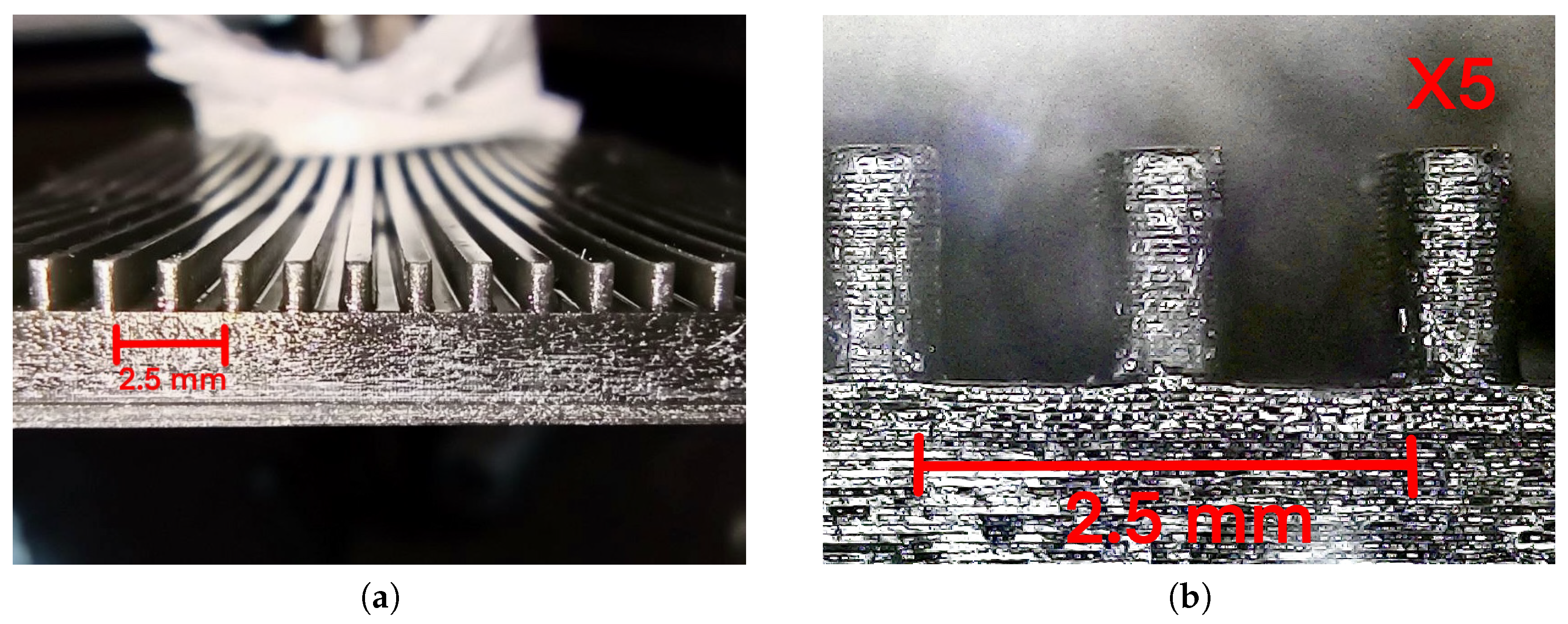
3.1. Heat Sink Manufacturing

The channels were manufactured using a photosensitive resin 3D printer, specifically a Creality LD-002R printer (Shenzhen, China), and LCD resin of the same brand. Unlike filament 3D printing (PLA), this process utilizes an ultraviolet screen to harden the resin layer by layer, with an adequate resolution for the application (75 μ m XY that defines the smallest reproducible detail in the horizontal plane and 20 μ m Z, which determines the layer thickness that affects vertical smoothness), at a speed of 20 mm/h and a nominal power of 72 W. The procedure began with calibrating the printing platform, ensuring its correct alignment with the LCD screen through manual adjustments and the use of a sheet of paper as a reference. Subsequently, the resin was poured into the printing container, ensuring safety measures. Then, the printing file was loaded and the manufacturing process was started, which was carried out in a ventilated environment due to the emission of gases. Once the printing was finished, the piece was carefully removed from the platform with a metal spatula, and excess resin was removed by cleaning with isopropyl alcohol. This process enabled the precise manufacturing of the channels, ensuring their correct geometry and surface quality. Photosensitive resin 3D printing yields good results on a small scale, offering a surface finish superior to other additive manufacturing (AM) methods, as illustrated in Figure 5a. The fabricated channels correspond to μ C-2, μ C-3, and mC-1. These channels minimize the entropy generation for the analyzed heat fluxes, as shown in the computational simulations carried out with water as coolant. Multiple parallel channels with walls 0.5 mm thick were constructed, as shown in Figure 5b.
In addition, the heat sinks were tested at 200 °C, 150 °C, and 100 °C in an oven for 20 min. The results showed that the integrity of the channels was not affected at a temperature of 100 °C, which is in line with the operating temperature of a CPU [42].

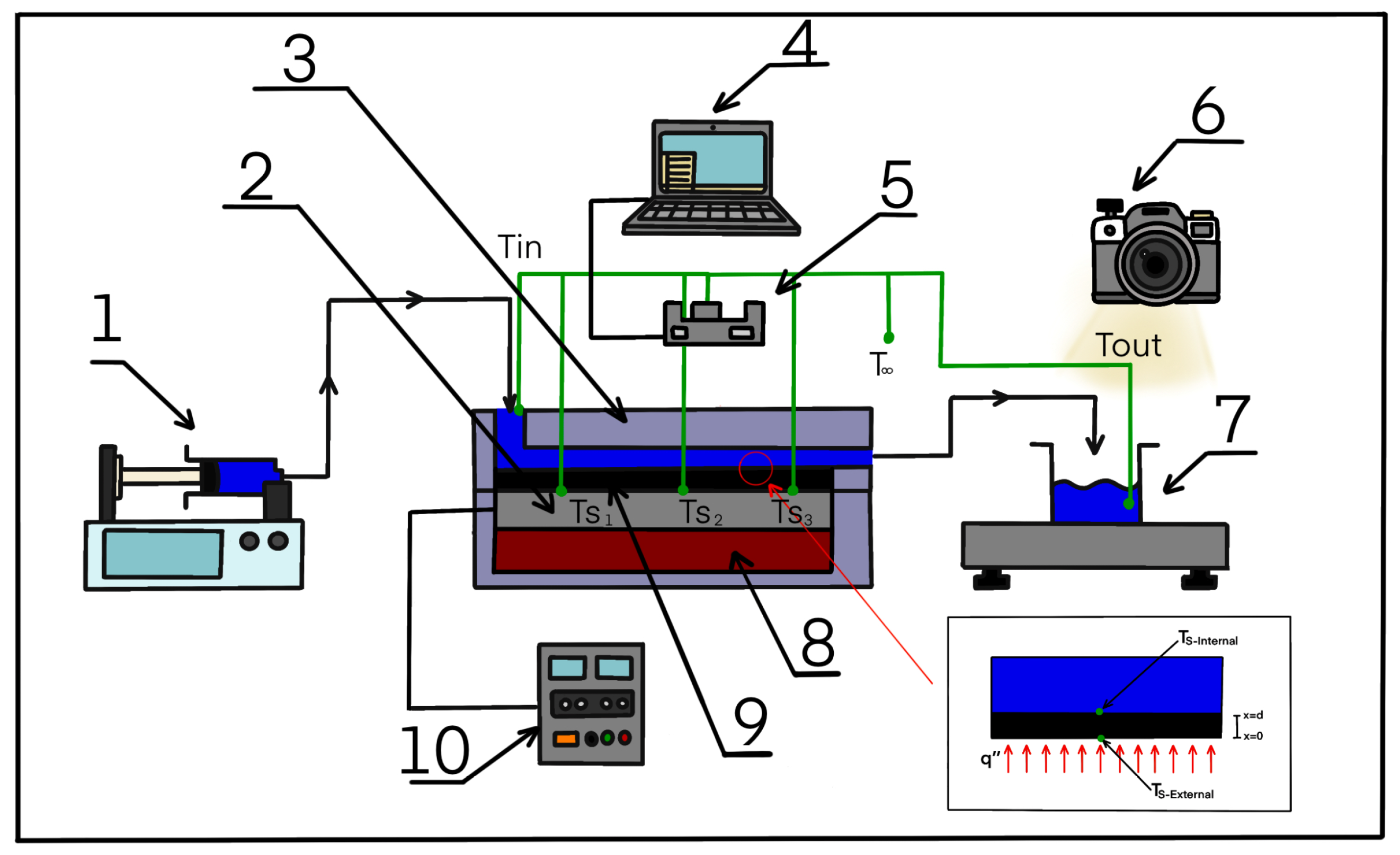
3.2. Experimental Setup

A high-temperature polybutylene channel containment system was designed to test the fabricated channels. The containment system consists of two parts. The upper part contains the channels and has two 4 mm holes through which the coolant (water) is pumped. The lower part includes electrical resistors, thermocouples, and thermal insulation that reduces heat losses. The lower part of the containment system has three outputs to connect the cables to the power supply (Mastech, Taipei, Taiwan, HY3005) and the thermocouples to the DAQ data acquisition system (National Instruments, Austin, TX, USA, NI CDAQ-9174). Figure 6 shows the experimental setup, which has a Progetti (Trofarello, Italy) model PG-907s syringe pump with a generic 60 mL syringe (1) to supply fluid to channels (9) at a constant flow rate. The liquid flows through hoses connected to the channel containment system (3) using nipples. The lower part of the containment system has three PTC resistors of 2 × 3 cm (2) connected to an adjustable power source (10) to control the heat flow. The resistors are above the thermal insulation of high-temperature silicone (8).
In this work, the coolant flows through the channels at a constant flow rate, and the inlet, outlet, and surface temperatures are obtained when the channel can dissipate 10 kW/m2. To ensure repeatability, each experimental test was performed in triplicate, and the error bars correspond to the standard deviation.
The manufactured channels dissipate up to 10 kW/m2, avoiding their overheating and structural failure. The heat flow dissipated by the channels was quantified by performing an energy balance between the inlet ( i n ) and outlet ( o u t ) of the system (Equation (12)), where m ˙ w and C p , w are the mass flow rate and the heat capacity of water, respectively.
q = m ˙ w · C p , w · ( T o u t T i n )
The wall temperature used to determine the convective heat transfer coefficient and the Nusselt number was defined as the inner surface temperature of the channels ( T s , i n ), which was not directly measured; however, the outer surface temperature was measured ( T s , o u t ). The inner surface temperature required the solution (Equation (13)) of the heat conduction equation. Figure 6 represents the physical situation of the conduction problem, where the blue surface represents the water flowing through the channels, and the black surface represents the bottom wall of the channel of thickness d and thermal conductivity k r e s .
T s , i n = q k r e s · d + T s , o u t

4. Results and Discussion

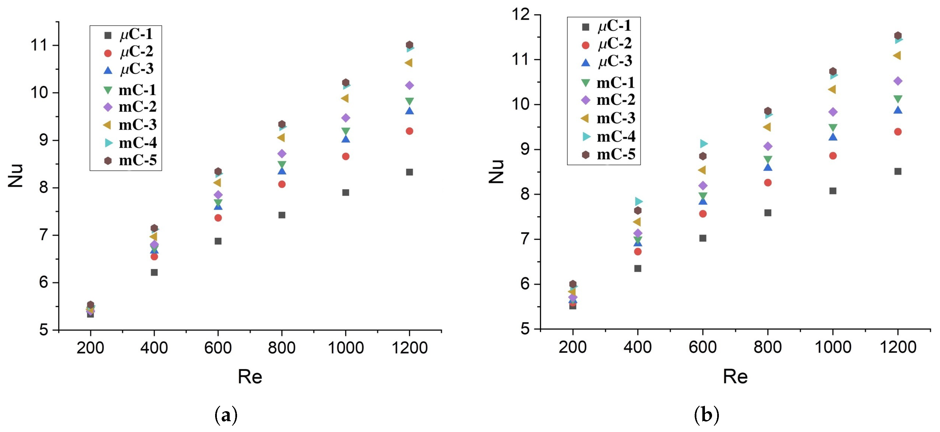
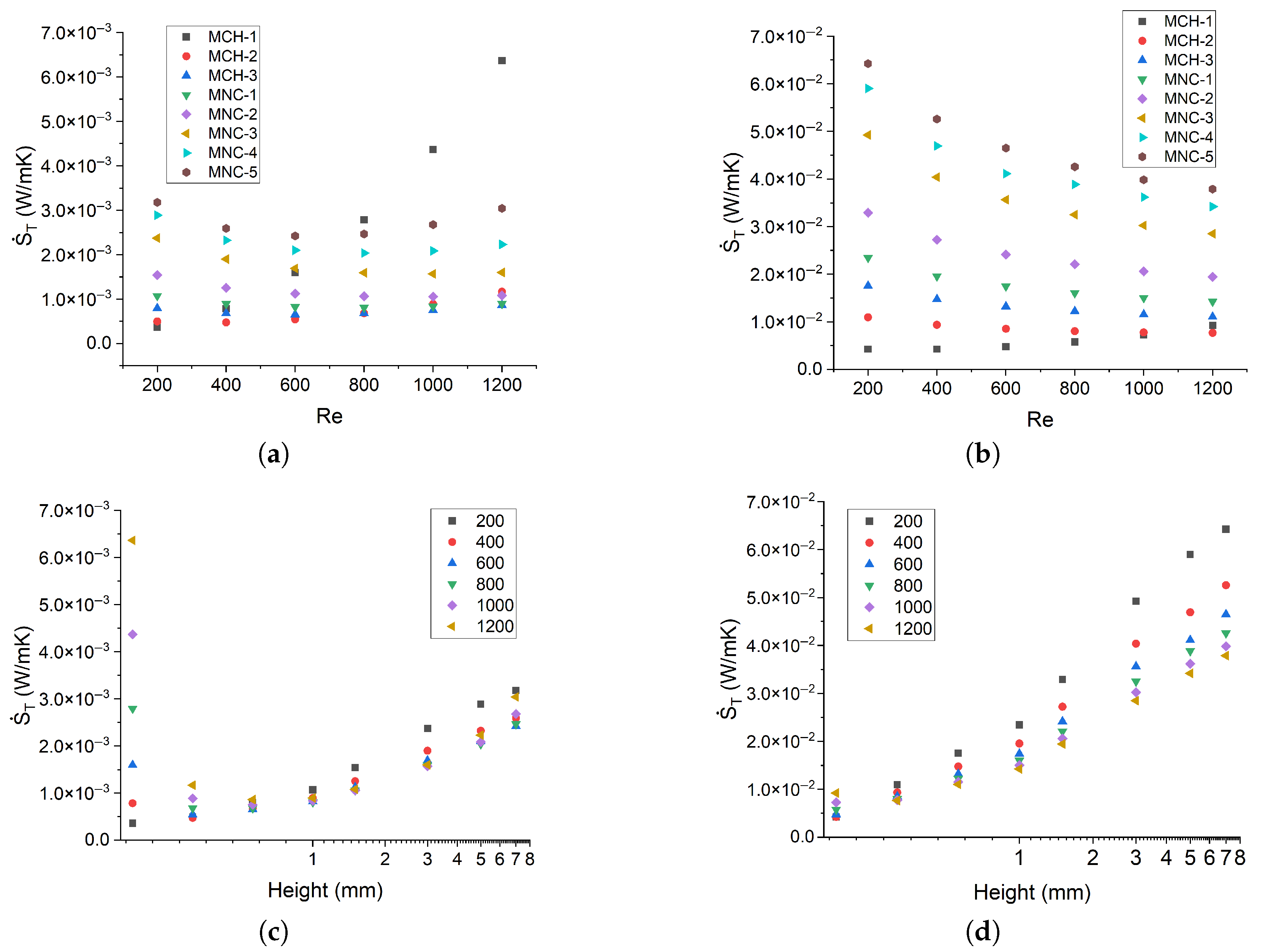
4.1. Computational Results with Water

The behavior of the Nusselt number is essential for correctly selecting the channel height in heat removal systems, as it is a fundamental parameter in determining both thermal and total entropy generation. The Nusselt number exhibits a strictly increasing relationship with the Reynolds number, regardless of heat flux, as illustrated in Figure 7. When comparing the smallest channel ( μ C-1) with the largest channel (mC-5), for Re = 200, it can be observed that there is a difference of 3.78% and 8.82% for heat fluxes of 10 and 50 kW/m2, respectively. However, for Re = 1200, such differences are greater (approximately 34%). These results indicate that as the Reynolds number increases, the Nusselt number becomes more sensitive to the channel height, exhibiting an inverse relationship with this parameter. At a Reynolds number of 200, the coolant reaches a thermally saturated state, indicating that it has absorbed nearly all the heat it can, as evidenced by an outlet temperature approaching that of the heated wall. Under these conditions, geometric modifications, such as increasing the channel height, have a minimal impact on thermal performance. In contrast, at higher Reynolds numbers, the coolant retains greater thermal capacity, and thus, variations in channel geometry, such as height, continue to influence heat transfer effectiveness.
Using the expressions for the generation of entropy proposed by Bejan [43,44], we have obtained the total generation of entropy of the system (Equation (14)), which consists of two terms: the generation of frictional entropy (Equation (15)) and thermal entropy (Equation (16)).
S ˙ T = S ˙ f r + S ˙ T h
S ˙ f r = 8 · m ˙ 3 · f π · ρ 2 · T w · D h 5
S ˙ T h = q 2 · π · D h 2 k · T w 2 · N u
The generation of frictional entropy, shown in Figure 8a,b, follows the same trend for both heat fluxes (10 and 50 kW/m2). To analyze the influence of Reynolds number on frictional entropy generation, μ C-1, mC-1, and mC-5 channels are studied for Re = 200 and Re = 1200. The differences between the two Re correspond to 6.06, 0.289, and 1.38 mW/(mK), respectively, for a heat flux of 10 kW/m2. As expected, these differences are similar for a heat flux of 50 kW/m2, being 6.33, 0.277, and 1.33 mW/(m K). Hence, the hydraulic irreversibilities experienced by the system increase with the Reynolds number, especially for μ C-1, whose lower hydraulic diameter leads to higher friction coefficients.
Figure 8c,d show the generation of frictional entropy with respect to the height of the channels μ C-3, mC-1, mC-2, and mC-3, as they have the lowest generation of frictional entropy. The numerical results indicate that a channel height of 1.5 mm (mC-2) minimizes frictional entropy generation, regardless of the heat input. Moreover, the optimal channel height is independent of the Reynolds number. A similar trend of entropy generation with respect to channel height has been observed in other studies, but for different aspect ratios H/W [45].
Figure 9 shows the thermal entropy generation in relation to the Reynolds number, where a decreasing trend can be observed for both heat fluxes. The channels μ C-1, mC-1, and mC-5 exhibit differences of 53.03%, 76.84%, and 92.64%, respectively, between Re = 200 and Re = 1200 under a heat flux of 10 kW/m2. However, for a heat flux of 50 kW/m2, the differences for the same channels drop to 48.88%, 67.82%, and 75.81%, respectively. Although the trend is similar, there are significant differences between the results because higher heat fluxes increase the irreversibilities and the thermal entropy generation.
Regarding total entropy generation, it can be observed that there are differences of one order of magnitude when the heat flux increases from 10 to 50 kW/m2 (Figure 10a,b). At a heat flux of 10 kW/m2, the smallest microchannel ( μ C-1) generates the highest total entropy at Re = 1200, which is mainly due to the higher contribution of hydraulic irreversibilities. The microchannels μ C-2 and μ C-3 exhibit the same behavior, showing that on the microscale, the contribution of frictional entropy generation is as significant as the thermal contribution, especially at low heat fluxes. In the case of intermediate-size channels (mC-1 and mC-2), the total entropy generation is practically equal to the thermal entropy generation since the contribution of frictional entropy is lower than 1%, which is also observed for larger minichannels (mC-3, mC-4, and mC-5). For a heat flux of 50 kW/m2, frictional entropy generation contributes less than 5% to the total entropy generation. Consequently, each channel under study has a Reynolds number that minimizes entropy generation. Table 5 presents the magnitude of the Reynolds number that minimizes total entropy generation for each channel, which is obtained by applying a second-degree polynomial fit to each data set.
Figure 10c,d show the total entropy generation with respect to channel height on a logarithmic scale. For a heat flux of 10 kW/m2, the smallest microchannel ( μ C-1) presents an entropy generation highly influenced by the Reynolds number. This behavior confirms previous observations, as the total entropy generation of μ C-1 is significantly driven by hydraulic irreversibilities due to its lower hydraulic diameter. However, this influence disappears as the heat input increases, and the total entropy generation becomes thermally driven. Therefore, μ C-1 was discarded as an option for low heat fluxes.
For the heat flux of 10 kW/m2, μ C-3 and mC-1 present the lowest entropy generation, showing the same order of magnitude for each of the Reynolds numbers due to the low influence of the frictional entropy. The differences between Re = 200 and Re = 1200 for μ C-3 and mC-1 channels correspond to 8.60% and 16.32%, respectively. Although μ C-3 minimizes the total entropy generation, the total entropy generation of mC-1 was only 3.82% higher on average. Considering cooling performance and manufacturability, mC-1 remains a valid alternative for applications with heat fluxes lower than 10 kW/m2.

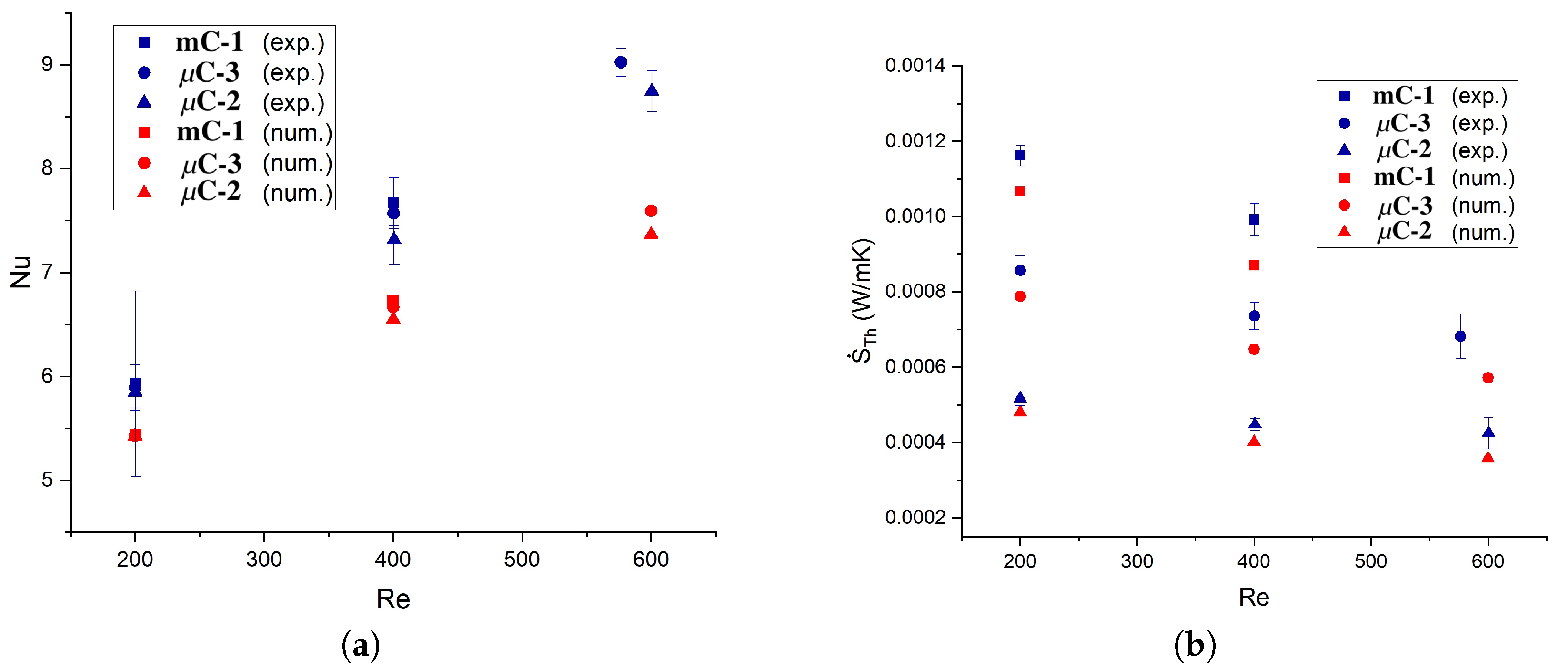
4.2. Experimental Results

Due to limitations of the syringe pump, the experimental study was conducted in Reynolds numbers ranging from 200 to 600, and each condition was tested three times. Consequently, the uncertainty associated with each data point is represented by the corresponding standard deviation.
Figure 11a shows the experimental and numerical results of the Nusselt number for channels mC-1, μ C-3, and μ C-2. It can be observed that there is an increasing discrepancy between the numerical and experimental results regarding the Reynolds number. For Re = 200, there is an average difference of approximately 8.5% between the numerical and experimental results, increasing to 13% and 18.7% for Re = 400 and Re = 600, respectively. The thermal entropy generation shows differences of the same magnitude as those presented by the Nusselt number. Figure 11b presents the experimental and numerical results of thermal entropy generation for the minichannel mC-1 and the microchannels μ C-3, μ C-2. The percentage differences between the numerical and experimental results may indicate that some aspects were not adequately considered during the simulations, especially at higher Reynolds numbers. For example, viscous dissipation was not included in our mathematical model, while in other numerical works [46] with microchannels, the viscous dissipation term has been included. Koo and Kleinstreuer [34] compared the magnitudes of each term that governs the thermal energy equation and found that the viscous dissipation effect increases as the channel size decreases. Therefore, for smaller microchannels, this effect may be a consideration.
The agreement between the experimental and numerical results is susceptible to the temperature difference between the inner wall of the channel and the fluid, which is crucial to obtaining the convective heat transfer coefficient. As the Reynolds number increases, the wall temperature decreases, approaching the bulk temperature of the fluid at the inlet. This temperature difference decreases significantly, making the experimental determination of the heat transfer coefficient more sensitive to experimental uncertainty, as it is closely related to this temperature difference.

4.3. Computational Results with Nanofluid

Based on the minimization of the total entropy generation experimentally determined, the channels μ C-1, μ C-2, μ C-3, mC-1, and mC-2 were selected to perform the numerical study with nanofluids. The physical situation is shown in Figure 2, with heat fluxes of 10 and 50 kW/m2 for Reynolds numbers ranging from 200 to 1200.
The temperature of the wall is crucial to determine the convective heat transfer coefficient and the generation of entropy. As shown in Figure 12, when comparing the nanofluid with the base fluid at a heat flux of 10 kW/m2, only minor differences (0.05 to 0.2%) were observed. No significant influence of the working fluid can be reported, which is especially true for μ C-1, where the effect on the wall temperature is not greater than 1 K. For a heat flux of 50 kW/m2, there is also no considerable influence when changing the working fluid, with percentage differences ranging from 0.25% to 0.32%.
Figure 13a,b show the behavior of the convective heat transfer coefficient in relation to the Reynolds number for both working fluids. For a heat flux of 10 kW/m2, there is an increase from 16.86% to 21.42%. The highest improvement is registered by μ C-1 at Re = 200, while mC-2 shows the lowest improvement. For a heat flux of 50 kW/m2, the increase is lower, from 7.25% to 19.41%. Channel μ C-1 exhibits the maximum difference and mC-2 the lowest. Therefore, the channel height has a significant impact on the convective heat transfer coefficient, which is particularly critical for nanofluids in smaller channels.
Nanofluids enhance heat transport by introducing heat carriers (nanomaterials) that are evenly dispersed within the base fluid, which improves their thermal conductivity. Since the heat transfer coefficient is a direct measure of the intensity of the temperature gradient near the surface, a fluid with higher thermal conductivity is expected to reduce the temperature difference between the surface and the bulk fluid by efficiently transporting heat into the coolant. This interplay between enhanced thermal conductivity and reduced temperature gradients results in higher heat transfer coefficients for nanofluids. The effect is more intense in smaller channels, where the ratio of liquid in contact with the solid structure is greater relative to the total fluid volume in the cooling system.
Figure 13c,d show the behavior of the Nusselt number with respect to the Reynolds number. At a heat flux of 10 kW/m2, the Nusselt number decreases from 1.17 to 5.9% regarding the base fluid, which is more pronounced for larger channels and higher Reynolds numbers. By interpreting the Nusselt number as
N u = h D h k f = D h / k f A 1 / h A = Conductive Thermal Resistance Convective Thermal Resistance
The decrease in this parameter observed when using nanofluids can be interpreted as a significant reduction in the conductive thermal resistance of the process. This is attributed to the higher thermal conductivity of the nanofluids, which is 28% greater than that of the base fluid. At a heat flux of 50 kW/m2, the Nusselt number decreases by 4.75 to 15.11%, with the nanofluid showing greater enhancement than the base fluid, particularly at higher channel heights and higher Reynolds numbers.
Figure 14a,b show the influence of nanofluids on the generation of thermal entropy. A positive behavior is observed that supports the use of nanofluids as a working fluid. For a heat flux of 10 kW/m2, the nanofluid decreases the thermal entropy generation by 14 to 17% because the heat convection increases and the irreversibilities associated with the thermal section decrease. Concerning a heat flux of 50 kW/m2, the use of nanofluid decreases the generation of thermal entropy by 8 to 15%, which is more relevant for larger channels.
Other authors have noticed that nanofluids minimize entropy generation at lower Reynolds numbers [28], especially compared to other coolants (air and ammonia) [47]. The addition of nanoparticles significantly decreases the generation of thermal entropy [48], but according to other authors [27,49,50], the frictional entropy increases slightly with the addition of nanoparticles. Manay et al. [22] experimentally studied the effect of aqueous nanofluids with TiO2 nanoparticles. They found a similar decreasing trend of thermal entropy with the Reynolds number 100–750 for different concentrations of nanoparticles and microchannel heat sink heights, but values one order of magnitude higher than ours. Adio et al. [51] numerically studied an interrupted microchannel heat sink with rib turbulators using Al2O3–water nanofluids. The authors observed a similar trend in thermal entropy within a comparable range of Reynolds numbers (100–700).
Figure 14c,d show the frictional entropy generation as a function of Reynolds number. For the case modeled with a heat flux of 10 kW/m2 and using nanofluids as coolant, frictional entropy generation increases from 39.14% to 62.3%. Similarly, at 50 kW/m2, it rises from 0.70% to 30.11% when nanofluids are used in the smaller channels. Regardless of the heat flux, this increase is more pronounced at lower Reynolds numbers. Since nanoparticles contribute to increased viscosity, the resulting hydraulic irreversibilities also rise, as they are directly influenced by viscosity through shear stress. Adio et al. [51] and Manay et al. [22] reported a similar trend with Reynolds number, although their values were up to two orders of magnitude higher than ours due to the use of lower channel heights (200–500 μ m). The behavior of both thermal and frictional entropy generation exhibits the same trend, regardless of the configuration and geometry of the MCHS [52,53,54].
Finally, the focus is on the total entropy generation of the system that corresponds to the sum of both components. The total entropy allows us to know if heat transfer improvements are higher when using nanofluids or if the frictional entropy overshadows them due to the increase in viscosity. For a heat flow of 10 kW/m2, the behavior of the nanofluid with respect to the base fluid with μ C-1, an increase in entropy generation is observed, obtaining increases from 19 to 45.73% for Re = 200 and 1200, respectively. The generation of frictional entropy dulls the improvements obtained by the thermal component. For microchannels μ C-2 and μ C-3 at low Reynolds, a decrease in entropy generation is obtained (14.51 to 4.79%). In contrast, for high Reynolds, frictional entropy generation dominates thermal entropy, obtaining an increase in entropy generation of 26.05 and 11.38% for μ C-2 and μ C-3 at Re = 1200, respectively. For mC-1 and mC-2, nanofluids are recommended, since they decrease the total entropy generation of the system in the range of 2.27–14.06%.
On the other hand, with a heat flux of 50 kW/m2 in μ C-1, an increase in entropy generation is observed at high Reynolds numbers, obtaining increases of 6.19% for Re = 1200. At the same time, at low Reynolds numbers (200–600), there is a decrease in entropy generation from 14.20% to 3.97%. For the rest of the microchannels, there is a decrease in entropy generation at each Reynolds number, decreasing from 12.25% to 8.07%. Therefore, nanofluids are recommended for most microchannels and all minichannels studied, as shown in Figure 14e,f. Rastogi and Mahulikar [24] performed an analytical study, obtaining the total entropy for circular MCHS. For a channel of 1000 μ m, a heat flux of 100 kW/m2, and a Peclet number of 1490, the authors found a total generation of entropy of 10.281 mW/mK. For comparison, for an MCHS with a hydraulic diameter of 1000 μ m and a heat flux of 50 kW/m2, generation of entropy values in the range of 15 and 25 mW/m · K, and specifically values in the range of 20–23 mW/m · K for a Peclet number of approximately 1200. It is essential to note that as the channel height increases, the total entropy also increases. However, other authors [55] found an opposite tendency for water and different nanofluids based on metallic oxides.

5. Conclusions

Through 3D printing using photosensitive resin, mini-channels can be fabricated that are capable of removing heat rates of up to 10 kW/m2. This technique is accessible, affordable, and promising for the future of testing new nanofluids for heat dissipation.
The results allowed us to conclude that there is no optimal height that minimizes entropy generation for either of the two heat flows. Furthermore, according to the principle of entropy generation, for larger heat flows (>10 kW/m2), microchannels with smaller hydraulic diameters are required. However, special care must be taken when reducing the height of the microchannels, as the generation of frictional entropy becomes very relevant in small microchannels due to the increase in the friction factor.
The required work for transporting the fluid is even greater when a nanofluid is used as a coolant. Still, when high heat rates must be removed, thermal entropy overshadows frictional entropy. Nanofluids based on rGO-Ag are a great option, as they decrease the total entropy generation of the system by up to 12%.
The use of resin-based 3D printing for the fabrication of heat sinks provides a cost-effective and adaptable method to test a wide range of geometries and dimensions, significantly supporting experimental research in microchannel and minichannel applications. This approach enables rapid prototyping and design iteration, which can directly contribute to the optimization of real thermal management devices, especially during the early stages of development.
However, the mechanical stability of the printed channels must be carefully evaluated under operational heat fluxes. For applications involving heat fluxes exceeding 50 kW/m2, the use of higher temperature-resistant printing materials is recommended to maintain structural integrity and performance.
Future work may focus on the integration of advanced polymers or composite materials to expand the thermal limits of printed components. Furthermore, validating these 3D-printed prototypes under real operating conditions with nanofluids and scaling up to full-size device implementations will further bridge the gap between experimental research and practical engineering applications.

Author Contributions

Conceptualization, D.A.V. and F.L.-S.; methodology, F.L.-S.; validation, F.L.-S., D.A.V. and V.A.M.; formal analysis, F.L.-S., D.A.V. and V.A.M.; investigation, F.L.-S.; resources, D.A.V. and C.A.Z.; data curation, F.L.-S. and V.A.M.; writing—original draft preparation, F.L.-S.; writing—review and editing, V.A.M., D.A.V. and C.A.Z.; visualization, F.L.-S.; supervision, D.A.V. and C.A.Z.; project administration, D.A.V. and C.A.Z.; funding acquisition, D.A.V. and C.A.Z. All authors have read and agreed to the published version of the manuscript.

Funding

This research was funded by Fondecyt 1251661 project of the National Research and Development Agency of Chile (ANID) and DICYT project, Código 052316VC-Ayudante, Vicerrectoría de Investigación, Desarrollo e Innovación, Universidad de Santiago de Chile.

Data Availability Statement

The data presented in this study are available upon request from the corresponding author, as we are still in the process of organizing a public repository.

Conflicts of Interest

The authors declare no conflicts of interest.

References

  1. Masanet, E.; Shehabi, A.; Lei, N.; Smith, S.; Koomey, J. Recalibrating global data center energy-use estimates. Science 2020, 367, 984–986. [Google Scholar] [CrossRef] [PubMed]
  2. Heydari, A.; Gharaibeh, A.R.; Tradat, M.; Soud, Q.; Manaserh, Y.; Radmard, V.; Eslami, B.; Rodriguez, J.; Sammakia, B. Experimental evaluation of direct-to-chip cold plate liquid cooling for high-heat-density data centers. Appl. Therm. Eng. 2024, 239, 122122. [Google Scholar] [CrossRef]
  3. Lee, J.; Mudawar, I. Fluid flow and heat transfer characteristics of low temperature two-phase micro-channel heat sinks–Part 1: Experimental methods and flow visualization results. Int. J. Heat Mass Transf. 2008, 51, 4315–4326. [Google Scholar] [CrossRef]
  4. Reece, D.; Huss, R. The Standard Electronic Modules Program. IEEE Trans. Compon. Hybrids Manuf. Technol. 1979, 2, 491–499. [Google Scholar] [CrossRef]
  5. Kodama, H. Automatic method for fabricating a three-dimensional plastic model with photo-hardening polymer. Rev. Sci. Instrum. 1981, 52, 1770–1773. [Google Scholar] [CrossRef]
  6. Kivanani, A.N.; Khalilpourazary, S.; Mobadersani, F. Additive manufacturing for producing microchannel heat sinks. Prog. Addit. Manuf. 2025, 10, 231–245. [Google Scholar] [CrossRef]
  7. Tiwari, R.; Andhare, R.S.; Shooshtari, A.; Ohadi, M. Development of an additive manufacturing-enabled compact manifold microchannel heat exchanger. Appl. Therm. Eng. 2019, 147, 781–788. [Google Scholar] [CrossRef]
  8. Shah, A.K.; Li, H.; Xin, Z.; Wu, Z. A Review on Additive Manufacturing of Topology Optimized Microchannel Heat Sink. Heat Transf. Eng. 2025, 1–27. [Google Scholar] [CrossRef]
  9. Ozguc, S.; Teague, T.F.; Pan, L.; Weibel, J.A. Experimental study of topology optimized, additively manufactured microchannel heat sinks designed using a homogenization approach. Int. J. Heat Mass Transf. 2023, 209, 124108. [Google Scholar] [CrossRef]
  10. Jung, S.Y.; Park, H. Experimental investigation of heat transfer of Al2O3 nanofluid in a microchannel heat sink. Int. J. Heat Mass Transf. 2021, 179, 121729. [Google Scholar] [CrossRef]
  11. Darvanjooghi, M.H.K.; Esfahany, M.N. Experimental investigation of the effect of nanoparticle size on thermal conductivity of in-situ prepared silica–ethanol nanofluid. Int. Commun. Heat Mass Transf. 2016, 77, 148–154. [Google Scholar] [CrossRef]
  12. Tuckerman, D.B.; Pease, R.F.W. High-performance heat sinking for VLSI. IEEE Electron Device Lett. 1981, 2, 126–129. [Google Scholar] [CrossRef]
  13. Mehendale, S.S.; Jacobi, A.M.; Shah, R.K. Fluid Flow and Heat Transfer at Micro- and Meso-Scales with Application to Heat Exchanger Design. Appl. Mech. Rev. 2000, 53, 175–193. [Google Scholar] [CrossRef]
  14. Kandlikar, S.G.; Grande, W.J. Evolution of microchannel flow passages–thermohydraulic performance and fabrication technology. Heat Transf. Eng. 2003, 24, 3–17. [Google Scholar] [CrossRef]
  15. Toghraie, D.; Chaharsoghi, V.A.; Afrand, M. Measurement of thermal conductivity of ZnO–TiO2/EG hybrid nanofluid: Effects of temperature and nanoparticles concentration. J. Therm. Anal. Calorim. 2016, 125, 527–535. [Google Scholar] [CrossRef]
  16. Zadkhast, M.; Toghraie, D.; Karimipour, A. Developing a new correlation to estimate the thermal conductivity of MWCNT-CuO/water hybrid nanofluid via an experimental investigation. J. Therm. Anal. Calorim. 2017, 129, 859–867. [Google Scholar] [CrossRef]
  17. Mintsa, H.A.; Roy, G.; Nguyen, C.T.; Doucet, D. New temperature dependent thermal conductivity data for water-based nanofluids. Int. J. Therm. Sci. 2009, 48, 363–371. [Google Scholar] [CrossRef]
  18. Beck, M.P.; Yuan, Y.; Warrier, P.; Teja, A.S. The thermal conductivity of aqueous nanofluids containing ceria nanoparticles. J. Appl. Phys. 2010, 107, 066101. [Google Scholar] [CrossRef]
  19. Lee, J.H.; Hwang, K.S.; Jang, S.P.; Lee, B.H.; Kim, J.H.; Choi, S.U.; Choi, C.J. Effective viscosities and thermal conductivities of aqueous nanofluids containing low volume concentrations of Al2O3 nanoparticles. Int. J. Heat Mass Transf. 2008, 51, 2651–2656. [Google Scholar] [CrossRef]
  20. Jang, S.P.; Choi, S.U. Cooling performance of a microchannel heat sink with nanofluids. Appl. Therm. Eng. 2006, 26, 2457–2463. [Google Scholar] [CrossRef]
  21. Wu, J.; Zhao, J.; Lei, J.; Liu, B. Effectiveness of nanofluid on improving the performance of microchannel heat sink. Appl. Therm. Eng. 2016, 101, 402–412. [Google Scholar] [CrossRef]
  22. Manay, E.; Akyürek, E.F.; Sahin, B. Entropy generation of nanofluid flow in a microchannel heat sink. Res. Phys. 2018, 9, 615–624. [Google Scholar] [CrossRef]
  23. Bejan, A. Advanced Engineering Thermodynamics; John Wiley & Sons: Hoboken, NJ, USA, 2016. [Google Scholar]
  24. Rastogi, P.; Mahulikar, S.P. Optimization of micro-heat sink based on theory of entropy generation in laminar forced convection. Int. J. Therm. Sci. 2018, 126, 96–104. [Google Scholar] [CrossRef]
  25. Datta, A.; Sharma, V.; Sanyal, D.; Das, P. A conjugate heat transfer analysis of performance for rectangular microchannel with trapezoidal cavities and ribs. Int. J. Therm. Sci. 2019, 138, 425–446. [Google Scholar] [CrossRef]
  26. Yang, Y.T.; Wang, Y.H.; Huang, B.Y. Numerical optimization for nanofluid flow in microchannels using entropy generation minimization. Numer. Heat Transf. Part Appl. 2015, 67, 571–588. [Google Scholar] [CrossRef]
  27. Adio, S.A.; Olalere, A.E.; Olagoke, R.O.; Alo, T.A.; Veeredhi, V.R.; Ewim, D.R.; Olakoyejo, O.T. Thermal and entropy analysis of a manifold microchannel heat sink operating on CuO–water nanofluid. J. Braz. Soc. Mech. Sci. Eng. 2021, 43, 1–15. [Google Scholar] [CrossRef]
  28. Li, J.; Kleinstreuer, C. Entropy Generation Analysis for Nanofluid Flow in Microchannels. J. Heat Transf. 2010, 132, 122401. [Google Scholar] [CrossRef]
  29. Joy, A.; Shiblemon, K.V.; Baby, B. Review on fabrication and experimental study of microchannel heat sinks for cooling of electronic components. Mater. Today Proc. 2023, 72, 2985–2991. [Google Scholar] [CrossRef]
  30. Collins, I.L.; Weibel, J.A.; Pan, L.; Garimella, S.V. Experimental Characterization of a Microchannel Heat Sink Made by Additive Manufacturing. In Proceedings of the 2018 17th IEEE Intersociety Conference on Thermal and Thermomechanical Phenomena in Electronic Systems (ITherm), San Diego, CA, USA, 29 May–1 June 2018; pp. 171–177. [Google Scholar] [CrossRef]
  31. Xu, J.; Rios, J. An Experimental Study of Single-Phase Heat Transfer inside an Additively Fabricated Microchannel Heat Exchanger. In Proceedings of the 2019 18th IEEE Intersociety Conference on Thermal and Thermomechanical Phenomena in Electronic Systems (ITherm), Las Vegas, NV, USA, 28–31 May 2019; pp. 465–471. [Google Scholar] [CrossRef]
  32. Collins, I.L.; Weibel, J.A.; Pan, L.; Garimella, S.V. Evaluation of Additively Manufactured Microchannel Heat Sinks. IEEE Trans. Comp. Packag. Manuf. Technol. 2019, 9, 446–457. [Google Scholar] [CrossRef]
  33. Chej, L.G.; Monastra, A.G.; Carusela, M.F. Modeling considerations about a microchannel heat sink. Phys. Fluids 2024, 36, 082005. [Google Scholar] [CrossRef]
  34. Koo, J.; Kleinstreuer, C. Viscous dissipation effects in microtubes and microchannels. Int. J. Heat Mass Transf. 2004, 47, 3159–3169. [Google Scholar] [CrossRef]
  35. Lozano-Steinmetz, F.; Martinez, V.A.; Vasco, D.A.; Sepulveda-Mualin, A.; Singh, D.P. The effect of Ag-decoration on rGO/water nanofluid thermal conductivity and viscosity. Nanomaterials 2022, 12, 1095. [Google Scholar] [CrossRef] [PubMed]
  36. Zografos, A.I.; Martin, W.A.; Sunderland, J.E. Equations of properties as a function of temperature for seven fluids. Comput. Methods Appl. Mech. Eng. 1987, 61, 177–187. [Google Scholar] [CrossRef]
  37. Bhanvase, B.; Barai, D. Nanofluids for Heat and Mass Transfer: Fundamentals, Sustainable Manufacturing and Applications; Academic Press: Cambridge, MA, USA, 2021. [Google Scholar]
  38. Martínez, V.A.; Vasco, D.A.; García-Herrera, C.M.; Ortega-Aguilera, R. Numerical study of TiO2-based nanofluids flow in microchannel heat sinks: Effect of the Reynolds number and the microchannel height. Appl. Therm. Eng. 2019, 161, 114130. [Google Scholar] [CrossRef]
  39. Ho, C.J.; Chen, W. An experimental study on thermal performance of Al2O3/water nanofluid in a minichannel heat sink. Appl. Therm. Eng. 2013, 50, 516–522. [Google Scholar] [CrossRef]
  40. Moraveji, M.K.; Ardehali, R.M. CFD modeling (comparing single and two-phase approaches) on thermal performance of Al2O3/water nanofluid in mini-channel heat sink. Int. Commun. Heat Mass Transf. 2013, 44, 157–164. [Google Scholar] [CrossRef]
  41. Uysal, C.; Gedik, E.; Chamkha, A. A numerical analysis of laminar forced convection and entropy generation of a diamond-Fe3O4/water hybrid nanofluid in a rectangular minichannel. J. Appl. Fluid Mech. 2019, 12, 391–402. [Google Scholar] [CrossRef]
  42. Liu, C.; Yu, H. Experimental investigations on heat transfer characteristics of direct contact liquid cooling for CPU. Buildings 2022, 12, 913. [Google Scholar] [CrossRef]
  43. Bejan, A. A Study of Entropy Generation in Fundamental Convective Heat Transfer. J. Heat Transf. 1979, 101, 718–725. [Google Scholar] [CrossRef]
  44. Bejan, A. Fundamentals of exergy analysis, entropy generation minimization, and the generation of flow architecture. Int. J. Energy Res. 2002, 26. [Google Scholar] [CrossRef]
  45. Jung, J.; Kim, S.J. Entropy Generation Analysis of Microchannel Heat. In Proceedings of the ASME 2009 International Mechanical Engineering Congress and Exposition. Volume 9: Heat Transfer, Fluid Flows, and Thermal Systems, Parts A, B and C, Lake Buena Vista, FL, USA, 13–19 November 2009; ASME: New York, NY, USA, 2009. [Google Scholar] [CrossRef]
  46. Martinez, V.A.; Lozano-Steinmetz, F.; Vasco, D.A.; Zapata, P.A.; Chi-Durán, I.; Singh, D.P. Thermal characterization and stability analysis of aqueous ZnO-based nanofluids numerically implemented in microchannel heat sinks. Therm. Sci. Eng. Prog. 2021, 22, 100792. [Google Scholar] [CrossRef]
  47. Cruz-Duarte, J.M.; Garcia-Perez, A.; Amaya-Contreras, I.M.; Correa-Cely, C.R. Designing a microchannel heat sink with colloidal coolants through the entropy generation minimisation criterion and global optimisation algorithms. Appl. Therm. Eng. 2016, 100, 1052–1062. [Google Scholar] [CrossRef]
  48. Narendran, G.; Gnanasekaran, N.; Perumal, D.A. Thermodynamic irreversibility and conjugate effects of integrated microchannel cooling device using TiO2 nanofluid. Heat Mass Transf. 2020, 56, 489–505. [Google Scholar] [CrossRef]
  49. Shahsavar, A.; Jafari, M.; Talebizadehsardari, P.; Toghraie, D. Hydrothermal and entropy generation specifications of a hybrid ferronanofluid in microchannel heat sink embedded in CPUs. Chin. J. Chem. Eng. 2021, 32, 27–38. [Google Scholar] [CrossRef]
  50. Shahsavar, A.; Entezari, S.; Askari, I.B.; Ali, H.M. The effect of using connecting holes on heat transfer and entropy generation behaviors in a micro channels heat sink cooled with biological silver/water nanofluid. Int. Commun. Heat Mass Transf. 2021, 123, 104929. [Google Scholar] [CrossRef]
  51. Adio, S.A.; Alo, T.A.; Olagoke, R.O.; Olalere, A.E.; Veeredhi, V.R.; Ewim, D.R.E. Thermohydraulic and entropy characteristics of Al2O3-water nanofluid in a ribbed interrupted microchannel heat exchanger. Heat Transf. 2021, 50, 1951–1984. [Google Scholar] [CrossRef]
  52. Rehman, M.M.U.; Cheema, T.A.; Ahmad, F.; Abbas, A.; Malik, M.S. Numerical investigation of heat transfer enhancement and fluid flow characteristics in a microchannel heat sink with different wall/design configurations of protrusions/dimples. Heat Mass Transf. 2020, 56, 239–255. [Google Scholar] [CrossRef]
  53. Feng, Z.; Lan, Y.; Hu, Z.; Zheng, S.; Zhang, Y.; Huang, Z.; Zhang, J. Effects of longitudinal vortex generator pairs in transverse microchambers on thermal–hydraulic performances and entropy generation in an interrupted microchannel heat sink. J. Therm. Anal. Calorim. 2022, 147, 8551–8567. [Google Scholar] [CrossRef]
  54. Akhtar, K.; Ali, H.; Ud Din, I.; Abbas, A.; Zahir, M.Z.; Ahmad, F.; Alam, F.; Shah, N.; Aamir, M. Heat Transfer Augmentation and Entropy Generation Analysis of Microchannel Heat Sink (MCHS) with Symmetrical Ogive-Shaped Ribs. Energies 2023, 16, 2783. [Google Scholar] [CrossRef]
  55. Mukherjee, S.; Wciślik, S.; Khadanga, V.; Mishra, P.C. Influence of nanofluids on the thermal performance and entropy generation of varied geometry microchannel heat sink. Case Stud. Therm. Eng. 2023, 49, 103241. [Google Scholar] [CrossRef]
Figure 1. Methodology with two computational stages and one experimental stage for MCHS optimization.
Mathematics 13 02394 g001
Figure 2. Studied computational domain.
Mathematics 13 02394 g002
Figure 3. Density of the rGO-Ag nanofluid based on water with a concentration of 0.1 wt.%.
Mathematics 13 02394 g003
Figure 4. Comparison of the present numerical results with those obtained by Ho and Chen [39], Maraveji and Ardehali [40], and Uysel et al. [41].
Mathematics 13 02394 g004
Figure 5. (a) Channels manufactured by 3D printing of photosensitive resin; (b) Detailed view of the manufactured channels.
Mathematics 13 02394 g005
Figure 6. Experimental setup for the analysis of the thermal performance of the channels. (1) Syringe pump, (2) electrical heaters, (3) channel containment system, (4) PC, (5) data collection DAQ, (6) camera, (7) precision balance, (8) thermal insulator, (9) channels, and (10) power supply.
Mathematics 13 02394 g006
Figure 7. Numerically predicted Nusselt numbers for (a) 10 kW/m2 and (b) 50 kW/m2.
Mathematics 13 02394 g007
Figure 8. Numerically predicted frictional entropy for (a) 10 kW/m2 and (b) 50 kW/m2. Numerically predicted frictional entropy with Re number as a parameter for (c) 10 kW/m2 and (d) 50 kW/m2.
Mathematics 13 02394 g008
Figure 9. Numerically predicted thermal entropy generation considering the studied channels for (a) 10 kW/m2 and (b) 50 kW/m2.
Mathematics 13 02394 g009
Figure 10. Numerically predicted total entropy generation: (a,b) results for heat fluxes of 10 kW/m2 and 50 kW/m2, respectively; (c,d) total entropy generation as a function of channel height for the same heat flux values, with Reynolds number as a parameter.
Mathematics 13 02394 g010
Figure 11. Validation of the numerically predicted (a) Nusselt numbers and (b) thermal entropy generation. The error bars correspond to the standard deviations.
Mathematics 13 02394 g011
Figure 12. Numerically predicted lower wall temperatures of the channels for (a) 10 kW/m2 and (b) 50 kW/m2.
Mathematics 13 02394 g012
Figure 13. Numerically predicted convective heat transfer coefficient for (a) 10 kW/m2, (b) 50 kW/m2, and Nusselt number for (c) 10 kW/m2 and (d) 50 kW/m2.
Mathematics 13 02394 g013
Figure 14. Numerically predicted thermal entropy generation for (a) 10 kW/m2, (b) 50 kW/m2; frictional entropy generation for (c) 10 kW/m2, (d) 50 kW/m2; and total entropy generation for (e) 10 kW/m2 and (f) 50 kW/m2.
Mathematics 13 02394 g014
Table 1. Height of the numerically studied channels.
Channel μ C-1 μ C-2 μ C-3mC-1mC-2mC-3mC-4mC-5
H [mm]0.250.500.751.001.503.005.007.00
Table 2. Thermal properties of the photosensitive resin.
Thermal Property k res [W/m K] C v , res [MJ/m3 K] α res [mm2/s]
Measured value0.1217 ± 0.00131.1436 ± 0.02460.1113 ± 0.0019
Table 3. Grid independence study for μ C-1.
μ C-1
GridNuDifference %
10 × 28 × 1806.48-
12 × 36 × 2106.815.05%
15 × 44 × 2407.023.10%
18 × 52 × 2707.182.15%
Table 4. Chosen grids for the studied channels.
Channel μ C-1 μ C-2 μ C-3mC-1mC-2mC-3mC-4mC-5
Mesh15 × 44 × 24015 × 77 × 24015 × 100 × 240
Table 5. Numerically predicted optimal Reynolds number for each channel.
Channel10 kW/m250 kW/m2
μ C-1200.0290.2
μ C-2331.31055.8
μ C-3639.21167.2
mC-1807.81186.7
mC-2930.11191.0
mC-3943.61183.2
mC-4840.61219.0
mC-5709.61149.6
Disclaimer/Publisher’s Note: The statements, opinions and data contained in all publications are solely those of the individual author(s) and contributor(s) and not of MDPI and/or the editor(s). MDPI and/or the editor(s) disclaim responsibility for any injury to people or property resulting from any ideas, methods, instructions or products referred to in the content.

