Abstract
In DC microgrids, optimizing the hybrid energy storage system (HESS) current control to meet the power requirements of the load is generally a difficult and challenging task. This is because the HESS always operates under various load conditions, which are influenced by measurement disturbances and parameter uncertainties. Therefore, in this paper, we propose the H∞ state feedback control based on the reference modulation to improve the current tracking errors of the battery (Bat) and supercapacitor (SC) in the HESS for power tracking performance. Without altering the system control signal, the reference modulation technique combines the feedforward channel and output feedback signal directly to modulate the required currents of the Bat and SC derived from the required load power. The H∞ state feedback control based on the required Bat and SC currents modulated by the reference modulation technique is proposed to improve the current tracking errors under the influence of measurement disturbances and parameter uncertainties without a disturbance observer. The ability of the reference modulation technique to attenuate the disturbance without the use of a disturbance observer is one advantage for improving transient performance. The improvement of the HESS’s power tracking performance in DC microgrids is confirmed by study results presented under the influence of measurement disturbances for nominal parameters and parameter uncertainties.
MSC:
49N05
1. Introduction
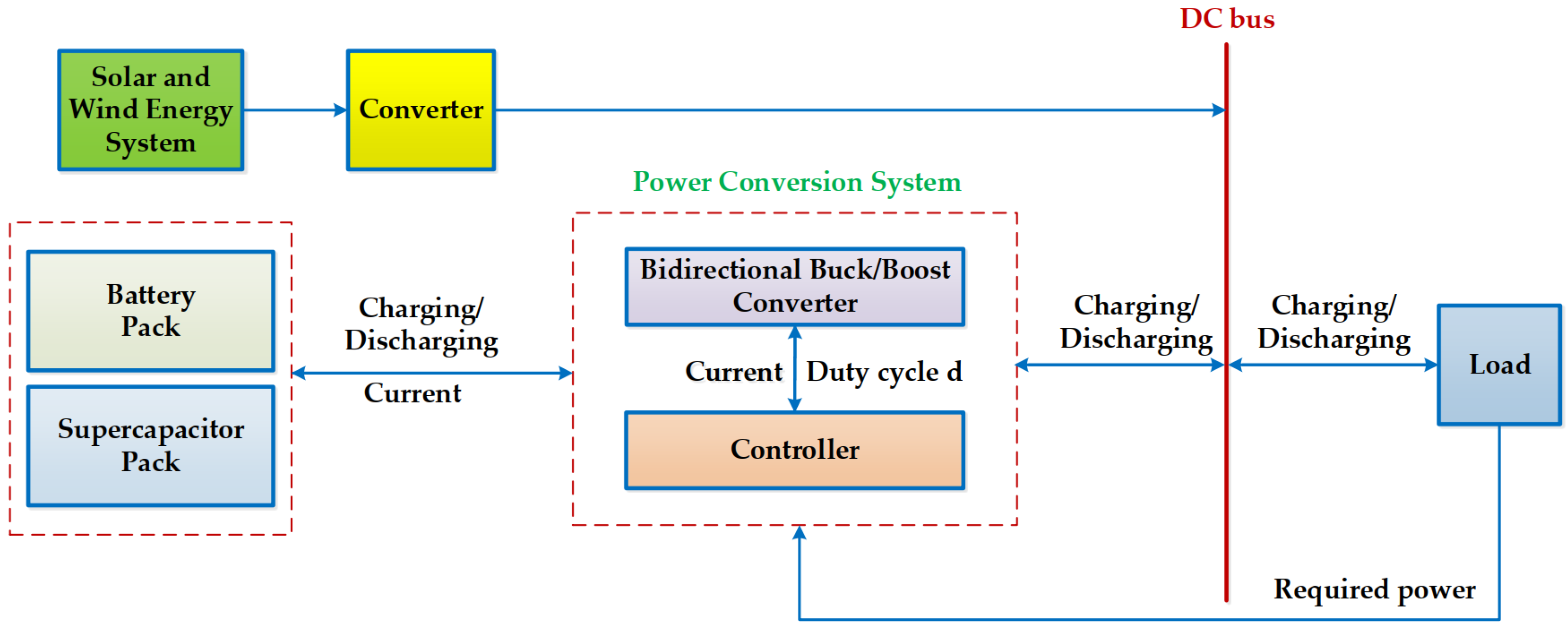
Global warming, climate change, the depletion of fossil fuel resources, and rising carbon emissions are all consequences of the growing demand for electric energy in recent years [1]. Eco-friendly energy sources are desperately needed to address these issues. As a result, electric vehicles and DC microgrids are now using renewable energy sources like wind and solar [2,3,4,5]. However, the primary reason for power fluctuations and instability is the erratic and sporadic nature of these renewable energy sources [6]. In order to address these problems, DC microgrids and electric vehicles employ energy storage systems made up of batteries (Bats) and supercapacitors (SCs) to balance the load’s power requirements [7,8,9]. However, Bats are unable to supply the required power of the load in transient response because of their high energy density and sluggish charging and discharging rates [10,11,12,13]. Because of their high power density and quick charging and discharging, SCs were developed to address Bats’ shortcomings [14,15,16,17,18,19]. However, SCs are unable to meet the high load requirement [20,21]. Thus, to solve all of the aforementioned problems in DC microgrids, a HESS comprising the high power and high energy density of SCs and Bats is needed, as illustrated in Figure 1. Controlling the HESS to meet the required power of the constantly fluctuating loads is extremely difficult because the HESS incorporates energy storage systems, such as slow dynamic in Bats and fast dynamic in SCs.

Figure 1.
Hybrid energy storage system in DC microgrids.
To tackle the above difficulty, PI- and PID-based control strategies for the HESS have been investigated in order to enhance the power performance of Bats and SCs [22,23,24]. The PI controller was created using frequency domain analysis [22], but stability is challenging because the method relies on small signal modeling. The conventional PID controller was created in [23,24] to be only locally stable, which lowers control quality when the load fluctuates constantly while the system is operating. The composite backstepping controllers in [25,26] and the model predictive controllers in [27,28] are two examples of the controller design studies for the HESS under load fluctuations that have been proposed to address problems [22,23,24]. However, it is challenging to guarantee control performance with these control methods because the HESS always operates with varying loads and parameter uncertainties. Multiple robust controllers, such as sliding mode controllers, have been developed to address these challenges [29,30]. However, in practice, SMCs also show discontinuity, and the chattering phenomenon in these SMCs is irreversible and challenging to minimize. Additionally, reinforcement learning control to estimate the HESS dynamics and iterative learning control to achieve smooth charging and discharging have been proposed [31,32,33]. Nevertheless, iterative computation leads to costly and sluggish transient response.
On the other hand, the stability and control quality of the HESS are significantly impacted by external disturbances, including measurement disturbances. To solve this problem, several extended state observer (ESO)-based control strategies have been proposed [34,35,36]. These include the cascade ESO in [34], the cascade–parallel ESO in [35], and the higher-order ESO in [36] to achieve disturbance rejection performance. However, these methods become more complex in terms of algorithmic implementation and computational time, and smooth transients cannot be guaranteed. Investigating DOB-based nonlinear control algorithms has also been suggested as a means of achieving robustness in control quality [37,38,39,40]. However, the HESS is a complicated system that consists of two energy storage systems with opposing features: Bats, which have a slow dynamic, and SCs, which have a fast dynamic. As a result, using a controller and a disturbance observer at the same time makes calculations more difficult. In practice, designing a disturbance observer can be particularly challenging due to the limited resources of microprocessors. Furthermore, the system parameters determine the disturbance observer’s design, and using erroneous model parameters will result in poorer estimation performance. Therefore, control methods without disturbance observers are required to attenuate the disturbances in the HESS.
To overcome the above-mentioned problems, this paper proposes the H∞ state feedback control with reference modulation without a disturbance observer in order to improve the power tracking performance in the HESS. The following is a summary of the main ideas of the suggested approach:
First, the two conventional bidirectional DC/DC converters’ control inputs for charging and discharging are recommended in order to meet the required load power.
Second, the reference modulation technique is developed to modulate the battery and supercapacitor’s required currents from the required load power. Without altering the system control signal, the reference modulation technique directly combines the feedforward channel and output feedback signal. We demonstrate that the suggested modulation relies on a current tracking error tuning module that is model-free, offering greater customization options for the intended disturbance attenuation performance. Hence, the benefit of the suggested reference modulation technique is that it can reduce the disturbance without the need for a disturbance observer. Furthermore, the feedforward channel improves transient response by increasing the loop gain over a desired performance.
Third, to enhance current tracking errors in the HESS for power tracking performance under the influence of measurement disturbances and parameter uncertainties without a disturbance observer, the H∞ state feedback control, which is based on the required currents of the battery and supercapacitor derived from the required load power modulated by the reference modulation technique, is proposed. The benefits of enhancing transient performance and attenuating disturbance without the need for a disturbance observer are noted in the above-mentioned second idea of the suggested approach.
Finally, the effectiveness of the proposed method is validated through study results with nominal parameters and parameter uncertainties under the influence of measurement disturbances.
This paper is composed of six sections. The hybrid energy storage system mathematical model is described in Section 2. The current tracking error dynamics are described in Section 3. The H∞ state feedback control based on the reference modulation technique is described in Section 4. The study results for the proposed control method are given in Section 5. Finally, Section 6 presents the conclusions.
2. Mathematical Model of a Hybrid Energy Storage System
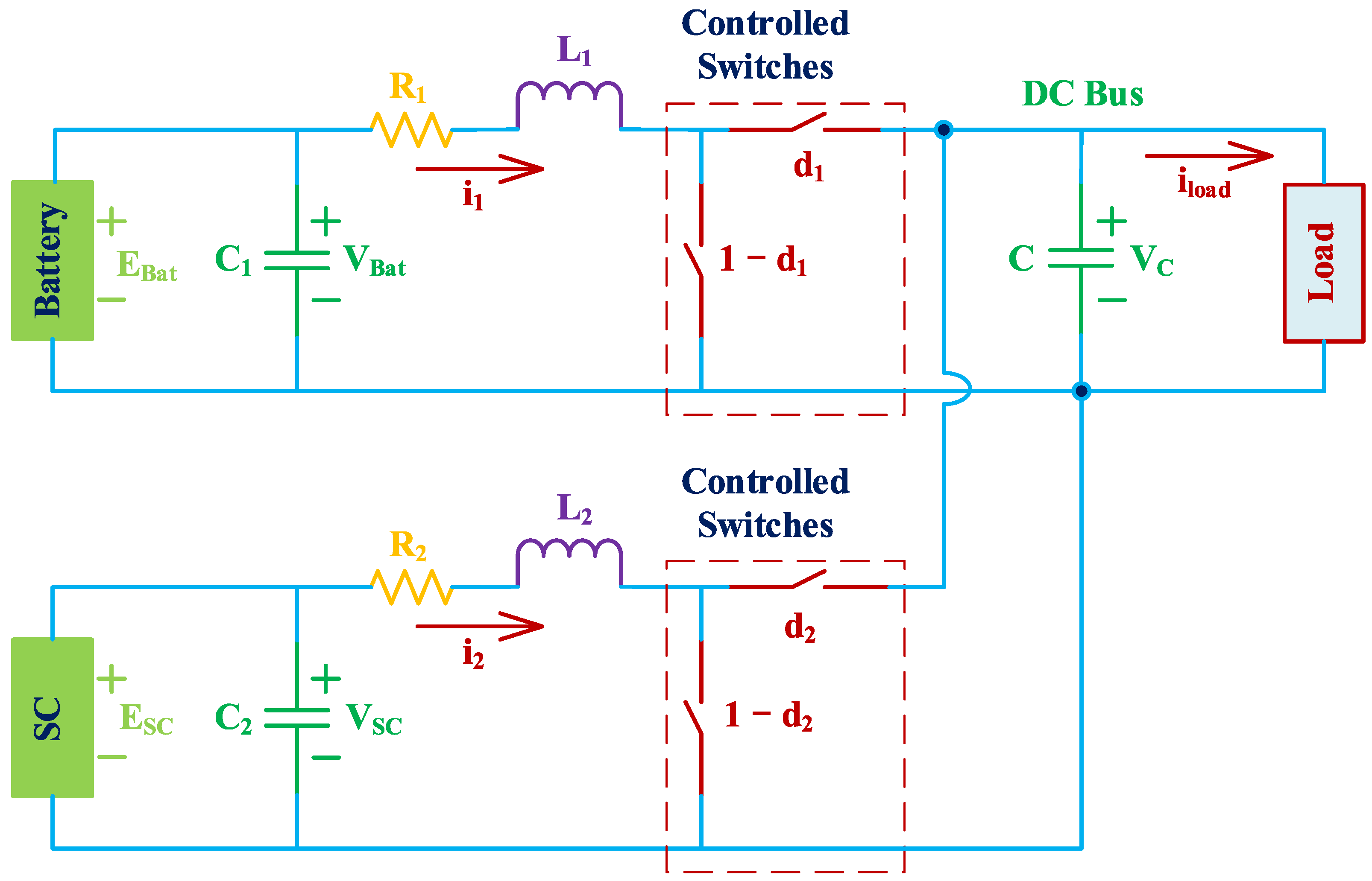
The HESS in DC microgrids consists of a load, two conventional bidirectional DC/DC converters, a battery pack, and a supercapacitor pack, as illustrated in Figure 2. The battery serves as the primary power source, and the output power is applied directly to the load while also preserving the load side’s balanced DC voltage. The SC recovers braking energy and gives the load its instantaneous peak power. Furthermore, the fully operational HESS minimizes battery damage from voltage and peak current fluctuations and enables the SC to function across a wider voltage range. The switches of the bidirectional DC/DC converters are controlled to satisfy both the energy demand strategy and the required load power. The mathematical model of the HESS during the switching phase in Figure 2 can be created using Kirchhoff’s law and the equivalent circuit model [12] is as follows:
where and are the battery side and supercapacitor side inductors; and are the battery side and supercapacitor side inductor currents; and are the series resistances of and ; and are the battery side and supercapacitor side filter capacitors; C is the DC bus capacitor; VBat is the battery terminal voltage; is the supercapacitor terminal voltage; is the relevant DC bus capacitor voltage; and and are the duty cycle of switches.
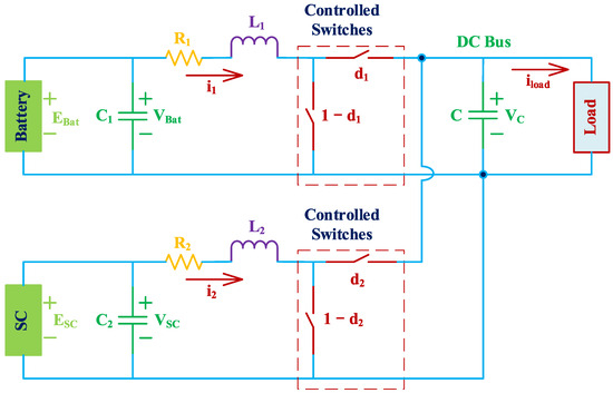
Figure 2.
Circuit model for the hybrid energy storage system.
Remark 1.
The load side is modeled as a current source instead of a resistive load because the load’s power requirements are always changing. A voltage source is used in place of the SC, internal characteristics are ignored, and the effects of uncertainty and disturbance are taken into consideration because the only goal of this study is to design the optimal current controller to satisfy the load power requirements for the HESS.
3. Current Tracking Error Dynamics
This section proposes the control inputs and in (1) of the switches of the bidirectional DC/DC converters in order to achieve the required load power, which varies continuously in practical applications, and stabilize the tracking current error dynamics.
Let us define the current tracking errors as follows:
where and represent the battery and supercapacitor’s required currents derived from the required load power. Based on (1) and (2), the following is a representation of the current tracking error dynamics:
For the load power requirements, we can now propose the control inputs and to stabilize the current tracking error dynamics in (3) as follows:
where and are state feedback control inputs that are designed in the next section using H∞ optimization with reference modulation.
By substituting (4) into (3), the current tracking error dynamics can be rewritten as follows:
Remark 2.
In this study, we only concentrate on designing the control inputs and to meet the required load power by stabilizing the dynamics of the current tracking errors. As a result, we assume that earlier research has balanced the DC bus voltage in the HESS [12,39]. However, we should also note that the DC bus voltage balancing in the HESS is guaranteed when the current tracking error dynamics (3) are stabilized, as the DC bus voltage control law is dependent on the battery and supercapacitor currents [12,39].
4. H∞ State Feedback Control Based on the Reference Modulation Technique
The reference modulation technique for the required currents of the battery and supercapacitor derived from the required load power and the optimal control design based on the reference modulation technique for and mentioned in Section 3 are proposed in this section. The H∞ norm is used to guarantee the current tracking error performance under the influence of parameter uncertainties and measurement disturbances.
4.1. Reference Modulation Technique
The reference modulation technique modulates the required currents of the battery and supercapacitor derived from the required load power without directly altering the system control signal. The reference modulation technique directly combines the feedforward channel and the actual output feedback signal as follows:
where and are direct feedforward channels, and and are modulation modules of the actual output feedback signal as follows:
where and are modulation gains, and these modulation gains are determined using the study’s methodology [41].
Remark 3.
The advantage of the suggested reference modulation technique for the required currents of the battery and supercapacitor derived from the required load power can attenuate the desired disturbance performance and improve the transient performance for reference tracking. Since the suggested modulation relies on a current tracking error tuning module in (6) that is model-free, it provides more customization options for the intended disturbance attenuation performance. Additionally, the feedforward channel raises the loop gain over a desired performance, which enhances transient response [41].
4.2. H∞ State Feedback Control Based on the Reference Modulation Technique
Enhancing current tracking error performance in the presence of measurement disturbances and parameter uncertainties is the goal of the H∞ state feedback control, which is based on the required currents of the battery and supercapacitor that were modulated in the previous subsection. The control inputs and in (4) are rewritten as follows:
Then, the current tracking error dynamics in (5) can be represented in the form of
where
where is the signal for the measurement disturbance, is the signal of the objective function, is the matrix of covariance, and and are the weighting matrices of the tracking errors and control inputs, respectively.
Under the influence of measurement disturbance and parameter uncertainties, the H∞ state feedback control, which is based on the required currents of the battery and supercapacitor that are modulated in (6), improves the current tracking error performance as follows:
where is the control gain.
In the optimal control design, we employed the H∞ control in the linear matrix inequality (LMI) technique [42] to ascertain the control gain in (9). The following is a definition of the performance specification in the H∞ norm:
The LMI condition is used to determine the bound on the H∞ norm by the H∞ state feedback control. The following statements are equivalent.
- There exists such that
- There exists such that
We then define a new variable , such that the control gain can be recovered by with the following LMI condition:
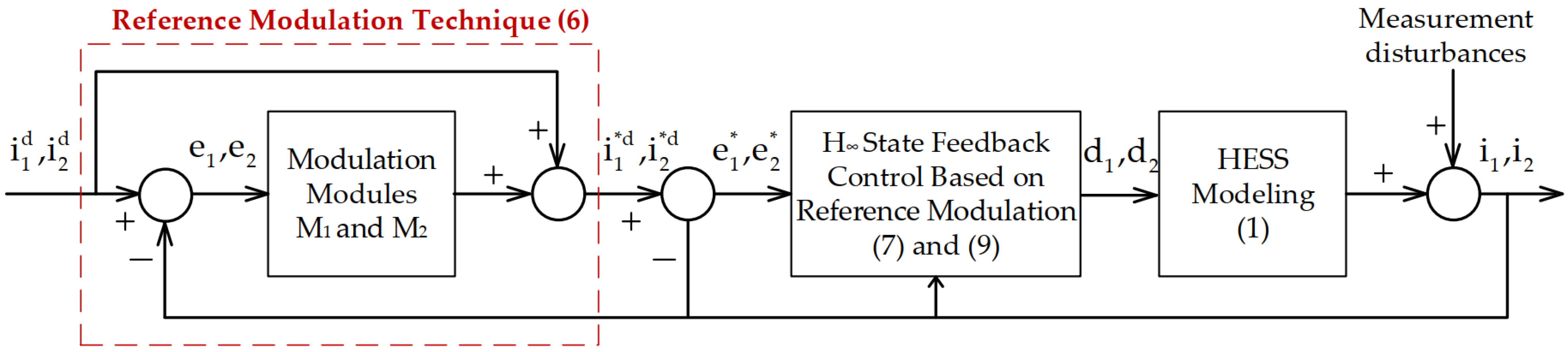
Figure 3 displays the proposed control method’s block diagram in the HESS.
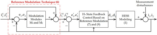
Figure 3.
Block diagram for the suggested control method in the HESS.
5. Study Results
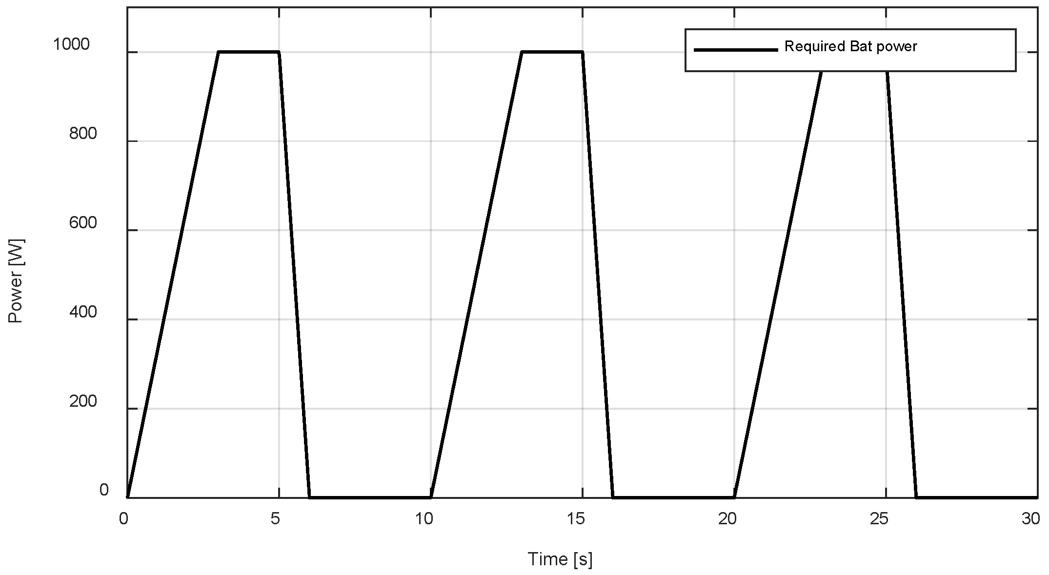
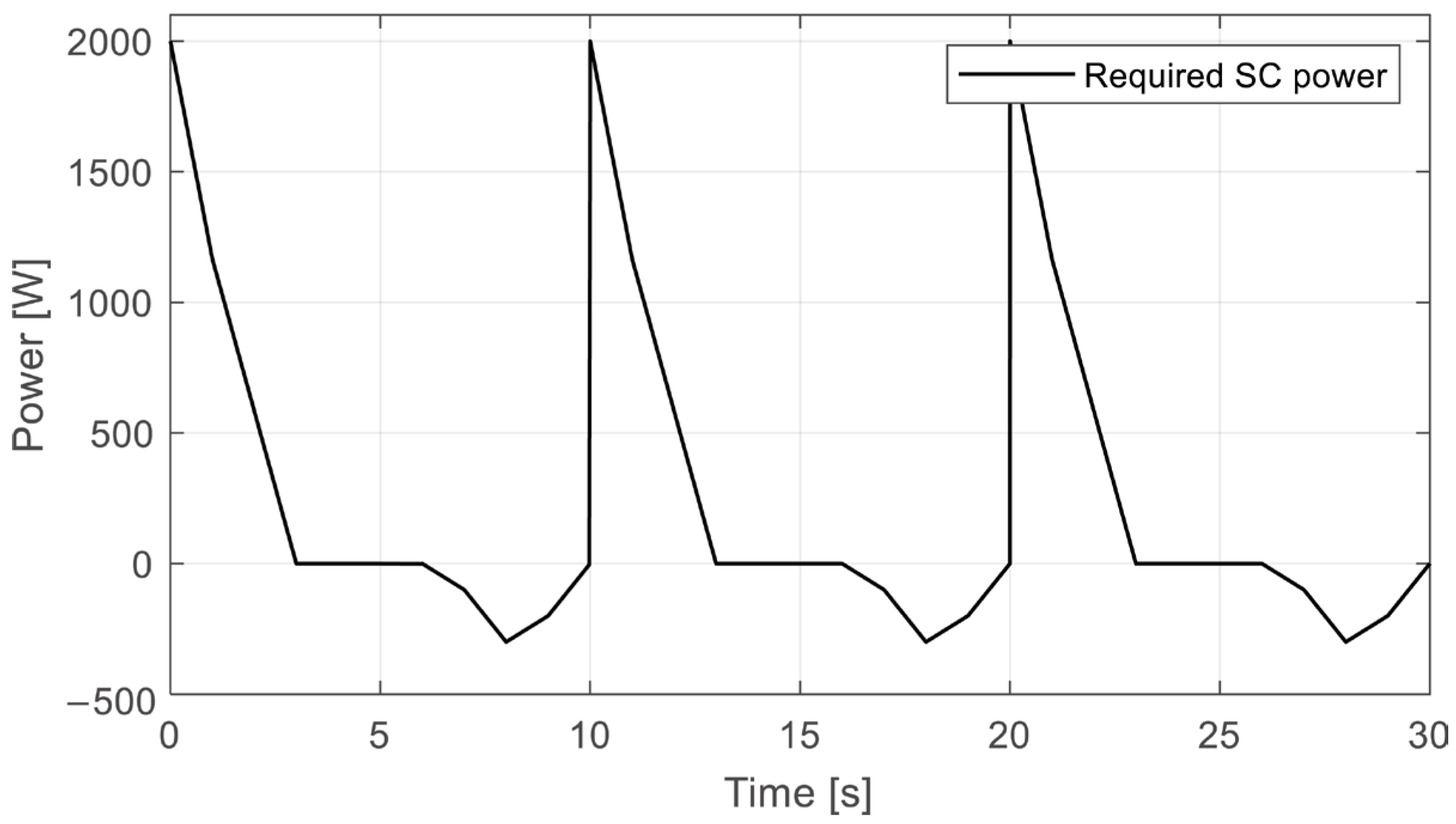
This section evaluates the efficacy of the proposed approach in the HESS by performing a study using the MATLAB(R2021b)/Simulink platform. Table 1 and Table 2 display the HESS parameters and the control and modulation gains. Figure 4, Figure 5 and Figure 6 illustrate the required power profiles for the load, battery, and supercapacitor:

Table 1.
HESS parameters [43].
Table 2.
Control and modulation gains of the proposed approach.
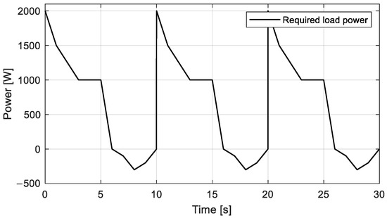
Figure 4.
Required load power profile.
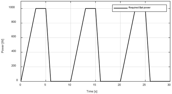
Figure 5.
Required battery power profile.
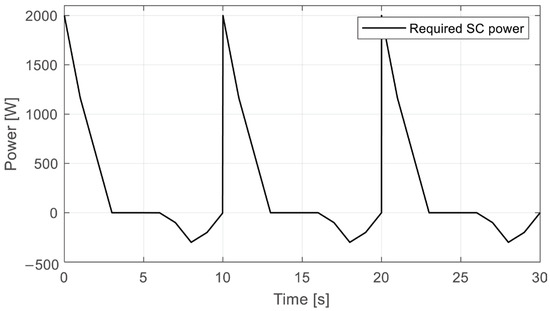
Figure 6.
Required supercapacitor power profile.
where
and the battery and supercapacitor’s required currents are determined as follows, respectively:
5.1. Study Results with Nominal Parameters
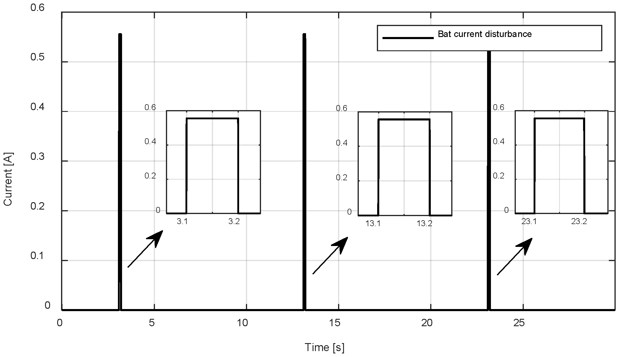
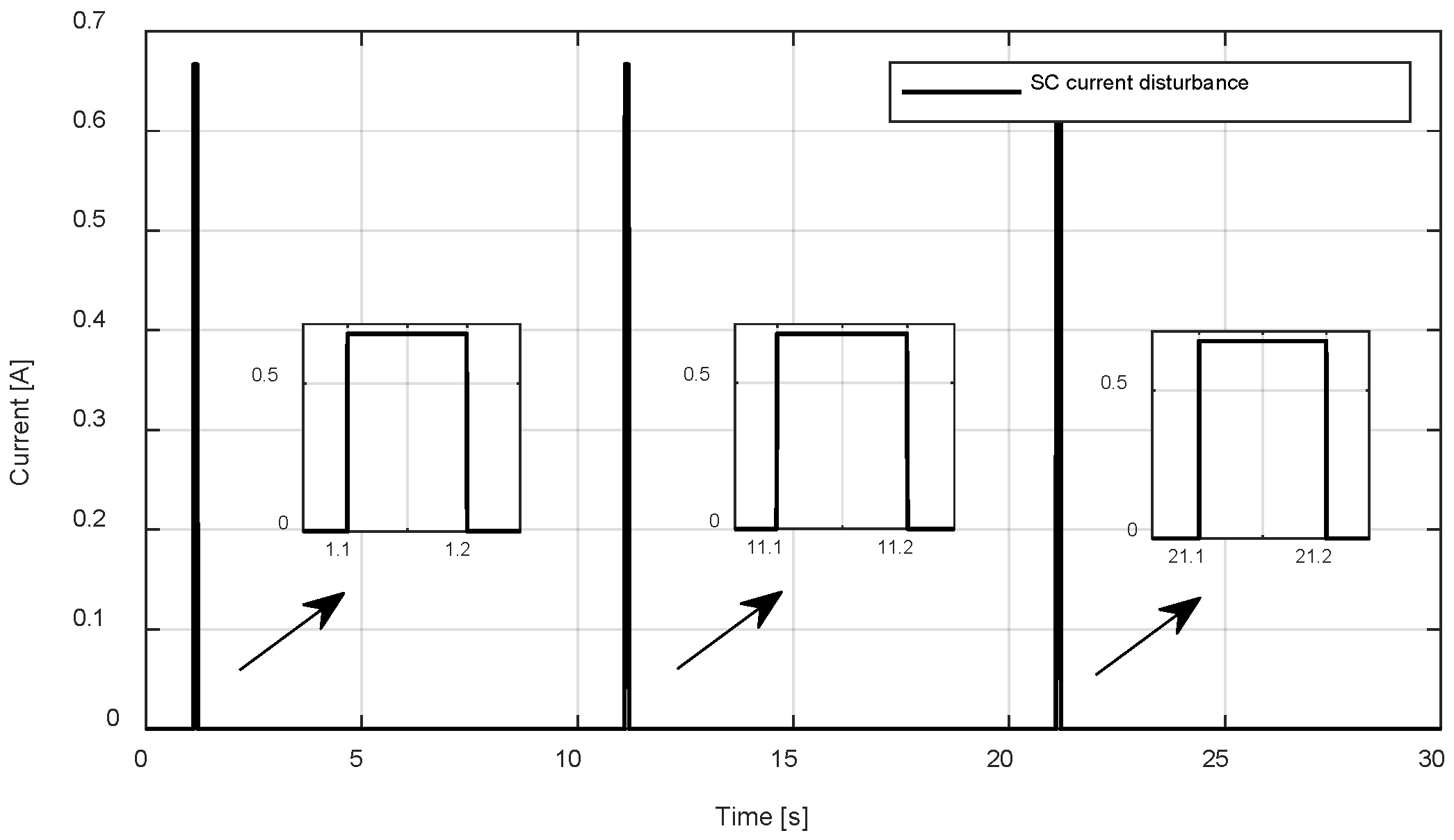
In this subsection, we perform simulations with measurement disturbances injected into the inductor currents of the battery and the supercapacitor in Figure 7 and Figure 8 to assess how well the proposed method improves the current tracking error performance to meet the required power of the variable load in practical applications for the HESS. The following is an analysis and comparison of the simulation results in three scenarios.

Figure 7.
Battery current disturbance.

Figure 8.
Supercapacitor current disturbance.
- Case 1: Classical PI control.
- Case 2: Traditional H∞ control.
- Case 3: Proposed method.
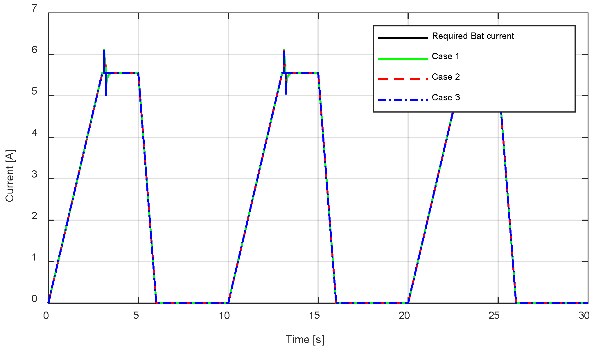
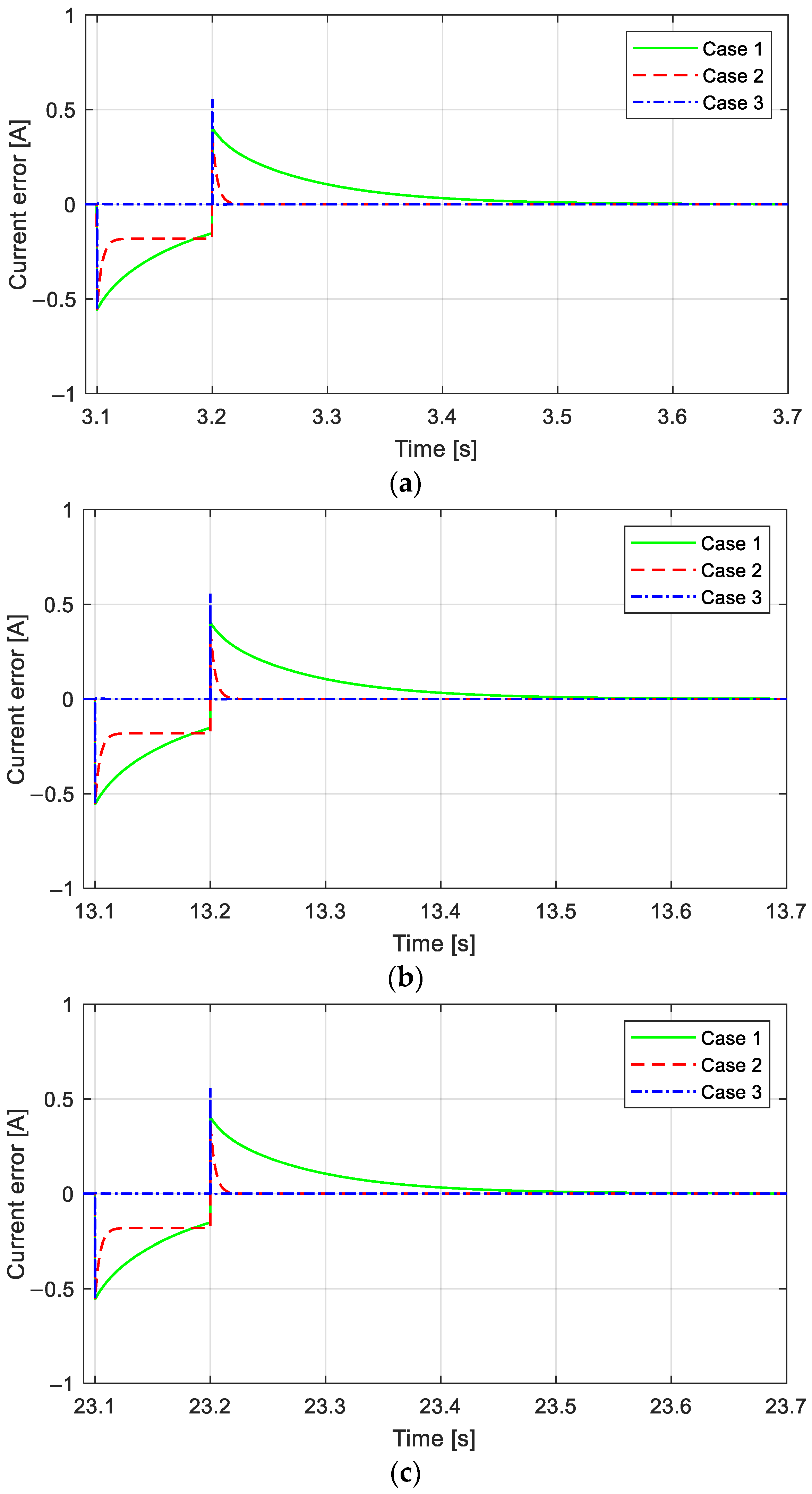
We start by examining the performance of the battery’s current tracking. As seen by the battery’s required load power profile in Figure 5, the battery only takes part in the discharge process, and between 3 s and 5 s, the discharge power progressively rises to the maximum requirement of 1000 W. After 5 s of each cycle, the battery will begin to take part in the discharge process, which will lower its power from 1000 W to 0. Figure 9 and Figure 10 show the battery’s current tracking performance. The effects of the measurement disturbance in Figure 7 can be lessened by the current tracking errors of cases 1, 2, and 3. However, as Figure 11a for cycle 1, Figure 11b for cycle 2, and Figure 11c for cycle 3 demonstrate, the current tracking errors of cases 1 and 2 never converge to zero during the time intervals from 3.1 s to 3.2 s, 13.1 s to 13.2 s, and 23.1 s to 23.2 s for three cycles. The current tracking errors of the battery discharge process in case 3 converge faster than those in cases 1 and 2 after being affected by the measurement disturbance because the H∞ norm in (10) always guarantees that the efficiency of H∞ control and the advantage of the suggested reference modulation technique of the required current, derived from the required Bat power, are applied. Furthermore, the large fixed controller gains of the classical PI control strategy used in case 1 make it evident that the transient response of case 1 is inferior to that of cases 2 and 3.
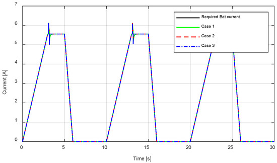
Figure 9.
Battery’s current tracking performance, .

Figure 10.
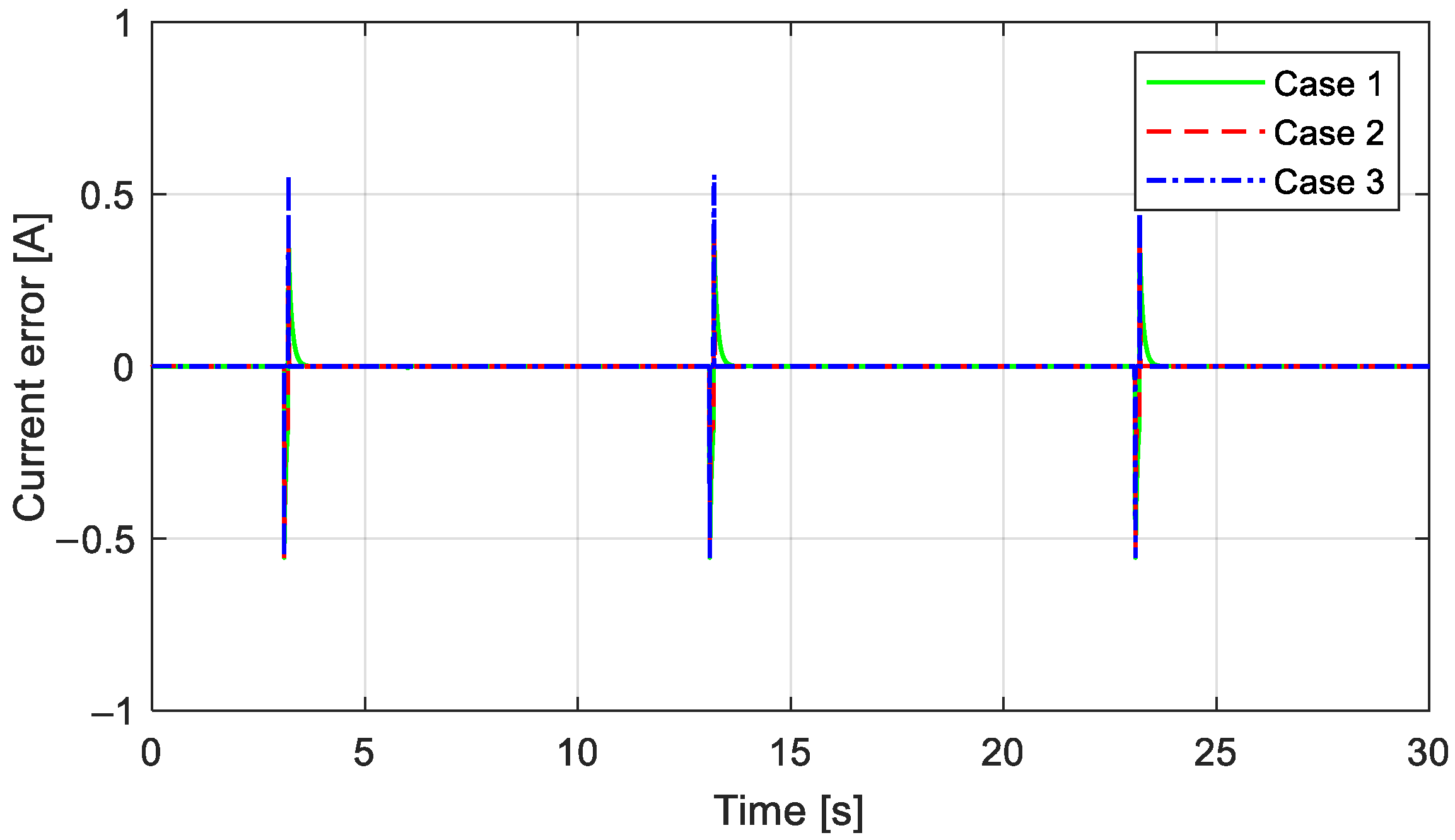
The battery’s current tracking error performance, .
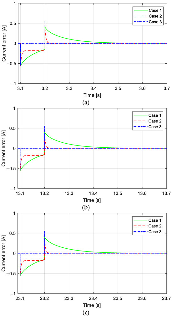
Figure 11.
An enlarged view of the battery’s current tracking error performance : (a) zoom in along the x-axis from 3.1 s to 3.7 s; (b) zoom in along the x-axis from 13.1 s to 13.7 s; and (c) zoom in along the x-axis from 23.1 s to 23.7 s.
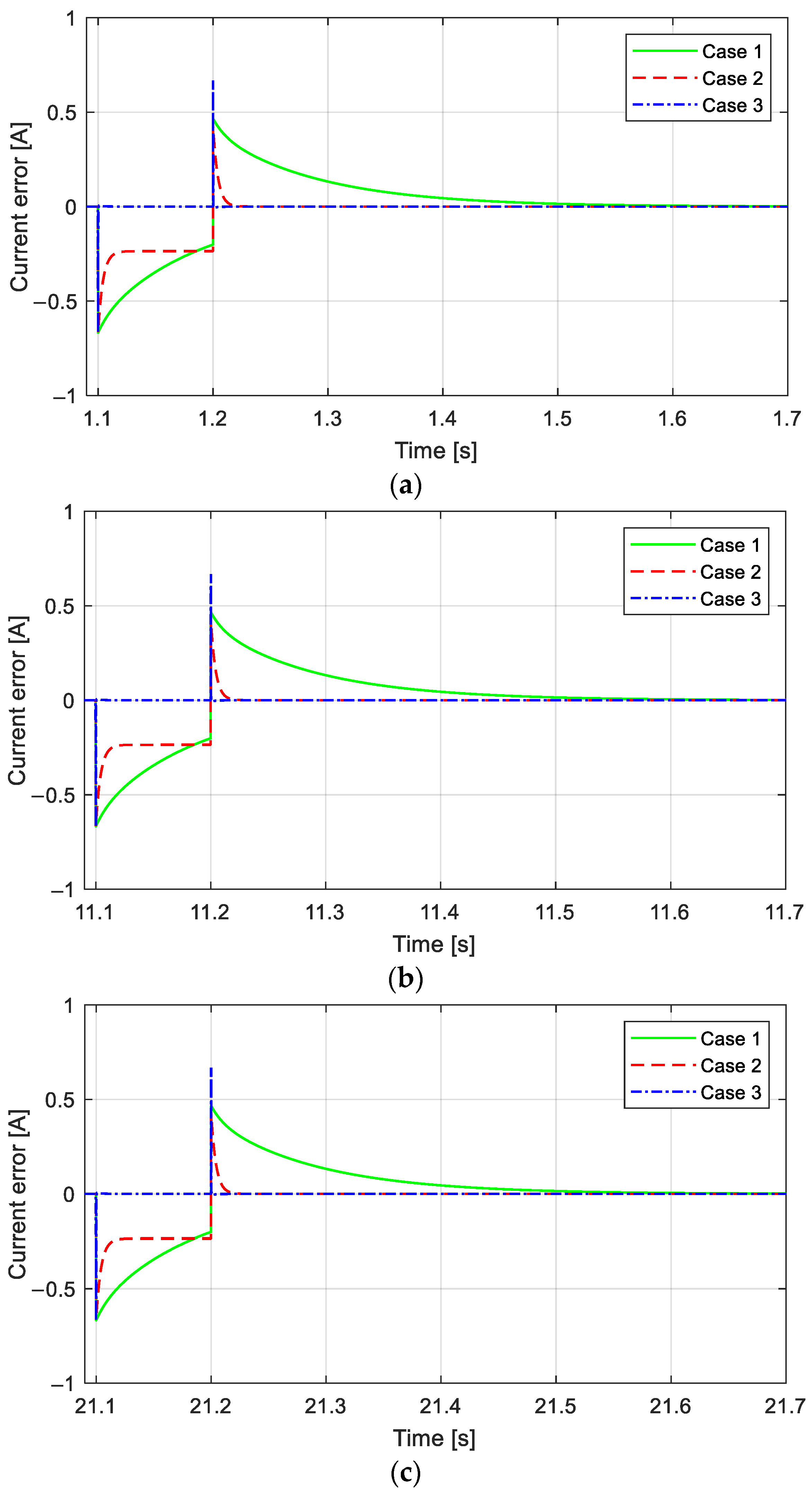
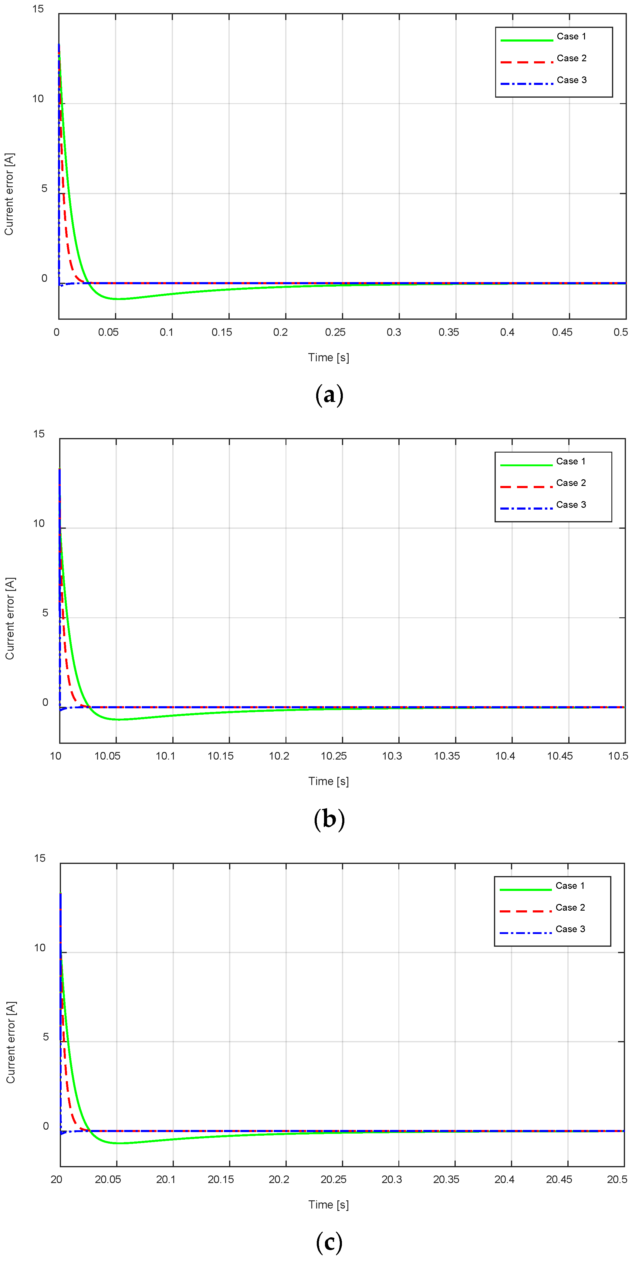
Second, we analyze the performance of the supercapacitor’s current tracking. The supercapacitor participates in both the charging and discharging processes, as evidenced by the required power profile in Figure 6. The load’s primary power source is the battery, which has a 1000 W limit. However, based on Figure 4’s continuously fluctuating power requirement, the required load power before 3 s is higher than 1000 W and begins at 2000 W per cycle. The supercapacitor energy supplies an instantaneous peak power to prevent the battery from being overloaded for 3 s and then the HESS reaches the required load power. This is made possible by the supercapacitor’s rapid discharge. Additionally, the supercapacitor’s fast charging capability allows it to recover braking energy from the required load power from 6 s to 10 s per cycle. This quick energy storage guarantees that the battery will be supported during transient responses and that the required load power will be satisfied. Consequently, the battery life of the HESS is extended. The supercapacitor’s current tracking performance is displayed in Figure 12 and Figure 13. In cases 1, 2, and 3, the current tracking errors during the discharge and charge of the supercapacitor can mitigate the effects of the measurement disturbance in Figure 8 on the time range of 1.1 s to 1.2 s, 11.1 s to 11.2 s, and 21.1 s to 21.2 s, respectively, for three cycles. However, under the influence of the measurement disturbance, the current tracking errors of cases 1 and 2 do not converge to zero, while those of case 3 do, as shown in Figure 14a for cycle 1, Figure 14b for cycle 2, and Figure 14c for cycle 3. Additionally, after being impacted by the measurement disturbance, the current tracking errors of the supercapacitor discharge process in case 3 converge faster than those in cases 1 and 2. Figure 15a–c demonstrate that case 3’s convergence time of the current tracking errors to zero at the start times of 0 s, 10 s, and 20 s of each cycle is quicker than cases 1 and 2. Similar to the battery, case 1’s transient response is subpar compared to cases 2 and 3. This is because of the classical PI controller’s previously stated drawbacks. Thus, we confirm that the supercapacitor’s current tracking performance in case 3 is better than in cases 1 and 2. Since the H∞ norm in (10) also guarantees the efficacy of H∞ control, the advantage of the suggested reference modulation technique of the required current derived from the required SC power is also applied.
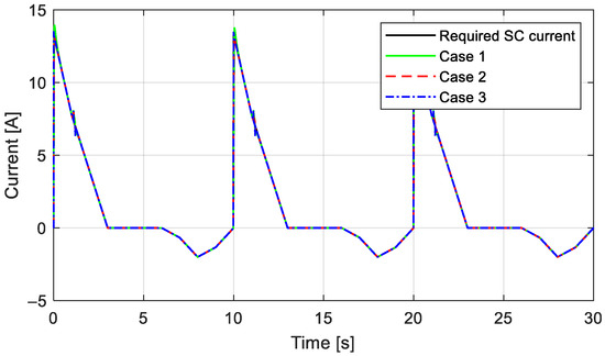
Figure 12.
Supercapacitor’s current tracking performance, .

Figure 13.
Supercapacitor’s current tracking error performance, .
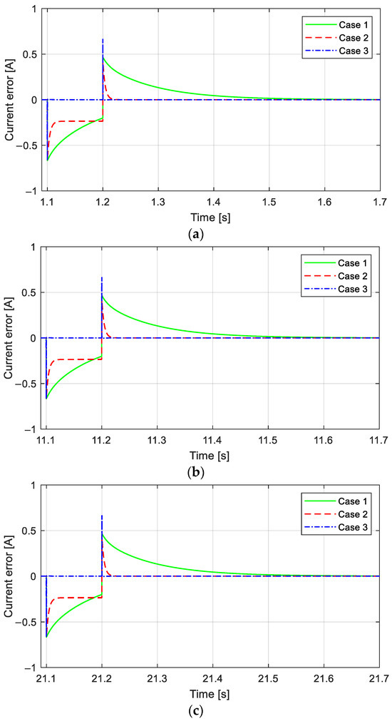
Figure 14.
An enlarged view of the supercapacitor’s current tracking error performance, : (a) zoom in along the x-axis from 1.1 s to 1.7 s; (b) zoom in along the x-axis from 11.1 s to 11.7 s; and (c) zoom in along the x-axis from 21.1 s to 21.7 s.
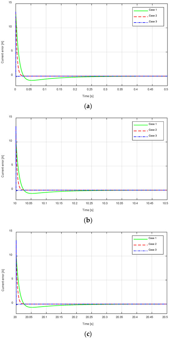
Figure 15.
An enlarged view of the supercapacitor’s current tracking error performance, : (a) zoom in along the x-axis at 0 s; (b) zoom in along the x-axis at 10 s; and (c) zoom in along the x-axis at 20 s.
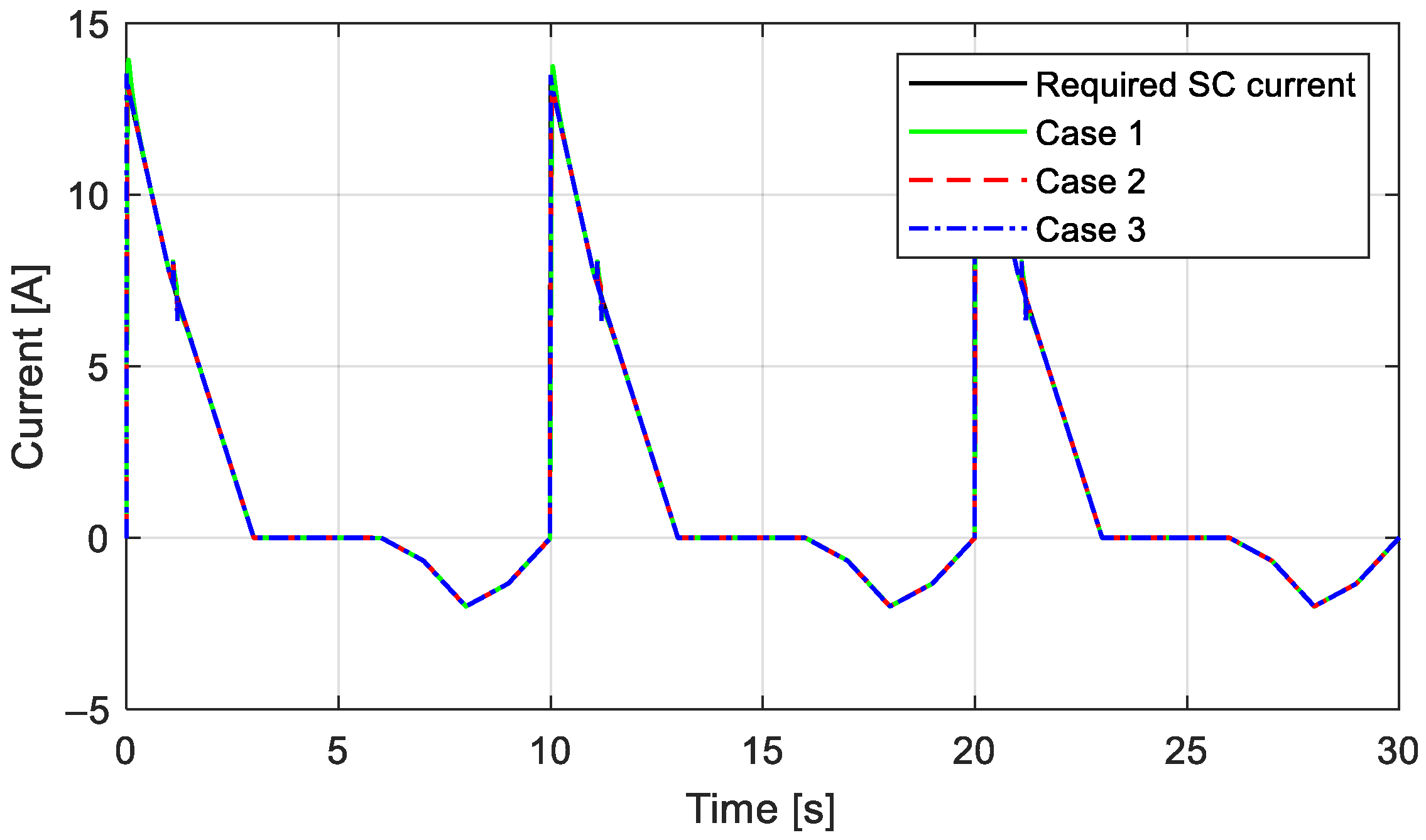
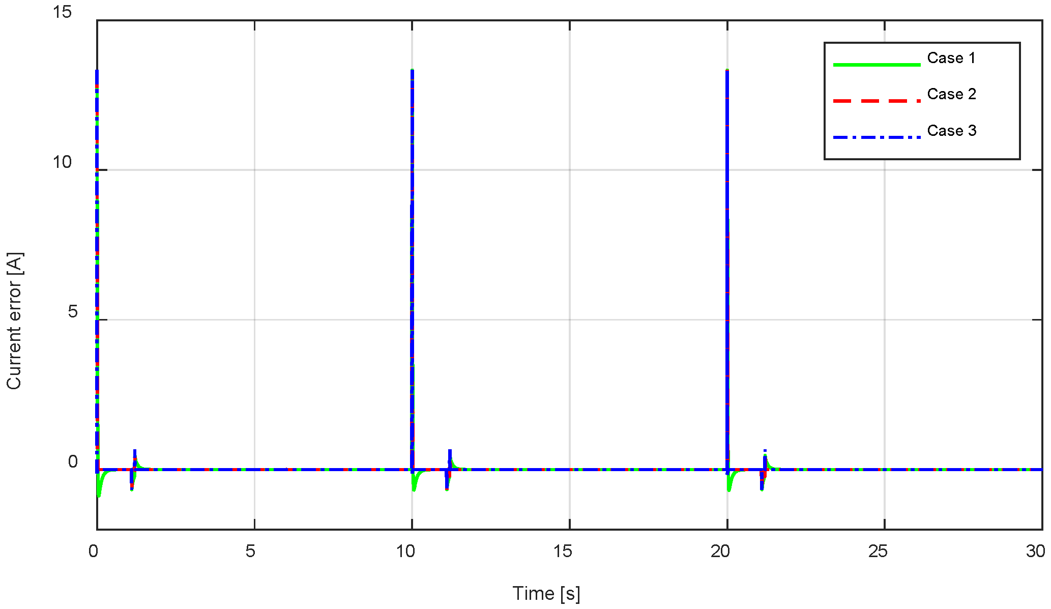
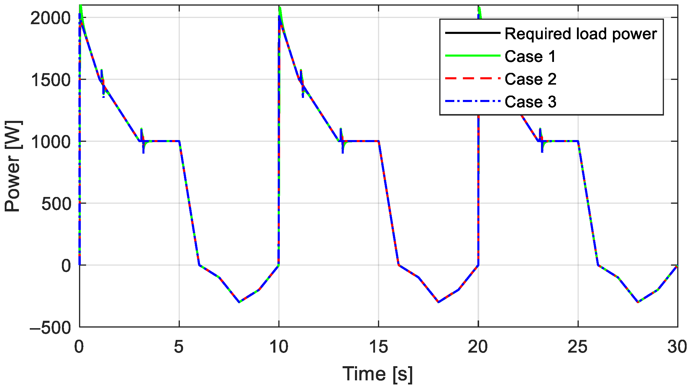
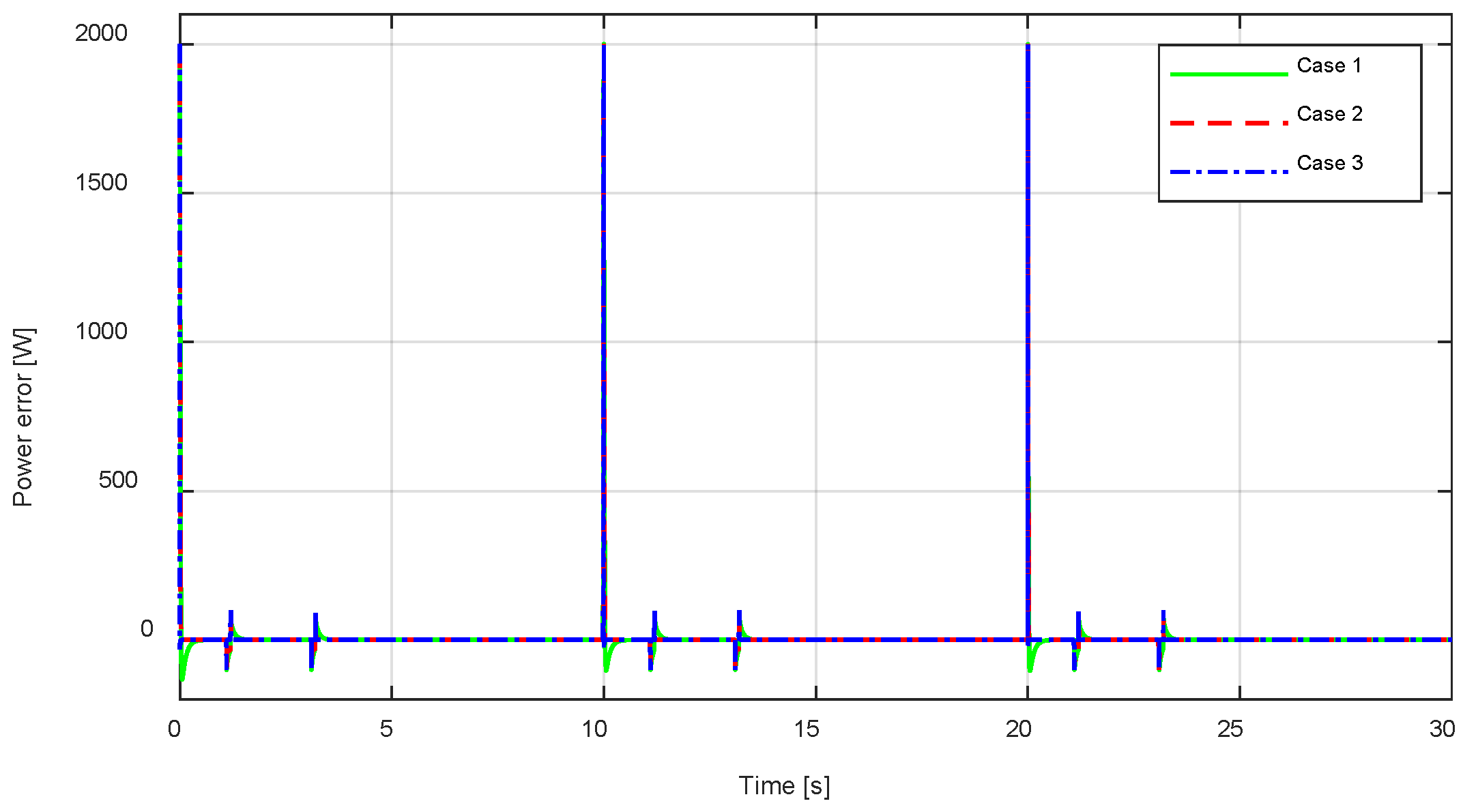
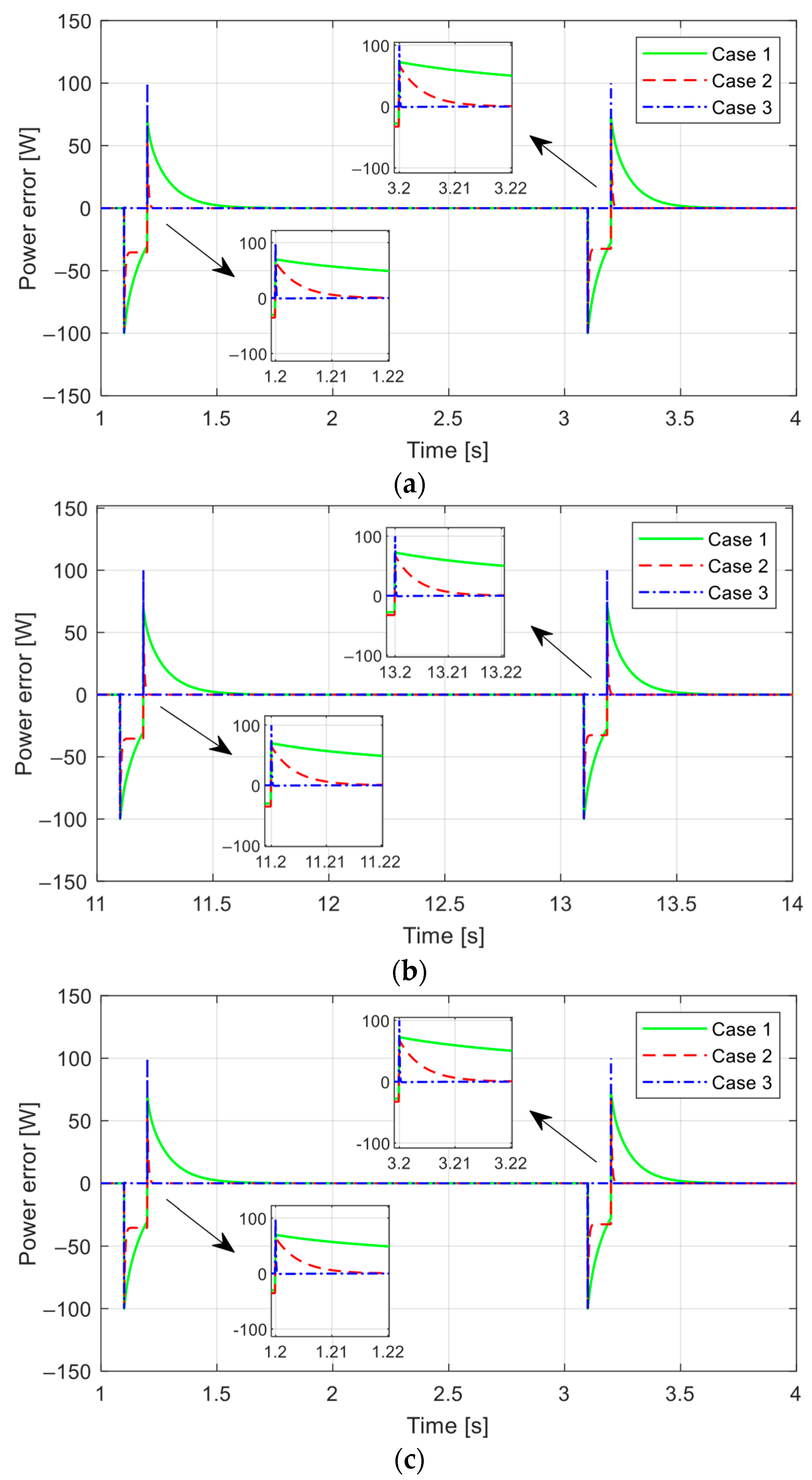
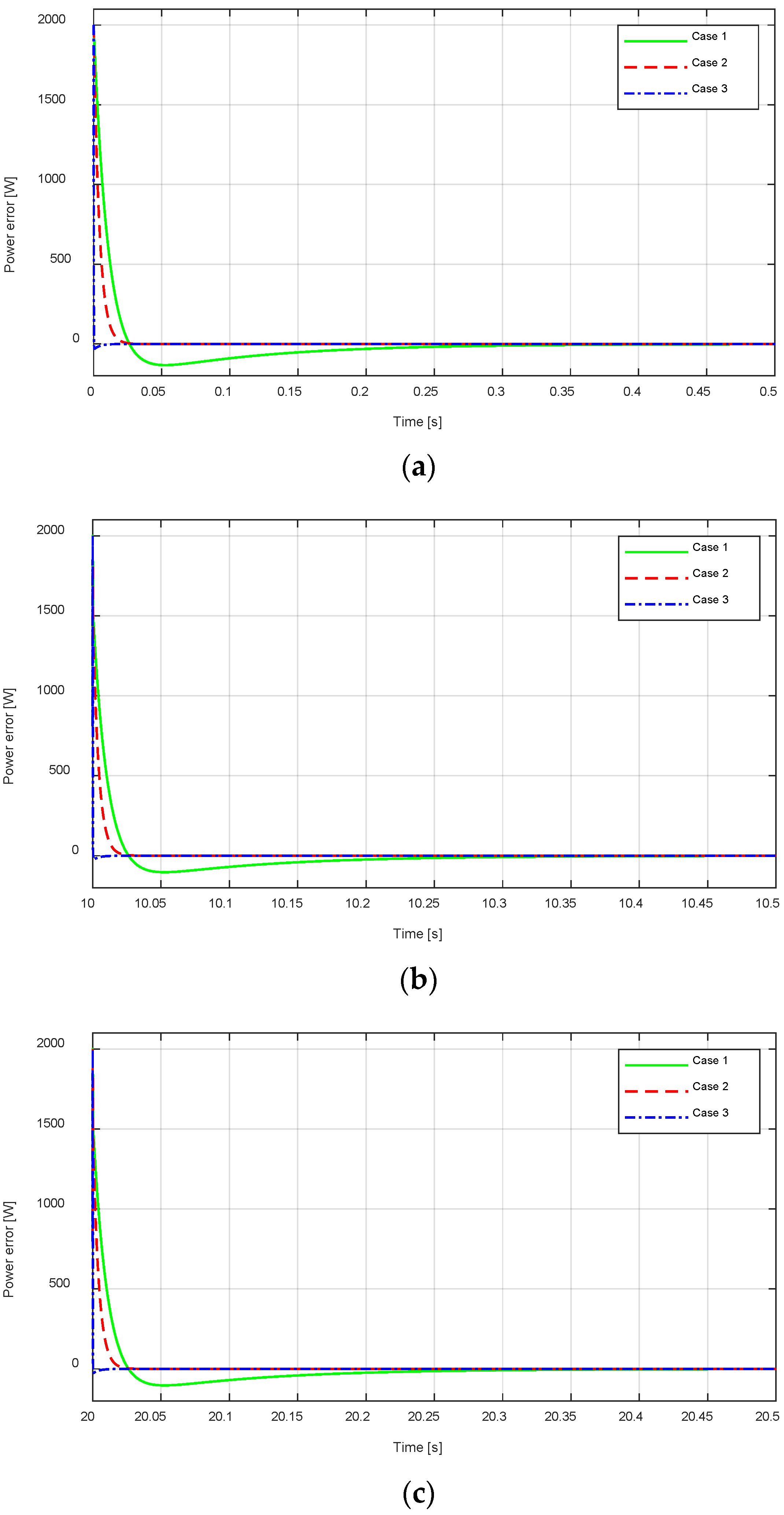
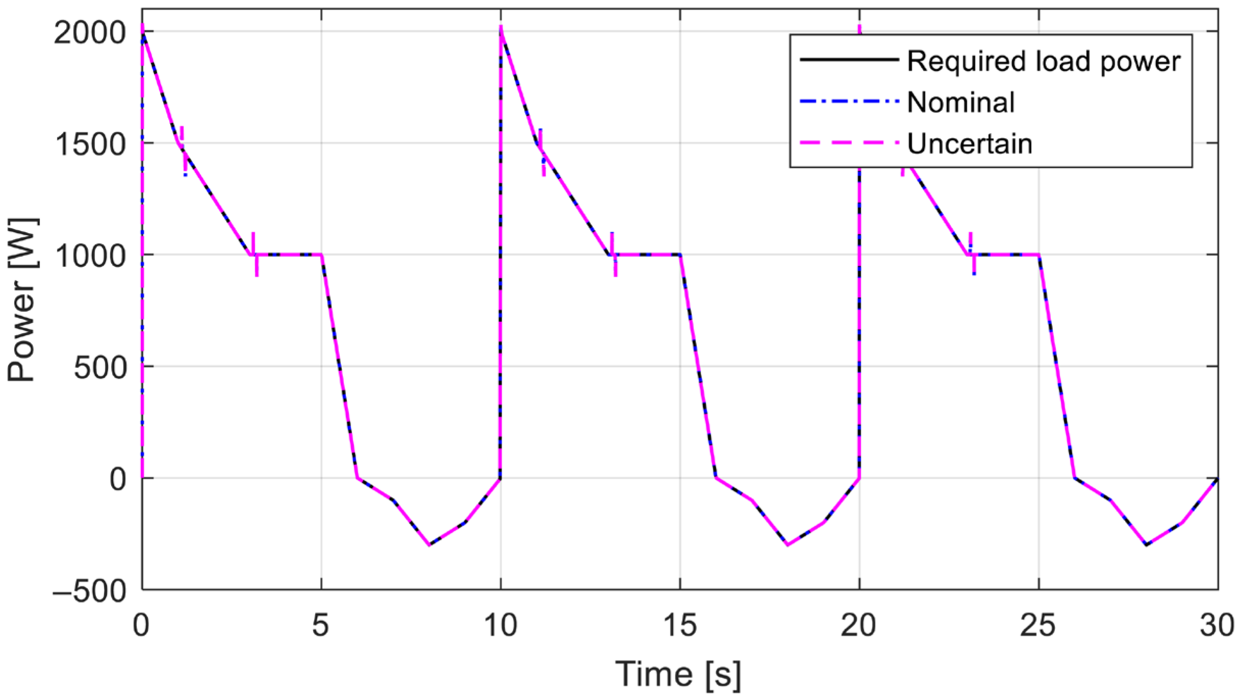
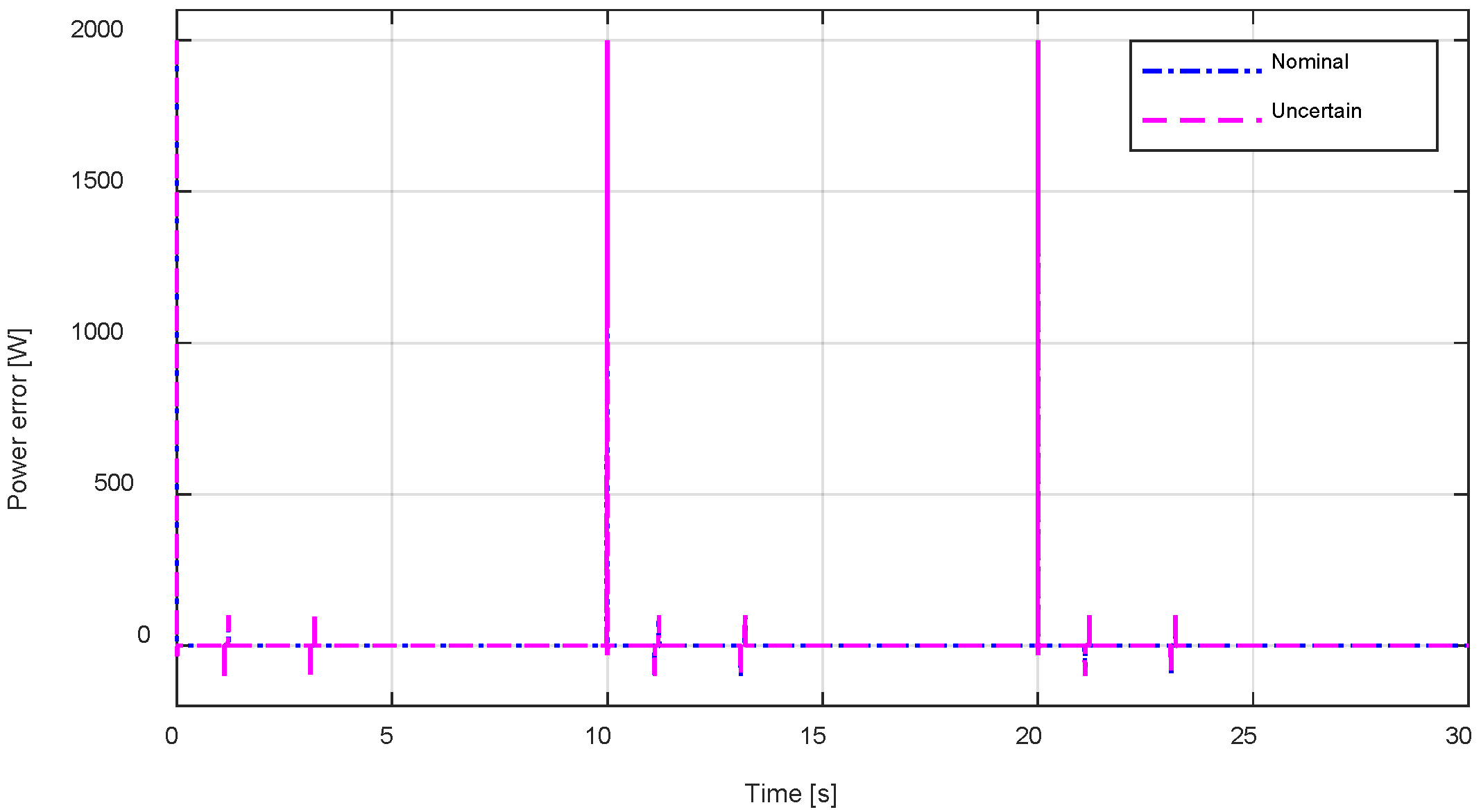
Finally, to assess how well the suggested approach controls the battery and supercapacitor current to provide the required load power, Figure 16 and Figure 17 display the power tracking performance results. Under the measurement disturbance shown in Figure 7 and Figure 8, the power tracking performance during the charge and discharge processes is enhanced in both scenarios 1, 2, and 3. However, as Figure 18a–c demonstrate, the power tracking errors of cases 1 and 2 under the influence of measurement disturbances on the battery and supercapacitor currents during all three cycles are unable to converge to zero, whereas the current tracking errors of case 3 rapidly do so. More specifically, in case 2, under the influence of measurement disturbances on battery and supercapacitor currents, the power tracking errors from 3.1 s to 3.2 s, from 13.1 s to 13.2 s, and from 23.1 s to 23.2 s are 32.5 W, and from 1.1 s to 1.2 s, from 11.1 s to 11.2 s, and from 21.1 s to 21.2 s are 35.3 W in all three cycles. Meanwhile, in case 1, the power tracking errors are greater than 32.5 W and 35.3 W during the disturbance-affected periods. Furthermore, at the beginning of each cycle and during times when measurement disturbances affect the battery and supercapacitor currents, the convergence time performance in case 3 is likewise faster than that in cases 1 and 2, as shown in Figure 18a–c and Figure 19a–c. The rate of change (ROC) for cases 1 and 3 is −98.57% after 0 s and −49.93% after 1.2 s and 3.2 s, according to Table 3 for cycle 1 for further analysis. In contrast, the ROC for cases 2 and 3 is −80% after 0 s and −8.95% after 1.2 s and 3.2 s. According to these ROC results, the proposed strategy in case 3 converges more quickly than the classical PI control method in case 1 and the H∞ control in case 2. Furthermore, it is evident that case 2’s rate of convergence is faster than case 1’s when comparing the ROCs of cases 1 and 2 with case 3. A similar methodology is used to analyze the rate of convergence in cycles 2 and 3. We verify that the proposed control approach has effectively improved power tracking performance to satisfy the required load power for the variable load while being affected by measurement disturbance in practical applications; this is because, in case 3, the effectiveness of H∞ control is always guaranteed by the H∞ norm in (10). In particular, the advantage of the proposed reference modulation technique in case 3 is that it attenuates disturbances without requiring the design of a disturbance observer. The traditional approach, which only employs traditional H∞ control in case 2 and classical PI control in case 1, differs significantly from case 3’s disturbance attenuation without a disturbance observer.
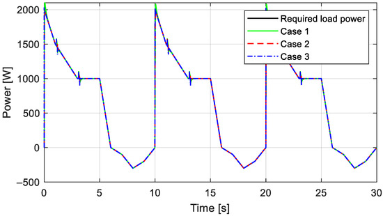
Figure 16.
Power tracking performance.
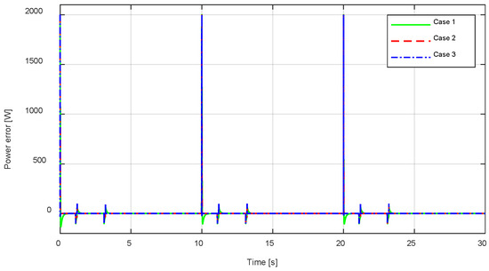
Figure 17.
Power tracking error performance.
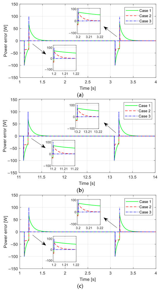
Figure 18.
An enlarged view of the power tracking error performance: (a) zoom in power tracking errors along the x-axis from 1 s to 4 s; (b) zoom in power tracking errors along the x-axis from 11 s to 14 s; and (c) zoom in power tracking errors along the x-axis from 21 s to 24 s.
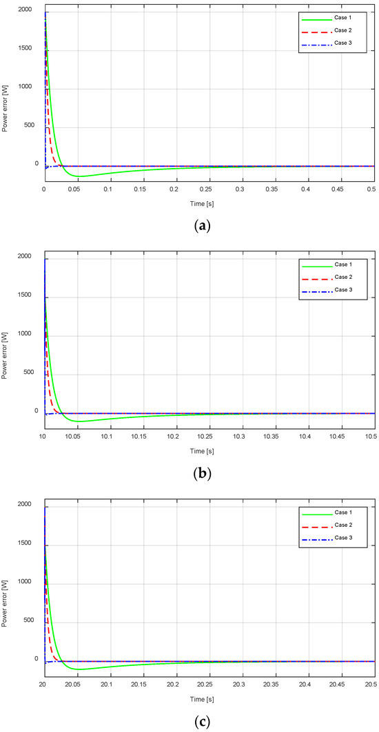
Figure 19.
An enlarged view of the power tracking error performance: (a) zoom in power tracking errors along the x-axis at 0 s; (b) zoom in power tracking errors along the x-axis at 10 s; and (c) zoom in power tracking errors along the x-axis at 20 s.
Table 3.
Performance comparison of convergence time in the three cases.
5.2. Study Results with Parameter Uncertainties
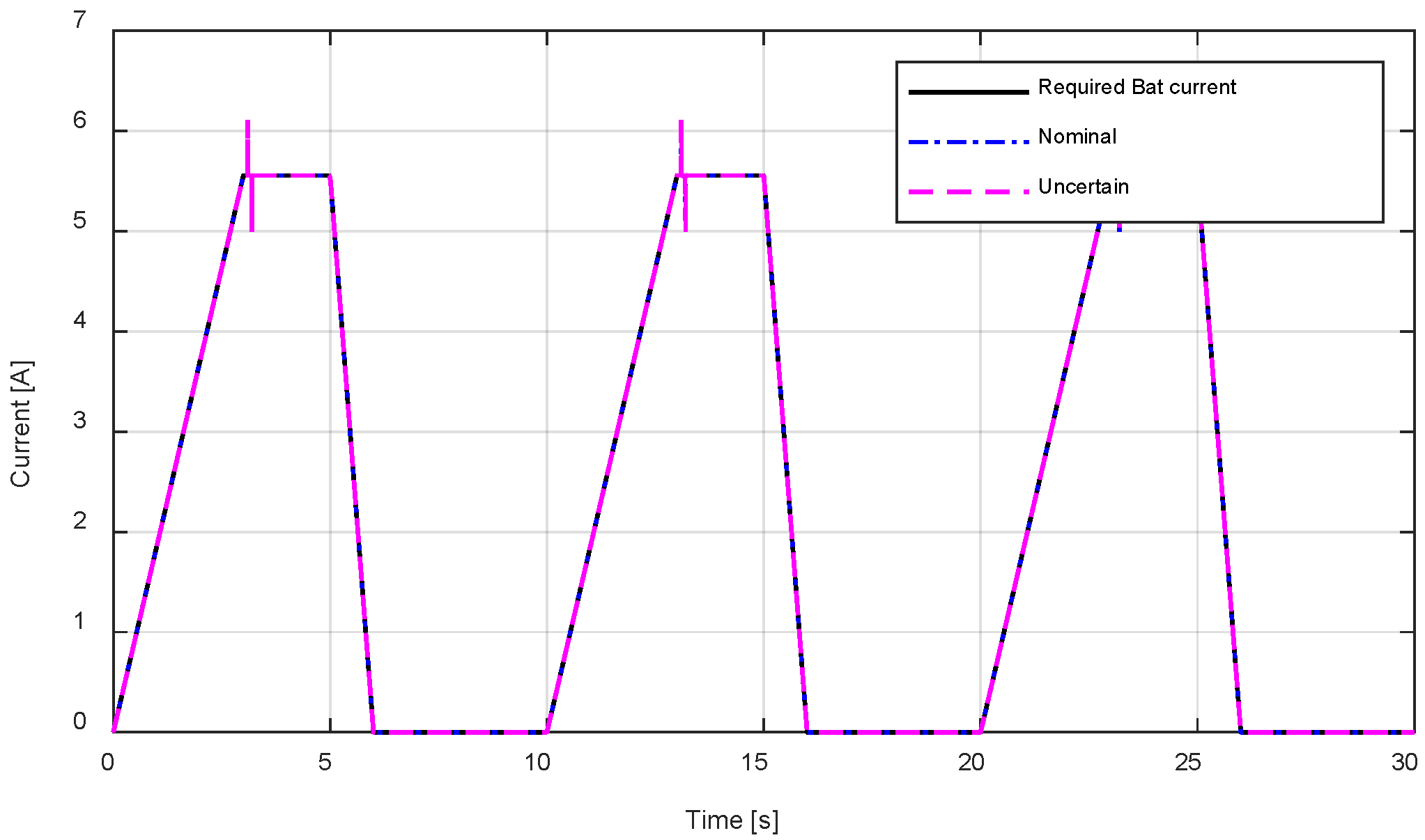
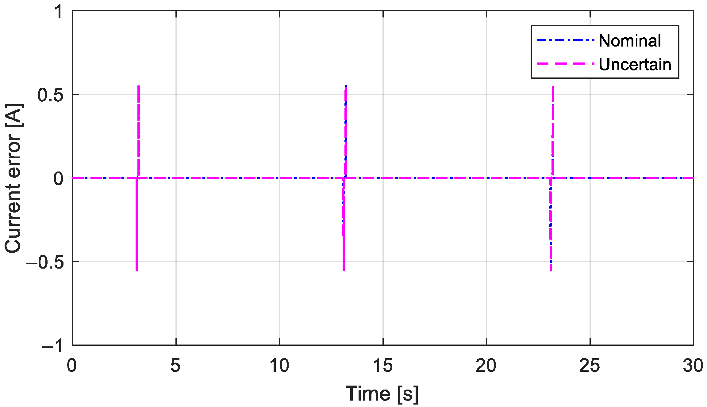
In this subsection, we present more research results to evaluate the robustness of the proposed method in the HESS to parameter uncertainties. The electrical structure and prolonged charging and discharging operations of the two conventional bidirectional DC/DC converters lead to manufacturing tolerance, which implies that their parameters are not fixed and will change in response to uncertainties in the system parameters. Depending on the temperature and frequency of the environment, the electrical parameters can be more easily changed to function like the series resistances (R1 and R2) and inductors (L1 and L2). In order to assess the robustness of the suggested method, we compared the study results with uncertainties in the series resistances and inductors up to 20% of the nominal parameters as follows:
Figure 20 and Figure 21 display the current tracking performance of the battery and the supercapacitor results compared to the nominal parameter results. In case 2 of the suggested method, we observe that the amplitude and setting time of the current tracking errors in Figure 22 and Figure 23 are similar to the nominal parameter results. Thus, in the case of parameter uncertainties, the current tracking performance of the battery and the supercapacitor in Figure 20 and Figure 22 is guaranteed. This results in the outcomes illustrated in Figure 24 and Figure 25, which indicate that the power tracking performance of the HESS is also guaranteed and satisfies the power requirement of the continuously varying load in practical applications. Because the H∞ norm in (10) always guarantees the H∞ control based on the recommended reference modulation technique for required currents, we conclude that the suggested method is robust against measurement disturbances and parameter uncertainties.
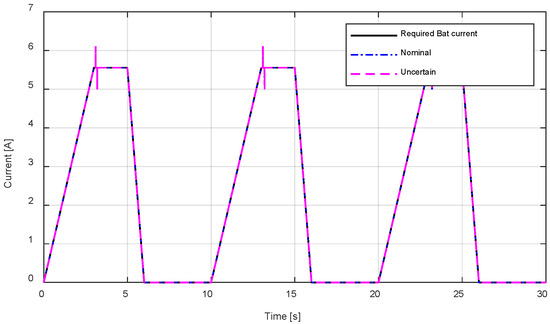
Figure 20.
Battery’s current tracking performance, , with parameter uncertainties.
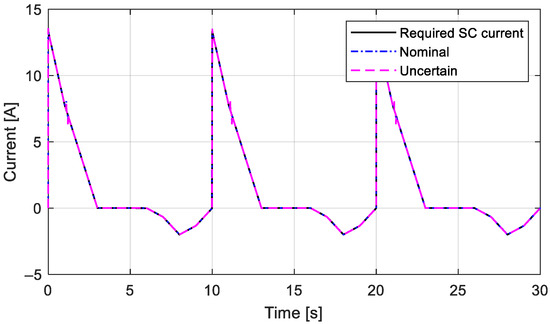
Figure 21.
Supercapacitor’s current tracking performance, , with parameter uncertainties.
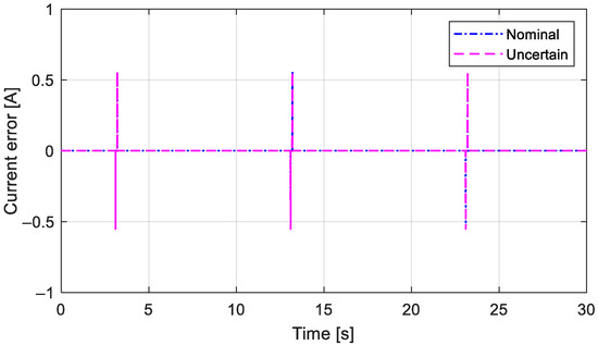
Figure 22.
Battery’s current tracking error performance, , with parameter uncertainties.
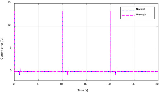
Figure 23.
Supercapacitor’s current tracking error performance, , with parameter uncertainties.
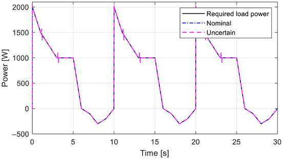
Figure 24.
Power tracking performance with parameter uncertainties.
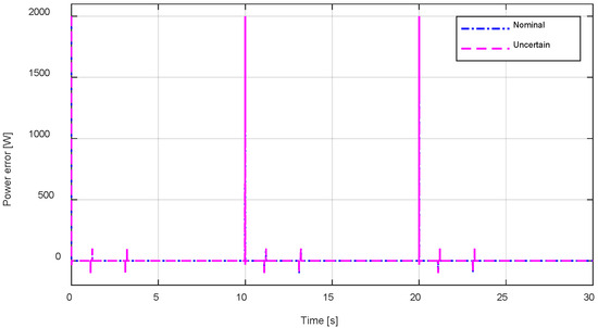
Figure 25.
Power tracking error performance with parameter uncertainties.
6. Conclusions
This paper proposes a control strategy to enhance the power tracking performance of the HESS in DC microgrids, incorporating reference modulation and H∞ state feedback control. In order to modulate the required currents of the battery and supercapacitor derived from the required load power, the reference modulation technique combined the feedforward channel with the actual output feedback signal without directly altering the system control signal. The proposed H∞ state feedback control, which was based on the required currents modulated by the reference modulation technique, was designed to improve the current tracking errors in the battery and supercapacitor. The HESS power tracking error and battery and supercapacitor current tracking errors converged to zero in the steady state region more quickly with the suggested control strategy. The proposed control strategy showed a similar transient response to the results of the nominal parameters when parameter uncertainties were considered. The study results validated the enhancement of power tracking performance and robustness of the HESS in DC microgrids under the influence of measurement disturbances and parameter uncertainties without a disturbance observer.
The design of a reference modulation optimization technique utilizing the mixed H2/H∞ with multiple control objectives in power tracking performance in the HESS is one potential avenue for future research. Examining the calculation burden in hard real-time systems for the experimental environment is another potential area of future research.
Author Contributions
Conceptualization, K.H.S. and Y.S.S.; methodology, K.H.S. and Y.S.S.; software, K.H.S. and Y.S.S.; validation, K.H.S., Y.S.S. and Y.L.; formal analysis, K.H.S., Y.S.S. and Y.L.; investigation, K.H.S. and Y.S.S.; resources, K.H.S. and Y.L.; writing—original draft preparation, K.H.S. and Y.S.S.; writing—review and editing, K.H.S. and Y.L.; supervision, Y.L.; project administration, Y.L.; funding acquisition, Y.L. All authors have read and agreed to the published version of the manuscript.
Funding
This work was supported in part by an Institute of Information & Communications Technology Planning & Evaluation (IITP) grant funded by the Korean government (MSIT) (No. RS-2021-II212068, Artificial Intelligence Innovation Hub); in and partly by the Technology Innovation Program (No. 20014121, Development of integrated Minimal Risk Maneuver technology for fallback system during autonomous Driving) funded By the Ministry of Trade, Industry & Energy (MOTIE, Republic of Korea), and partly in part by the MSIT (Ministry of Science and ICT), Korea, under the ITRC (Information Technology Research Center) support program (IITP-2024-RS-2024-00437756) supervised by the IITP (Institute for Information & Communications Technology Planning & Evaluation).
Data Availability Statement
The original contributions presented in this study are included in the article. Further inquiries can be directed to the corresponding author(s).
Conflicts of Interest
The authors declare that they have no conflicts of interest.
References
- Sebestyén, V. Renewable and sustainable energy reviews: Environmental impact networks of renewable energy power plants. Renew. Sustain. Energy Rev. 2021, 151, 111626. [Google Scholar] [CrossRef]
- Patel, S.; Ghosh, A.; Ray, P.K. Efficient power management and control of DC microgrid with supercapacitor-battery storage systems. J. Energy Storage 2023, 73, 109082. [Google Scholar] [CrossRef]
- AlKawak, O.A.; Kumar, J.R.R.; Daniel, S.S.; Reddy, C.V.K. Hybrid method based energy management of electric vehicles using battery-super capacitor energy storage. J. Energy Storage 2024, 77, 109835. [Google Scholar] [CrossRef]
- Raut, K.; Shendge, A.; Chaudhari, J.; Lamba, R.; Alshammari, N.F. Modeling and simulation of photovoltaic powered battery-supercapacitor hybrid energy storage system for electric vehicles. J. Energy Storage 2024, 82, 110324. [Google Scholar] [CrossRef]
- Rekioua, D. Energy storage systems for photovoltaic and wind systems: A review. Energies 2023, 16, 3893. [Google Scholar] [CrossRef]
- Lin, X.; Zamora, R. Controls of hybrid energy storage systems in microgrids: Critical review, case study and future trends. J. Energy Storage 2022, 47, 103884. [Google Scholar] [CrossRef]
- Abdelghany, M.B.; Al-Durra, A.; Gao, F. A coordinated optimal operation of a grid-connected wind-solar microgrid incorporating hybrid energy storage management systems. IEEE Trans. Sustain. Energy 2024, 15, 39–51. [Google Scholar] [CrossRef]
- Jithin, S.; Rajeev, T. Novel adaptive power management strategy for hybrid AC/DC microgrids with hybrid energy storage systems. J. Power Electron. 2022, 22, 2056–2068. [Google Scholar] [CrossRef]
- Naderi, E.; Bibek, K.C.; Ansari, M.; Asrari, A. Experimental validation of a hybrid storage framework to cope with fluctuating power of hybrid renewable energy-based systems. IEEE Trans. Energy Convers. 2021, 36, 1991–2001. [Google Scholar] [CrossRef]
- Prudhvi Kumar, G.R.; Sattianadan, D.; Vijayakumar, K. A survey on power management strategies of hybrid energy systems in microgrid. Int. J. Electr. Comput. Eng. 2020, 10, 1667–1673. [Google Scholar] [CrossRef]
- Gangatharan, S.; Rengasamy, M.; Elavarasan, R.M.; Das, N.; Hossain, E.; Sundaram, V.M. A novel battery supported energy management system for the effective handling of feeble power in hybrid microgrid environment. IEEE Access 2020, 8, 217391–217415. [Google Scholar] [CrossRef]
- Ghorashi, K.A.S.A.; Habibi, S.I.; Khalili, T.; Bidram, A. A model predictive control strategy for performance improvement of hybrid energy storage systems in DC microgrids. IEEE Access 2022, 10, 25400–25421. [Google Scholar] [CrossRef]
- Surulivel, N.; Sunny, A.C.; Dev, D.; Samanta, A.K.; Debnath, D. A novel four-port converter with all bi-directional ports having common ground for photo-voltaic hybrid energy storage DC system. IEEE Trans. Circuits Syst. II Express Briefs 2024, 71, 4571–4575. [Google Scholar] [CrossRef]
- Naseri, F.; Karimi, S.; Farjah, E.; Schaltz, E. Supercapacitor management system: A comprehensive review of modeling, estimation, balancing, and protection techniques. Renew. Sustain. Energy Rev. 2021, 155, 111913. [Google Scholar] [CrossRef]
- Olabi, A.G.; Abbas, Q.; Al Makky, A.; Abdelkareem, M.A. Supercapacitors as next generation energy storage devices: Properties and applications. Energy 2022, 248, 123617. [Google Scholar] [CrossRef]
- Zhang, J.; Gu, M.; Chen, X. Supercapacitors for renewable energy applications: A review. Micro Nano Eng. 2023, 21, 100229. [Google Scholar] [CrossRef]
- Chen, X.; Li, M.; Chen, Z. Meta rule-based energy management strategy for battery/supercapacitor hybrid electric vehicles. Energy 2023, 285, 129365. [Google Scholar] [CrossRef]
- Kouchachvili, L.; Yaïci, W.; Entchev, E. Hybrid battery/supercapacitor energy storage system for the electric vehicles. J. Power Sources 2018, 374, 237–248. [Google Scholar] [CrossRef]
- Rekioua, D.; Kakouche, K.; Babqi, A.; Mokrani, Z.; Oubelaid, A.; Rekioua, T.; Azil, A.; Ali, E.; Alaboudy, A.H.K.; Abdelwahab, S.A.M. Optimized power management approach for photovoltaic systems with hybrid battery-supercapacitor storage. Sustainability 2023, 15, 14066. [Google Scholar] [CrossRef]
- Rajput, A.K.; Lather, J.S. Energy management of a DC microgrid with hybrid energy storage system using PI and ANN based hybrid controller. Int. J. Ambient. Energy 2023, 44, 703–718. [Google Scholar] [CrossRef]
- Singh, P.; Lather, J.S. Power management and control of a grid-independent DC microgrid with hybrid energy storage system. Sustain. Energy Technol. Assess. 2020, 43, 100924. [Google Scholar] [CrossRef]
- Kotra, S.; Mishra, M.K. Design and stability analysis of DC microgrid with hybrid energy storage system. IEEE Trans. Sustain. Energy 2019, 10, 1603–1612. [Google Scholar] [CrossRef]
- Salari, O.; Zaad, K.H.; Bakhshai, A.; Jain, P. Reconfigurable hybrid energy storage system for an electric vehicle DC-AC inverter. IEEE Trans. Power Electron. 2020, 35, 12846–12860. [Google Scholar] [CrossRef]
- Ye, K.; Li, P. A new adaptive PSO-PID control strategy of hybrid energy storage system for electric vehicles. Adv. Mech. Eng. 2020, 12, 168781402095857. [Google Scholar] [CrossRef]
- Alipour, M.; Zarei, J.; Razavi-Far, R.; Saif, M.; Mijatovic, N.; Dragičević, T. Observer-based backstepping sliding mode control design for microgrids feeding a constant power load. IEEE Trans. Ind. Electron. 2023, 70, 465–473. [Google Scholar] [CrossRef]
- Sarrafan, N.; Zarei, J.; Horiyat, N.; Razavi-Far, R.; Saif, M.; Mijatovic, N. A novel fast fixed-time backstepping control of DC microgrids feeding constant power loads. IEEE Trans. Ind. Electron. 2023, 70, 5917–5926. [Google Scholar] [CrossRef]
- Xu, Q.; Yan, Y.; Zhang, C.; Dragicevic, T.; Blaabjerg, F. An offset-free composite model predictive control strategy for DC/DC buck converter feeding constant power loads. IEEE Trans. Power Electron. 2020, 35, 5331–5342. [Google Scholar] [CrossRef]
- Zhang, M.; Xu, Q.; Zhang, C.; Nordstrom, L.; Blaabjerg, F. Decentralized coordination and stabilization of hybrid energy storage systems in DC microgrids. IEEE Trans. Smart Grid 2022, 13, 1751–1761. [Google Scholar] [CrossRef]
- Lin, P.; Zhang, C.; Zhang, X.; Iu, H.H.C.; Yang, Y.; Blaabjerg, F. Finite-time large signal stabilization for high power DC microgrids with exact offsetting of destabilizing effects. IEEE Trans. Ind. Electron. 2021, 68, 4014–4026. [Google Scholar] [CrossRef]
- Jiang, W.; Zhang, X.; Guo, F.; Chen, J.; Wang, P.; Koh, L.H. Large-signal stability of interleave boost converter system with constant power load using sliding-mode control. IEEE Trans. Ind. Electron. 2020, 67, 9450–9459. [Google Scholar] [CrossRef]
- Duan, J.; Yi, Z.; Shi, D.; Lin, C.; Lu, X.; Wang, Z. Reinforcement-learning-based optimal control of hybrid energy storage systems in hybrid AC–DC microgrids. IEEE Trans. Ind. Inform. 2019, 15, 5355–5364. [Google Scholar] [CrossRef]
- Liu, X.K.; Jiang, H.; Wang, Y.W.; He, H. A distributed iterative learning framework for DC microgrids: Current sharing and voltage regulation. IEEE Trans. Emerg. Top. Comput. Intell. 2020, 4, 119–129. [Google Scholar] [CrossRef]
- Zhang, X.; Wang, B.; Gamage, D.; Ukil, A. Model predictive and iterative learning control based hybrid control method for hybrid energy storage system. IEEE Trans. Sustain. Energy 2021, 12, 2146–2158. [Google Scholar] [CrossRef]
- Zhuo, S.; Gaillard, A.; Xu, L.; Bai, H.; Paire, D.; Gao, F. Enhanced robust control of a DC-DC converter for fuel cell application based on high-order extended state observer. IEEE Trans. Transp. Electrif. 2020, 6, 278–287. [Google Scholar] [CrossRef]
- Babayomi, O.; Zhang, Z. Model-free predictive control of power converters with multifrequency extended state observers. IEEE Trans. Ind. Electron. 2023, 70, 11379–11389. [Google Scholar] [CrossRef]
- Babayomi, O.; Zhang, Z. Model-free predictive control of power converters with cascade-parallel extended state observers. IEEE Trans. Ind. Electron. 2023, 70, 10215–10226. [Google Scholar] [CrossRef]
- Wu, Y.; Wang, L.; Zhang, J.; Li, F. Path following control of autonomous ground vehicle based on nonsingular terminal sliding mode and active disturbance rejection control. IEEE Trans. Veh. Technol. 2019, 68, 6379–6390. [Google Scholar] [CrossRef]
- Nguyen, A.T.; Basit, B.A.; Choi, H.H.; Jung, J.W. Disturbance attenuation for surface-mounted PMSM drives using nonlinear disturbance observer-based sliding mode control. IEEE Access 2020, 8, 86345–86356. [Google Scholar] [CrossRef]
- Zhang, X.; Wang, Y.; Yuan, X.; Shen, Y.; Lu, Z. Adaptive dynamic surface control with disturbance observers for battery/supercapacitor-based hybrid energy sources in electric vehicles. IEEE Trans. Transp. Electrif. 2023, 9, 5165–5181. [Google Scholar] [CrossRef]
- Li, Z.; Wang, B.; Xian, L.; Zhang, M.; Xu, Q. Decentralized active disturbance rejection control for hybrid energy storage system in DC microgrid. IEEE Trans. Ind. Electron. 2024, 71, 14232–14243. [Google Scholar] [CrossRef]
- Lee, Y.; Sun, L.; Moon, J.; Chung, C.C.; Tomizuka, M. Reference modulation for performance enhancement of motion control systems with nonlinear parameter variations. IEEE/ASME Trans. Mechatron. 2019, 24, 2040–2051. [Google Scholar] [CrossRef]
- Su, K.H.; Park, K.; Son, Y.S.; Lee, Y. Performance optimization with LPV synthesis for disturbance attenuation in planar motors. Mathematics 2024, 12, 3293. [Google Scholar] [CrossRef]
- Lu, Z.; Zhang, X. Composite non-linear control of hybrid energy-storage system in electric vehicle. Energies 2022, 15, 1567. [Google Scholar] [CrossRef]


Disclaimer/Publisher’s Note: The statements, opinions and data contained in all publications are solely those of the individual author(s) and contributor(s) and not of MDPI and/or the editor(s). MDPI and/or the editor(s) disclaim responsibility for any injury to people or property resulting from any ideas, methods, instructions or products referred to in the content. |
© 2025 by the authors. Licensee MDPI, Basel, Switzerland. This article is an open access article distributed under the terms and conditions of the Creative Commons Attribution (CC BY) license (https://creativecommons.org/licenses/by/4.0/).