Abstract
This paper presents an optimal model for the design of elliptical isolated footings subjected to biaxial bending under the minimum cost criterion, assuming that the footing rests on elastic soils and that the soil pressure distribution is linear. The methodology is developed in two parts. The first is used to obtain the minimum area, and the second is used to determine the minimum cost. Some authors show the equations for circular and elliptical footings for moments, bending shear, and punching shear. However, they do not present the minimum cost, and the numerical examples are presented only for circular footings and not for elliptical footings. Two numerical problems are given (each problem presents five variants), and the optimal cost design for elliptical isolated footings subjected to biaxial bending are shown. Problem 1: Modifying the moment on the Y axis. Problem 2: Modifying the axial load. In addition, a comparison is made between elliptical footings and circular footings. The results show that the minimum area is smaller for elliptical footings than for circular footings, and the minimum cost appears in elliptical footings when the footing dimensions are governed by the minimum pressure. Therefore, the new model for elliptical footings will be of great help to foundation engineering specialists.
MSC:
45F05
1. Introduction
The soil pressure below a foundation depends on the type of soil, the relative stiffness of the soil and the footing, and the depth of the foundation at the level of contact between the foundation and the soil.
Figure 1 shows the diagram of soil pressure below of the contact surface of a foundation depending on the soil type for a rigid foundation. Figure 1a shows a rigid foundation on sandy soil. Figure 1b presents a rigid foundation on clay soil. Figure 1c shows the uniform distribution used in the current design [1].

Figure 1.
Soil pressure below of a foundation; (a) rigid foundations on sandy soils, (b) rigid foundations on clay soils, and (c) simplified distribution.
The proposed model assumes that the soil pressure distribution is linear beneath the elliptical isolated footing that is subject to biaxial bending.
The load capacity studies using analytical and/or experimental methods for different types of foundations have been investigated by several authors. For example, Shahin and Cheung [2] presented graphs for the design of strip footings. Dixit and Patil [3] obtained settlements through experimentation for square footings on finite layers of sand. ErzÍn and Gul [4] used neural networks to predict the settlement of footings on cohesionless soils based on standard penetration tests. Colmenares et al. [5] estimated the ultimate bearing capacity of the soil for conical shell foundations. Cure et al. [6] investigated the ultimate loads for eccentrically loaded strip footings close to a slope. Fattah et al. [7] studied the effect of pile group geometry in foundation slabs on the bearing capacity of the soil. Uncuoğlu [8] estimated the bearing capacity of square footings on a layer of sand over clay. Anil et al. [9] investigated the foundations of different shapes of sand experimentally and using finite element analyses. Khatri et al. [10] analyzed the pressure-settlement behavior of square and rectangular skirted footings resting on sand. Mohebkhah [11] studied the bearing capacity of soil for strip footings in a stone masonry trench in clay. Zhang [12] estimated the load-bearing behavior of reinforced concrete isolated footings. Turedi et al. [13] determined the bearing capacity of ring footings using experimentation and numerically. Gnananandarao et al. [14] obtained the bearing capacity and settlement prediction of multi-edge skirted footings resting on sand. Gör [15] analyzed the bearing capacity of shallow foundations on two-layered soil using two novel cosmology-based optimization techniques. Hu et al. [16] presented a finite element mesh optimization-based model and soil settlement prediction. Yin et al. [17] measured and analyzed of deformation of the underlying tunnel induced by the excavation of a foundation pit. Li et al. [18] examined the impact of karst caves located in front of and along a tunnel on the stability of the surrounding rock on the foundation. Zhang et al. [19] studied the overturning resistance of an isolated foundation when impact occurs during an earthquake and considered the soil–structure interaction effect. Ren et al. [20] showed a model for large deformations of earthquake-triggered landslides considering non-uniform soils with a stratigraphic inclination. Liu et al. [21] developed a model for large three-dimensional deformations of landslides in spatially variable and strain-softening soils subjected to seismic loading. Chaabani et al. [22] estimated the ultimate bearing capacity of the soil for strip footings on a reinforced sand layer over clay with voids.
The most important investigations on rectangular isolated footings for the efficient management of soil-footing interaction problems have been carried out using analytical methods [23,24,25,26,27,28,29,30,31], graphics or design aids [32,33], and analytical methods and graphics or design aids [34,35,36]. These documents are developed to determine the axial load capacity and biaxial moment of the footing or the pressure distribution in the contact area of a rigid rectangular isolated footing resting on the soil. The dimensions of the footing are obtained using an iterative procedure.
The most important contributions of the studies of combined footings have been reported by several researchers. Regarding rectangular footings, studies include those by Maheshwari and Khatri [37], Konapure and Vivek [38], Vivek et al. [39], Ravi Kumar Reddy et al. [40], and Kashani et al. [41]. For trapezoidal footings, studies include those by Al-Douri [42] and Luévanos-Rojas et al. [43]. For T-shaped footings, Moreno-Landeros et al. [44] published an important study. For corner footings, Aishwarya and Balaji [45] reported important findings. For strap footings, Luévanos-Rojas et al. [46] reported important findings.
The works closest to the subject of elliptical footings are noted as follows. Luévanos-Rojas et al. [47] presented a mathematical calculation for the minimum cost of circular footings with column placement anywhere in the footing. Elhanash et al. [48] showed a new method for the optimal design of circular and elliptical footings using Lagrange multipliers to determine the equations of moments (the moments are determined in parts, first the pressure exerted by the delimited area is obtained, the center of gravity of this area is calculated, and then the moment is determined; only the Mua and Mub are obtained), bending shear (the bending shears are determined by the pressure exerted by the delimited area, and only the Vue and Vuf are obtained), and punching shear. However, the minimum cost and the numerical examples are presented only for circular footings and not for elliptical footings.
As observed in the literature review, there are no publications on minimum cost design for elliptical isolated footings, which is the main proposal of this research.
This paper shows a new model for the design of elliptical isolated footings under the minimum cost criterion, assuming that the footing rests on elastic soils and that the soil pressure distribution is linear. The first part is used to determine the minimum area, and the second part is used to obtain the minimum cost. Two numerical examples (each example shows five variants) are presented for the design of elliptical footings under minimum cost criterion subjected to biaxial bending. Example 1: Varying the moment about the Y axis. Example 2: Varying the axial load. In addition, a comparison is made between elliptical footings and circular footings, and the results show that the minimum area is smaller for elliptical footings than for circular footings. In addition, the minimum cost appears in elliptical footings when the footing dimensions are governed by the minimum pressure. Therefore, the new model for elliptical footings will be of great help to foundation engineering specialists.
2. Formulation of the Model
The load and moments in both directions are those that descend from the column to the footing. The minimum area is obtained from the unfactored axial load “P” and unfactored moments “Mx and My”. The minimum cost is determined from the factored axial load “Pu” and factored moments “Mxu and Myu”.
This work makes the following considerations: the footing is completely rigid and rests on elastic and homogeneous soil, i.e., the soil pressure on the footing behaves linearly according to Bowles [1], Das et al. [49], and McCormac and Brown [50].
Figure 2 presents an elliptical footing under biaxial bending rested on an elastic soil, and the soil pressure has a linear distribution.
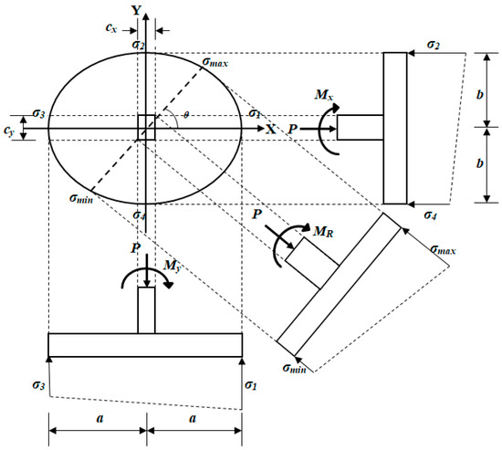
Figure 2.
Elliptical isolated footing. Here, σ1, σ2, σ3, and σ4 represent the soil pressures on the principal axes at the extreme fibers.
The general biaxial bending equation is expressed as follows:
where σ represents the soil pressure at any part of the base (kN/m2); P represents the unfactored axial load (kN); A represents the contact surface with the soil at the base (m2); Mx and My represent the unfactored moments on the X and Y axes (kN-m), respectively; Ix and Iy represent the moments of inertia on the X and Y axes (m4), respectively; and x and y represent the coordinates in the X and Y directions of the base (m), respectively.
Equation (1) assumes that the soil contact surface is completely compressed [1,49,50].
A resultant moment “MR” is assumed as follows:
The angle of inclination of the resultant moment on the X axis is expressed as follows:
Equation of the ellipse located at the origin is expressed as follows:
where a = total dimension of the elliptical on X axis, and b = total dimension of the elliptical on Y axis.
Substituting A = πab, Ix = πab3/4, and Iy = πa3b/4 into Equation (1), the soil pressure is obtained in a general way:
Substituting Equation (4) into Equation (5) to determine the soil pressure as a function of x, the following is obtained:
Deriving Equation (6) with respect to x to obtain the location of maximum and minimum pressures, the points are expressed as follows:
Equation (7) is substituted into Equation (4) to determine the values of ymax and ymin:
Now, substituting the corresponding coordinates of each critical point into Equation (5), the soil pressures on the elliptical footing are obtained:
where σmax and σmin are the maximum and minimum pressures, respectively.
2.1. Minimum Surface for an Elliptical Isolated Footing
The objective function Amin (minimum area) as follows:
The constraint functions appear in Equations (9) and (10), where 0 ≤ σmax and σmin ≤ σaasp (allowable soil pressure available to support all loads). The allowable soil pressure available to support all loads is calculated as the allowable soil pressure minus the concrete weight and minus the soil fill weight.
2.2. Minimum Cost for an Elliptical Isolated Footing
Now, Equation (5) is shown for the factored pressure σu in the function of the elliptical base coordinates. The general equation is expressed as follows:
where Pu = factored axial load (kN); Mxu = factored moment on the X axis (kN-m); and Myu = factored moment on the Y axis (kN-m). The factored loads and moments are obtained as follows: 1.2 the dead load or dead moment plus 1.6 the live load or live moment as the case may be, according to ACI [51].
The design of isolated footings is governed by moments, bending shear and punching shear according to ACI [51].
2.2.1. Moments
Figure 3 presents the critical sections for moments of an elliptical footing under biaxial bending according to ACI [51].
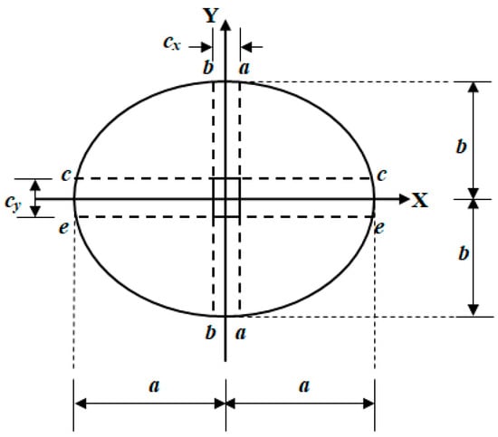
Figure 3.
Critical sections for moments.
The moments parallel to the X and Y axes are developed below.
The moment with respect to the “a” axis is expressed as follows:
where cx = side of the column parallel to the X axis.
The moment with respect to the “b” axis is expressed as follows:
The moment with respect to the “c” axis is expressed as follows:
where cy = side of the column parallel to the Y axis.
The moment with respect to the “e” axis is expressed as follows:
2.2.2. Bending Shear
Figure 4 shows the critical sections for bending shear of an elliptical footing under biaxial bending, appearing at a distance “d” (effective footing depth) from the column faces according to ACI [51].
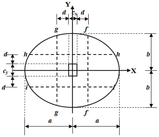
Figure 4.
Critical sections for bending shears.
The bending shear with respect to the “f” axis is expressed as follows:
The bending shear with respect to the “g” axis is expressed as follows:
The bending shear with respect to the “h” axis is expressed as follows:
The bending shear with respect to the “i” axis is expressed as follows:
2.2.3. Punching Shear
Figure 5 shows the critical perimeter for punching shear of an elliptical footing under biaxial bending, appearing at a distance “d/2” from the column faces according to ACI [51].
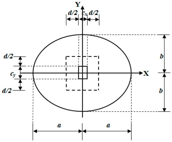
Figure 5.
Critical sections for punching shear.
The punching shear at the critical perimeter is expressed as follows:
2.2.4. Objective Function
The equation to determine the minimum total cost “Cmin” (dollars) is as follows:
where Cc = cost of concrete in USD per each cubic meter, Vc = volume of concrete in cubic meters, Cs = cost of steel in USD per each kilonewton of weight, Vs = volume of steel in cubic meters, and γs = steel density (78 kN/m3).
The reinforcing steel of the elliptical footing is obtained as follows. The footing is reinforced orthogonally, parallel to the main axes and an elliptical ring at a distance r (concrete cover in m) from the outer edge.
The steel area parallel to the X axis “Asx” and the steel area parallel to the Y axis “Asy” are expressed as follows:
where Asx is the largest area of Asxa and Asxb (steel areas in sections “a” and “b”), and Asy is the largest area of Asyc and Asye (steel areas in sections “c” and “e”). These areas are determined as follows:
where bwya, bwyb, bwxc, and bwxe are determined as follows:
The number of rods parallel to the X axis “nx” and the number of rods parallel to the Y axis “ny” are given as follows:
where as = cross-sectional steel area of the rod in the both directions.
where sx = separation of the rods parallel to the X axis, and sy = separation of the rods parallel to the Y axis.
The total lengths of the rods in the both directions are obtained as follows:
Note: Equations (37) and (38) are given from the location of the rods on the X and Y axes. Then, the following expression presents the length according to the spacing of the rods. The length of the rods parallel to the X axis is (length of the rods located on the positive part of the Y axis; these lengths must be multiplied by four to determine the total length of the rods located outside the X axis). The length of the rods parallel to the Y axis is (length of the rods located on the positive part of the X axis; these lengths must be multiplied by four to determine the total length of the rods located outside the Y axis).
The length of the rods around the perimeter of the ellipse “Le” is as follows:
where r = concrete cover.
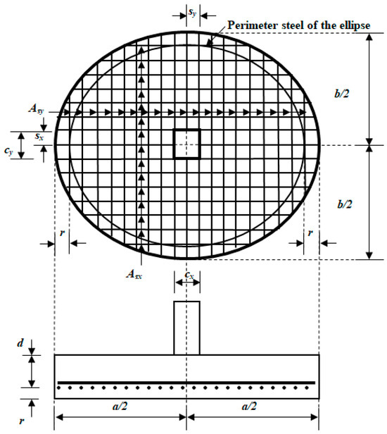
Figure 6.
Reinforcing steel for elliptical footing.
The volume of steel “Vs” is shown below:
The volume of concrete “Vc” is presented below:
Substituting Equations (40) and (41) into Equation (31) gives the following:
Now, substituting α = γsCs/Cc → γsCs = αCc into Equation (42) gives the following:
Substituting Equation (40) with their respective values of “Ly”, “Lx”, and “Le” into Equation (43) yields the following:
2.2.5. Constraint Functions
This subsection shows the equations provided by the code [51].
For the moments, the following is expressed [51]:
where fy = strength of the steel reinforcement in MPa, f’c = compressive strength of the concrete after 28 days in MPa, Asx = steel reinforcement in the X direction, Asy = steel reinforcement in the Y direction, and Øf (bending strength reduction factor) = 0.90.
Note: For Mua, As = Asxa and bw = bwya; for Mub, As = Asxb and bw = bwyb; for Muc, As = Asyc and bw = bwxc; for Mue, As = Asye and bw = bwxe.
For the shears, the following is expressed [51]:
where Øv (shear strength reduction factor) = 0.85.
Note: For Vuf, bws = bwsyf; for Vug, bws = bwsyg; for Vuh, bws = bwsxh; for Vui, bws = bwsxi. Here, bwsyf, bwsygb, bwsxh, and bwsxi are determined as follows:
For the punching, the following is expressed [51]:
where βc = long side of column/short side of column; b0 = perimeter of the critical punching shear section in m; αs = 20 for the corner column; αs = 30 for the edge column; and αs = 40 for the interior column.
For the percentages of steel, the following is expressed [51]:
where β1 = factor relating the depth of the equivalent rectangular compressive stress block to the depth of the neutral axis.
For the steel areas, the following is expressed [51]:
For the number of rods, the following is expressed [51]:
For the separations, the following is expressed [51]:
The new model is developed in two parts. The first part is used to estimate the minimum area, and the second part is used to determine the minimum cost. For the minimum area, the independent parameters are σaasp, P, Mx, and My, and the design variables are Amin, a, b, σmax, and σmin. For the minimum cost, the independent parameters are a, b, Pu, Mxu, and Myu, and the design variables are Cmin, d, Asx, Asy, ρx, and ρy.
The flowchart algorithm for the design procedure of an elliptical footing under the minimum cost criterion appears in Figure A1 (see Appendix A).
The flowchart for using Maple software (v.15) to design an elliptical footing under the minimum cost criterion appears in Figure A2 (see Appendix A).
3. Numerical Examples
Two numerical examples are presented, and each example shows five variants to determine the minimum cost of elliptical footings subjected to biaxial bending. The general data for the two examples are cx = cy = 40 cm, r = 7.5 cm, as = 5.07 cm2 (1Ø1”), σaasp = 200 kN/m2, f’c = 21 MPa, fy = 420 MPa, and α = 90.
The input data (P, Mx, My; these loads and moments should not be factored) for example 1 appear in Table 1. The output data (Pu, Mxu, Myu; these loads and moments must be factored) for example 1 are shown in Table 2.

Table 1.
Input data for example 1.

Table 2.
Output data for example 1.
The input data (P, Mx, My; these loads and moments should not be factored) for example 2 appear in Table 3. The output data (Pu, Mxu, Myu; these loads and moments must be factored) for example 2 are shown in Table 4.

Table 3.
Input data for example 2.

Table 4.
Output data for example 2.
4. Results
The proposed model (elliptical footing) compared with that of Luévanos-Rojas et al. [47] (circular footing) is verified as follows.
Note: The axes parallel to the X axis are the c and e axes for moments and the h and i axes for bending shears, and the axes parallel to the Y axis are the a and b axes for moments and the g and f axes for bending shears (proposed model). The axes parallel to the X axis are the a and b axes for moments and the f and g axes for bending shears, and the axes parallel to the Y axis are the c and e axes for moments and the h and i axes for bending shears (proposed model).
For factored pressure:
- Substituting a = D/2, b = D/2 into Equation (12) gives σu(x, y), and substituting ex = 0, ey = 0 into Equation (8) of the reference [47] gives σu(x, y); both are equal.
For moments:
- Substituting a = D/2, b = D/2 into Equation (14) gives Mua, and substituting ex = 0, ey = 0 into Equation (14) of the reference [47] gives Muc, Mua = Muc (both are parallel to the Y axis).
- Substituting a = D/2, b = D/2 into Equation (16) gives Mub, and substituting ex = 0, ey = 0 into Equation (16) of the reference [47] gives Mue, Mub = Mue (both are parallel to the Y axis).
- Substituting a = D/2, b = D/2 into Equation (18) gives Muc, and substituting ex = 0, ey = 0 into Equation (10) of the reference [47] gives Mua, Muc = Mua (both are parallel to the X axis).
- Substituting a = D/2, b = D/2 into Equation (20) gives Mue, and substituting ex = 0, ey = 0 into Equation (12) of the reference [47] gives Mub, Mue = Mub (both are parallel to the X axis).
For bending shears:
- Substituting a = D/2, b = D/2 into Equation (21) gives Vuf, and substituting ex = 0, ey = 0 into Equation (22) of the reference [47] gives Vubh, Vuf = Vubh (both are parallel to the Y axis).
- Substituting a = D/2, b = D/2 into Equation (23) gives Vug, and substituting ex = 0, ey = 0 into Equation (24) of the reference [47] gives Vubi, Vug = Vubi (both are parallel to the Y axis).
- Substituting a = D/2, b = D/2 into Equation (25) gives Vuh, and substituting ex = 0, ey = 0 into Equation (18) of the reference [47] gives Vubf, Vuh = Vubf (both are parallel to the X axis).
- Substituting a = D/2, b = D/2 into Equation (27) gives Vui, and substituting ex = 0, ey = 0 into Equation (20) of the reference [47] gives Vubg, Vui = Vubg (both are parallel to the X axis).
For punching shear:
- Substituting a = D/2, b = D/2 into Equation (29) gives Vup, and substituting ex = 0, ey = 0, x1 = cx/2 + d/2, x2 = −cx/2 − d/2, y1 = cy/2 + d/2, y2 = −cy/2 − d/2 into Equation (26) of the reference [47] gives Vup, both are equal.
Also, the proposed model can be verified by continuity as follows.
For moments:
- Integrating Equation (13) from zero to “a” and obtaining moments at the free end gives Mua = 0.
- Integrating Equation (15) from “−a” to “a” and obtaining moments at the free end gives Mub = 0.
- Integrating Equation (13) from zero to “a” and obtaining moments at the center of footing gives Mua = −2Pua/3π − Myu/2. Integrating Equation (15) from “−a” to zero and obtaining moments at the center of footing gives Mub = 2Pua/3π + Myu/2. Therefore, Mua and Mub are the same, but in the opposite sense. Thus, continuity is guaranteed.
- Integrating Equation (17) from zero to “b” and obtaining moments at the free end gives Muc = 0.
- Integrating Equation (19) from “−b” to “b” and obtaining moments at the free end gives Mue = 0.
- Integrating Equation (17) from zero to “b” and obtaining moments at the center of footing gives Muc = −2Pub/3π − Mxu/2. Integrating Equation (19) from “−b” to zero and obtaining moments at the center of footing gives Mue = 2Pub/3π + Mxu/2. Therefore, Muc and Mue are the same, but in the opposite sense. Thus, continuity is guaranteed.
For bending shears:
- Integrating Equation (21) from zero to “a” and obtaining the bending shear at the free end gives Vuf = 0.
- Integrating Equation (23) from “−a” to “a” and obtaining the bending shear at the free end gives Vug = 0.
- Integrating Equation (21) from zero to “a” and obtaining the bending shear at the center of footing gives Vuf = −Pu/2 − 8Myu/3aπ. Integrating Equation (23) from “−a” to zero and obtaining the bending shear at the center of footing gives Vug = Pu/2 + 8Myu/3aπ. Therefore, Vuf and Vug are the same, but in the opposite sense. Thus, continuity is guaranteed.
- Integrating Equation (25) from zero to “b” and obtaining the bending shear at the free end gives Vuh = 0.
- Integrating Equation (27) from “−b” to “b” and obtaining the bending shear at the free end gives Vui = 0.
- Integrating Equation (25) from zero to “b” and obtaining the bending shear at the center of footing gives Vuh = −Pu/2 − 8Mxu/3bπ. Integrating Equation (27) from “−b” to zero and obtaining the bending shear at the center of footing gives Vui = Pu/2 + 8Mxu/3bπ. Therefore, Vuh and Vui are the same, but in the opposite sense. Thus, continuity is guaranteed.
For punching shear:
- Integrating Equation (29) from zero to “a” in the X direction and from zero to “b” in the Y direction to obtain the punching shear at the free ends of the footing results in zero.
Table 2 and Table 4 show the following. For examples A.1, B.1, C.1, D.1, C.2, D.2, and E.2 the minimum pressure governs, and for examples E.1, A.2, and B.2 the maximum pressure governs.
Table 2 presents the following. When Myu is reduced, a, Amin, and Cmin decrease; b is the same for all examples; Asx, Asy, and ρx decrease up to Myu = 400 kN-m and subsequently increase (ρx is the same for examples D.1 and E.1); ρy is the same for examples A.1 and B.1, then increases up to Myu = 400 kN-m, and subsequently decreases; σmax, σmin increase; sx increases up to Myu = 680 kN-m and then decreases; sy increases up to Myu = 960 kN-m and then decreases; d tends to increase. Example C.1 shows a circular footing.
Table 4 shows the following. When Pu is reduced, a, b, Amin, Cmin decrease up to Pu = 1800 kN and subsequently increase; Asx decreases up to Pu = 1800 kN, then increases up to Pu = 1520 kN, then decreases up to Pu = 1240 kN, and then increases; Asy increases up to Pu = 1520 kN, then decreases up to Pu = 1240 kN, and then increases; σmax increases up to Pu = 1800 kN and then decreases; σmin decreases for all examples; ρy increases up to Pu = 1800 kN, then decreases up to Pu = 1520 kN, then increases up to Pu = 1240 kN, and then decreases; ρx is the same for examples A.2, B.2, C.2, and D.2 and then increases; sx increases up to Pu = 1240 kN and then decreases; sy increases up to Pu = 1520 kN, then decreases up to Pu = 1240 kN, and then increases; and d tends to decrease.
According to the results, this model can be applied to circular footings with axial load located at the center of gravity of the footing as shown in problem C.1 of Table 2.
Table 5 shows the results of problem 2 using the equations for circular footings proposed by Luévanos-Rojas et al. [47]; this example is solved using ex (eccentricity in the X direction) = 0, ey (eccentricity in the Y direction) = 0, and the same input data as example 2 (see Table 3).

Table 5.
Output data of example 2 for circular footings.
Table 5 presents the following. When Pu is reduced, D, Asx, Asy, Amin, and Cmin decrease up to Pu = 1800 kN and subsequently increase; σmax and σmin decrease for all examples; ρx is the same for all examples; ρy increases up to Pu = 1800 kN, then decreases up to Pu = 1240 kN, and then it remains constant; sx tends to increases; sy decreases up to Pu = 1800 kN and then increases; d tends to decrease. For examples A.2, B.2 the maximum pressure prevails. For examples, C.2, D.2, and E.2 the minimum pressure prevails.
Figure 7 shows the comparison of the minimum area in contact with the ground and minimum design cost between EF (elliptical footings) and CF (circular footings) of example 2 (see Table 4 and Table 5).
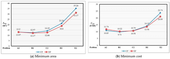
Figure 7.
Comparison between elliptical footings and circular footings.
Figure 7a presents the following. The minimum area is smaller for elliptical footings than for circular footings in all problems. The greatest savings occur in E2 with a saving of 11.60% using the elliptical footings model.
Figure 7b shows the following. The lowest minimum cost appears in examples A.2; B.2 for circular footings; and in examples C.2, D.2, and E.2 for elliptical footings. The greatest savings occur in A2 with a saving of 7.58% using the circular footings model. The greatest savings occur in E2 with a saving of 11.58% using the elliptical footings model.
5. Conclusions
This research shows the mathematical calculation for the optimal cost design of elliptical footings subjected to biaxial bending, assuming that the footing rests on elastic soils, the footing is rigid, and the pressure diagram is linear.
The new model for elliptical footings is shown in two parts. The first part is used to determine the minimum area, and the second part is used to obtain the minimum cost. For the minimum area, the independent parameters are σaasp, P, Mx, and My, and the design variables are Amin, a, b, σmax, and σmin. For the minimum cost, the independent parameters are a, b, Pu, Mxu, and Myu, and the design variables are Cmin, d, Asx, Asy, ρx, and ρy.
The contributions of this paper are as follows:
- (1)
- There is no literature on the subject of elliptical footings since the closest are circular footings; therefore, it is an innovative topic.
- (2)
- The moments, bending shears, and punching shear are verified by equilibrium (see Section 4).
- (3)
- The new model for elliptical footings can be applied to other building standards, taking into account the moments, bending shears, and punching shear that must be resisted.
- (4)
- When the factored moment about the Y axis “Myu” is reduced, the minimum area “Amin” and the minimum cost “Cmin” are reduced (see Table 2).
- (5)
- (6)
- The minimum area is smaller for elliptical footings than for circular footings in all problems (see Figure 7a).
- (7)
- (8)
- (9)
- The elliptical footing model presents a saving of 11.60% in the minimum area and 11.58% in the minimum cost for E2 compared to the circular footing model (see Figure 7).
This paper presents, in detail, the mathematical equations of moments, bending shear, and punching shear, as well as the optimization algorithms, which is its main advantage over other works.
Suggestions for future research may include mathematical calculations for the cost-optimal design of elliptical footings working with the resulting moment only and locating the principal axes where the resulting moment appears, that is, rotating the principal axes; another investigation could be considering that the surface in contact with the ground works partially in compression.
Author Contributions
Conceptualization, A.L.-R. and E.R.D.-G.; Methodology, A.L.-R.; Software, G.S.-H.; Validation, E.R.D.-G., V.M.M.-L. and A.E.L.-G.; Formal Analysis, V.M.M.-L.; Investigation, A.L.-R.; Resources, G.S.-H.; Data Curation, V.M.M.-L.; Writing—Original Draft Preparation, A.E.L.-G.; Writing—Review & Editing, A.E.L.-G.; Visualization, G.S.-H.; Supervision, A.L.-R.; Project Administration, E.R.D.-G.; Funding Acquisition, A.E.L.-G. All authors have read and agreed to the published version of the manuscript.
Funding
The research was funded by the Universidad Autónoma de Coahuila and Universidad Veracruzana, Mexico.
Data Availability Statement
Data are contained within the article.
Acknowledgments
The research described in this work was developed at the Universidad Autónoma de Coahuila and Universidad Veracruzana, Mexico.
Conflicts of Interest
The authors declare no conflict of interest.
Appendix A
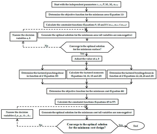
Figure A1.
Flowchart for the minimum cost design procedure for an elliptical footing.
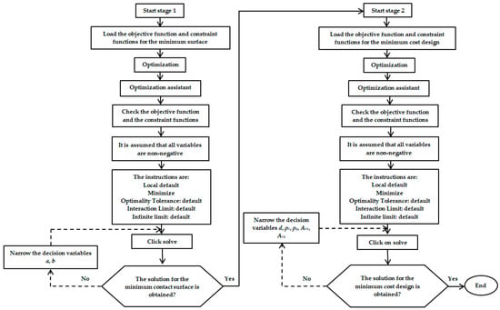
Figure A2.
Flowchart for using Maple software for the minimum cost design of an elliptical footing.
References
- Bowles, J.E. Foundation Analysis and Design; McGraw-Hill: New York, NY, USA, 2001. [Google Scholar]
- Shahin, M.A.; Cheung, E.M. Stochastic design charts for bearing capacity of strip footings. Geomech. Eng. 2011, 3, 153–167. [Google Scholar] [CrossRef]
- Dixit, M.S.; Patil, K.A. Experimental estimate of Nγ values and corresponding settlements for square footings on finite layer of sand. Geomech. Eng. 2013, 5, 363–377. [Google Scholar] [CrossRef]
- ErzÍn, Y.; Gul, T.O. The use of neural networks for the prediction of the settlement of pad footings on cohesionless soils based on standard penetration test. Geomech. Eng. 2013, 5, 541–564. [Google Scholar] [CrossRef]
- Colmenares, J.E.; Kang, S.-R.; Shin, Y.-J.; Shin, J.-H. Ultimate bearing capacity of conical shell foundations. Struct. Eng. Mech. 2014, 52, 507–523. [Google Scholar] [CrossRef]
- Cure, E.; Sadoglu, E.; Turker, E.; Uzuner, B.A. Decrease trends of ultimate loads of eccentrically loaded model strip footings close to a slope. Geomech. Eng. 2014, 6, 469–485. [Google Scholar] [CrossRef]
- Fattah, M.Y.; Yousif, M.A.; Al-Tameemi, S.M.K. Effect of pile group geometry on bearing capacity of piled raft foundations. Struct. Eng. Mech. 2015, 54, 829–853. [Google Scholar] [CrossRef]
- Uncuoğlu, E. The bearing capacity of square footings on a sand layer overlying clay. Geomech. Eng. 2015, 9, 287–311. [Google Scholar] [CrossRef]
- Anil, Ö.; Akbaş, S.O.; BabagĪray, S.; Gel, A.C.; Durucan, C. Experimental and finite element analyses of footings of varying shapes on sand. Geomech. Eng. 2017, 12, 223–238. [Google Scholar] [CrossRef]
- Khatri, V.N.; Debbarma, S.P.; Dutta, R.K.; Mohanty, B. Pressure-settlement behavior of square and rectangular skirted footings resting on sand. Geomech. Eng. 2017, 12, 689–705. [Google Scholar] [CrossRef]
- Mohebkhah, A. Bearing capacity of strip footings on a stone masonry trench in clay. Geomech. Eng. 2017, 13, 255–267. [Google Scholar] [CrossRef]
- Zhang, W.-X.; Wu, H.; Hwang, H.-J.; Zhang, J.-Y.; Chen, B.; Yi, W.-J. Bearing behavior of reinforced concrete column-isolated footing substructures. Eng. Struct. 2019, 200, 109744. [Google Scholar] [CrossRef]
- Turedi, Y.; Emirler, B.; Ornek, M.; Yildiz, A. Determination of the bearing capacity of model ring footings: Experimental and numerical investigations. Geomech. Eng. 2019, 18, 29–39. [Google Scholar] [CrossRef]
- Gnananandarao, T.; Khatri, V.N.; Dutta, R.K. Bearing capacity and settlement prediction of multi-edge skirted footings resting on sand. Ing. Investig. 2020, 40, 9–21. [Google Scholar] [CrossRef]
- Gör, M. Analyzing the bearing capacity of shallow foundations on two-layered soil using two novel cosmology-based optimization techniques. Smart Struct. Syst. 2022, 29, 513–522. [Google Scholar] [CrossRef]
- Hu, D.; Hu, Y.; Hu, R.; Tan, Z.; Ni, P.; Chen, Y.; Xiang, X.; Li, Y.; Liu, J. Machine Learning–Finite Element Mesh Optimization-Based Modeling and Prediction of Excavation-Induced Shield Tunnel Ground Settlement. Int. J. Comput. Methods 2024, 22, 2450066. [Google Scholar] [CrossRef]
- Yin, Q.; Xin, T.; Zhenggang, H.; Minghua, H. Measurement and Analysis of Deformation of Underlying Tunnel Induced by Foundation Pit Excavation. Adv. Civil Eng. 2023, 1, 8897139. [Google Scholar] [CrossRef]
- Li, Z.-Q.; Nie, L.; Yiguo Xue, Y.; Li, W.; Fan, K. Model Testing on the Processes, Characteristics, and Mechanism of Water Inrush Induced by Karst Caves Ahead and Alongside a Tunnel. Rock Mech. Rock Eng. 2025, 58, 5363–5380. [Google Scholar] [CrossRef]
- Zhang, J.; Li, Y.; Zhang, C. Pounding induced overturning resistance of FPB-isolated structures considering soil-structure-interactions. Soil Dyn. Earthq. Eng. 2024, 177, 108416. [Google Scholar] [CrossRef]
- Ren, S.-P.; Chen, X.; Ren, Z.-L.; Cheng, P.; Liu, Y. Large-deformation modelling of earthquake-triggered landslides considering non-uniform soils with a stratigraphic dip. Comput. Geotech. 2023, 159, 105492. [Google Scholar] [CrossRef]
- Liu, Y.; Chen, X.; Hu, M. Three-dimensional large deformation modeling of landslides in spatially variable and strain-softening soils subjected to seismic loads. Can. Geotech. J. 2023, 60, 426–437. [Google Scholar] [CrossRef]
- Chaabani, W.; Remadna, M.S.; Abu-Farsakh, M. Numerical Modeling of the Ultimate Bearing Capacity of Strip Footings on Reinforced Sand Layer Overlying Clay with Voids. Infrastructures 2023, 8, 3. [Google Scholar] [CrossRef]
- Vitone, D.M.A.; Valsangkar, A.J. Stresses from loads over rectangular areas. J. Geotech. Geoenviron. 1986, 112, 961–964. [Google Scholar] [CrossRef]
- Michalowski, R.L. Upper-bound load estimates on square and rectangular footings. Géotechnique 2001, 51, 787–798. [Google Scholar] [CrossRef]
- Özmen, G. Determination of base stresses in rectangular footings under biaxial bending. Teknik Dergi Digest 2011, 22, 1519–1535. Available online: https://dergipark.org.tr/tr/download/article-file/136568 (accessed on 1 May 2025).
- Aydogdu, I. New Iterative method to Calculate Base Stress of Footings under Biaxial Bending. Int. J. Eng. Appl. Sci. 2016, 8, 40–48. [Google Scholar] [CrossRef][Green Version]
- Girgin, K. Simplified formulations for the determination of rotational spring constants in rigid spread footings resting on tensionless soil. JCEM 2017, 23, 464–474. [Google Scholar] [CrossRef]
- Al-Gahtani, H.J.; Adekunle, S.K. A boundary-type approach for the computation of vertical stresses in soil due to arbitrarily shaped foundations. World J. Eng. 2019, 16, 419–426. [Google Scholar] [CrossRef]
- Rawat, S.; Mittal, R.K.; Muthukumar, G. Isolated Rectangular Footings under Biaxial Bending: A Critical Appraisal and Simplified Analysis Methodology. Pract. Period. Struct. Des. Const. 2020, 25, 04020011. [Google Scholar] [CrossRef]
- López-Machado, N.A.; Perez, G.; Castro, C.; Perez, J.C.V.; López-Machado, L.J.; Alviar-Malabet, J.D.; Romero-Romero, C.A.; Guerrero-Cuasapaz, D.P.; Montesinos-Machado, V.V. A Structural Design Comparison Between Two Reinforced Concrete Regular 6-Level Buildings using Soil-Structure Interaction in Linear Range. Ing. Investig. 2022, 42, e86819. [Google Scholar] [CrossRef]
- Lezgy-Nazargah, M.; Mamazizi, A.; Khosravi, H. Analysis of shallow footings rested on tensionless foundations using a mixed finite element model. Struct. Eng. Mech. 2022, 81, 379–394. [Google Scholar] [CrossRef]
- Teng, W.C. Foundation Design; Prentice-Hall Inc.: New Delhi, India, 1979. [Google Scholar]
- Highter, W.H.; Anders, J.C. Dimensioning footings subjected to eccentric loads. J. Geotech. Geoenviron. 1985, 111, 659–665. [Google Scholar] [CrossRef]
- Galvis, F.A.; Smith-Pardo, P.J. Axial load biaxial moment interaction (PMM) diagrams for shallow foundations: Design aids, experimental verification, and examples. Eng. Struct. 2020, 213, 110582. [Google Scholar] [CrossRef]
- Rodriguez-Gutierrez, J.A.; Aristizabal-Ochoa, J.D. Rigid spread footings resting on soil subjected to axial load and biaxial bending. I: Simplified analytical method. Int. J. Geomech. 2013, 13, 109–119. [Google Scholar] [CrossRef]
- Rodriguez-Gutierrez, J.A.; Aristizabal-Ochoa, J.D. Rigid spread footings resting on soil subjected to axial load and biaxial bending. II: Design aids. Int. J. Geomech. 2013, 13, 120–131. [Google Scholar] [CrossRef]
- Maheshwari, P.; Khatri, S. Influence of inclusion of geosynthetic layer on response of combined footings on stone column reinforced earth beds. Geomech. Eng. 2012, 4, 263–279. [Google Scholar] [CrossRef]
- Konapure, C.G.; Vivek, B. Analysis of Combined rectangular footing by Winkler’s Model and Finite Element Method. Int. JEIT 2013, 3, 128–132. Available online: https://www.ijeit.com/Vol%203/Issue%205/IJEIT1412201311_21.pdf (accessed on 1 January 2020).
- Vivek, B.; Arkal, L.S.; Bandgar, R.V.; Kalekhan, F.A.S. Comparative Study on Conventional and Simplified Elastic Analysis of Rectangular Combined Footing. Int. J. Res. Eng. Technol. 2014, 3, 422–427. Available online: https://ijret.org/volumes/2014v03/i04/IJRET20140304076.pdf (accessed on 1 May 2025).
- Ravi Kumar Reddy, C.; Satish Kumar, M.; Kondala Rao, M.; Gopika, N. Numerical Analysis of Rectangular Combined Footings Resting on Soil for Contact Pressure. Int. J. Civil Engi. Technol. 2018, 9, 1425–1431. Available online: http://iaeme.com/Home/issue/IJCIET?Volume=9&Issue=9 (accessed on 31 January 2025).
- Kashani, A.R.; Camp, C.V.; Akhani, M.; Ebrahimi, S. Optimum design of combined footings using swarm intelligence-based algorithms. Adv. Eng. Soft. 2022, 169, 103140. [Google Scholar] [CrossRef]
- Al-Douri, E.M.F. Optimum design of trapezoidal combined footings. Tikrit J. Eng. Sci. 2007, 14, 85–115. [Google Scholar] [CrossRef]
- Luévanos-Rojas, A. Optimization for trapezoidal combined footings: Optimal design. Adv. Concr. Constr. Int. J. 2023, 16, 21–34. [Google Scholar] [CrossRef]
- Moreno-Landeros, V.M.; Luévanos-Rojas, A.; Santiago-Hurtado, G.; López-León, L.D.; Olguin-Coca, F.J.; López-León, A.L.; Landa-Gómez, A.E. Optimal Cost Design of RC T-Shaped Combined Footings. Buildings 2024, 14, 3688. [Google Scholar] [CrossRef]
- Aishwarya, K.M.; Balaji, N.C. Analysis and design of eccentrically loaded corner combined footing for rectangular columns. In Proceedings of the International Conference on Advances in Sustainable Construction Materials, Guntur, India, 18–19 March 2022. [Google Scholar] [CrossRef]
- Luévanos-Rojas, A.; Santiago-Hurtado, G.; Moreno-Landeros, V.M.; Olguin-Coca, F.J.; López-León, L.D.; Diaz-Gurrola, E.R. Mathematical Modeling of the Optimal Cost for the Design of Strap Combined Footings. Mathematics 2024, 12, 294. [Google Scholar] [CrossRef]
- Luévanos-Rojas, A.; Moreno-Landeros, V.M.; Santiago-Hurtado, G.; Olguin-Coca, F.J.; López-León, L.D.; Baltazar-Zamora, M.A.; Diaz-Gurrola, E.R. Mathematical Modeling for the Optimal Cost Design of Circular Isolated Footings with Eccentric Column. Mathematics 2024, 12, 733. [Google Scholar] [CrossRef]
- Elhanash, M.; Elsherif, A.K.; Aref, A.; Nagy, N.M. New analytical method for optimum design of circular and elliptical footings. Adv. Comput. Des. 2025, 10, 151–167. [Google Scholar]
- Das, B.M.; Sordo-Zabay, E.; Arrioja-Juárez, R. Principios de Ingeniería de Cimentaciones; Cengage Learning Latín América: Mexico City, Mexico, 2006. [Google Scholar]
- McCormac, J.C.; Brown, R.H. Design of Reinforced Concrete; John Wiley & Sons, Inc.: Mexico City, Mexico, 2014. [Google Scholar]
- ACI 318-19; Building Code Requirements for Structural Concrete and Commentary. American Concrete Institute: Farmington Hills, MI, USA, 2019.
Disclaimer/Publisher’s Note: The statements, opinions and data contained in all publications are solely those of the individual author(s) and contributor(s) and not of MDPI and/or the editor(s). MDPI and/or the editor(s) disclaim responsibility for any injury to people or property resulting from any ideas, methods, instructions or products referred to in the content. |
© 2025 by the authors. Licensee MDPI, Basel, Switzerland. This article is an open access article distributed under the terms and conditions of the Creative Commons Attribution (CC BY) license (https://creativecommons.org/licenses/by/4.0/).