1. Introduction
Underwater vehicles are widely used in marine environment exploration marine resource development, and underwater tasks in confined water areas, such as welding operations [
1,
2,
3,
4]. To meet the demand for high-precision motion control of underwater vehicles, researchers have proposed various control algorithms, such as adaptive control, model predictive control, neural-network control, among others [
5,
6,
7,
8,
9]. However, in complex fluid environments, energy efficiency is also of great importance. As a result, the design of propulsion systems for underwater vehicles, especially thruster configurations and thrust allocation strategies, has emerged as a critical area of research. Modern underwater vehicles must navigate hydrodynamic uncertainties, manage limited onboard energy reserves, and maintain operational integrity even in the event of thruster failures. While advancements in control theory and optimization have improved propulsion system performance, significant challenges persist in harmonizing fault tolerance, energy efficiency, and computational practicality [
10,
11].
Thruster configuration design directly impacts underwater vehicles’ maneuverability, fault tolerance, and energy consumption. Conventional configurations, such as the 6 DOF setups with orthogonal thrusters, prioritize basic motion control but lack redundancy to address thruster malfunctions [
12,
13,
14]. Kadiyam et al. [
15,
16] proposed two different actuator configuration schemes for underwater autonomous vehicles, fixed thrusters and vector thrusters, and verified the performance differences between the two configurations through trajectory tracking. Xu et al. [
17] proposed a general thruster configuration solution, using system energy consumption as a comprehensive model and thruster saturation input as constraints, employing QP to approximately solve the optimal solution for the non-convex optimization problem. Tanakitkorn et al. [
18] proposed a convertible thruster configuration scheme, which can maintain high performance in both path tracking and dynamic hovering scenarios.
However, redundant systems increase the complexity of thrust allocation. Traditional methods (such as the least squares method based on pseudo-inverse) address redundancy by minimizing thrust errors, but they often neglect energy consumption and thruster saturation, resulting in inefficiency or instability [
19]. In recent years, researchers have proposed methods such as weighted pseudoinverse, task-priority approach, and nonlinear optimization for solving the control allocation problem [
20,
21,
22]. To address these limitations, optimization-based thrust allocation strategies, particularly quadratic programming, have gained traction. QP frameworks enable the integration of energy minimization objectives and physical constraints, such as thruster saturation, into the optimization process. Rethfeldt et al. [
23] applied the thrust allocation method based on quadratic programming for an underwater vehicle equipped with variable buoyancy systems, in order to optimize the use of actuators.
There are also certain limitations in the thrust allocation problem based on quadratic programming. For instance, the structural constraints of thrusters may exhibit nonlinearity, which means that such constraints will not constitute a convex optimization problem. We can transform the QP optimization problem into a sequential quadratic programming (SQP) problem. Zheng et al. [
24] proposed a novel thruster configuration method and applied the SQP algorithm to solve the thrust allocation problem. Through simulation comparisons with commonly used configuration methods, they verified that the proposed method has superior performance in terms of energy consumption. Liang et al. [
25] addressed the saturation phenomenon issue in over-actuated underwater robots by modifying the objective function of the SQP algorithm, thereby overcoming the optimization instability problem in SQP. Yuan et al. [
26] proposed an efficient nonlinear saturation-constrained sequential quadratic programming algorithm to address the fault-tolerant control problem of thruster faults in an over-actuated underwater vehicle. Through simulation, this algorithm effectively solved the fault-tolerant trajectory tracking control problem for the vehicle. However, compared with the SQP method, the QP method is better suited to meet the real-time requirements of the system [
27,
28,
29].
Unlike underwater vehicles equipped with steerable thrusters, the over-actuated underwater vehicles in this paper adopt a redundant layout scheme of fixed thrusters. Since the inequality constraints are linear and the objective function is quadratic, the QP method can be employed to achieve optimization calculations and meet real-time requirements. Taking into account the potential for electronic components to be damaged by high temperatures, the thrust allocation strategy needs to minimize the energy consumption of the thrusters while still satisfying the control commands.
In summary, for the thruster configuration and thrust allocation problem of underwater vehicles, this paper proposes a thruster spatial vector layout method and a QP thrust allocation strategy. It ensures that the underwater vehicle can still maintain certain motion performance even in the case of thruster failure and achieves optimal energy consumption in thrust distribution under the constraints of thrust saturation and real-time requirements. First, the mathematical model of the vector propulsion system is established to obtain the relationship between the thruster thrust of the underwater vehicle and the resultant force acting on the vehicle body in 6 DOF. Then, the fault-tolerant performance of the underwater vehicle is analyzed. Next, a QP redundant thrust allocation strategy is provided. Finally, simulation is used to verify the effectiveness and feasibility of the QP thrust allocation strategy. The results show that, compared to the LS allocation, the thrust allocation under the QP strategy effectively avoids thruster thrust saturation and achieves optimal energy consumption in thrust distribution, providing an optimized solution for the high-precision motion control of the underwater vehicle.
The remainder of this paper is organized as follows:
Section 2 introduces the thruster configuration for the underwater vehicle;
Section 3 is dedicated to the fault-tolerant performance analysis of the underwater vehicle;
Section 4 presents the QP-based thrust allocation strategy;
Section 5 validates the method through comparative simulations;
Section 6 analyzes the critical advantages of the QP-based thrust allocation strategy; and
Section 7 discusses implications for future research.
2. Thruster Configuration
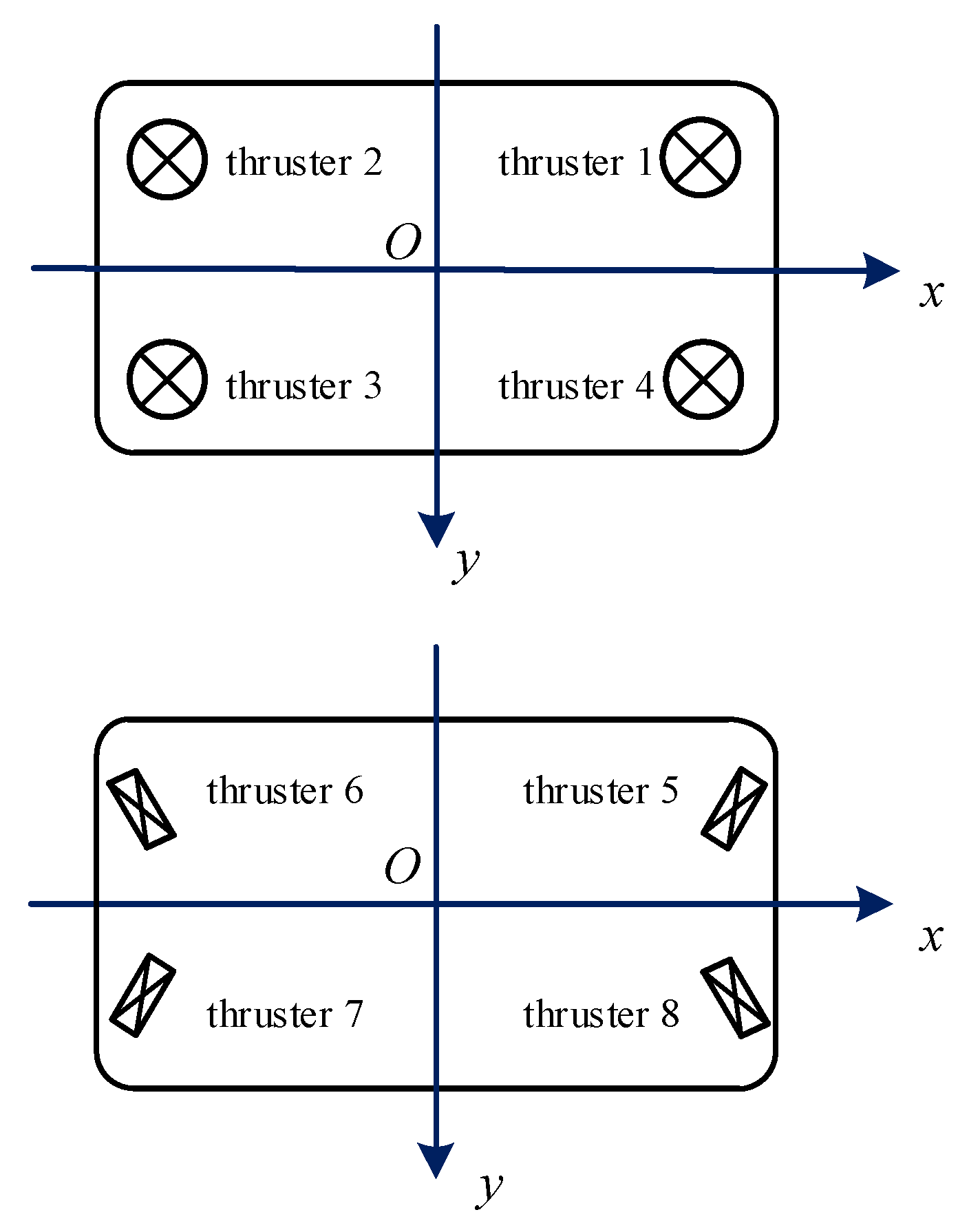
In order to meet the 6 DOF spatial motion requirements of the operational underwater vehicle, the thrusters are configured on the underwater vehicle, as shown in
Figure 1. Among them, thrusters 1, 2, 3, and 4 are arranged vertically parallel to the
z-axis to achieve the vehicle’s roll, pitch, and heave motions; thrusters 5, 6, 7, and 8 are arranged parallel to the
xOy plane, each at a 30-degree angle to the
x-axis, to achieve the vehicle’s yaw, surge, and sway motions. The position vectors and thrust vectors of the 8 thrusters are shown in
Table 1.
The role of thrust allocation is to distribute the 6 DOF control forces and torques sent by the upper controller of the vehicle to the various thrusters in the propulsion system. The thrusters output thrust according to the results obtained from the thrust allocation optimization. To achieve this, we establish the dynamic equations of the underwater vehicle [
30], as shown in Equation (1).
where
M represents the sum of the inertia matrix and the added mass matrix,
represents the Coriolis force and centripetal force matrix,
represents the viscous hydrodynamic coefficient matrix of the underwater vehicle,
represents the matrix of restoring forces generated by the underwater vehicle’s weight and buoyancy, and
τ represents the control inputs.
is calculated from the thrust vector,
, and the configuration matrix,
, as shown in Equation (2).
where
,
represents the output thrust of the
i-th thruster. The configuration matrix,
, is determined by the position vector and thrust vector of the thrusters. The parameters of the vectors are shown in
Table 1.
The vector representing the force and torque applied by the
i-th thruster on the vehicle can be written as follows:
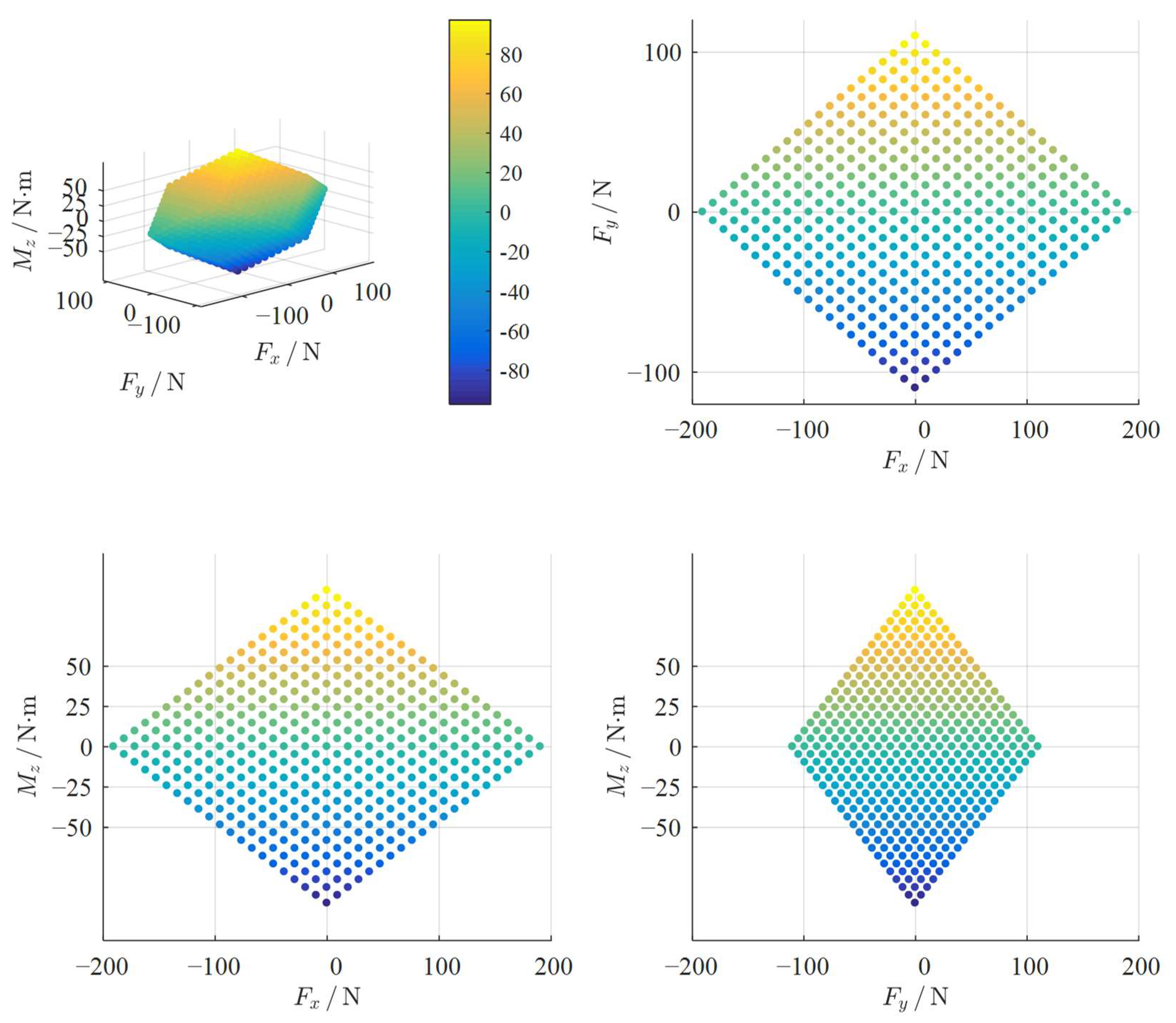
In the operation of the underwater vehicle, the thrust output of the thrusters may exhibit saturation phenomena, meaning each thruster has a maximum thrust limit. The maximum forward and reverse thrust of the thrusters are both 55 N.
According to Equations (2) and (4), the thrust saturation condition of vertically arranged thrusters under unconstrained thrust distribution is shown in
Figure 2, while the thrust saturation condition of four horizontally arranged thrusters is shown in
Figure 3. In
Figure 2 and
Figure 3, the three-dimensional point cloud region represents areas where thrust saturation has not occurred, the boundary points are those near saturation, and the remaining areas indicate thrust saturation.
3. Fault-Tolerance Performance Analysis
The thrusters configured on the underwater vehicle are the vehicle’s only power output devices, and their performance directly determines the underwater vehicle’s mobility and operational stability. This redundant configuration increases the system’s reliability and fault tolerance. When a thruster on the underwater vehicle fails, the vehicle can still maintain certain movement capabilities. For simplicity in analysis, we will not perform thrust allocation optimization on the thrusters but instead use the pseudoinverse of the configuration matrix, i.e., the LS method, for calculations. Below is a brief introduction to the LS method of the underwater vehicle’s thruster configuration matrix.
By Equation (2), we can obtain that the thrust vector of the thruster as
The pseudoinverse
of matrix
is defined as
We only need to calculate whether the configuration matrix
is a full-rank matrix to determine if the underwater vehicle has any uncontrolled degrees of freedom and, thus, assess the impact of thruster failure on the vehicle’s movement. The vehicle’s fault tolerance performance is shown in
Table 2.
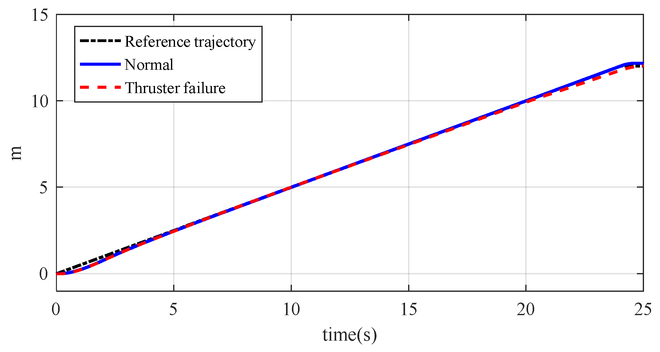
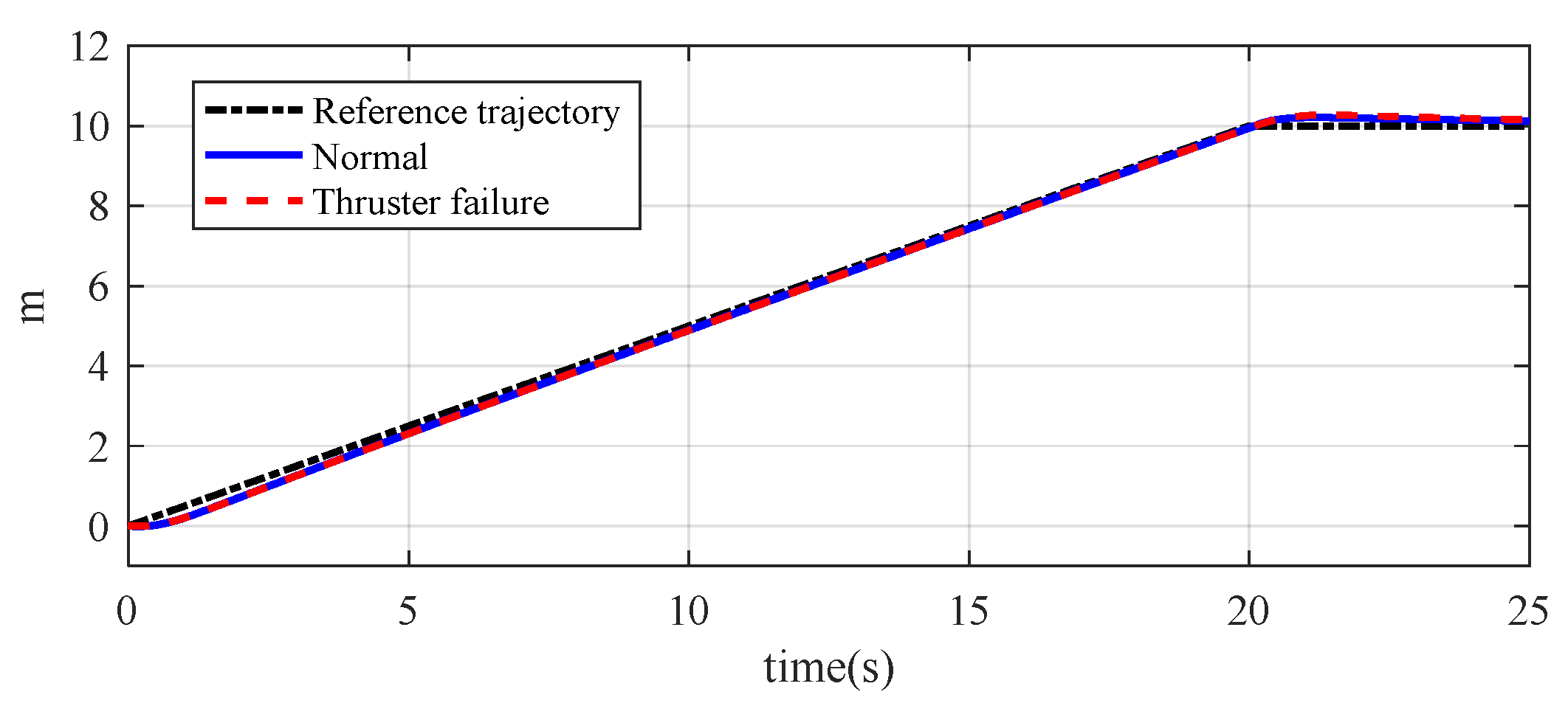
The impact of thruster failure on the underwater vehicle’s trajectory and the output thrust of other thrusters is verified through simulation. To ensure comprehensiveness, a trajectory is designed for the underwater vehicle such that both vertically and horizontally arranged thrusters are in operation. In this case, the vehicle is required to simultaneously perform heave and surge motions with a speed of 0.5 m/s, and the endpoint of the trajectory is set at the coordinates (10, 0, 12). We assume that the thruster 1 fails after 10 s of operation, and the changes in the underwater vehicle’s trajectory and the output thrust of the thrusters are observed, as shown in
Figure 4,
Figure 5,
Figure 6 and
Figure 7.
In
Figure 4 and
Figure 5, the failure of the 1st thruster has no impact on the vehicle’s trajectory tracking, and the trajectory almost overlaps with the trajectory when the thruster is working normally and the reference trajectory.
In
Figure 6, we can observe that the output of T1 drops to 0 after 10 s due to the failure, and the output of the diagonally arranged thruster 3 also decreases significantly. This is to prevent the generation of a torque that could cause overturning due to the thrust difference with the 1st thruster. The output thrust of the 2nd thruster and the 4th thruster increases instantaneously to ensure sufficient output to complete the underwater vehicle’s reference trajectory. Meanwhile, the output of the horizontally arranged thrusters does not show any significant change.
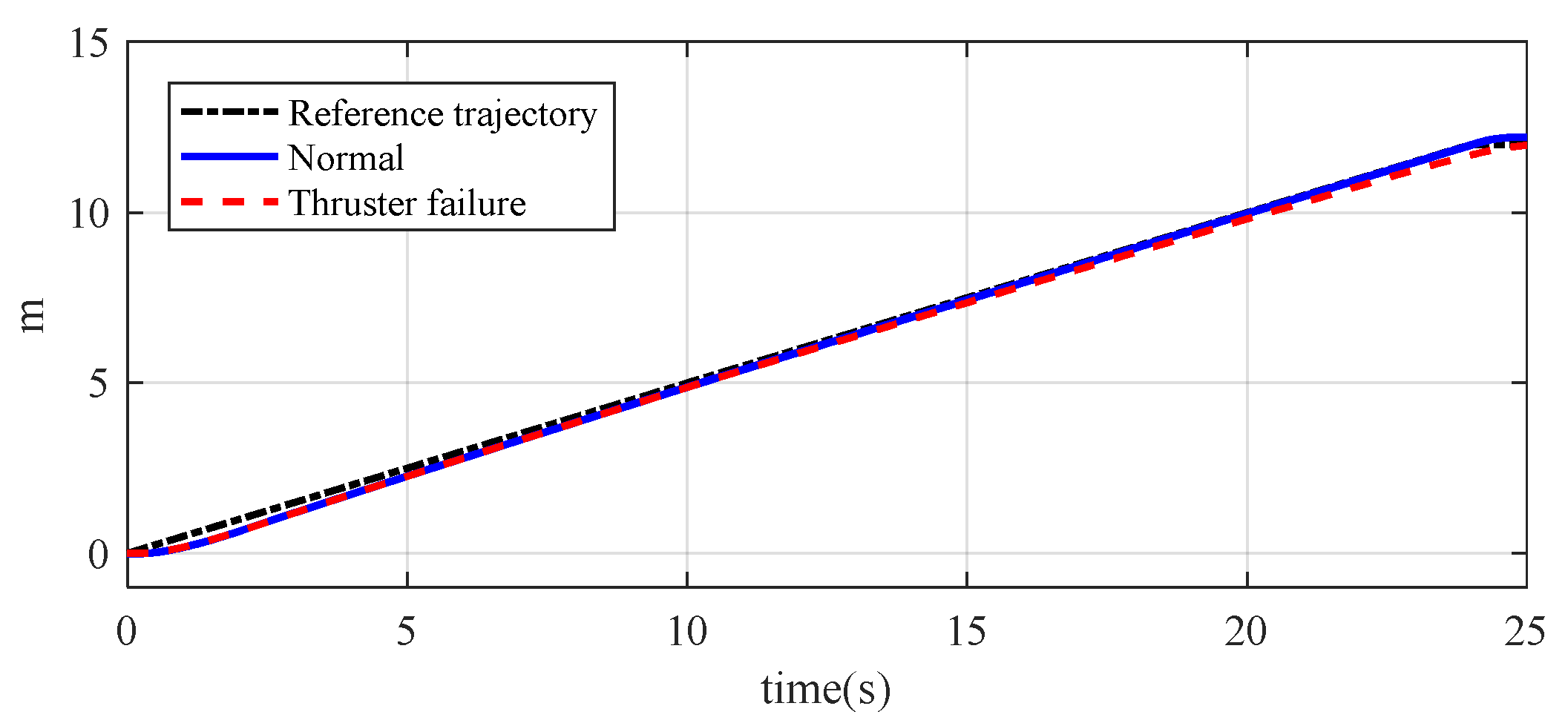
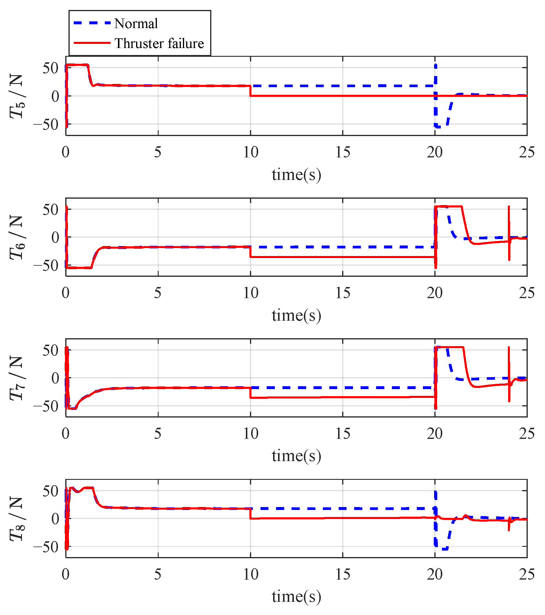
The following analysis examines the situation when one of the vertically arranged thrusters and one of the horizontally arranged thrusters fail. We assume that the 1st thruster and 5th thruster fail after working for 10 s. The underwater vehicle is required to simultaneously perform surge and heave movements, with a speed set to 0.5 m/s, and the trajectory endpoint coordinates set to (10, 0, 12). The vehicle’s trajectory and the variation in thruster output thrust are observed, as shown in
Figure 8,
Figure 9,
Figure 10 and
Figure 11.
In
Figure 8 and
Figure 9, the failure of two thrusters has no impact on the vehicle’s trajectory tracking, and the trajectory almost overlaps with the trajectory when the thrusters are working normally and the reference trajectory.
In
Figure 10 and
Figure 11, we can observe that the output of T1 and T5 decreases to 0 after 10 s due to the failure, and the output of the diagonally arranged 3rd thruster and 8th thruster also significantly decreases. This is to prevent the generation of a thrust difference that could cause overturning torque. The output thrust of the other thrusters increases instantaneously to ensure sufficient output to complete the underwater vehicle’s reference trajectory. After 20 s, the complex variation in thruster thrust is due to the adjustment of the vehicle’s orientation. In conclusion, we can deduce that when one thruster fails vertically and another fails horizontally, it still does not affect the vehicle’s movement, ensuring the fault-tolerance of the underwater vehicle.
4. Thrust Allocation Based on Quadratic Programming
4.1. QP Objective Function Model
The output thrust of each thruster is generally bounded, so the optimal thrust allocation problem can be classified as a quadratic programming problem. The objective of the optimization is to find the solution that minimizes energy consumption. The objective function of the quadratic programming is given in [
31,
32], as shown in the following expression.
The constraint conditions is
where the Hessian matrix,
, is the thruster’s weight distribution matrix. In this study, all the thrusters have the same specifications, and it is assumed that there are no thruster failures during the underwater vehicle movement, so the matrix,
, is the identity matrix.
and
represent the minimum and maximum thrust vectors of the thrusters, respectively.
When considering the thrust saturation issue of the thrusters, the objective of thrust optimization is not only to minimize power but also to minimize the thrust output and the error between the expected control commands. Therefore, the objective function of the thrust allocation optimization is shown in (9).
In the equation, is the weighting coefficient used to adjust the weight of the objective terms; represents the 2-norm.
4.2. Optimization Theorem
The standard form of the QP optimization problem can be expressed as (10):
This quadratic programming problem has a unique solution, , and this solution is the global optimal solution, provided that the following conditions are met.
1. Strict convexity of the objective function.
Since the matrix, , is symmetric and positive definite, the function is strictly convex with respect to .
2. Convexity of the feasible region.
The linear equality constraint, , and the inequality constraints, , define a convex polyhedron feasible region
3. Existence of a unique optimal solution.
Under the conditions of a strictly convex objective function and a non-empty convex feasible region, the optimization problem has exactly one global optimal solution.
4. Strict convexity of the objective function
Since the Slater condition is satisfied, the Karush–Kuhn–Tucker (KKT) conditions are both necessary and sufficient for optimality [
33].
Definition of the Lagrangian function.
The KKT conditions can be expressed as
(4). Complementary slackness
Strict convexity ensures that the solution satisfying the above KKT conditions is the globally unique optimal solution.
In conclusion, the thrust allocation problem in the form of QP has a unique and globally optimal solution, and the theorem is proven.
4.3. Active Set Method
For QP problems, common solution methods include the interior-point method and the active set method. The traditional active set method involves partitioning the constraint set, where all constraints are divided into active and inactive sets during each iteration, which is less efficient in terms of real-time performance. This paper uses the Augmented Lagrangian Method combined with projection operations, avoiding the explicit partitioning of active sets.
Introducing slack variables to handle inequality constraints, the inequality constraint
is transformed into an equality constraint by introducing slack variables
:
The reconstructed optimization problem is as follows:
Define the Lagrange multipliers
(corresponding to the equality constraint
) and
(corresponding to the equality constraint
), and add a quadratic penalty term, resulting in the following equation:
where
are the penalty coefficients.
Use the Alternating Direction Method of Multipliers (ADMM) for iterative computation and avoid explicit active set partitioning through alternating optimization . The specific steps for solving it are as follows:
(1) Update :
Fix
, and solve the unconstrained subproblem
Organize the objective function and take the derivative to obtain the optimal condition
(2) Update :
Fix
, and solving the projection-constrained subproblem
After simplification, it is equivalent to projecting
.
where
represents the projection of
onto the interval
.
(3) Update the Lagrange multiplier:
Integrating the above steps into a unified matrix iteration form. Define the augmented state vector
, then the ADMM iteration can be represented as:
where
is a block matrix that includes
, the projection operation, and
is the constant matrix.
If
, and
, then the sequence
generated by the ADMM iteration converges to the global optimal solution of the original problem. According to the ADMM convergence theory [
34], when the objective function is convex and the constraint set is closed and convex, ADMM will converge in a finite number of steps.
5. Simulation and Analysis
In order to analyze the superiority of quadratic programming, this paper compares the output of quadratic programming with the pseudoinverse of the configuration matrix.
The simulation is conducted in two parts. In the first step, it is assumed that the underwater vehicle moves to a certain position, and its attitude remains unchanged. In the second step, since the underwater vehicle needs to complete a certain task, it needs to flip around the
x-axis. During the flipping process, due to the vehicle ‘s certain stable center of gravity and relatively large weight, it is necessary to overcome the moments generated by gravity and buoyancy. At this point, the four thrusters arranged vertically on top need to output a certain force to accomplish the underwater vehicle‘s flipping task. Therefore, the vehicle ‘s orientation is set to change. The control algorithm used in this paper is fractional-order sliding mode control [
35].
In
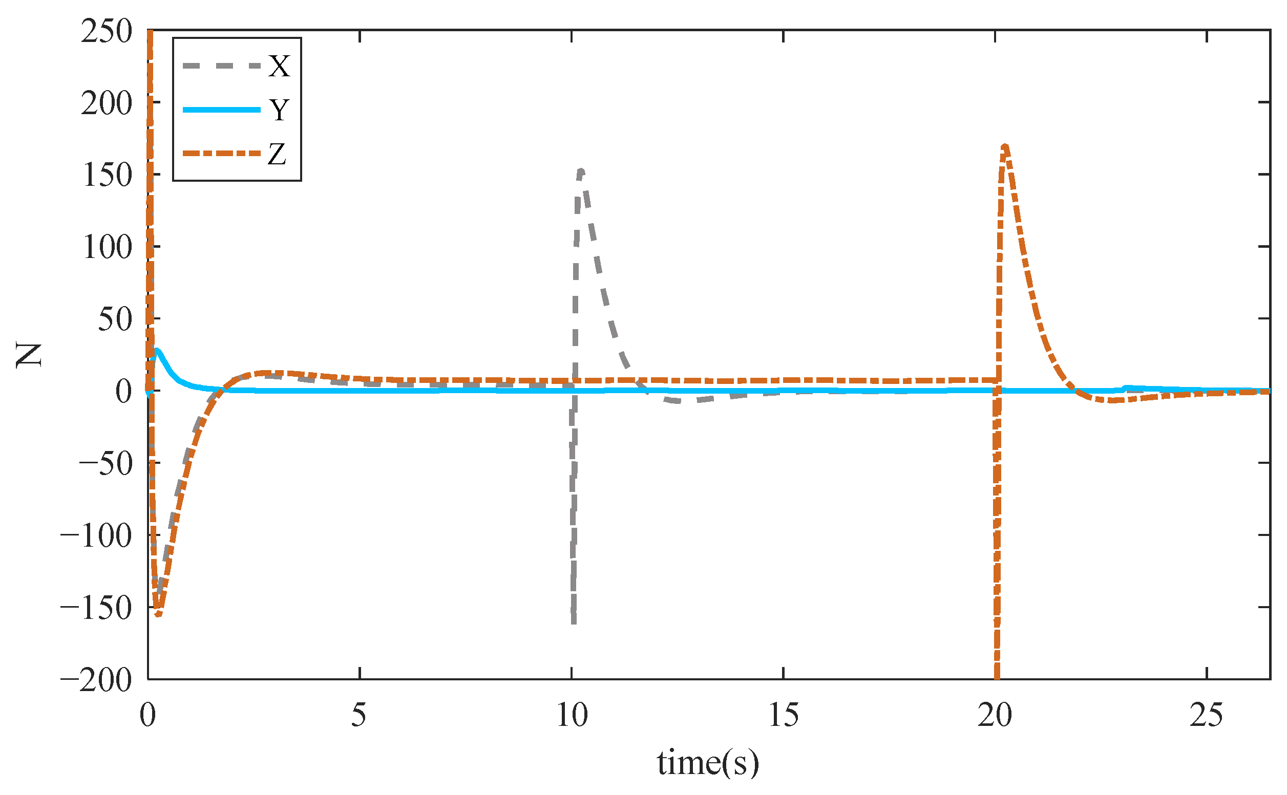
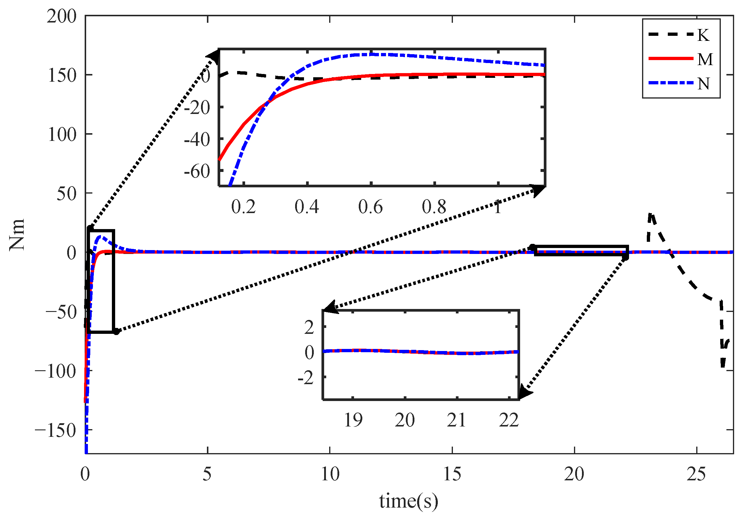
Figure 12 and
Figure 13, the underwater vehicle performs a straight-line trajectory tracking task during the first 20 s, resulting in force outputs along both the
X and
Z. Since no attitude trajectory is specified during this phase, the torques corresponding to the three rotations are nearly zero. It is worth noting that, due to the nonzero initial orientation, the torques exhibit certain outputs during the first 3 s to adjust the orientation to a stable state. Starting from the 23 s, the vehicle is commanded to maintain its spatial position while rotating 1.57 rad around the
x-axis. As a result, the corresponding torque
K increases sharply. Once the orientation reaches the desired angle, the torque gradually decreases and eventually approaches 0.
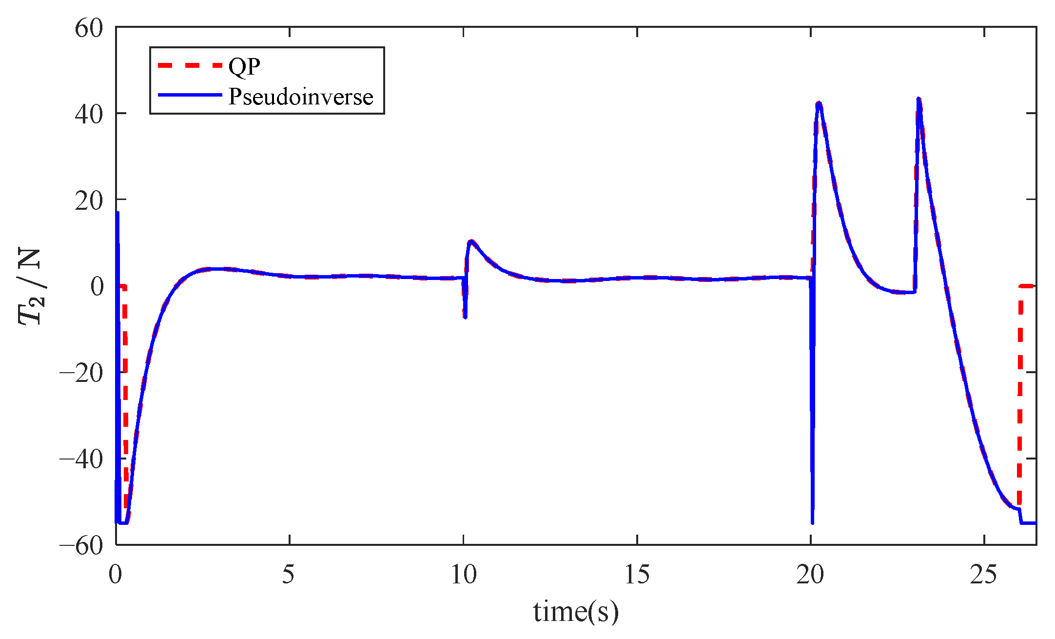
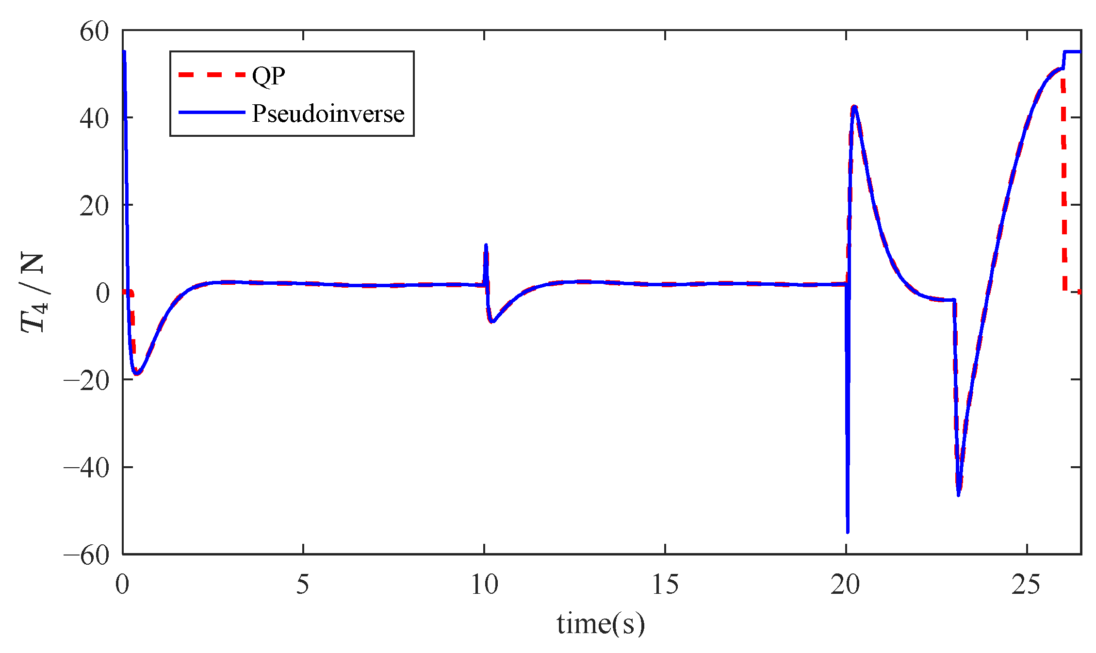
In
Figure 14,
Figure 15,
Figure 16 and
Figure 17, the LS method produces thrust outputs that approach or even reach saturation during several time intervals, indicating that it fails to fully account for physical constraints, thereby posing a risk of thrust saturation. In contrast, the QP method consistently keeps the thrust output strictly within the predefined saturation limits. By incorporating explicit constraints into the optimization process, it effectively avoids saturation and demonstrates strong robustness.
Moreover, the thrust curves generated by the QP method are generally smoother, with significantly less fluctuation compared to the pseudoinverse method. For instance, in the case of the 2nd thruster, the pseudoinverse method results in frequent and severe thrust oscillations, whereas the QP method maintains the thrust variation within ±20N, which helps extend the operational lifespan of the thruster.
Overall, the QP method achieves smooth thrust allocation under strict constraint satisfaction. It not only prevents saturation but also reduces peak energy consumption (e.g., the average thrust amplitude of the 4th thruster is reduced by approximately 30%), making it better suited for high-precision motion control applications.
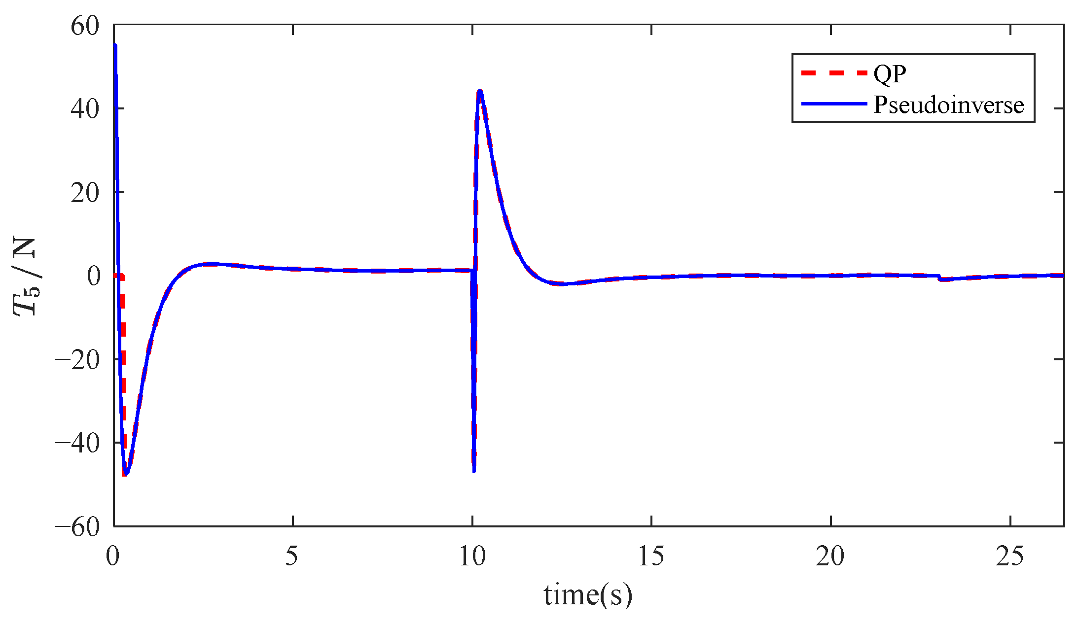
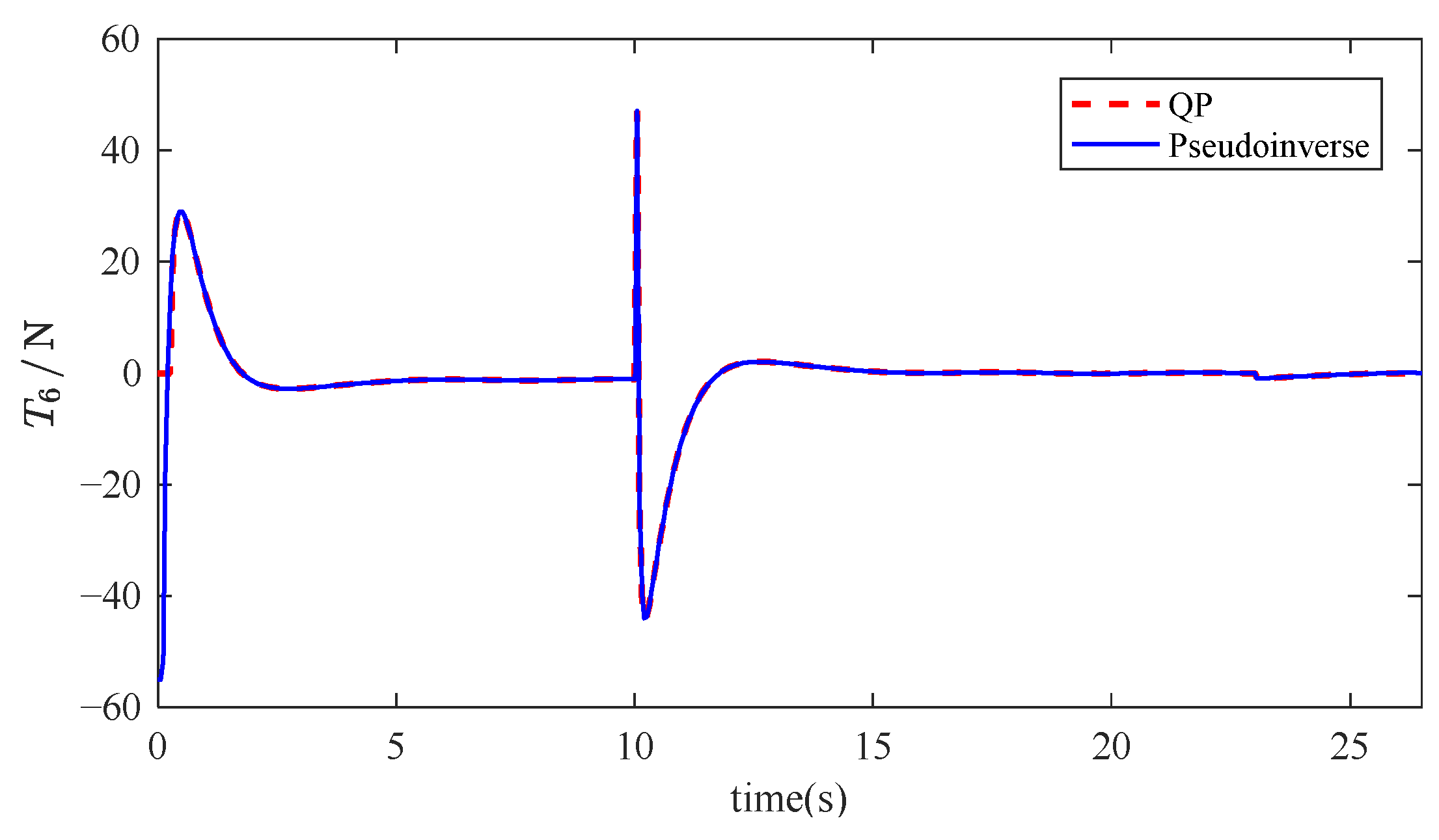
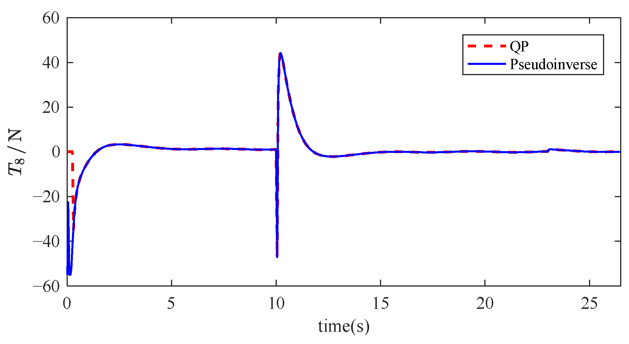
In
Figure 18,
Figure 19,
Figure 20 and
Figure 21, after 15 s, the thrusters output almost no significant thrust. This is because the four horizontally arranged thrusters only control the vehicle’s linear motion along the
x-axis, while the subsequent flipping is achieved by the vertical thrusters. From the graph, it can be observed that the thrust allocation from the least squares planning shows a sudden increase in thrust, which could be damaging to the thrusters’ lifespan. In contrast, the thrust allocation from the QP allocation shows a relatively smooth trend throughout the process.
To analyze the energy consumption of the thrust allocation using QP and LS methods, we perform a comparative analysis using the energy Formula (26).
In
Figure 22 and
Figure 23, the results indicate that the QP method outperforms the LS method in terms of reducing energy dissipation. The LS approach, due to its neglect of physical constraints, causes some thrusters to frequently operate at their maximum output, which increases overall energy consumption. In contrast, the QP method effectively balances the control task among all thrusters, avoiding overload on individual units and significantly reducing energy waste. Furthermore, by leveraging its optimization objective function, the QP method enables cooperative load sharing among thrusters, resulting in a more uniform energy distribution and improved overall system reliability.
Next, we will analyze the energy consumption reduction rate of the QP method through specific numerical comparisons.
In
Table 3, the results shown that the total energy consumption of the QP method is reduced by approximately 23.45% compared to the LS method. Compared with the LS method, QP not only significantly reduces the risk of local thruster overload and extends system lifespan but also provides a more sustainable energy solution for long-term underwater vehicle operations.
6. Discussion
The research on fault-tolerant design and thrust allocation based on QP for an underwater vehicle provides a solid theoretical foundation and technical pathway for enhancing system reliability in complex underwater environments. However, its practical application still faces multidisciplinary challenges and requires continuous optimization and iteration tailored to specific mission scenarios. The following discussion addresses both the effectiveness of the method and the practical challenges involved.
The core of fault-tolerant design lies in mitigating the risk of single-point failures through spatial and functional redundancy. By adopting an 8-thruster statically over-actuated configuration, the system achieves full 6 DOF control, and its effectiveness has been preliminarily validated through simulations and partial experiments. Nevertheless, such redundancy comes at the cost of increased system complexity and financial expenditure. The addition of more thrusters may lead to greater hydrodynamic resistance and increased energy consumption. Thus, it is crucial to balance these trade-offs through lightweight thruster design and efficient energy management strategies.
The QP-based thrust allocation method is effective in handling constrained optimization problems, but its computational complexity imposes high demands on the processing capabilities of embedded control systems. In highly dynamic underwater environments, if the optimization computation delay exceeds 10ms, it may result in untimely control responses or even system instability. This issue becomes particularly critical when multiple thrusters fail consecutively, potentially causing the remaining thrusters to reach output saturation and fail to meet the control requirements. In such cases, traditional QP algorithms may yield no feasible solution.
In conclusion, the fault-tolerant design and QP-based thrust allocation method offer fundamental theoretical tools for underwater vehicles to cope with failures and external disturbances. However, real-world deployment still requires overcoming key challenges related to real-time performance, robustness, and environmental adaptability. Future research should focus on the integration of intelligent algorithms, innovations in multi-vehicle cooperative control, and the development of novel, high-efficiency hardware. Furthermore, long-term validation in real marine environments should be strengthened to advance underwater vehicles from laboratory prototypes to large-scale, practical engineering applications.
7. Conclusions
This paper addresses the key challenges in thruster configuration and fault-tolerant thrust allocation for an underwater vehicle by proposing an 8-thruster spatial vector layout and a thrust allocation strategy based on QP. Fault-tolerance analysis shows that the proposed redundant thruster configuration can maintain basic motion control capabilities even in the event of partial thruster failures, demonstrating strong fault adaptability. The proposed QP-based thrust allocation method significantly improves energy efficiency while strictly satisfying thruster saturation constraints and real-time computational requirements. This study not only provides theoretical support for the design of redundant thruster systems but also offers a practical solution for achieving high-precision motion control in complex and fault-prone underwater environments. It lays a solid foundation for the reliable deployment of autonomous underwater vehicles in tasks such as deep-sea exploration and subsea infrastructure inspection.
Despite its strengths, the QP-based thrust allocation approach has several limitations. The current formulation assumes perfect knowledge of the thruster configuration matrix and ignores hydrodynamic disturbances. In reality, modeling and estimation errors can erode both allocation optimality and fault-tolerance margins. Moreover, enforcing hard saturation constraints can lead to premature thruster derating, shrinking the vehicle’s achievable workspace. Future work will, therefore, focus on embedding robust and adaptive elements into the QP framework, such as integrating disturbance observers and employing chance constraints to explicitly handle uncertainty, expanding the library of fault models, and validating the method’s effectiveness through hardware in the loop tests and fully autonomous sea trials.


