1. Introduction
The endeavor to construct quantum computers that surpass the capabilities of classical computers poses a significant challenge in our era. It is important to acknowledge that this goal has not yet been realized. However, substantial progress is evident, as illustrated by IBM’s advancements with the 127-qubit Eagle [
1], the 433-qubit Osprey [
2], the 1121-qubit Condor [
3], and the latest and most powerful R2 Heron [
4]. These developments indicate a swift movement towards the practical application of quantum technology. All these suggest that quantum technology has reached a level of maturity that warrants careful consideration in the development and implementation of algorithms targeting difficult problems.
The imperative to enhance the scale of quantum computers represents the most significant obstacle to their potential application in industrial-scale problems. It has become evident that advancing quantum computers beyond the Noisy Intermediate-Scale Quantum (NISQ) level will necessitate scientific breakthroughs and the resolution of various technological hurdles. In our assessment, the most promising strategy to address the scaling dilemma currently lies in the advancement of distributed quantum computing systems. In the realm of classical computing, the concept of interlinking smaller processors to distribute computational tasks has emerged as a solution to scaling difficulties. This principle is believed to be equally relevant to quantum computing, where the scaling challenge encourages the exploration of connecting smaller quantum computers. A distributed quantum computing system would comprise a network of quantum nodes, each possessing a specific number of qubits for processing and the capability to transmit both classical and quantum information. Nevertheless, the inherent differences between quantum and classical computing introduce unique challenges, not present in classical networks, in the design of networked quantum computers. Fortunately, recently there have been significant technological advancements in hardware [
5,
6] and design concepts [
7,
8]. In fact, very recently, researchers demonstrated distributed quantum computing by employing a photonic network interface to effectively connect two distinct quantum processors, thus creating a unified and fully integrated quantum computer [
9,
10]. It is our firm belief that we are entering the era of distributed quantum computing.
In this work, we introduce a new quantum algorithm that classifies classes of Boolean functions that are characterized by specific patterns that exhibit imbalance. The fundamental characteristic of these imbalanced Boolean functions is that the proportion of elements in their domain that take the value 0 is not equal to the proportion of elements that take the value 1. We refer to this algorithm as the Boolean Function Pattern Quantum Classifier, or BFPQC for short.
Quantum classification of Boolean functions is important because it bridges theoretical quantum advantages, such as query complexity reductions, with practical applications in cryptography, quantum machine learning, and optimization. In cryptography, Boolean functions in block ciphers must satisfy properties like nonlinearity, balancedness, or correlation immunity. Quantum classification can accelerate the evaluation or optimization of such functions, aiding in cryptanalysis or designing secure systems. Quantum algorithms like the Deutsch–Jozsa algorithm demonstrate exponential speedup for certain Boolean function properties (e.g., determining if a function is constant or balanced). While this is a toy problem, it hints at quantum advantages for classification tasks involving Boolean functions with specific structures. Quantum kernel methods, such as those using Quantum Support Vector Machines (QSVMs), map Boolean inputs into high-dimensional quantum feature spaces via quantum circuits. This may reveal patterns in Boolean functions that are intractable classically, especially for functions with complex dependencies. In machine learning, many real-world datasets involve binary or categorical features. Quantum classification of Boolean functions can enhance classical machine learning models by exploiting quantum parallelism to process high-dimensional binary inputs more efficiently. Variational Quantum Classifiers use parameterized quantum circuits to learn Boolean functions. For example, a VQC can be trained to classify inputs based on a target Boolean function (e.g., parity, majority, or threshold functions), potentially requiring fewer parameters or shallower circuits than classical neural networks for certain tasks. While current hardware limitations (e.g., noise) restrict large-scale deployment, near-term systems excel in niche problems with structured data or specific function properties. As fault-tolerant quantum computers emerge, the ability to classify complex Boolean functions efficiently could revolutionize computational tasks.
We have drawn inspiration mainly from the many sophisticated works studying various extensions of the Deutsch–Jozsa algorithm. Already in [
11], the authors examined a multidimensional version of the Deutsch–Jozsa problem. This was further expanded in [
12] by considering evenly distributed and evenly balanced functions. Subsequently, in [
13], the Deutsch–Jozsa algorithm was extended for balanced functions in finite Abelian subgroups. Another generalization appeared in [
14]. Later, the researchers in [
15] generalized the Deutsch–Jozsa problem and gave an optimal algorithm. A more recent clever generalization of the Deutsch–Jozsa algorithm can be found in [
16]. Useful applications of the Deutsch–Jozsa algorithm were also obtained in [
17,
18]. Two particularly interesting works towards establishing a distributed version of the Deutsch–Jozsa algorithm were [
19,
20]. In a related development, the authors in [
21] extended Deutsch’s algorithm for binary Boolean functions.
Important general results for query complexity in the oracle model were presented in [
22], where a sophisticated upper bound for the number of Boolean functions that can be distinguished with
k quantum queries was derived, and in [
23], where two methods for proving lower bounds on quantum query complexity were studied. A noteworthy result was obtained in [
24], where the problem of quantum learning from a noisy quantum example oracle was investigated, and it was shown that the class of parity functions can be learned in logarithmic time from corrupted quantum queries. We should also mention that oracular algorithms geared towards computing Boolean functions or achieving classification are often encountered in the literature on quantum learning and quantum machine learning. In [
25], it was shown that the class of polynomial-size Disjunctive Normal Form expressions is efficiently learnable with respect to the uniform distribution by a quantum algorithm using a quantum example oracle. The authors in [
26,
27] demonstrated an important correlation between classical and quantum learning for both the models of exact learning and probably approximately correct learning from random examples. In [
28], the authors introduce an advanced and sophisticated general technique for quantum concept learning. In a related work [
29], the number of quantum queries required to identify an unknown multilinear polynomial of degree
d in
n variables over a finite field was established. The authors in [
30] compared a quantum and a classical machine designed for learning Boolean functions in order to address how a quantum system improves the machine learning behavior, and concluded that the quantum machine has a wider acceptable region, induced by quantum superposition. The researchers in [
31] presented quantum algorithms for performing nearest-neighbor classification and
k-means clustering that promise significant reductions in their query complexity relative to their classical counterparts. Quantum oracles were shown to reduce the time required to train a deep restricted Boltzmann machine and provide a richer and more comprehensive framework for deep learning than classical computing in [
32].
We present our algorithm in the form of game, called the Classification Game, that features the familiar characters of Alice and Bob. It is anticipated that the entertaining aspect of games will facilitate a better understanding of the technical concepts involved. Since their introduction in 1999 [
33,
34], quantum games have gained considerable popularity, as quantum strategies often outperform classical ones [
35,
36]. A notable illustration of this is the well-known Prisoners’ Dilemma [
34], which serves as a prime example and is applicable to various other abstract quantum games [
37]. Although quantum games are fun, they can be used to solve critical problems like Quantum Key Distribution, Quantum Secret Sharing, and Quantum Private Comparison (see [
38,
39]). It is worth noting that many classical systems can be turned into quantum versions, including political frameworks, as demonstrated in recent studies [
40].
Contribution. In this paragraph we present what we believe to be the main novelties introduced in this work.
Numerous sophisticated studies have been published in the literature that employ quantum oracles to classify Boolean functions, such as those that expand upon the Deutsch–Jozsa algorithm. The vast majority of them explore balanced Boolean functions. However, as far as we are aware, there has been no previous research dedicated to imbalanced Boolean functions, which are characterized by an unequal number of elements in their domain that yield the values 0 and 1. This article introduces a novel quantum algorithm designed to classify a specific hierarchy of imbalanced Boolean function classes. For each positive integer, n, this hierarchy includes a class of Boolean functions, which are defined according to their behavioral characteristics. A defining feature of all functions within the same class is their shared imbalance ratio.
Our algorithm achieves classification in a straightforward manner, as the final measurement determines the unknown function with a probability of
. A thorough complexity analysis of our algorithm is given in
Section 5.1. This analysis proves that our algorithm is an optimal oracular algorithm, capable of conclusively classifying all Boolean functions belonging to the designating hierarchy with a probability of
using just a single query to the oracle. At the same time, we show that our algorithm is superior to any deterministic classical algorithm for the same task.
Of equal importance is the detailed explanation of the methodology followed in the development of this algorithm that we provide in
Section 4. This is done with the expectation that it will prove both general and beneficial, as it can be readily adapted and expanded to tackle other classes of imbalanced Boolean functions that display varying behavioral patterns. The intuition of our methodology can be distilled in the phrase “from behavior to pattern vectors and then to unitary classifiers”. By appropriately modifying Definition 9 to include different pattern bases, one may construct unitary classifiers for these patterns, leading to new classification algorithms.
Organization
This article is structured in the following way.
Section 1 introduces the topic and includes references to the relevant literature.
Section 2 offers a brief overview of key concepts, which serves as a basis for grasping the technical details.
Section 3 contains a comprehensive exposition to our algorithm, including a detailed small-scale example to build intuition. The general form of the algorithm is formally presented in
Section 4. Finally, the paper wraps up with a summary and a discussion of the algorithm’s nuances in
Section 5.
2. Notation and Terminology
2.1. Boolean Functions and Oracles
Let us first fix the notation and terminology we shall be using in the rest of this paper.
is the binary set .
A bit vector, , of length n is a sequence of n bits: . Two special bit vectors are the zero and the one bit vectors, denoted by and , in which all the bits are zero and one, respectively: and .
To make clear, when we refer to the bit vector , we write in boldface. Often, it is convenient to view as the binary representation of the integer b.
Each bit vector, , can also be viewed as the binary representation of one of the basis kets that form the computational basis of the -dimensional Hilbert space.
Definition 1 (Boolean function). A Boolean function, f, is a function from to , .
Oracles are an important concept in quantum computing and play a crucial role in many quantum algorithms. An oracle is a black box that encodes a specific function or information into a quantum circuit, allowing quantum algorithms to solve problems more efficiently than classical algorithms in certain cases. It is used to evaluate the function or check a condition without revealing the internal details of how the function works. In quantum algorithms, oracles are often used to mark solutions to a problem or to provide information about a function’s behavior. For the purposes of our work, the following definition suffices.
Definition 2 (Oracle and unitary transform). An oracle is a black box implementing a Boolean function, f. The idea here is that, being a black box function, we know nothing about its inner workings apart from the fact that it works correctly. Thus, it can be used for the construction of a unitary transform, , that captures the behavior of f.
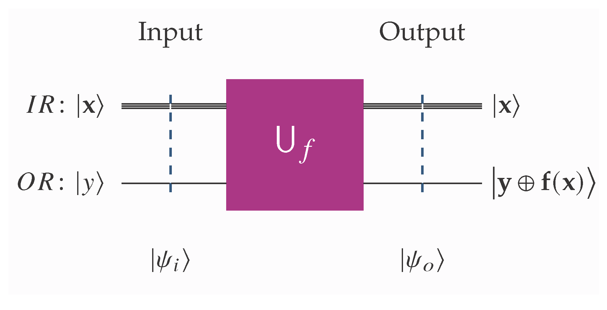
Henceforth, we shall assume that the corresponding unitary transform, , implements the standard schema In the literature, this type of oracle is sometimes referred to as a Deutsch–Jozsa oracle. We note in passing that there also other variations of oracles, such as the Grover oracle, which is typically used to mark solutions to a problem. In this work, every oracle and unitary transform is assumed to satisfy (
1) and is used to deduce a function from its behavior. The standard measure of complexity in oracular algorithms is the query complexity, i.e., the number of queries to the oracle used by the algorithm.
For completeness, we recall the states |+〉 and |−〉, which are defined as
To obtain any useful information from schema (
1), we set |
y〉 equal to |−〉, in which case (
1) takes the following familiar form:
Figure 1 and
Figure 2 give a visual outline of the unitary transforms,
, that implement schemata (
1) and (
4), respectively. In all the quantum circuits used in this work, including those depicted in
Figure 1 and
Figure 2, the following conventions are used.
We mention that in the literature it is very common to use the word “promise” when referring to a particular property of the Boolean function f, meaning that we are guaranteed, or, if you prefer, we are certain with a probability of that f satisfies the property in question. A prominent such example comes from the Deutsch–Jozsa algorithm, where we are given the promise that f is either constant, or balanced.
Extending the operation of addition modulo 2 to bit vectors is a natural and fruitful generalization.
Definition 3 (Bitwise addition modulo 2).
Given two bit vectors, , with and , we define their bitwise sum modulo 2, denoted by , as Following the standard approach, we use the same symbol, ⊕, to denote the operation of addition modulo 2 two between bits, and the bitwise sum modulo 2 between two bit vectors because the context always makes clear the intended operation.
2.2. A Brief Recap of the Deutsch–Jozsa Algorithm
In this subsection, we recall a few standard operations between bit vectors that will facilitate the forthcoming exposition, and give a brief reminder of the Deutsch–Jozsa algorithm.
Definition 4 (Inner product modulo 2).
The inner product modulo 2
is a function from to that takes as inputs two bit vectors, , and returns their inner product denoted by . If and , then is defined aswhere := stands for “is defined as”, and ⊕ is addition modulo 2. The fundamental relation that expresses the
n-fold Hadamard transform of an arbitrary basis ket |
〉 uses the inner product modulo 2. Its proof can be found in most standard textbooks, e.g., [
42,
43].
The Deutsch–Jozsa algorithm is a famous quantum algorithm that solves a specific problem faster than any classical algorithm. It determines whether the given Boolean function is constant (produces the same output for all inputs) or balanced (outputs 0 for half the inputs and 1 for the other half) with a single function evaluation, compared with up to evaluations classically.
The algorithm takes as input an oracle for the unknown function,
f. The oracle is of the Deutsch–Jozsa variation and the function
f is promised to be either constant or balanced. The goal is to establish whether
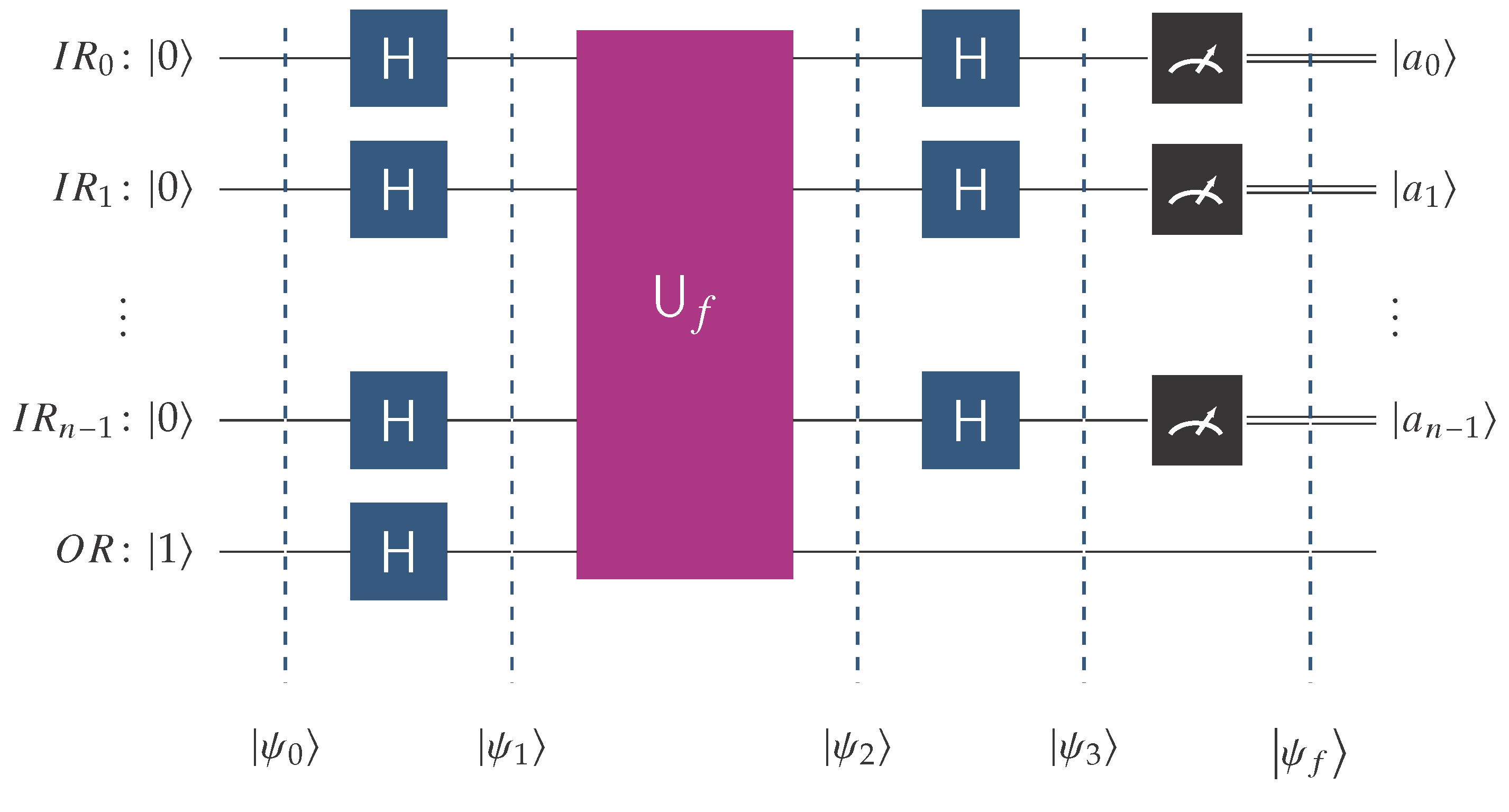
f is constant or balanced with a single oracle query. The abstract quantum circuit in
Figure 3 visualizes the implementation of the Deutsch–Jozsa algorithm.
In the above
Figure 3, the following notation is employed.
is the quantum input register that contains n qubits and starts its operation at state .
is the single-qubit output register initialized to state |1〉.
H is the Hadamard transform.
is the unitary transform corresponding to the oracle for the unknown function, f. The latter is promised to be constant or balanced.
Referring to
Figure 3 and recalling that ordering the qubits adheres to the Qiskit [
41] convention, we may express the initial state,
, as shown below
Applying Hadamard gates to all qubits leads to the next state,
, which, by taking into into account (
7) for
=
and (
3), can be written as
The oracle’s action implementing schema (
4) evolves the state to
Intuitively, this means that the oracle has encoded the output values of the Boolean function
f, into the relative phase
of state
. It is at this point exactly that we encounter the
phase kickback phenomenon. Phase kickback is a fundamental trait of many quantum algorithms because an operation on the ancilla qubit induces a phase shift on the control qubits. In our case, the control qubits are the
n qubits of the quantum input register,
, and the ancilla qubit is the single-qubit output register,
. To successfully employ this technique, it is necessary for the ancilla qubit to be in state
=
=|−〉 (recall Equation (
3)). Using phase kickback is crucial because the oracle instead of writing does
explicitly to a qubit, and encodes it as a relative phase
. This approach not only forfeits the need for additional storage qubits, but also allows the desired interference to happen cleanly. An obvious way to generate |−〉 is to initialize the ancilla qubit to state |1〉 and, subsequently, apply the Hadamard transform,
H, as depicted in the quantum circuit of
Figure 3. Modern-day quantum computers allow for the immediate initialization of qubits to states other than |0〉 and |1〉, such as |−〉. We have taken advantage of this capability by directly initializing to |−〉 the output register,
, playing the role of the ancilla qubit, in all of the quantum classification circuits shown in the rest of this paper. The classification algorithm we present in this work also relies on the Deutsch–Jozsa oracle type and utilizes the phase kickback technique to encode the behavioral pattern of the unknown function,
f, into the relative state of the quantum input register,
.
Subsequently, by applying Hadamard gates to the
n qubits of the quantum input register,
, we drive the system into the
described below
Focusing on the amplitude of the basis state
=
within state
, we see that it is given by the next equation
which enables us to distinguish between the following two antidiametrical cases.
- (DJ1)
If
f is constant, then (
7) reduces to
.
- (DJ2)
If
f is balanced, then (
7) reduces to
.
Thus, if we measure we are absolutely certain that f is constant, whereas any other outcome means that f is balanced.
From a historical perspective, this algorithm was one of the first to show a clear quantum advantage, paving the way for more complex quantum algorithms like Shor’s and Grover’s. Its speedup is evident because the quantum algorithm uses 1 query vs. up to classically. Furthermore, it demonstrates quantum parallelism by evaluating f on all inputs simultaneously, and interference by amplifying desired outcomes.
3. The Basic Concepts Behind the BFPQC Algorithm
In this paper, we introduce a new quantum algorithm that differentiates and classifies a class of Boolean function that is characterized by a specific collection of patterns demonstrating imbalance. In view of its intended purpose, we call this algorithm the Boolean Function Pattern Quantum Classifier, or BFPQC for short. The current section gives the definitions regarding the main concepts, and presents a toy scale example illustrating its operation.
By giving rise to different elements of the computational basis with a probability of . Our algorithm is an oracular algorithm because it relies on a oracle to achieve the classification. Its efficiency is demonstrated by the fact that it is optimal because it requires just one single query to complete its task.
Here we solve what is commonly referred to in the quantum literature as a promise problem, i.e., a problem where the input is promised to belong to a specific set. Promise algorithms are not required to work correctly on any input that does not satisfy the promise. Many quantum algorithms are designed to solve promise problems. For example, in the Deutsch–Jozsa algorithm, the promise is that the function is either constant or balanced. The Deutsch–Jozsa algorithm is designed to distinguish between these two cases efficiently, but it does not need to handle functions that are neither constant nor balanced. The same applies to our case: the BFPQC algorithm can correctly handle any function that belongs to a rigorously defined hierarchy, but it will not output the correct answer if this is not the case.
Our plan of action consists of the following successive steps.
- (S1)
We focus on imbalanced Boolean functions, i.e., those with the property that the number of elements in their domain that take the value 0 is not equal to the number of elements that take the value 1.
- (S2)
We employ the concept of pattern vectors to capture the behavior of imbalanced Boolean functions. For each positive integer , we define a set of pattern vectors that all have an equal imbalance ratio, which is always .
- (S3)
Identifying an appropriate set of pattern vectors enables the construction of the corresponding unitary transform that accomplishes the classification.
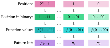
Definition 5 (Pattern vector). Given the Boolean function , , we define the concept of the unique pattern vector that encodes the behavior of f.
The pattern vector =… of f is the element of , such that , where is the binary bit vector representing integer i, . In other words, the pattern vector, , lists the binary values of as ranges over . To enhance comprehension, we visualize the details below.![Mathematics 13 01750 i001 Mathematics 13 01750 i001]()
Given the pattern vector =… of f, its negation, denoted by , is the pattern vector …, which corresponds to the function .
It is clear by the preceding Definition 5 that there is a one-to-one correspondence between Boolean functions and patterns vectors. We could say that a Boolean function and its pattern vector are the two sides of the same coin. Therefore, just as knowing the behavior of a Boolean function enables the construction of its pattern vector, conversely, the pattern vector contains all the information necessary to reconstruct the Boolean function. This duality is emphasized by
Figure 4.
Definition 6 (Orthogonal pattern vectors). Consider the distinct pattern vectors and , corresponding to the Boolean functions . and are orthogonal if contains 0 s and 1 s.
Definition 7 (Imbalance ratio).
Given a pattern vector, , of length , let and denote the number of 0s and 1s appearing in . The imbalance ratio
of is defined as If is the pattern vector of f, we shall also say that ρ is the imbalance ratio of f. In the same spirit, if P and F are a collection of pattern vectors and a collection of Boolean functions with the common imbalance ratio ρ, respectively, we will speak of ρ being the imbalance ratio of P and F. As we pointed out previously, we visualize the execution of the BFPQC algorithm as the evolution of the Classification Game played between our prolific stars Alice and Bob, according to the following rules.
- (G1)
Bob is free to choose any Boolean function, provided that it belongs to the promised class of functions.
- (G2)
Bob wins the game if Alice fails to recognize the chosen function with one try. Otherwise, Alice is the winner.
- (G3)
In terms of implementing the game as a quantum circuit, Bob chooses the hidden oracle, while Alice furnishes the classifier.
Before we proceed to introduce more technical machinery, we give a toy scale example to build intuition.
Example 1 (A toy scale example).
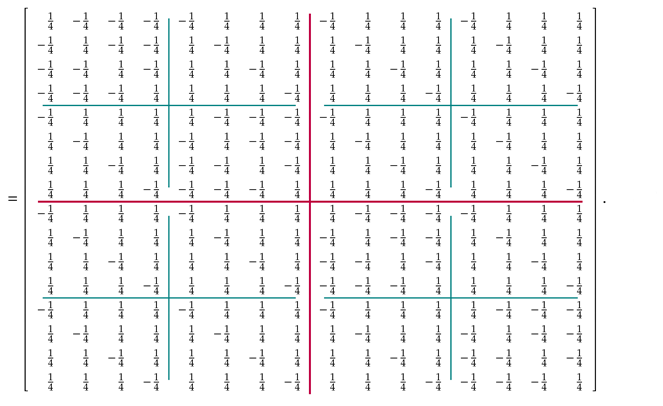
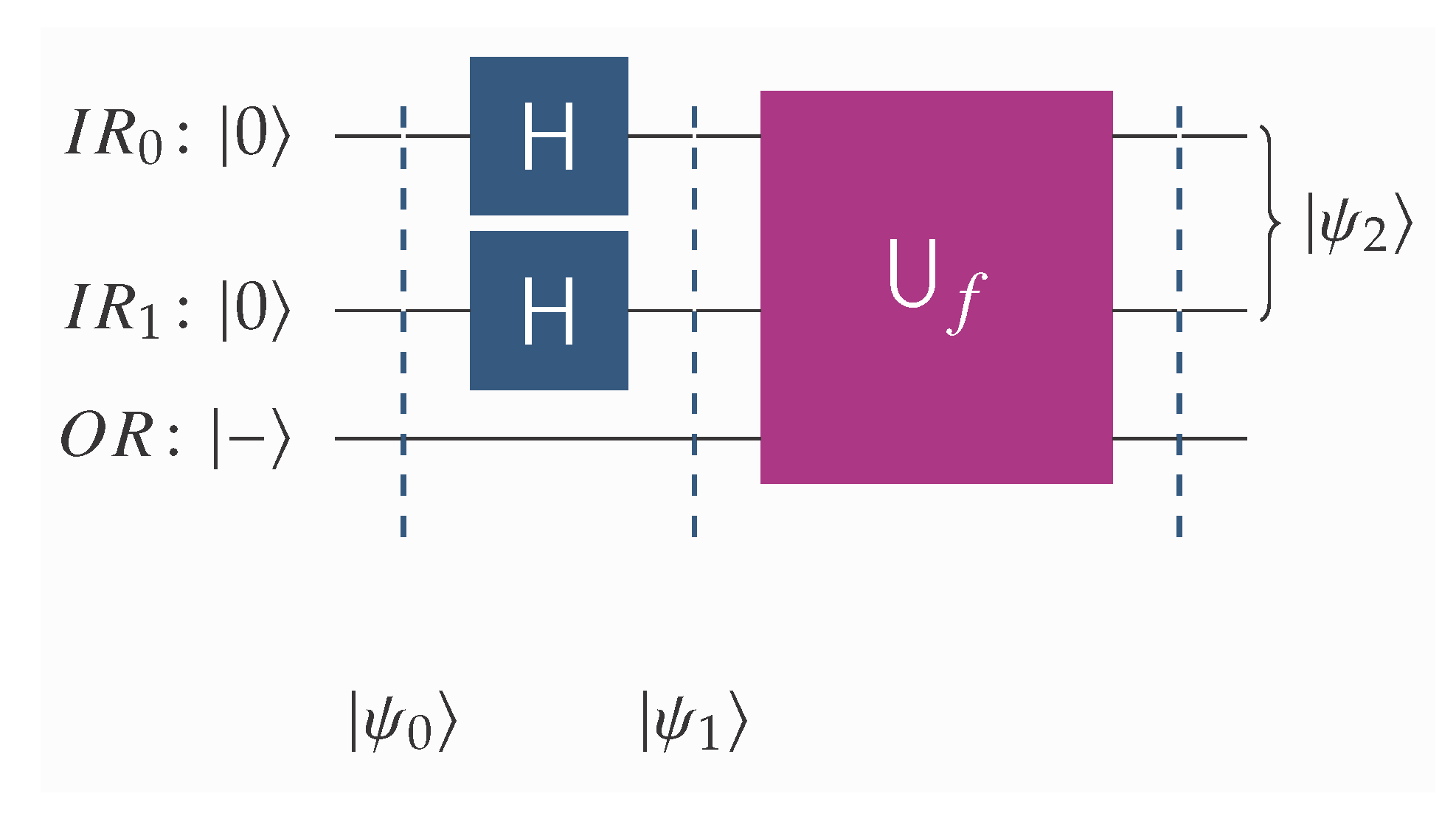
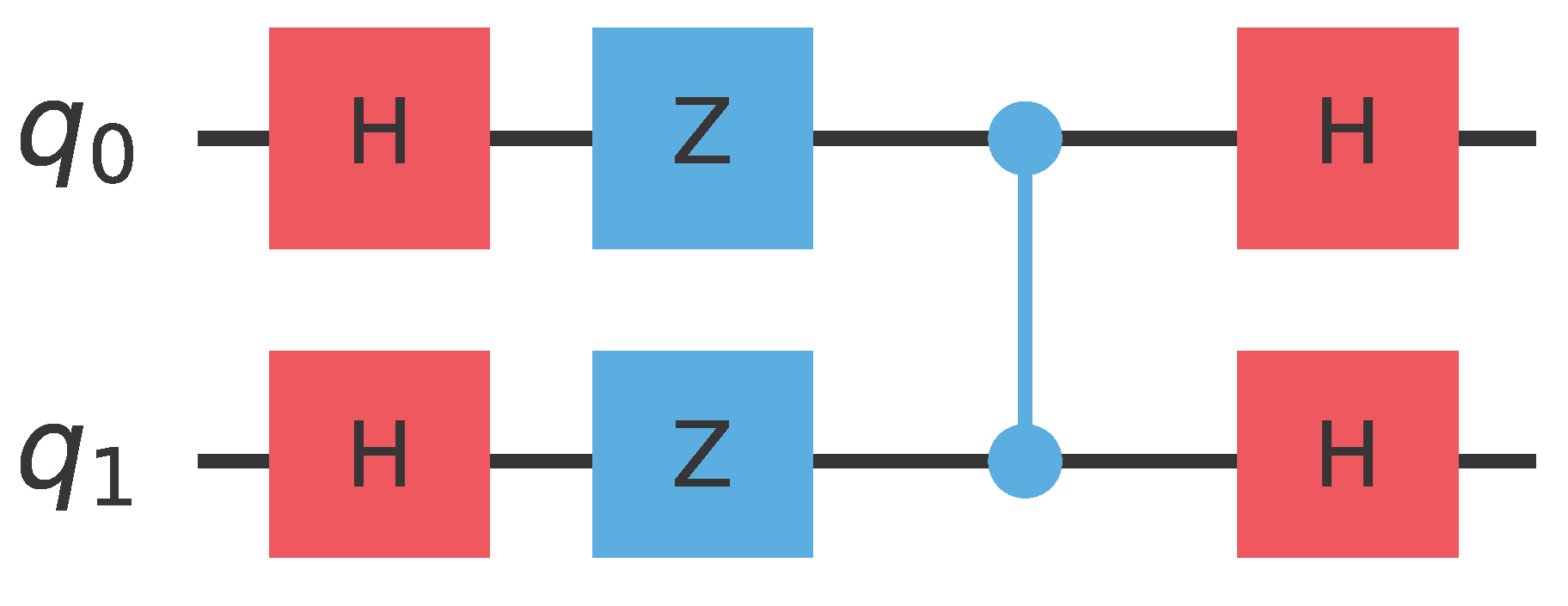
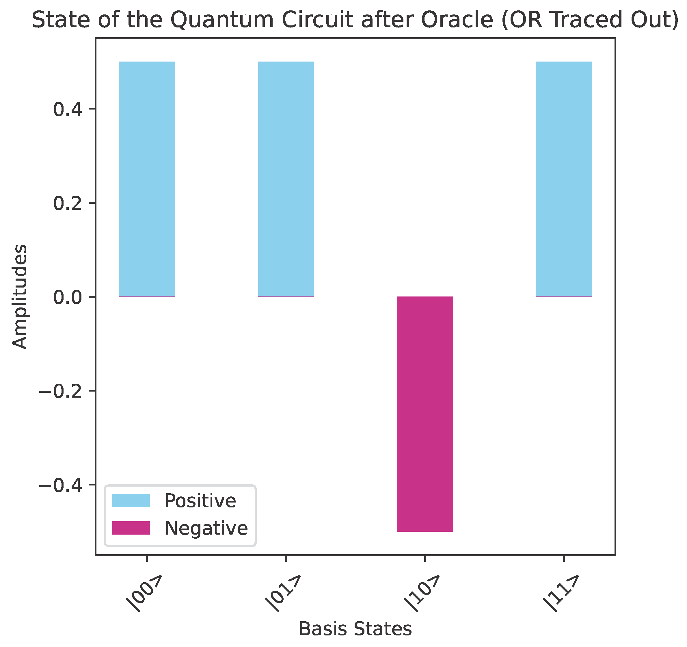
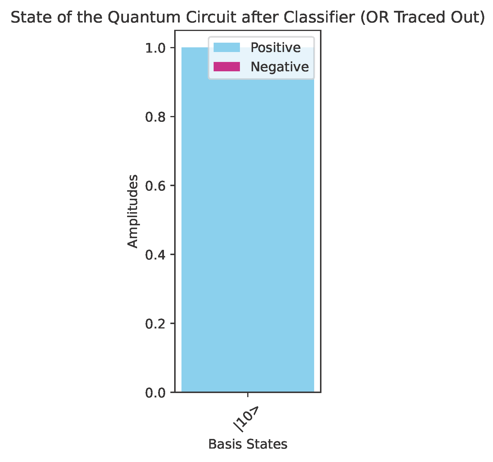
Let us consider the following two families of Boolean functions defined on .Their truth values and pattern vectors are given in Table 1 and Table 2 below. The four functions , and exhibit a common pattern: for precisely one element, , their value is 1, while for the remaining three elements their value is 0. Symmetrically, the four functions , and exhibit an analogous motif, i.e., for precisely one element, , their value is 0, while for the remaining three elements their value is 1. Obviously, this is because , . The imbalance ratio, ρ, for both families is the same, namely . The four pattern vectors shown in Table 1 are pairwise orthogonal and constitute the set . An important observation at this point is that, although and are logically different, within our quantum context and are indistinguishable because they lead to the same state. For future reference, we gather the Boolean functions into one set, which we call . Given any function in , it is easy to construct the corresponding oracle using standard quantum gates. Accordingly, it is possible to distinguish among the four Boolean functions . Hence, given the promise that the unknown function, f, is one of the above four Boolean functions, and having the corresponding oracle, the aim of the Classification Game is to construct a quantum circuit that allows Alice to win with absolute certainty, i.e., with a probability of . The initial segment of such a circuit is shown in Figure 5. is the oracle of the hidden function, chosen by Bob. After the application of the unitary transform, , the state of the quantum input register, , will be . As is the norm in such cases, we ignore from now on the output register, , since its state remains |−〉. It is quite straightforward to verify the precise dependency of on each of the functions in , which is shown in Table 3. The important observation here is that each of the four leads to a different , which means that we can distinguish and classify them. However, as expected, state is the same for each pair of functions and , which means that they are indistinguishable. Alice now employs a unitary transform that can differentiate among the four Boolean functions , and , such as . The matrix representation of is given by Equation (13). It is easy to verify that the action of on the four possible states, , leads to the states shown in Table 4, which are precisely the basis kets of the computational basis . It is straightforward to build using standard quantum gates readily available in contemporary quantum computers. Below we show in Figure 6 such a construction that requires only Hadamard, Z, and controlled-Z gates: Regarding the schematic of Figure 5, we note the following. is the least significant qubit and is the most significant qubit of the quantum input register, , that contains 2 qubits.
is the single-qubit output register that is initialized to state |−〉.
H is the Hadamard transform.
is the unitary transform that is based on the oracle for the unknown function, f, and satisfies relation (4).
Therefore, the quantum algorithm that classifies each Boolean function contained in can be visualized by the quantum circuit depicted in Figure 7. Alice surely wins because the action of the classifier results in the final state of the system being one of the four basis kets of the computational basis . Specifically, if the oracle encodes , the final state will be , where is the binary representation of the index i, . Therefore, upon the final measurement, Alice will surmise the correct hidden function with a probability of . An actual implementation of the abstract quantum circuit of Figure 7 in Qiskit [41] using the oracle for the function is depicted in Figure 8. Let us clarify that in all the figures in this paper the qubit numbering follows the “little-endian” convention, where is the rightmost qubit is the least significant qubit (LSQ), and the leftmost qubit is the most significant qubit (MSQ). Figure 9 shows the state of the quantum circuit of Figure 8 after the oracle but before the action of . The main property of is its ability to distinguish and classify the superpositions of the basis kets of the computational basis in which exactly three kets appear with same sign and the fourth ket appears with the opposite sign. Thus, the state of the quantum circuit after the action of will be |10〉, as depicted in Figure 10. We observe that the four different Boolean functions give rise to four different orthonormal states, . Thus, the task of differentiating among the four Boolean functions can be reduced to the task of using a unitary transform that maps the four orthonormal states to the computational basis .
4. The General Form of the BFPQC Algorithm
In this section we present the general form of the BFPQC algorithm. For this purpose, we extend the definitions given in the previous section.
Definition 8 (Pattern basis). A pattern basis of rank , is a collection of pairwise orthogonal pattern vectors of length , denoted by .
The initial pattern basis,
, is the set consisting of the following four pairwise orthogonal pattern vectors:
Starting from , we may define an infinite hierarchy of pattern bases. The details are explained below.
Definition 9 (Pattern hierarchy). We recursively define a hierarchy of pattern bases , as follows.
- (PH0)
If , the corresponding pattern basis is the set , as defined by (15). - (PH1)
Let contain the pattern vectors ; then, the pattern basis consists of the pattern vectors with the following syntax structure:
An easy conclusion of the above definition is that every
,
, contains
pairwise orthogonal pattern vectors. Henceforth, we shall assume that the
pattern vectors contained in
are enumerated as
according to the order prescribed by Formula (
16).
Example 2 (Pattern basis
).
To facilitate the understanding of Definition 9, we list in Table 5 to show how it is derived from . Definition 10 (Functions from patterns). To each pattern basis = … of rank , we associate the class = … of Boolean functions from to , such that is the pattern bit vector corresponding to , .
Hence, a hierarchy, , of pattern bases induces a corresponding hierarchy, , of classes of Boolean functions. In what follows we shall also assume that the Boolean functions contained in are enumerated as following the same enumeration with the pattern vectors of . By construction, the pattern vectors and, consequently, the pattern bases satisfy the following important relations.
- (R1)
As we have mentioned in Example 1, the imbalance ratio, , of , 0100, 0010, is .
- (R2)
The recursive Definition 9 of the pattern hierarchy implies that the imbalance ratio satisfies the recurrence relation given below
where
and
are the imbalance ratios of
and
, respectively.
- (R3)
After some manipulation, the above recurrence relation can be transformed into the next closed form
- (R4)
The above closed-form formula enables us to surmise that
which proves that every pattern basis and all classes of Boolean functions in their respective hierarchies have the imbalance ratio
, or, in simpler terms, all the Boolean functions we classify are indeed imbalanced as we have previously asserted.
Our purpose is to realize the Boolean Function Pattern Quantum Classifier algorithm through a family of quantum circuits denoted by QCPC2n, , such that QCPC2n classifies the class of Boolean functions , which consist of functions that follow the motif prescribed by the elements of the pattern basis . In these quantum circuits, the critical component for the classification is the unitary classifier, defined below.
Definition 11 (A hierarchy of unitary classifiers). We recursively define a hierarchy of unitary classifiers, denoted by , , as follows.
- (QH0)
If , the corresponding classifier is , as expressed by (13) with the matrix representation given by Figure 6. - (QH1)
Given , the classifier is defined as
Example 3 (Unitary classifier
).
It is instructive to show in detail how the matrix representation of the unitary classifier is derived. By Definition 11, we know that We use the unitary classifier , , as the main component in the construction of the family of quantum circuits QCPC2n, for the classification of the class of Boolean functions .
Definition 12 (A family of quantum classifiers). To each unitary classifier , we associate the quantum circuits QCPC2n, for the classification of the class of Boolean functions .
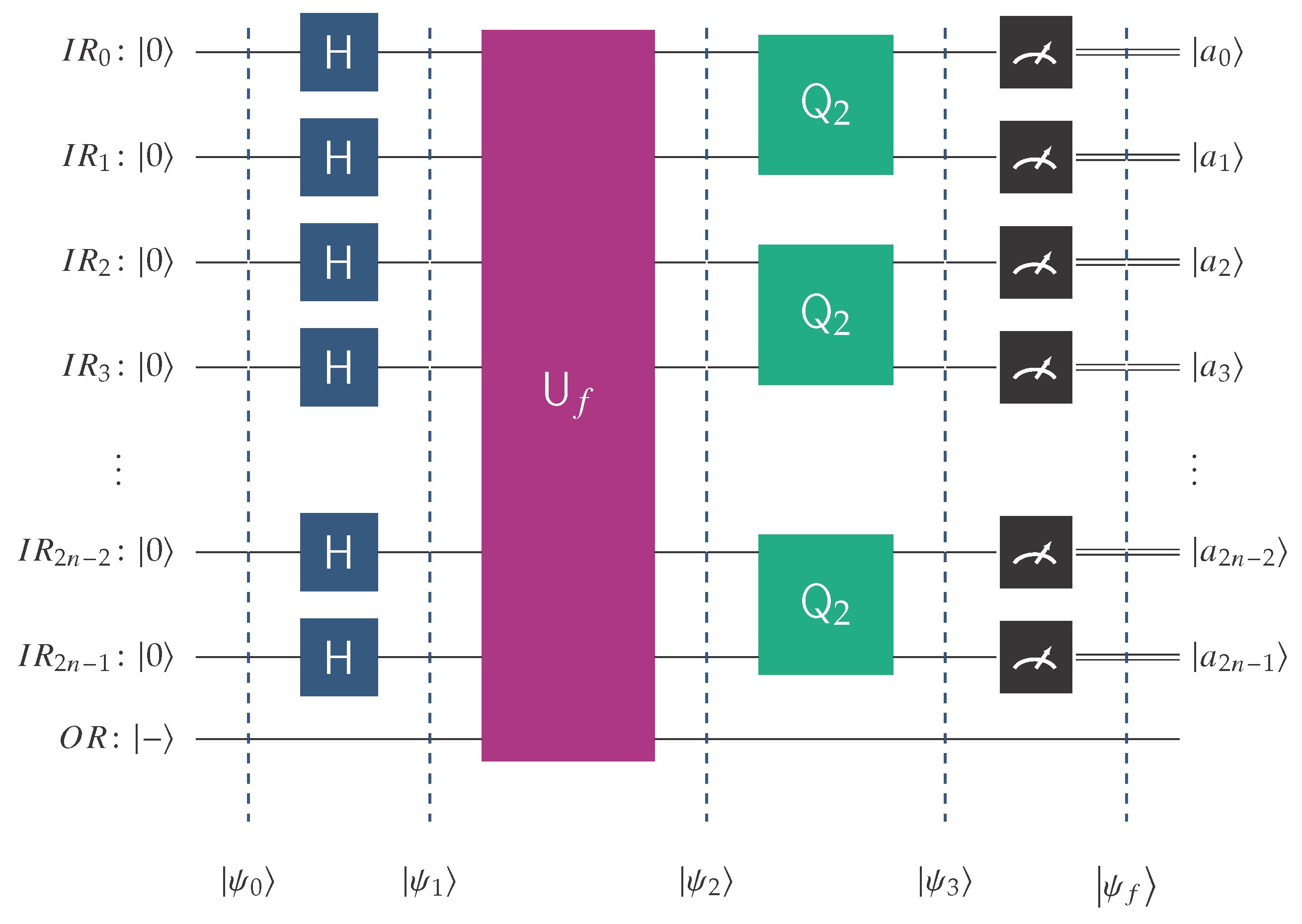
The first member of this family, the QCPC2 quantum circuit, takes the form depicted in Figure 7 and can classify the Boolean functions in . The general QCPC2n quantum circuit takes the abstract form visualized in Figure 11. It is endowed with the oracle encoding the behavior of the Boolean function f, which is promised to belong to .
Therefore, the abstract quantum circuit that implements the BFPQC algorithm for the classification of the class of Boolean functions
, is outlined in
Figure 11. To avoid any ambiguity, we explain the notation used in this figure.
is the quantum input register that contains qubits and starts its operation at state .
is the single-qubit output register initialized to |−〉.
H is the Hadamard transform.
is the unitary transform corresponding to the oracle for the unknown function, f. The latter is promised to be an element of .
is the fundamental building block of
, as evidenced by Equation (
20).
Classification works as follows: the Boolean functions contained in are enumerated as . Assuming the oracle encodes the function with index i, the outcome of the final measurement of the quantum circuit QCPC2n after the action of the classifier will be , where is the binary representation of the index i, i.e., one of the basis kets of the computational basis. Our algorithm is optimal because it requires just a single query to classify the hidden function.
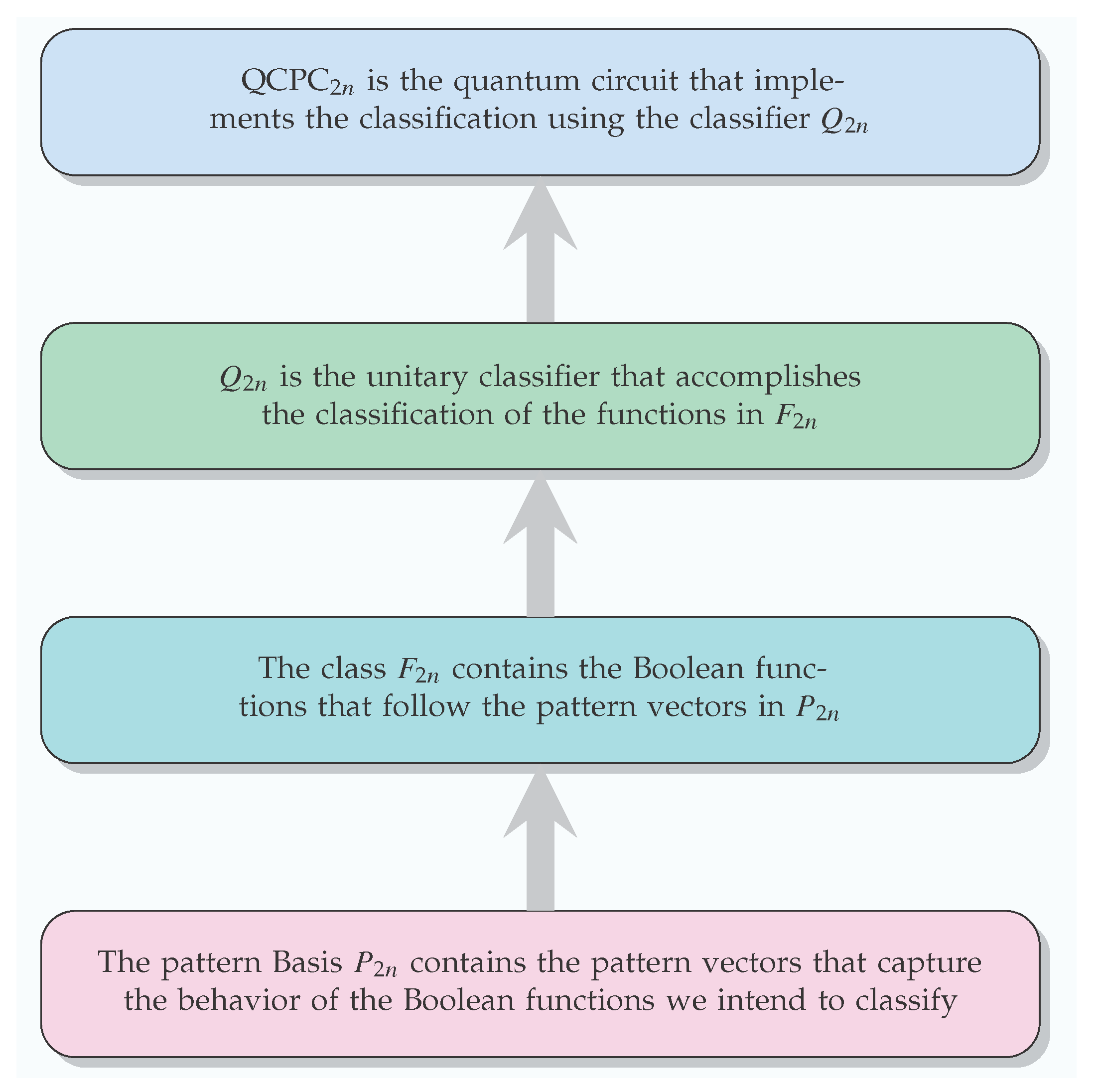
The method we used to devise the BFPQC algorithm is visualized in
Figure 12. We are confident that this methodology is general and fruitful, in the sense that it can be used as a starting point to define additional quantum classification algorithms by establishing different hierarchies of pattern bases and classifiers.
We close this section by giving a more interesting example targeting functions of .
Example 4 (Classifying functions of
).
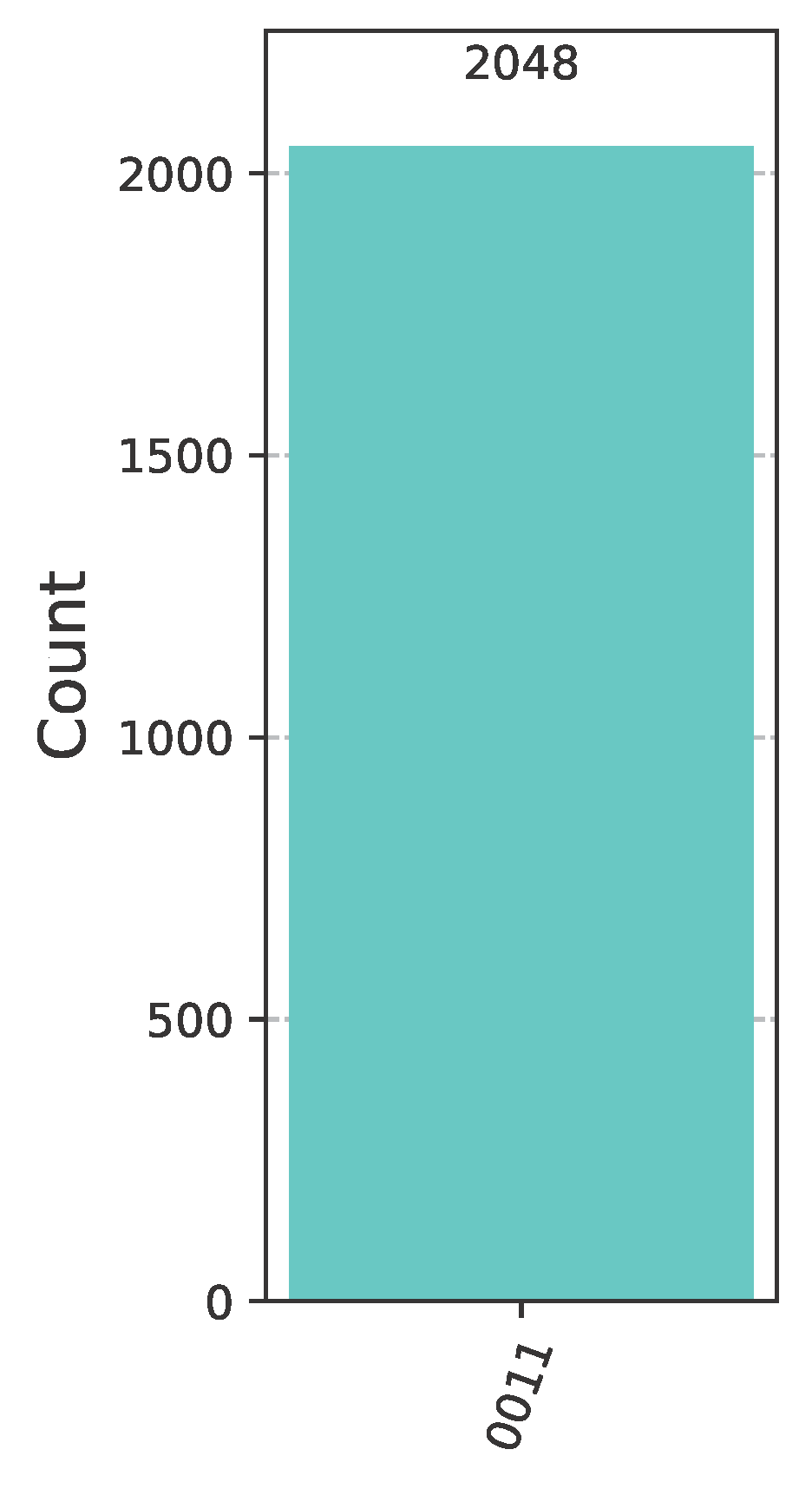
Let us assume that Bob has to choose a Boolean function from , the promised class of functions in this case. Say that Bob chooses , the behavior of which is given by the pattern vector , listed in Example 2. Alice makes her move by employing the classifier . In this case, the concrete implementation in Qiskit [41] of the general quantum circuit of Figure 11 takes the form shown in Figure 13, where Bob uses the oracle for the function and Alice the classifier .After the oracle, and before the action of the classifier, the state of the system is shown in Figure 14. After the action of the classifier, the state of the system is just . Therefore, measuring the quantum circuit depicted in Figure 13 will output the bit vector 0011 with probability 1 (as corroborated by the measurements contained in Figure 15), which is the binary representation of the index of . Alice surely wins the game, as anticipated. Execution on IBM quantum computers.
After validating the correctness of the quantum circuit depicted in
Figure 13 via simulation, we used Qiskit to execute it on a real IBM quantum computer. At the moment of running the experiment, the backends that were available to us (via our free-tier account) were
ibm_brisbane (127 qubits) and
ibm_sherbrooke (127 qubits). Both IBM Brisbane and IBM Sherbrooke quantum computers are 127-qubit backends based on IBM’s Eagle r3 processor, making them architecturally similar. They are designed for utility-scale quantum computing, meaning that they are capable of running complex algorithms and physics simulations that push the boundaries of classical computation, and suit our circuit’s modest requirements (number of qubits and number of gates). Each time we picked the least busy backend with enough qubits using the typical command:
backend = service.least_busy(simulator=False, operational=True,
min_num_qubits=5)
The operation of the BFPQC algorithm is formalized in Theorem 1.
Theorem 1 (Classification via the BFPQC algorithm). Let , be a Boolean function contained in the class = …. Upon measuring the quantum circuit QCPC2n containing the oracle for and the unitary classifier , we obtain with a probability of , where is the binary representation of the index i, and is one of the basis kets of the computational basis.

