Article

Vibration Reduction of Permanent Magnet Synchronous Motors by Four-Layer Winding: Mathematical Modeling and Experimental Validation

1
Department of Automotive Engineering, Yeungnam University, Gyeongsan 38541, Republic of Korea
2
Department of Automotive Engineering, Honam University, Gwangju 62399, Republic of Korea
3
Advanced Mobility System Group, Korea Institute of Industrial Technology, Daegu 42994, Republic of Korea
4
Department of Mechanical, Robotics, and Energy Engineering, Dongguk University, Seoul 04620, Republic of Korea
5
Department of Electrical Engineering, Soonchunhyang University, Asan 31538, Republic of Korea
*
Authors to whom correspondence should be addressed.
These authors contributed equally to this work.
Mathematics 2025, 13(10), 1603; https://doi.org/10.3390/math13101603
Submission received: 4 April 2025 / Revised: 9 May 2025 / Accepted: 12 May 2025 / Published: 13 May 2025
(This article belongs to the Special Issue Advanced Modeling and Design of Vibration and Wave Systems)

Abstract

:
This paper proposes a vibration reduction method for fractional slot concentrated winding (FSCW) permanent magnet synchronous motors (PMSMs) by applying a four-layer winding configuration. The radial electromagnetic force (REF), particularly its low space-harmonics, causes significant vibration in PMSMs. These low-order REF components are influenced by sub-harmonics in the airgap magnetic flux density (MFD), which occur at frequencies lower than the fundamental component generated by the armature magnetomotive force (MMF) in FSCW PMSMs. To mitigate these sub-harmonics in the MFD, the four-layer winding is applied to the FSCW PMSM. As a result, the overall vibration of the motor is reduced. To verify the effectiveness of the four-layer winding, both electrical and mechanical characteristics are compared among motors with conventional one-, two-, and, proposed, four-layer windings. Finally, the three motors are fabricated and tested, and their vibration levels are experimentally evaluated.

1. Introduction

Electric motors using fractional slot concentrated winding (FSCW) achieve higher torque density and efficiency due to their high winding factor and compact end-winding length [1,2,3]. Moreover, the FSCW motor has advantages such as flux weakening capability and low cogging torque [3,4,5]. Based on these advantages, the FSCW motor is used in various applications: Vehicle applications, ship propulsion, home appliances, etc. [1,5,6,7,8,9]. To enhance the performance of the FSCW motor, various studies on the FSCW motor have been conducted. In [1], the thermal performance of the FSCW motor with the integral slot distributed winding was analyzed. References [10,11,12] proposed analytical modeling to predict the performances of the FSCW motor more accurately. In [13], the FSCW motors were designed for various combinations of poles and slots, and their performances were compared. In [14,15], various rotor types were applied to the FSCW motor. The Y-type rotor topology was proposed in [14], and the consequent pole rotor was applied in [15]. Reference [16] researched the vernier motor-applied FSCW.
However, the FSCW motor has a high-order harmonic in the magnetomotive force (MMF), which causes a high eddy current loss [17,18]. Several methods have been proposed to reduce high-order harmonics in FSCW motors. One approach involves modifying the rotor structure. For example, reference [19] applied slits to the rotor, while [20] introduced surface notches to reduce rotor eddy current loss. Another approach changes the stator slot configuration. In [21], the number of slots was adjusted to reduce space-harmonics. Additionally, ref. [22] proposed a hybrid winding method combining star and delta connections while modifying the slot number to suppress harmonics. The four-layer winding was proposed to reduce the space-harmonics of the FSCW motor in [23,24,25,26]. Furthermore, the six-layer winding was proposed in [27], but the average torque of the six-layer winding was reduced more than that of the four-layer winding.
In these previous studies, the objective of reducing space-harmonics was to enhance the electrical characteristics, such as reducing the rotor eddy current loss and torque ripple. That is, references [23,24,25,26,27] mainly focused on electromagnetic performance improvement by minimizing high-order harmonics in the MMF and flux distribution. While these studies made meaningful contributions in reducing electrical losses and improving torque quality, they did not consider the mechanical implications of harmonic components, such as their effect on vibration.
Additionally, the FSCW motor has an inevitable sub-harmonic and high space-harmonics of the magnetic flux density (MFD) in the airgap generated by armature MMF. The sub-harmonics of the MFD in the airgap generate the lowest vibration order corresponding to the space-harmonic of the radial electromagnetic force (REF). Since the low-order harmonic component significantly affects the vibration of the FCSW PMSM, the sub-harmonic of MFD in the airgap should be reduced. Therefore, the reduction of the harmonics of the FSCW motor should be addressed to enhance both the electrical and mechanical characteristics.
This paper proposes applying the four-layer winding to reduce the vibration of the FSCW motor. Most approaches for minimizing the harmonics in the MFD of the FSCW motor are to change the motor shape. These methods inevitably accompany optimization techniques and redesigns. However, unlike previously mentioned methods to reduce the harmonics in the MFD, the four-layer winding has the advantage that the harmonics in the MFD can be reduced by simply modifying the layout of the armature winding only. Therefore, the suggested method is time- and cost-effective because it can be implemented directly on the manufactured motor and simplifies the design process.
Thus, to expand the advantages and utility of the four-layer winding, this paper analyzes the impact of the four-layer winding on the vibration characteristics of the FSCW motor and verifies its effectiveness in reducing vibration. As mentioned earlier, in the previous studies on the four-layer winding [23,24,25,26,27], the four-layer winding was applied to improve only the electrical characteristics.
In contrast to previous studies focusing solely on electrical performance, this paper applies the four-layer winding to enhance mechanical characteristics—specifically, reducing vibration caused by sub-harmonic components in the radial electromagnetic force. This extends the application scope of prior research by bridging electromagnetic optimization with mechanical robustness, which has not been previously addressed.
The contents are as follows. First, the sub-harmonic and vibration order of the FSCW permanent magnet synchronous motor (PMSM) is introduced. Second, the four-layer winding is briefly introduced. Next, the four-layer winding is applied to the PMSM with 10 poles–12 slots, and the electrical and mechanical characteristics according to the winding layout (one-, two-, and four-layer) are compared. Finally, the motors applying the one, two-, and four-layer winding are fabricated, and the test is conducted to validate the effectiveness of the proposed method.

2. Concerns Regarding FSCW PMSMs

As mentioned earlier, the FSCW PMSM has the advantages of high-power density, low torque ripple, and cogging torque, but has the disadvantage of poor mechanical characteristics. This is because the FSCW PMSM has a low vibration order. Here, the vibration order corresponds to the space-harmonic order of the REF that causes the displacement. Since the displacement according to the vibration order is the same as (1), the REF with the low vibration order causes a large vibration [28].
d 1 r 4
where d is the displacement of the electric motor; r is the vibration order of the REF. The symbol ∝ means that the displacement magnitude decreases rapidly with increasing vibration order, following an inverse-fourth-power relationship.
The REF with the low vibration order of the FSCW PMSM is generated by the sub-harmonic of the MFD in the airgap by the armature MMF of the FSCW PMSM. Here, the sub-harmonic represents a harmonic having a lower frequency than the fundamental component among the harmonics. This section describes the vibration order by the sub-harmonic in the MFD generated by the armature MMF of the FSCW PMSM in detail.

2.1. Sub-Harmonics in Airgap Magnetic Flux Density of FSCW PMSM

In the PMSM, the space distribution in the MFD by the armature MMF depends on the pole–slot combinations. The slot number per pole and phase number is (2), and the space-harmonic order in the MFD by the armature MMF is (3) [29].
q = S 2 p m = z j
ν = 1 ± 2 m k j       k = 0 ,   1 ,   2 ,
where q is the stator slot per pole and phase; S is the stator slot; p is the pole-pair; m is the phase; z and j are coprime integers representing the irreducible form of q; and ν is the space-harmonic order in the airgap MFD by the armature MMF in the electrical one period.
Table 1 shows the space-harmonic order in the airgap MFD by the armature MMF according to the pole–slot combinations using (2) and (3). In Table 1, the bold underlined numbers are the sub-harmonic. The FSCW PMSMs have sub-harmonics, while there are no sub-harmonics in the 2n poles–3n slots and 2n poles–12n slots, which are commonly used pole–slot combinations. These sub-harmonics of the FSCW PMSM generate the REF with the low vibration order. The REF is briefly described in the next section, and the vibration order derived from the REF is shown according to the pole–slot combination.

2.2. Vibration Order in Radial Electromagnetic Force of FSCW PMSM

Since the tangential component in MFD is typically much smaller than the radial component, the REF density is given as (4) by the Maxwell stress tensor.
P r = B g , r 2 B g , t 2 2 μ 0 B g , r 2 2 μ 0
where Bg,r and Bg,t are the radial and tangential component of airgap MFD, respectively, and μ0 is the vacuum permeability.
The radial MFD is generated by the PM and armature MMF. The teeth–slot structure influences the distribution of the radial airgap MFD. To reflect this effect due to the teeth–slot structure, the relative specific permeance is taken into account in the airgap MFD in a smooth airgap. Therefore, the radial MFD is expressed as (5). By substituting (5) into (4), (6) is obtained.
B g , r = B g , m + B g , a Λ a
P r = B g , m + B g , a 2 Λ a 2 2 μ 0
where Bg,m and Bg,a are the radial MFD by the PM and armature MMF, respectively; Λa is the relative specific permeance.
The radial MFD by the PM, armature MMF, and the relative specific permeance are expressed as (7)–(9).
B g , m θ , t = μ = 1 B m μ cos μ p θ ω μ t + ϕ μ
B g , a θ , t = ν = 1 B a ν cos ν p θ ω t
Λ a θ = 1 + k = 1 , 2 A k cos k S θ
where μ is the space-harmonic order; B and ωμ are the peak value and electrical angular velocity of μth component in the airgap MFD by the PM; B is the amplitude of the νth component in the airgap MFD by the armature MMF; and ϕμ is the phase difference between the μth harmonic in the MFD by PM and the same order harmonic in MFD by the armature MMF.
The vibration order can be obtained by Substituting (7)–(9) into (6). The vibration orders and frequencies of the REF presented in Table 2 are based on the findings summarized in [30]. In Table 2, f and n are the frequency and time-harmonic order in the input armature current, respectively. At this time, since the input armature current is assumed to be a sinusoidal waveform, n is 1 in this paper. In the PMSM, the space-harmonic order in the airgap MFD by the PM is generally a positive odd number, and that by the armature MMF is calculated using (3). The vibration order determined from Table 2 according to the various pole–slot combinations is summarized in Table 3 at twice the line frequency. As can be seen from Table 1 and Table 3, low vibration orders, which have a number smaller than the number of the poles, are affected by the space-harmonics of the armature MMF, especially the sub-harmonics. Therefore, to decrease the REF at the low vibration order with a significant impact on vibration, the sub-harmonic in the airgap MFD by the armature MMF should be reduced.

3. Proposed Four-Layer Winding for Vibration Reduction

As mentioned previously, the four-layer winding is the method used to reduce the space-harmonics by decreasing the winding factor of the armature MMF. In [23,24], the four-layer winding was applied to reduce torque ripple, which is mainly caused by the interaction between the harmonic components of the armature and PM MMFs. In this paper, the same four-layer winding structure is applied to reduce vibration, specifically that induced by sub-harmonic components in the airgap magnetic flux density generated by the armature MMF.

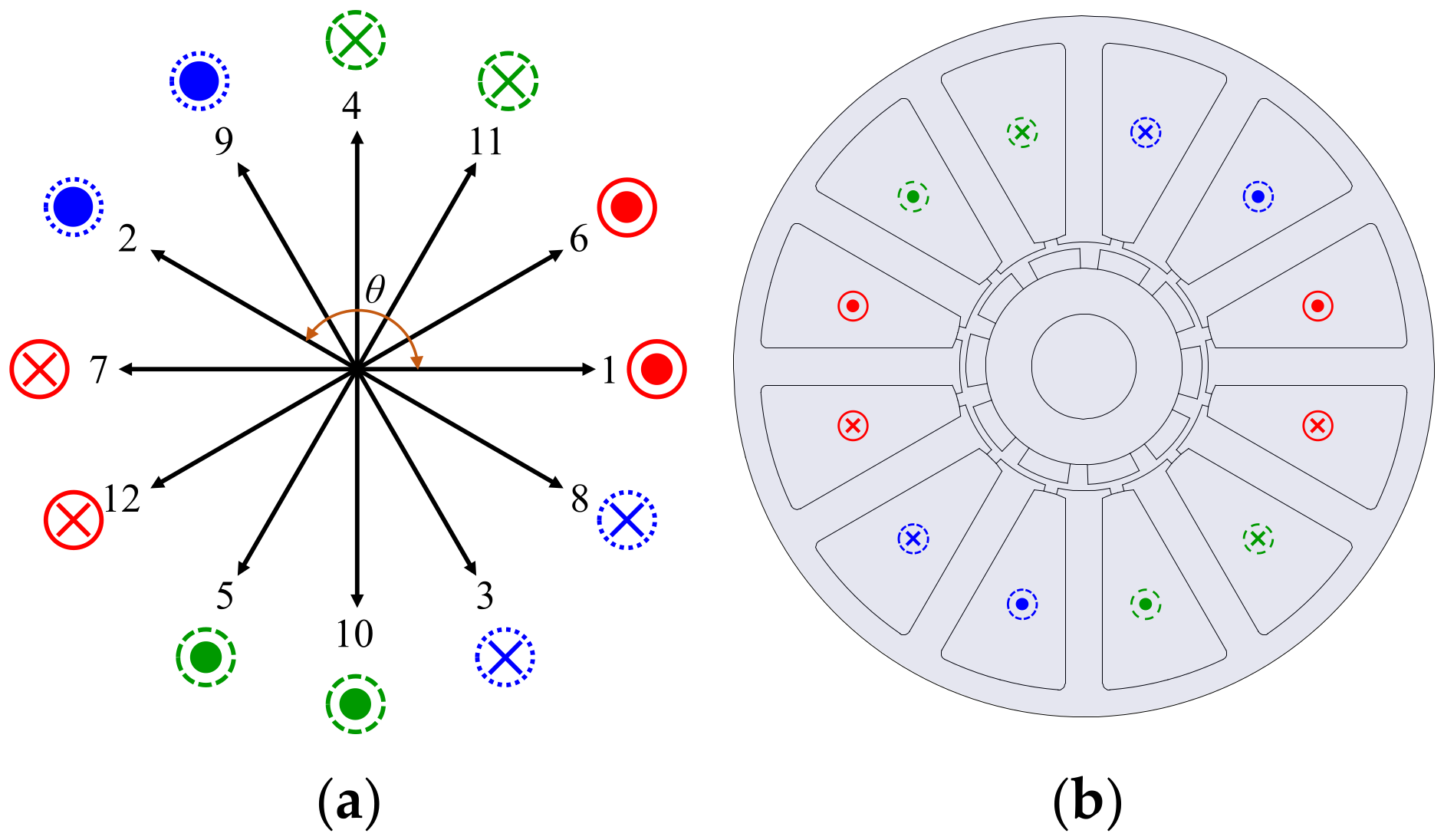
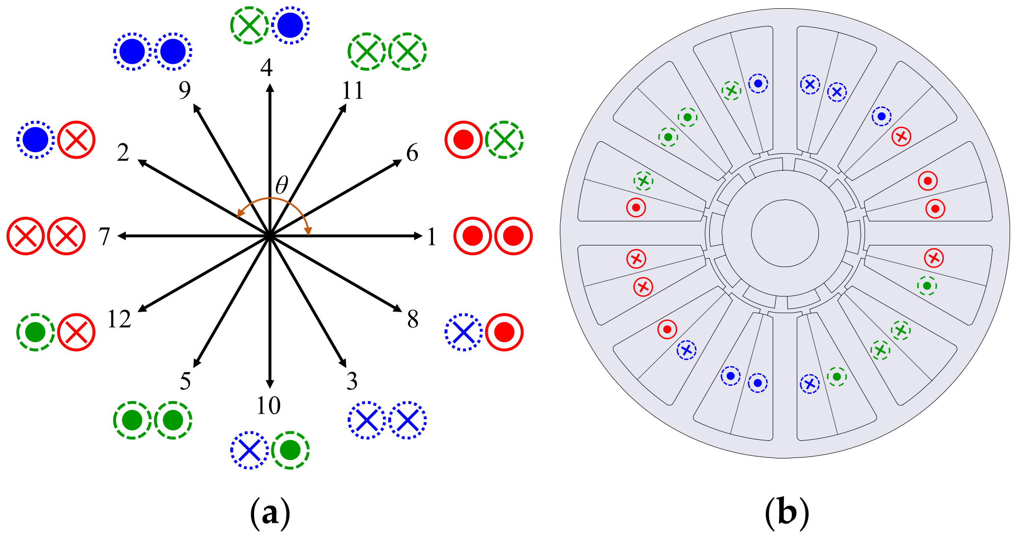
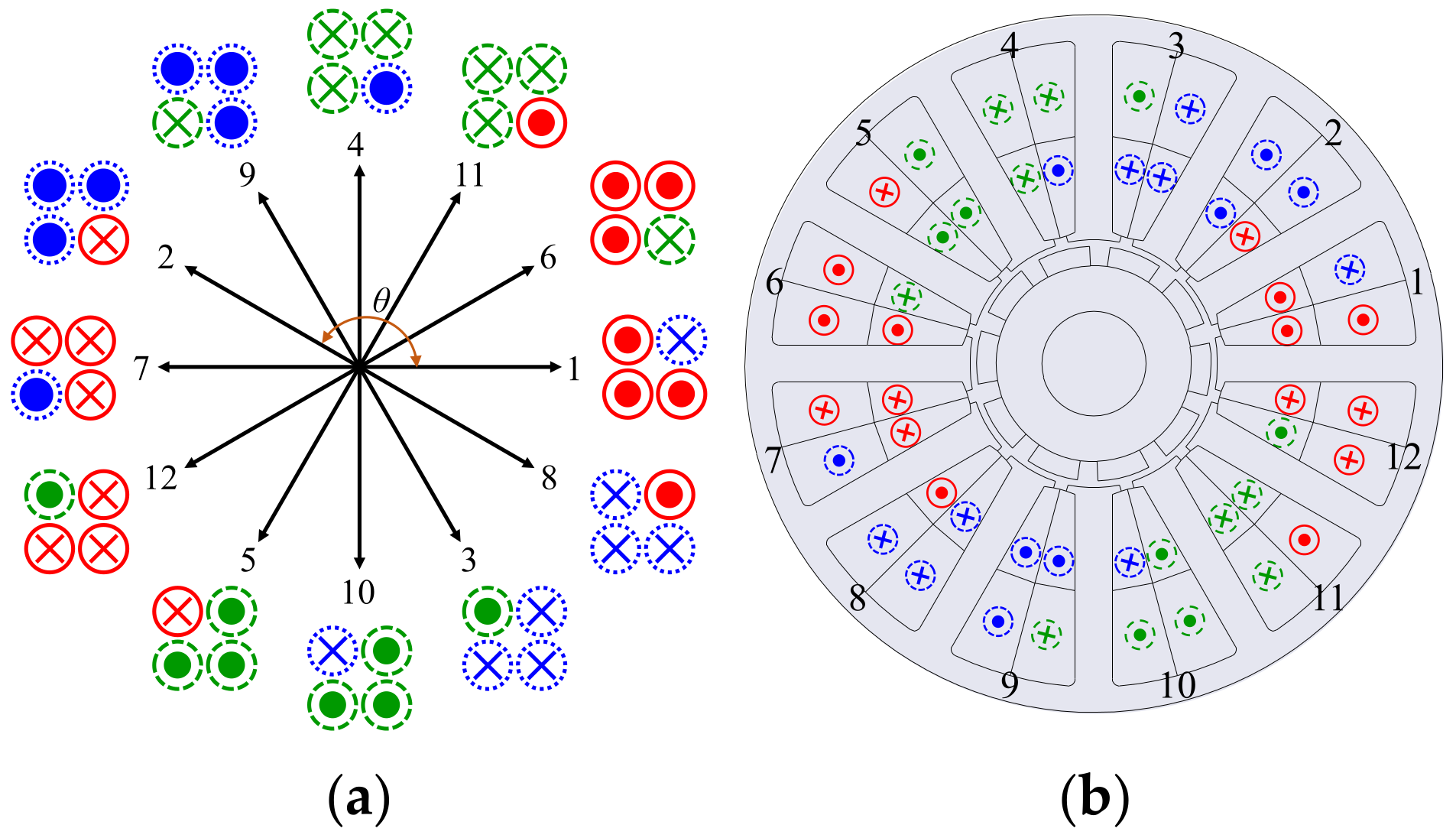
3.1. Winding Layout by Winding Methods

In this section, the winding layout of the four-layer winding is described using the star of slots theory [23], and the one-layer, two-layer, and four-layer winding of 10 poles–12 slots are explained as an example. The star of slots of the one-layer winding of 10 poles–12 slots is shown in Figure 1a. The 10 poles–12 slots have 12 arrows, where each arrow means the slots of the number written upon each arrow. For example, slots 1 and 2 are mechanically adjacent to each other but electrically have a phase difference of (10). Since the star of slots should be considered the electrical phase difference, slots 1 and 2 are arranged to have the phase difference of θ, as shown in Figure 1a. The other slots are also arranged in the same way in the star of the slots.
θ = 2 π p S
where θ is the electrical phase difference between the mechanically adjacent slots. The number of arrows each phase can have according to the number of layers is expressed as (11).
a p = S l m
where ap is the number of arrows that each phase can have according to the layer number; l is the layer numbers.
The arrows and the directions of the coil sides are appropriately selected for each phase so that the vector sum between arrows by the number calculated from (11) becomes the maximum. The arrangement within the star of slots of each phase of the one-layer winding is demonstrated in Figure 1a. The shape and color of the circles next to the number mean phase, and the red straight line, blue dot line, and green dash line are the U, V, and W phases, respectively. Also, the number of circles next to the number means the number of layers. Since the number of circles is 1, it can be seen that Figure 1a is the one-layer winding. The symbols ‘O’ and ‘X’ in the circle mean the positive and negative directions of the coil side, respectively. Figure 1b shows the winding layout of the one-layer winding of 10 poles–12 slots. The star of slots and winding layout in the two-layer winding of 10 poles–12 slots is demonstrated in Figure 2. As demonstrated in Figure 2a, the star of slots of the two-layer winding is similar to that of the one-layer winding, but the number of circles of the two-layer winding is different from that of the one-layer winding. Figure 3a,b show the star of slots and winding layout of the four-layer winding of 10 poles–12 slots, respectively. As shown in Figure 3b, the windings on each phase of the four-layer winding are more distributed than those of other windings, which affects the winding factor. In the following sections, the armature magnetomotive force according to the winding method is mathematically derived to explain the generation mechanism of sub-harmonics and the effect of the proposed four-layer winding.

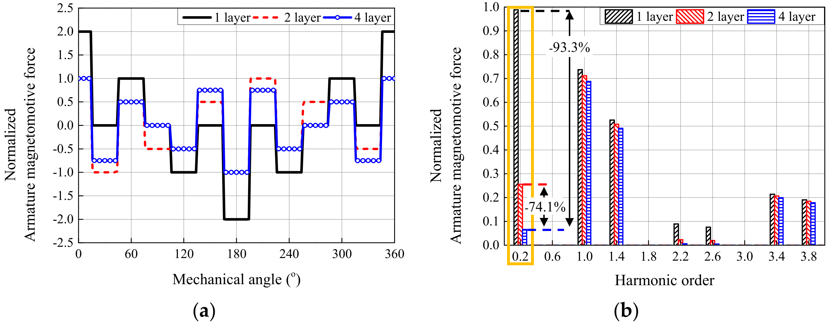
3.2. Analysis of Armature Magnetomotive Force by Winding Methods

As discussed earlier, the MFD of sub-harmonics generated by the armature MMF negatively affects motor vibration by producing the REF with a low vibration order. To clarify the generation mechanism of sub-harmonics and evaluate the effect of four-layer winding on the sub-harmonics of the MFD, the armature MMF corresponding to the winding method is mathematically formulated.
The armature MMF generated by a single coil in one phase is used to derive the resultant armature MMF of the three-phase winding. Figure 4 depicts the distribution of the armature MMF generated by a single coil. For 10-poles–12-slots with a coil pitch, and α of 30 degrees, the armature MMF distribution can be expressed using a Fourier series as follows.
f ( θ ) = a 0 + n = 1 ( a n cos n θ + b n sin n θ ) = n = 1 ( a n cos n θ )     ( a 0 = b n = 0 )
a n = 1 π π π f ( θ ) cos n θ d θ             = 2 π 0 α / 2 N c i 2 π α 2 π cos n θ d θ 2 π α / 2 π N c i α 2 π cos n θ d θ             = 2 π N c i ν sin n π 12             ( α = π 6 )
where Nc is the turn number of the single coil; i is the armature input instantaneous time-varying current, while Im denotes the peak amplitude of that current.
The armature MMF for a single phase, reflecting the phase shifts of the coils based on the previously introduced layer-specific winding layout, is expressed as follows, where all terms with nnn as an even number become zero.
f 1 = n = 1 a n cos n θ n = 1 a n cos n ( θ π ) = n = 1 , 3 , 5 4 N c i n π sin n π 12 cos n θ
f 2 = n = 1 a n cos n θ ν = 1 a n cos n θ π 6 n = 1 a n cos n ( θ π ) + n = 1 a n cos n θ 7 π 6             = n = 1 , 3 , 5 8 N c i n π sin n π 12 2 sin n θ n π 12
f 4 = n = 1 a n cos n θ 1 2 n = 1 a n cos n θ π 6 1 2 n = 1 a n cos n θ + π 6                       n = 1 a n cos n ( θ π ) + 1 2 n = 1 a n cos n θ 7 π 6 + 1 2 n = 1 a n cos n θ 5 π 6             = n = 1 , 3 , 5 4 N c i n π sin n π 12 1 cos n π 6 cos n θ
Finally, the armature magnetomotive force (MMF) for the three phases, accounting for the 120-degree phase-shifted coil arrangement and three-phase currents, is expressed as follows.
f 1 A = n = 1 , 3 , 5 4 N c I m cos ω t n π sin n π 12 cos n θ f 1 B = n = 1 , 3 , 5 4 N c I m cos ω t 2 π 3 n π sin n π 12 cos n θ 2 π 3 f 1 C = n = 1 , 3 , 5 4 N c I m cos ω t + 2 π 3 n π sin n π 12 cos n θ + 2 π 3
f 2 A = n = 1 , 3 , 5 , 8 N c I m cos ( ω t ) n π sin n π 12 2 sin n θ n π 12 f 2 B = n = 1 , 3 , 5 , 8 N c I m cos ω t 2 π 3 n π sin n π 12 2 sin n θ 2 π 3 n π 12 f 2 C = n = 1 , 3 , 5 , 8 N c I m cos ω t + 2 π 3 n π sin n π 12 2 sin n θ + 2 π 3 n π 12
f 4 A = n = 1 , 3 , 5 4 N c I m cos ( ω t ) n π sin n π 12 1 cos π 6 cos n θ f 4 B = n = 1 , 3 , 5 4 N c I m cos ω t 2 π 3 n π sin n π 12 1 cos n π 6 cos n θ 2 π 3 f 4 C = n = 1 , 3 , 5 4 N c I m cos ω t + 2 π 3 n π sin n π 12 1 cos n π 6 cos n θ + 2 π 3
The resultant armature MMF is obtained by summing the MMFs of the three phases. Figure 5 illustrates the distribution of the armature MMF according to different layers and its harmonic analysis results at t = 0. In four-layer winding, although the fundamental armature MMF slightly decreases, the sub-harmonics are reduced by 93% and 74% compared to those in single-layer and two-layer windings, respectively.
In the next section, the winding factors, enabling a quantitative comparison of harmonic magnitudes between different layers, are analyzed.

3.3. Winding Factor by Winding Methods

The change in the winding factor caused by applying the four-layer winding is explained. The winding factor of the νth harmonic order is expressed as (20).
k w ν = k p ν k d ν
where k is the winding factor of the νth harmonic order; k is the distribution factor of the νth harmonic order; and k is the pitch factor of the νth harmonic order. The pitch and distribution factors of the νth harmonic order are summarized in Table 4.
The winding factors according to the layer numbers calculated using (20) are also indicated in Table 4. The larger the number of layers, the lower the winding factor. Since the value of the cosine function is less than 1, it is expected that the winding factors in all harmonics in the four-layer winding are less than those in other windings. In the case of the fundamental winding factor that contributes to torque and power, that of the four-layer winding is decreased by 7% and 3% compared with that of the one- and two-layer windings, respectively. On the other hand, in the case of the sub-harmonic (0.2-order) which contributes to the low vibration order, the winding factor of the four-layer winding is reduced by about 93% and 74% compared with that of the one- and two-layer windings, respectively. These results are consistent with the trends previously noted in the armature MMF. Therefore, it is thought that the vibration reduction, applying the four-layer winding, is reasonable because the sub-harmonic in the airgap MFD by the armature MMF, which greatly affects the low vibration order, is reduced.

3.4. Applicability of Four-Layer Winding

The four-layer winding increases the number of coil sides in the slot to four, thereby reducing the sub-harmonics that contribute greatly to vibration. However, the four-layer winding is not applicable to all pole–slot combinations. The applicability of four-layer winding can be confirmed through the star of slot theory introduced above.
The arrows in the star of the slot are divided into positive and negative directions. To apply four-layer winding, at least two arrows per direction (positive or negative) are required. Since the number of arrows per phase is S/(mτ), and each phase has two directions (positive and negative), the four-layer winding can be applied only when S/(2mτ) > 1 is satisfied. Here, τ is defined as the machine periodicity as the greatest common divisor of the number of pole pairs and the number of slots [23].
For example, two poles–three slots (including all 2:3 pole–slot ratios) cannot apply four-layer winding because it has one arrow per phase per direction. However, it is applicable to all pole–slot combinations with sub-harmonics in Table 1. In this paper, the 10 poles–12 slots combination, which is the most studied multi-layer winding, is adopted.

4. FEA-Based Comparison of Electromagnetic and Vibration Characteristics

The electrical and mechanical characteristics according to the three winding methods are compared in this section. To examine the electrical characteristics, the nonlinear electromagnetic field FEA using in-house code is conducted. To review the mechanical characteristics, a nonlinear mechanical field FEA using Ansys is performed.
The motor type and the combination of the number of poles and slots of the motors used in the comparison are the PMSM and 10 poles–12 slots, respectively. The outer diameters of the rotor and stator are 36 mm and 107 mm, respectively. The stack length is 44 mm. The core material of the rotor and stator is 50PN470, which has a 0.5 mm thickness and an iron loss of 4.7 kW/kg at 1.0 T and 50 Hz. The remanence and recoil permeability of the PM are 1.29 T at 20 °C and 1.05, respectively. Figure 6 illustrates the configuration of the three models. Also, the model information is indicated in Table 5.

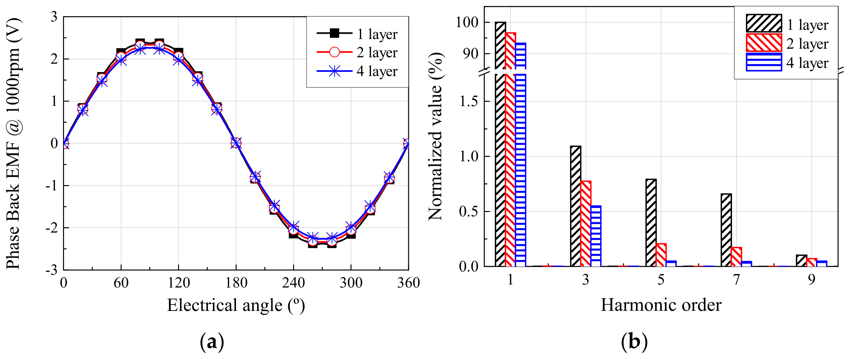
4.1. Back-EMF and Torque Characteristics via FEA

The electrical characteristics including the back electro-motive force (EMF) and torque of the four-layer winding are compared with those of the one-layer and two-layer windings. As mentioned in Section 3.3, the winding factors of the four-layer winding are more reduced than those of other windings. In the case of the winding factor of the fundamental component, which contributes to the average torque, the winding factor of the four-layer winding is about 7% and 3% smaller compared to that of the one-layer and two-layer windings, respectively. Therefore, it is obvious that the torque of the four-layer winding is worse than those of other windings under the same input current condition. However, since other harmonics except for the fundamental component of the four-layer winding are also reduced compared with those of other windings, it can be expected that the torque ripple of the four-layer winding is better than those of other windings.
First, the back EMF of the three winding methods is compared. The back EMF waveform of the three winding methods is illustrated in Figure 7a. The back EMF waveform between the three winding methods is not significantly different. Figure 7b shows the result of the harmonic analysis of the back EMF depending on the winding methods. Compared with other windings, the fundamental component in the back EMF of the four-layer winding is reduced, but the harmonics of the back EMF of the four-layer winding are also reduced, which slightly reduces the total harmonic distortion (THD) of the back EMF.
Next, the electrical characteristics under the load condition according to the winding methods are compared, such as input current and torque ripple. Since the average torque and input current in the id = 0 control have a relationship of (21), the four-layer winding needs a larger current to achieve the same torque due to the decrease in the back EMF.
T = m e 1 , r m s i 1 , r m s ω m
where T is the average torque; e1,rms is the rms value of the fundamental component of the back EMF; i1,rms is the rms value of the fundamental component of the input current; and ωm is the mechanical angular velocity.
As a result, Figure 8 shows the torque waveforms in models with three winding methods. As demonstrated in Figure 8, the four-layer winding’s torque ripple is the lowest, because the THD in the back EMF of the four-layer winding is the lowest among the three models. Also, the copper loss of the four-layer winding is larger than that of other windings. However, the efficiency of the single-layer winding is 89.7%, which is lower than the 90.6% and 90.3% of the two-layer and four-layer winding. This is because the iron loss of the one-layer winding is larger than other windings. The electrical characteristics according to the winding methods are summarized in Table 6.

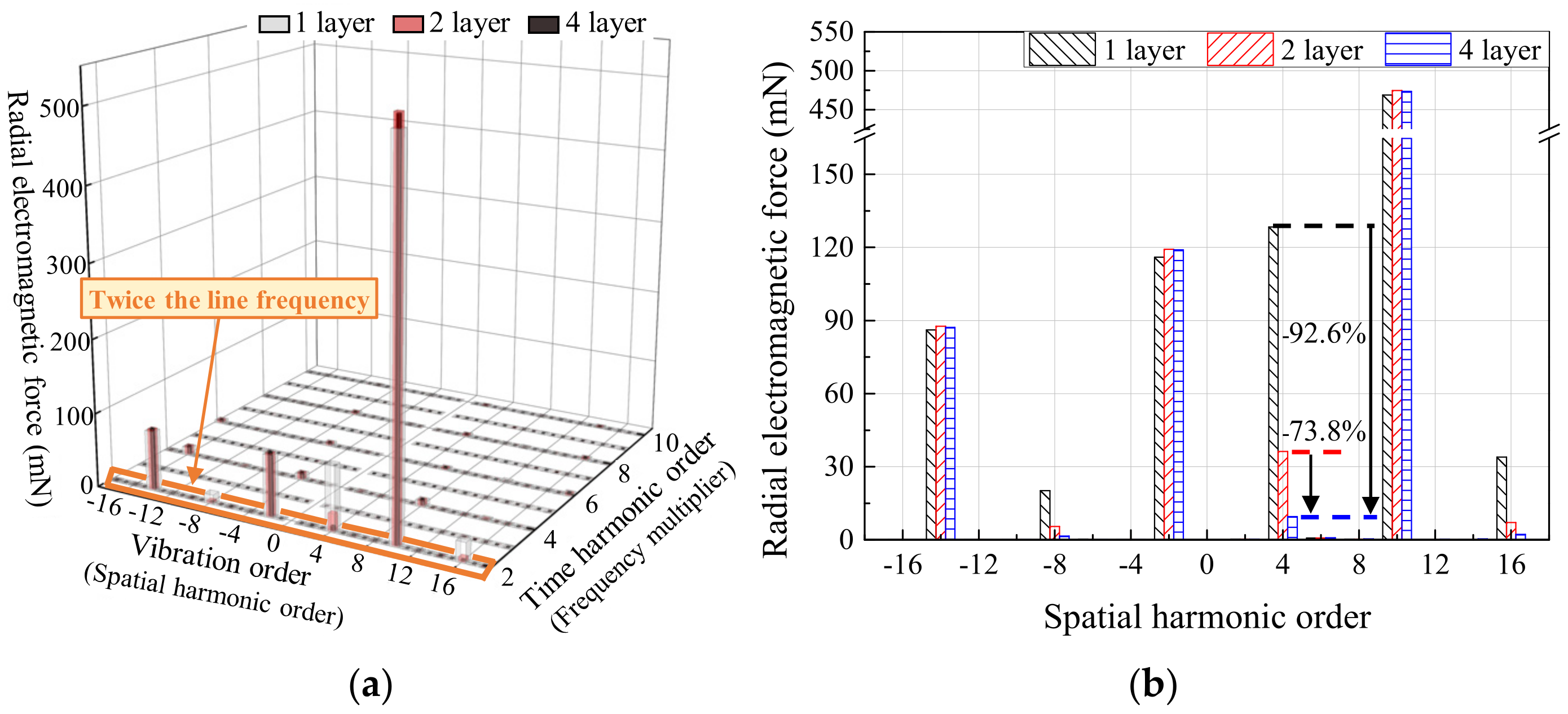
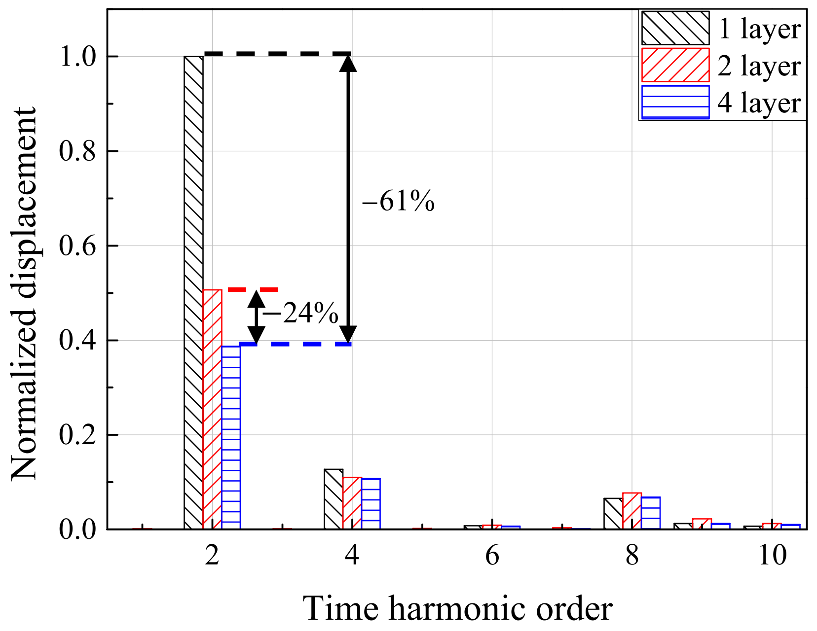
4.2. Vibration Characteristics Based on FEA

The vibration characteristics of the electric motors according to three winding methods are compared, such as REF and displacement. Figure 9 shows the vibration simulation process for calculating the displacement of the motor. First, the airgap MFD is calculated using the electromagnetic field FEA. Next, the REF is calculated using (4) and the previously calculated airgap MFD. Finally, The REF is applied to the stator of the motor, and the displacement is calculated through vibration simulation using mechanical field FEA. At twice the line frequency, since the REF of the low vibration order due to the sub-harmonics of the armature MMF is generated and the vibration of the motor is generally the largest, the mechanical characteristics at twice the line frequency are examined.
According to the winding method, the airgap MFD, which produces the REF at twice the line frequency, is compared. The source of the airgap MFD is divided into the PM and armature MMF. As mentioned previously, since the input current is assumed to be sinusoidal, the time-harmonic order in the airgap MFD by the armature MMF is 1. Therefore, as shown in Table 2, the time-harmonic in the airgap MFD by PM is 1 or 3. However, since the amplitude of the third time-harmonic order component in the airgap MFD by PM is very small, only the first-order time-harmonic in the airgap MFD by PM is considered. Figure 10a,b show the waveforms and magnitude according to the space-harmonics in the first-order time-harmonic in the airgap MFD by PM and armature MMF, respectively. Since the MMF of the PM is the same regardless of the winding method, the magnitude of the space-harmonics of the airgap MFD due to the PM is the same. However, the magnitude of the space-harmonic in the airgap MFD by armature MMF according to the winding method is different in each. As shown in Figure 10b, 0.2-order space-harmonic in the airgap MFD by armature MMF is remarkably reduced by applying the four-layer winding as expected. In the case of the four-layer winding, 0.2-order space-harmonic in the airgap MFD by the armature MMF is decreased by 93.1% and 74.2% compared with that of the one- and two-layer windings, respectively.
Next, Figure 11a presents the spectral analysis results of the REF, which varies with time and space. The time-harmonic order refers to multiples of frequency [31]. Once the line frequency is set based on the rotational speed of the motor, the frequencies of the REF are also determined. For example, a motor operating at 2500 rpm has a line frequency of approximately 208 Hz, and the REFs occur at even multiples such as 416 Hz, 832 Hz, and so on. As seen in Figure 11a, the dominant frequency of the REFs generated in all three models is twice the line frequency. Figure 11b illustrates the REF as it corresponds to the vibration order at twice the line frequency. As shown in Figure 11b, overall, the REF of the four-layer winding is reduced compared to that of the other windings, and especially, the REF at the vibration order of 4 is significantly reduced. This is because the vibration order of 4 is affected by the sub-harmonic of airgap MFD by the armature MMF, as indicated in Table 2. The REF at the vibration order of 4 of the four-layer winding is reduced by 92.6% and 73.8% compared to the one- and two-layer windings, and these reduced ratios of the REF are like those of the sub-harmonic in the airgap MFD by the armature MMF. Therefore, the decrease in the REF at the vibration order of 4 is due to the lower sub-harmonic in the airgap MFD by the armature MMF of the four-layer winding compared to other windings.
The harmonic orders of displacements obtained from vibration simulation for different layer windings are presented in Figure 12. As mentioned earlier, three models have the largest displacement at the second-order time-harmonic. At the second-order time-harmonic in Figure 12, the displacement of the four-layer winding is notably decreased compared to that of other windings, and reduced by 61% and 24% compared with that of one-layer and two-layer windings, respectively. This is because the REF with a vibration order of 4 is the smallest on the four-layer winding among the three models. As a result, applying the four-layer winding reduces the sub-harmonic in the airgap MFD by armature MMF, which leads to a decrease in the displacement.

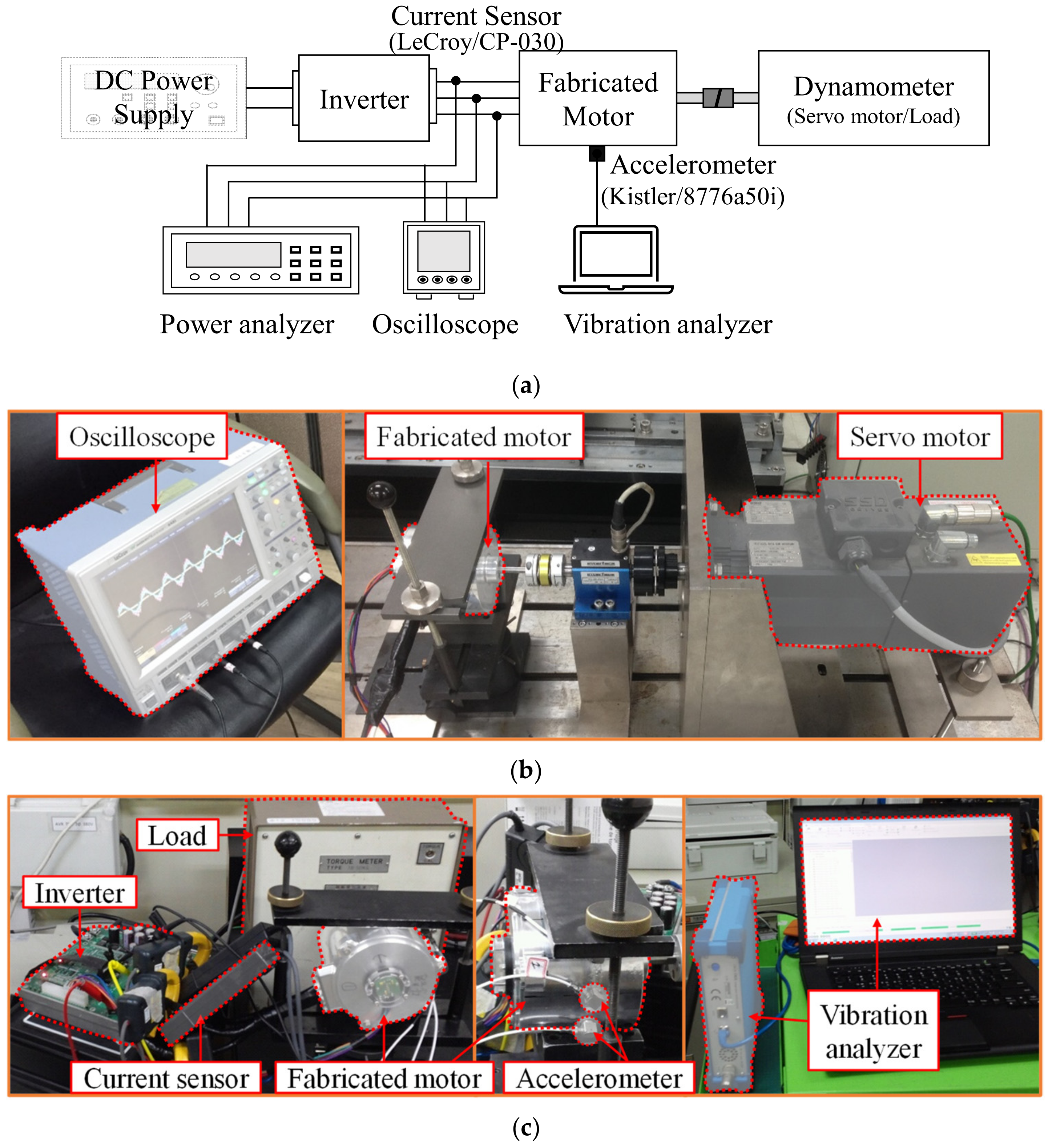
5. Experimental Validation of Vibration Reduction with Four-Layer Winding

In this section, to verify the decrease in displacement by applying the four-layer winding, the experiment is conducted. The motors employing the three proposed winding configurations are fabricated for testing. Figure 13a–c illustrate the experimental setup for the schematic diagram, the no-load test, and the load and vibration test, respectively. In the no-load test, the test motor is mechanically coupled in series with a servo motor, and the back EMF of the three motor types is compared. For the vibration evaluation under load conditions, the test motor is connected to a torque sensor and a load motor, as shown in Figure 13c. An accelerometer (8776A50I, Kistler, Winterthur, Switzerland) is attached to the housing surface of the stator core, aligned along the radial direction of the excitation, to measure vibrations. The sensor position is marked in Figure 13. Vibration signals are acquired using an FFT analyzer (OR35, OROS, Meylan, French), with a sampling frequency of 10 kHz to ensure accurate capture of harmonic components. A Hanning window is applied to the time-domain signals, and Fast Fourier Transform (FFT) is performed to analyze frequency characteristics. The spectra are averaged over 10 repeated measurements to improve signal reliability and reduce background noise.
The no-load test result is illustrated in Figure 14. The fundamental components of the back EMF of the one-layer and two-layer windings are larger by 5.4% and 3.6% than that of the four-layer winding, respectively, which is similar to those expected in Section 4 A. The difference between the FEA and the no-load test of the three motors is 2.5%, 0.8%, and 0.9%, respectively. The no-load test result shows that the three motors are well fabricated.
Next, the load test is performed at the rated point (2 Nm, 2500 rpm). The line-to-line voltage, line current, power factor, and efficiency of the three models were measured through the load test, and the vibration test was also carried out at the same time. Figure 15 shows the load test, the simulation results presented in Table 6, and a comparison between them. The errors between the simulation and test results for the line-to-line voltage and line current are less than 5%, and the differences between the simulation and test values for power factor and efficiency are also less than 5%p. This shows that the simulation results and analysis explained above are verified.
Figure 16 presents the vibration test result of the three motors. As shown in Figure 14, the displacement of the four-layer winding is decreased by 52% and 10% compared with that of the one- and two-layer windings, respectively. Compared with the FEA result (Figure 12), the trend of the decrease in the vibration is the same. Thus, it can be determined that using a four-layer winding is effective in reducing vibration.

6. Conclusions

This paper proposed a four-layer winding method to reduce the vibration of FSCW PMSMs. The sub-harmonic components in the airgap MFD, induced by the armature MMF, contribute significantly to low-order REF, which is the primary source of vibration in FSCW PMSMs. By reducing the winding factor of the armature MMF, the four-layer winding suppresses these sub-harmonics, thereby reducing the resulting vibration.
The electrical and mechanical characteristics of one-layer, two-layer, and four-layer winding configurations were compared through FEA and experimental tests. Both simulation and experimental results demonstrated that the four-layer winding significantly reduced stator displacement and vibration levels compared to the other configurations. These findings validate the effectiveness of the proposed method in mitigating vibration while maintaining electrical performance, making it suitable for applications requiring precise and quiet operation, such as home appliances and robots.
Despite its advantages, the four-layer winding presents practical challenges for large-scale implementation. Specifically, the increased structural complexity and reduced slot fill factor may hinder manufacturability and scalability. In particular, manufacturability constraints can arise for certain pole–slot combinations, where phase belt overlap or coil crossing may become problematic. Additionally, dense winding structures may introduce thermal management concerns due to limited cooling paths. Future work should explore the use of high fill-factor coils—such as rectangular or hairpin winding—to improve packing density, simplify the winding layout, and enable automated, cost-effective manufacturing. In addition, further research is needed to assess the performance of the four-layer winding under varying ratios of field and armature MMFs, as well as its impact on torque, power output, efficiency, and thermal behavior. Beyond FSCW PMSMs, the proposed method may also be extended to other motor types, including ultra-high-speed machines, slotless topologies, and low-noise servo drives, where harmonic suppression and vibration reduction are critical. These investigations will help expand the applicability of the four-layer winding structure to a broader range of high-performance and low-noise electric machines.

Author Contributions

Conceptualization, Y.-H.J. and M.-R.P.; methodology, K.-S.C.; software, S.-H.P.; validation, Y.-H.J.; resources, K.-S.C.; data curation, Y.-H.J.; writing—original draft preparation, Y.-H.J. and D.-M.K.; writing—review and editing, S.-H.P. and M.-R.P.; visualization, D.-M.K.; supervision, M.-R.P.; project administration, D.-M.K.; funding acquisition, S.-H.P. and M.-R.P. All authors have read and agreed to the published version of the manuscript.

Funding

This work was supported by the Soonchunhyang University Research Fund. This work was supported by the Dongguk University Research Fund of 2023 (S-2023-G0001-00095).

Data Availability Statement

The data are contained within the article.

Conflicts of Interest

The authors declare no conflicts of interest.

References

  1. Fan, X.; Zhang, B.; Qu, R.; Li, D.; Li, J.; Huo, J. Comparative Thermal Analysis of IPMSMs with Integral-Slot Distributed-Winding (ISDW) and Fractional-Slot Concentrated-Winding (FSCW) for Electric Vehicle Application. IEEE Trans. Ind. Appl. 2019, 55, 3577–3588. [Google Scholar] [CrossRef]
  2. Chen, H.; Qu, R.; Li, J.; Li, D. Demagnetization Performance of a 7MW Interior Permanent Magnet Wind Generator with Fractional-Slot Concentrated Windings. IEEE Trans. Magn. 2015, 51, 8205804. [Google Scholar] [CrossRef]
  3. EL-Refaie, A.M. Fractional-Slot Concentrated-Windings Synchronous Permanent Magnet Machines: Opportunities and Challenges. IEEE Trans. Ind. Electron. 2010, 57, 107–121. [Google Scholar] [CrossRef]
  4. Abdel-Khalik, A.S.; Ahmed, S.; Massoud, A. Low Space Harmonics Cancelation in Double-Layer Fractional Slot Winding Using Dual Multiphase Winding. IEEE Trans. Magn. 2015, 51, 8104710. [Google Scholar] [CrossRef]
  5. Dutta, R.; Chong, L.; Rahman, M.F. Design and Experimental Verification of an 18-Slot/14-pole Fractional-Slot Concentrated Winding Interior Permanent Magnet Machine. IEEE Trans. Energy Convers. 2013, 28, 181–190. [Google Scholar] [CrossRef]
  6. Wang, J.; Atallah, K.; Zhu, Z.Q.; Howe, D. Modular Three-Phase Permanent-Magnet Brushless Machines for In-Wheel Applications. IEEE Trans. Veh. Technol. 2008, 57, 2714–2720. [Google Scholar] [CrossRef]
  7. Zhou, C.; Huang, X.; Li, Z.; Cao, W. Design Consideration of Fractional Slot Concentrated Winding Interior Permanent Magnet Synchronous Motor for EV and HEV Applictaions. IEEE Access 2021, 9, 64116–64126. [Google Scholar] [CrossRef]
  8. Ahsanullah, K.; Dutta, R.; Rahman, M.F. Analysis of Low-Speed IPMMs with Distributed and Fractional Slot Concentrated Windings for Wind Energy Applications. IEEE Trans. Magn. 2017, 53, 3101710. [Google Scholar] [CrossRef]
  9. Kim, H.-J.; Kim, D.-J.; Hong, J.-P. Characteristic Analysis for Concentrated Multiple-Layer Winding Machine with Optimum Turn Ratio. IEEE Trans. Magn. 2014, 50, 7019504. [Google Scholar] [CrossRef]
  10. Farshadnia, M.; Cheema, M.A.M.; Dutta, R.; Fletcher, J.E. Analytical Modeling of Armature MMF Airgap flux density Considering the Non-Homogeneously Saturated Rotor in a Fractional-Slot Concentrated-Wound IPM Machine. IEEE Trans. Magn. 2017, 53, 8200412. [Google Scholar] [CrossRef]
  11. Farshadnia, M.; Cheema, M.A.M.; Dutta, R.; Fletcher, J.E.; Rahman, M.F. Detailed Analytical Modeling of Fractional-Slot Concentrated-Wound Interior Permanent Magnet Machines for Prediction of Torque Ripple. IEEE Trans. Ind. Appl. 2017, 53, 5272–5283. [Google Scholar] [CrossRef]
  12. Dutta, R.; Rahman, M.F.; Chong, L. Winding Inductances of an Interior Permanent Magnet (IPM) Machine with Fractional Slot Concentrated Winding. IEEE Trans. Magn. 2012, 48, 4842–4849. [Google Scholar] [CrossRef]
  13. Carraro, E.; Bianchi, N.; Zhang, S.; Koch, M. Design and Performance Comparison of Fractional Slot Concentrated Winding Spoke Type Synchronous Motors with Different Slot-Pole Combinations. IEEE Trans. Ind. Appl. 2018, 54, 2276–2284. [Google Scholar] [CrossRef]
  14. Dutta, R.; Pouramin, A.; Rahman, M.F. A Novel Rotor Topology for High-Performance Fractional Slot Concentrated Winding Interior Permanent Magnet Machine. IEEE Trans. Energy Convers. 2021, 36, 658–670. [Google Scholar] [CrossRef]
  15. Chung, S.; Kim, J.; Koo, D.; Woo, B.; Hong, D.; Lee, J. Fractional Slot Concentrated Winding Permanent Magnet Synchronous Machine with Consequent Pole Rotor for Low Speed Direct Drive. IEEE Trans. Magn. 2012, 48, 2965–2968. [Google Scholar] [CrossRef]
  16. Yang, J.; Liu, G.; Zhao, W.; Chen, Q.; Jiang, Y.; Sun, L.; Zhu, X. Quantitative Comparison for Fractional-Slot Concentrated-Winding Configurations of Permanent-Magnet Vernier Machines. IEEE Trans. Magn. 2013, 49, 3826–3829. [Google Scholar] [CrossRef]
  17. Toda, H.; Xia, Z.; Wang, J.; Atallah, K.; Howe, D. Rotor eddy-current loss in permanent magnet brushless machines. IEEE Trans. Magn. 2004, 40, 2104–2106. [Google Scholar] [CrossRef]
  18. Wu, L.; Qu, R.; Li, D. Reduction of Rotor Eddy-Current Losses for Surface PM Machines with Fractional Slot Concentrated Windings and Retaining Sleeve. IEEE Trans. Magn. 2014, 50, 8205704. [Google Scholar] [CrossRef]
  19. Choi, G.; Jahns, T.M. Reduction of Eddy-Current Losses in Fractional-Slot Concentrated-Winding Synchronous PM Machines. IEEE Trans. Magn. 2016, 52, 8105904. [Google Scholar] [CrossRef]
  20. Chaithongsuk, S.; Takorabet, N.; Kreuawan, S. Reduction of Eddy-Current Losses in Fractional-Slot Concentrated-Winding Synchronous PM Motors. IEEE Trans. Magn. 2015, 51, 8102204. [Google Scholar] [CrossRef]
  21. Wang, J.; Patel, V.I.; Wang, W. Fractional-Slot Permanent Magnet Brushless Machines with Low Space Harmonic Contents. IEEE Trans. Magn. 2014, 50, 8200209. [Google Scholar] [CrossRef]
  22. Islam, M.S.; Kabir, M.A.; Mikail, R.; Husain, I. Space-Shifted Wye–Delta Winding to Minimize Space Harmonics of Fractional-Slot Winding. IEEE Trans. Ind. Appl. 2020, 56, 2520–2530. [Google Scholar] [CrossRef]
  23. Alberti, L.; Bianchi, N. Theory and Design of Fractional-Slot Multilayer Windings. IEEE Trans. Ind. Appl. 2013, 49, 841–849. [Google Scholar] [CrossRef]
  24. Alberti, L.; Barcaro, M.; Bianchi, N. Design of a Low-Torque-Ripple Fractional-Slot Interior Permanent-Magnet Motor. IEEE Trans. Ind. Appl. 2014, 50, 1801–1808. [Google Scholar] [CrossRef]
  25. Sun, A.; Li, J.; Qu, R.; Li, D. Effect of Multilayer Windings on Rotor Losses of Interior Permanent Magnet Generator with Fractional-Slot Concentrated-Windings. IEEE Trans. Magn. 2014, 50, 8105404. [Google Scholar] [CrossRef]
  26. Bianchi, N.; Alberti, L.; Barcaro, M. Design and Tests of a Four-Layer Fractional-Slot Interior Permanent-Magnet Motor. IEEE Trans. Ind. Appl. 2016, 52, 2234–2240. [Google Scholar] [CrossRef]
  27. Liu, G.; Zhai, F.; Chen, Q.; Xu, G. Torque Pulsation Reduction in Fractional-Slot Concentrated-Windings IPM Motors by Lowering Sub-Harmonics. IEEE Trans. Energy Convers. 2019, 34, 2084–2095. [Google Scholar] [CrossRef]
  28. Gieras, J.F.; Wang, C.; Lai, J.C. Magnetic fields and radial forces in polyphase motors fed with sinusoidal currents. In Noise of Polyphase Electric Motors, 1st ed.; CRC Press: Boca Raton, FL, USA, 2006; Chapter 2; pp. 21–64. [Google Scholar]
  29. Kim, D.-Y.; Park, M.-R.; Sim, J.-H.; Hong, J.-P. Advanced Method of Selecting Number of Poles and Slots for Low-Frequency Vibration Reduction of Traction Motor for Elevator. IEEE/ASME Trans. Mechatron. 2017, 22, 1554–1562. [Google Scholar] [CrossRef]
  30. Jung, Y.; Park, M.; Lim, M. Asymmetric Rotor Design of IPMSM for Vibration Reduction Under Certain Load Condition. IEEE Trans. Energy Convers. 2020, 35, 928–937. [Google Scholar] [CrossRef]
  31. Lu, W.; Gui, Z.; Ni, J.; Xu, S. Influence of asymmetric-paths winding on electromagnetic force of variable speed pump storage generator-motor. Results Eng. 2024, 21, 101813. [Google Scholar] [CrossRef]
Figure 1. One-layer winding of 10 poles–12 slots: (a) star of slots; (b) winding layout.
Mathematics 13 01603 g001
Figure 2. Two-layer winding of 10 poles–12 slots: (a) star of slots; (b) winding layout.
Mathematics 13 01603 g002
Figure 3. Four-layer winding of 10 poles–12 slots: (a) star of slots; (b) winding layout.
Mathematics 13 01603 g003
Figure 4. Magnetomotive force of single coil with Nc turns.
Mathematics 13 01603 g004
Figure 5. Armature MMF of three models: (a) waveform; (b) harmonic analysis.
Mathematics 13 01603 g005
Figure 6. Configurations of PMSMs with different winding methods: (a) one-layer; (b) two-layer; (c) four-layer. All models use a 10-pole, 12-slot structure for performance comparison.
Mathematics 13 01603 g006
Figure 7. Back EMF characteristics of the three winding methods: (a) no-load phase EMF waveforms at 1000 rpm; (b) harmonic spectra of EMF showing reduced total harmonic distortion (THD) in the four-layer winding.
Mathematics 13 01603 g007
Figure 8. Electromagnetic torque waveforms under rated conditions (2 Nm, 2500 rpm) for each winding method, showing that the four-layer winding results in the lowest torque ripple among the three models.
Mathematics 13 01603 g008
Figure 9. Process of vibration simulation for motor displacement calculation based on electromagnetic and mechanical FEA.
Mathematics 13 01603 g009
Figure 10. Airgap MFD in the airgap at line frequency, waveform (@t = 0), and space-harmonic component by (a) PM; (b) armature MMF, with notable reduction in the 0.2-order harmonic using the four-layer winding.
Mathematics 13 01603 g010
Figure 11. Radial electromagnetic force: (a) Spectral analysis for the three winding methods; (b) magnitude according to vibration order in twice the line frequency.
Mathematics 13 01603 g011
Figure 12. Displacement spectrum obtained from vibration simulation, showing the lowest amplitude at the 2nd-order time-harmonic in the four-layer winding.
Mathematics 13 01603 g012
Figure 13. Experimental setup: (a) schematic; (b) no-load test; (c) load and vibration test.
Mathematics 13 01603 g013
Figure 14. No-load test result: (a) 1-layer; (b) 2-layer; (c) 4-layer.
Mathematics 13 01603 g014
Figure 15. Load test result: (a) line-to-line voltage; (b) line current; (c) power factor; (d) efficiency.
Mathematics 13 01603 g015
Figure 16. Vibration test result.
Mathematics 13 01603 g016
Table 1. Space-harmonic order of airgap MFD by armature MMF for various pole–slot combinations.
PolesSlotsjSpace-Harmonic Order
8981/4, 2/4, 1, 5/4, 7/4, 2, 10/4, …
1221, 2, 4, 5, 7, 8, 10, …
1841/2, 1, 2, 5/2, 7/2, 4, 5, …
4811, 5, 7, 11, 13, 17, 19, …
101251/5, 1, 7/5, 11/5, 13/5, 17/5, 19/5, …
1521, 2, 4, 5, 7, 8, 10, …
6011, 5, 7, 11, 13, 17, 19, …
121821, 2, 4, 5, 7, 8, 10, …
2741/2, 1, 2, 5/2, 7/2, 4, 5, …
7211, 5, 7, 11, 13, 17, 19, …
141271/7, 5/7, 1, 11/7, 13/7, 17/7, 19/7, …
1871/7, 5/7, 1, 11/7, 13/7, 17/7, 19/7, …
2121, 2, 4, 5, 7, 8, 10, …
161881/4, 2/4, 1, 5/4, 7/4, 2, 10/4, …
2421, 2, 4, 5, 7, 8, 10, …
3641/2, 1, 2, 5/2, 7/2, 4, 5, …
Table 2. Vibration order and frequency of REF [30].
ContentsFrequencyVibration Order
Self of PM (μ1 ± μ2)fp(μ1 ± μ2)
Self of armature MMF(n1 ± n2)fp(ν1 ± ν2)
Mutual of the PM and armature MMF(μ ± n)fp(μ ± ν)
Mutual of the PM and stator slot(μ1 ± μ2)fp(μ1 ± μ2) ± kS or p(μ1 ± μ2) ± (k1 ± k2)S
Mutual of the armature MMF and stator slot(n1 ± n2)fp(ν1 ± ν2) ± kS or p(ν1 ± ν2) ± (k1 ± k2)S
Table 3. Vibration order for various pole–slot combinations.
PolesSlotsVibration Order
891, 2, 4, 5, 7, 8, 10, …
124, 8, 16, 20, 28, 32, 40, …
182, 4, 8, 10, 14, 16, 20, …
488, 16, 32, 40, 56, 64, 80, …
10122, 4, 8, 10, 14, 16, 20, …
155, 10, 20, 25, 35, 40, 50, …
6010, 20, 40, 50, 70, 80, 100, …
12186, 12, 24, 30, 42, 48, 60, …
273, 6, 12, 15, 21, 24, 30, …
7212, 24, 48, 60, 84, 96, 120, …
14122, 4, 8, 10, 14, 16, 20, …
182, 4, 8, 10, 14, 16, 20, …
217, 14, 28, 35, 49, 56, 70, …
16182, 4, 8, 10, 14, 16, 20, …
248, 16, 32, 40, 56, 64, 80, …
364, 8, 16, 20, 28, 32, 40, …
Table 4. Winding factor according to number of layers.
ItemHarmonic OrderOne-LayerTwo-LayerFour-Layer
kν cos π ν θ 2 cos π ν θ 2 cos π ν θ 2
kν1 cos π ν θ 2 cos 2 π ν θ 2
k0.20.2590.0670.017
10.9660.9330.901
1.40.9660.9330.901
2.20.2590.0670.017
2.6−0.2590.067−0.017
3.4−0.9660.933−0.901
3.8−0.9660.933−0.901
Table 5. Model specifications.
ContentUnitValue
Motor type-SPMSM
Pole/slot number-10/12
Rotor outer diametermm36
Stator outer diametermm107
Stack lengthmm44
Core material-50PN470
Residual inductionT1.29
Rated speedrpm2500
Rated torqueNm2.0
Rated PowerW524
Drive method-id = 0 control
Table 6. Characteristics of three models.
ContentUnitOne-LayerTwo-LayerFour-Layer
Fundamental component of back EMFVrms1.671.611.56
THD of back EMF%1.50.80.6
Average torqueNm2.02.02.0
Torque ripple%3.80.50.4
Line-to-line voltageVrms9.68.68.1
Line currentArms43.845.246.8
Power factor%80.186.187.8
Efficiency%89.790.690.3
Copper lossW23.324.826.6
Iron lossW21.614.214.2
Mechanical lossW15.215.215.2
Disclaimer/Publisher’s Note: The statements, opinions and data contained in all publications are solely those of the individual author(s) and contributor(s) and not of MDPI and/or the editor(s). MDPI and/or the editor(s) disclaim responsibility for any injury to people or property resulting from any ideas, methods, instructions or products referred to in the content.

