Article

A Throughput Analysis Using a Non-Saturated Markov Chain Model for LTE-LAA and WLAN Coexistence

Department of Computer Science and Engineering, Sejong University, Seoul 05006, Republic of Korea
Mathematics 2025, 13(1), 59; https://doi.org/10.3390/math13010059
Submission received: 6 November 2024 / Revised: 19 December 2024 / Accepted: 26 December 2024 / Published: 27 December 2024

Abstract

:
To address the severe spectrum shortage in mobile networks, the 3rd Generation Partnership Project (3GPP) standardized Long Term Evolution (LTE)-License Assisted Access (LAA) technology. The LTE-LAA system ensures efficient coexistence with other existing unlicensed systems by incorporating listen-before-talk functionality and conducting random backoff operations similar to those in the IEEE 802.11 distributed coordination function. In this paper, we propose an analytical model to calculate the throughput of each system in a scenario where a single LTE-LAA system shares an unlicensed channel with multiple wireless local area network (WLAN) systems. The LTE-LAA system is utilized for supplementary downlink transmission from the LTE-LAA eNodeB (eNB) to LTE-LAA devices. Our proposed analytical model uses a Markov chain to represent the random backoff operations of the LTE-LAA eNB and WLAN nodes under non-saturated traffic conditions and to calculate the impact of the clear channel assessment (CCA) performed by the LTE-LAA eNB. Through numerical results, we demonstrate how the throughput of both the LTE-LAA and WLAN systems is determined by the contention window size and CCA threshold of the LTE-LAA eNB.

1. Introduction

The rapid growth of mobile devices and the rise of diverse mobile applications have led to a severe spectrum shortage in mobile networks. To tackle this issue, the 3rd Generation Partnership Project (3GPP) has standardized Long Term Evolution (LTE)-License Assisted Access (LAA) technology, enabling the use of unlicensed spectrum bands to support downlink transmission in mobile networks [1,2]. LTE-LAA incorporates listen-before-talk functionality to ensure efficient coexistence with other existing unlicensed systems, especially widely deployed wireless local area networks (WLANs). LTE-LAA with the listen-before-talk feature was established as a global standard in 3GPP Release 13 to facilitate coexistence in the unlicensed band [3].
Recently, numerous studies have been conducted to ensure reasonable coexistence between LTE and WLAN systems in unlicensed bands [4,5,6,7,8,9,10,11,12,13,14]. Specifically, several studies have evaluated the performance of LTE-LAA systems employing listen-before-talk and random backoff mechanisms, similar to the IEEE 802.11 distributed coordination function, for accessing unlicensed channels [11,12,13,14]. The studies [11,12] presented simulation results on the throughput of LTE-LAA and WLAN systems under varying congestion conditions, while the study [13] provided experimental results on interference between LTE-LAA and WLAN systems. The study [14] proposed an analytical model to evaluate the throughput of each system under saturated conditions, where both LTE-LAA and WLAN systems consistently have data to transmit.
In this paper, we propose an analytical model to calculate the throughput for each system in a scenario where a single LTE-LAA system, dedicated to downlink transmission, shares an unlicensed channel with multiple WLAN systems. Unlike prior studies on the performance analysis of LTE-LAA and WLAN systems, our study employs a Markov chain approach to model the random backoff operations of LTE-LAA eNodeB (eNB) and WLAN nodes under non-saturated traffic conditions. The Markov chain approach is limited by the need to define LTE-LAA eNB and WLAN node transmissions in discrete timeslots. Nevertheless, it enables a clear and detailed analysis of all sequential random backoff operations in the distributed coordination function of LTE-LAA and WLAN. In addition, we analyze the throughput of LTE-LAA and WLAN systems by integrating the impact of the clear channel assessment (CCA) threshold, which represents the sensitivity level required to detect ongoing transmissions, with Markov chain modeling of random backoff operations. Through numerical results, we demonstrate that the CCA threshold and contention window size of the LTE-LAA eNB play a crucial role in balancing the performance between LTE-LAA and WLAN systems. With a larger contention window size set at the LTE-LAA eNB, the LTE-LAA eNB experienced a longer backoff period, allowing WLAN nodes greater opportunities for channel access. As the CCA threshold set at the LTE-LAA eNB decreased, the LTE-LAA eNB became more sensitive to concurrent WLAN transmissions, which reduced its opportunities for channel access.
The remainder of this paper is organized as follows. Our proposed analytical model is detailed in Section 2. Section 3 discusses the numerical results. Finally, Section 4 concludes this paper.

2. Analysis of LTE-LAA and WLAN System Throughputs

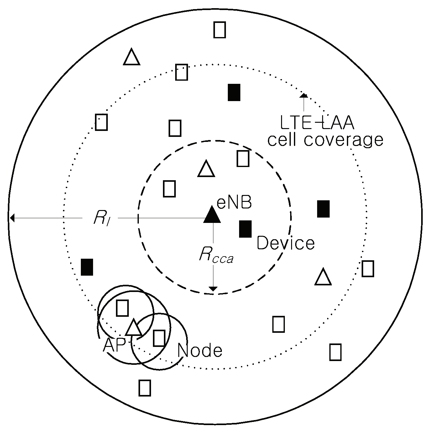
We used a Markov chain model to analyze the throughput of LTE-LAA and WLAN systems in a scenario where a single LTE-LAA system shares the unlicensed spectrum with multiple WLAN basic service sets. Figure 1 shows an LTE-LAA eNB located at the center, with multiple LTE-LAA devices distributed within the coverage area of the LTE-LAA cell, which supports only downlink transmissions from the LTE-LAA eNB to LTE-LAA devices. We define the CCA region as the area where WLAN transmissions are detectable by the LTE-LAA eNB, with R c c a representing its radius. Additionally, we define an interfering region, where WLAN transmissions can interfere with LTE-LAA devices but remain undetectable by the LTE-LAA eNB; R I denotes the distance from the LTE-LAA eNB to the outer boundary of this interfering region.

2.1. Random Backoff Operations in LTE-LAA eNB

LTE-LAA eNB competes with multiple WLAN nodes for channel access by utilizing channel sensing and backoff mechanisms similar to those employed in WLAN systems, as shown in Figure 2.
The LTE-LAA eNB, when handling a new packet, first listens to the target channel to measure the energy level over a duration equal to the distributed inter-frame space (DIFS). If the measured energy level is below the predefined CCA threshold, the LTE-LAA eNB initiates transmission. Otherwise, if the channel is detected as busy, the LTE-LAA eNB continues monitoring until the channel is idle for a DIFS duration. Once the channel is deemed idle, the LTE-LAA eNB generates a random backoff time before transmitting to reduce the probability of collisions with packets transmitted by WLAN nodes. Furthermore, to prevent channel capture, the LTE-LAA eNB must wait for a random backoff interval between two consecutive new packet transmissions, even if the channel is sensed as idle during a DIFS duration. The LTE-LAA eNB operates on a discrete-time backoff scale, where the time following an idle DIFS is divided into fixed-length timeslots. The LTE-LAA eNB is allowed to transmit only at the beginning of each timeslot. For each packet transmission, the LTE-LAA eNB randomly selects a number from the range [ 0 , W 1 ] , where W is referred to as the contention window. The LTE-LAA eNB then counts down the corresponding number of idle timeslots before initiating transmission. The backoff counter decreases as long as the channel is sensed as idle. If a transmission is detected on the channel, the counter is “frozen” and resumes only after the channel has been idle for a DIFS duration. The LTE-LAA eNB initiates transmission when the backoff counter reaches zero.
Figure 2 illustrates an example scenario of the random backoff operations of an LTE-LAA eNB. The LTE-LAA eNB and a WLAN node share the same unlicensed channel. After completing a packet transmission, the LTE-LAA eNB waits for a DIFS duration and selects a backoff counter value of 7 before transmitting the next packet. In this scenario, we assume that the WLAN node transmits a packet in the middle of the timeslot corresponding to a backoff counter value of 5 for the LTE-LAA eNB. As a result of the channel being sensed as busy, the backoff timer is frozen at 5 and resumes decrementing only when the channel is sensed as idle for a DIFS duration. As illustrated in Figure 2, the backoff counter of the LTE-LAA eNB remains frozen during the transmission of a WLAN node, which can cause the time interval between two consecutive timeslot beginnings to be significantly longer than the timeslot size, σ . Specifically, this interval equals the timeslot size, σ , when no other WLAN nodes are transmitting, but it corresponds to the time between two consecutive backoff counter decrements when transmissions from other WLAN nodes are present.

2.2. Markov Chain Model for Random Backoff Operations in LTE-LAA eNB

In this section, referring to [15], we use a Markov chain model to study the random backoff operations of the LTE-LAA eNB, as described in Section 2.1, under non-saturated conditions where packets are not always present in the queue of the LTE-LAA eNB. We then derive the stationary probability τ , representing the probability of the LTE-LAA eNB transmitting a packet during a randomly selected timeslot.
The LTE-LAA eNB shares an unlicensed channel with multiple WLAN nodes. To avoid collisions with packets transmitted by other WLAN nodes, the LTE-LAA eNB generates a random backoff counter before transmitting. Let c ( t ) denote the stochastic process representing the backoff counter for the LTE-LAA eNB. A discrete, integer-based time scale is adopted, where t and t + 1 represent the beginning of two consecutive timeslots. The backoff counter of the LTE-LAA eNB decreases at the beginning of each timeslot.
Assuming non-saturated conditions where the LTE-LAA eNB does not always have packets waiting in its queue for transmission, our Markov chain model, referring to [15], includes two types of states: the post-backoff stage and the backoff stage. The post-backoff stage represents the state where the LTE-LAA eNB has no packets in its queue awaiting transmission, while the backoff stage corresponds to the state where a packet is waiting to be transmitted. Let s ( t ) be the stochastic process indicating whether the LTE-LAA eNB is in the post-backoff stage or the backoff stage at time t. Specifically, if s ( t ) = 1 , it indicates that the LTE-LAA eNB is in the post-backoff stage at time t, and if s ( t ) = 0 , it indicates that the LTE-LAA eNB is in the backoff stage at time t.
The bidimensional process { s ( t ) , c ( t ) } can be represented using a discrete-time Markov chain, as illustrated in Figure 3. The stochastic process s ( t ) , representing the post-backoff stage or the backoff stage, takes values of −1 or 0, while the stochastic process c ( t ) , representing the backoff counter, ranges from 0 to W 1 . Thus, the state space, consisting of a finite set of states, can be expressed as follows:
S = { ( 1 , 0 ) , , ( 1 , k 2 ) , , ( 1 , W 1 ) , ( 0 , 0 ) , , ( 0 , k 2 ) , , ( 0 , W 1 ) }
Let P [ k 1 , k 2 | k 1 , k 2 ] denote the probability of transitioning from state ( k 1 , k 2 ) to state ( k 1 , k 2 ) . In our Markov chain model, since the transition probabilities are independent of the time at which the transition occurs, the transition probability P [ k 1 , k 2 | k 1 , k 2 ] can be expressed as follows:
P [ k 1 , k 2 | k 1 , k 2 ] = P [ s ( t + 1 ) = k 1 , c ( t + 1 ) = k 2 | s ( t ) = k 1 , c ( t ) = k 2 ] , for any t = 0 , 1 ,
In the backoff states, while the medium is sensed as idle, the state ( 0 , k 2 ) is decremented by 1 to ( 0 , k 2 1 ) in each timeslot. However, in the post-backoff states, if there is at least one packet awaiting transmission at the start of a timeslot, the state ( 1 , k 2 ) transitions to the backoff state ( 0 , k 2 1 ) . Otherwise, similar to the backoff states, the state ( 1 , k 2 ) is decremented by 1 to ( 1 , k 2 1 ) . Thus, we have for 1 k 2 W 1
P [ 0 , k 2 1 | 0 , k 2 ] = p 1 = 1 P [ 1 , k 2 1 | 1 , k 2 ] = p 2 = 1 q P [ 0 , k 2 1 | 1 , k 2 ] = p 3 = q
where q is the probability that there is at least one packet awaiting transmission at the start of each backoff counter decrement.
In the backoff state ( 0 , 0 ) , the LTE-LAA eNB transmits; following the transmission, it returns to the post-backoff state with a new k 2 , i.e., state ( 1 , k 2 ) , selected from [ 0 , W 1 ] , provided no collision occurs and there are no packets awaiting transmission in the queue. Thus, this transition probability is
P [ 1 , k 2 | 0 , 0 ] = p 4 = ( 1 p ) ( 1 q ) W
where p is the probability of a collision occurring between transmissions from the LTE-LAA eNB and WLAN nodes within the CCA range. However, if a collision occurs, or if the transmission is successful and there is at least one packet remaining in the buffer, the LTE-LAA eNB reenters the backoff state with a new k 2 chosen within the range [ 0 , W 1 ] .
P [ 0 , k 2 | 0 , 0 ] = p 5 = p W + ( 1 p ) q W
In addition, we consider the state ( 1 , 0 ) , where post-backoff is complete but there are no packets awaiting transmission in the buffer. Suppose a packet arrives in the buffer while in state ( 1 , 0 ) . If the medium is sensed as busy during an additional timeslot, the LTE-LAA eNB enters a new backoff state ( 0 , k 2 ) ; otherwise, it transmits immediately. If a collision occurs following the transmission, the LTE-LAA eNB again enters a backoff state ( 0 , k 2 ) . Therefore, the probability of this transition is
P [ 0 , k 2 | 1 , 0 ] = p 6 = q ( 1 P i d l e ) W + q P i d l e p W
where P i d l e represents the probability that the medium is sensed as idle during a timeslot. If the transmission succeeds without a collision, the LTE-LAA eNB returns to the state ( 1 , k 2 ) , where k 2 is selected from [ 0 , W 1 ] . Thus, we have
P [ 1 , 0 | 1 , 0 ] = p 7 = 1 q + q P i d l e ( 1 p ) W P [ 1 , k 2 | 1 , 0 ] = p 8 = q P i d l e ( 1 p ) W , for 1 k 2 W 1
Let P denote the transition probability matrix of the Markov chain model illustrated in Figure 3. Then, using Equations (3)–(7), we can express the transition probability matrix P as shown in Figure 4.
Let b ( 0 , k 2 ) and b ( 1 , k 2 ) denote the stationary probabilities of being in the states ( 0 , k 2 ) and ( 1 , k 2 ) , representing the backoff and post-backoff states, respectively. Then, these stationary probabilities can be expressed as follows:
b ( 0 , k 2 ) = lim t P [ s ( t ) = 0 , c ( t ) = k 2 ] , b ( 1 , k 2 ) = lim t P [ s ( t ) = 1 , c ( t ) = k 2 ] , for 0 k 2 W 1
Taking into account all stationary state probabilities, we derive the following normalization condition:
k 2 = 0 W 1 b ( 1 , k 2 ) + k 2 = 0 W 1 b ( 0 , k 2 ) = 1
Using Equations (3)–(7), we express all stationary state probabilities in terms of b ( 1 , k 2 ) . Then, by applying the normalization equation in Equation (9), we can further express b ( 1 , k 2 ) in terms of p, P i d l e , q, and W.
A transition into the state ( 1 , W 1 ) from the state ( 1 , 0 ) occurs as described in Equation (7). In addition, a transition into the state ( 1 , W 1 ) from the state ( 0 , 0 ) occurs as described in Equation (4). Thus, the stationary probability of the state ( 1 , W 1 ) is given by
b ( 1 , W 1 ) = b ( 1 , 0 ) q ( 1 p ) P i d l e W + b ( 0 , 0 ) ( 1 p ) ( 1 q ) W
Referring to Equation (3), for 1 k 2 W 2 , we can express b ( 1 , k 2 ) as b ( 1 , k 2 ) = ( 1 q ) b ( 0 , k 2 + 1 ) e + b ( 1 , W 1 ) , while for k 2 = 0 , the relation q b ( 1 , 0 ) = ( 1 q ) b ( 1 , 1 ) + b ( 1 , W 1 ) holds. By straightforward recursion, this leads to q b ( 1 , 0 ) = b ( 1 , W 1 ) · ( 1 ( 1 q ) W ) / q . Thus, using Equation (10), we have
b ( 1 , 0 ) b ( 0 , 0 ) = 1 q q ( 1 p ) ( 1 ( 1 q ) W ) q W P i d l e ( 1 p ) ( 1 ( 1 q ) W )
Using these equations, we determine the first sum in Equation (9),
k 2 = 0 W 1 b ( 1 , k 2 ) = b ( 1 , 0 ) · q W 1 ( 1 q ) W
Referring to Equations (5) and (6), in the same manner as Equation (10), the stationary probability of the state ( W 1 ) is given by
b ( 0 , W 1 ) = b ( 1 , 0 ) · q ( 1 P i d l e ) W + q P i d l e p W + b ( 0 , 0 ) · p W + ( 1 p ) q W
We can express b ( 0 , k 2 ) in terms of b ( 0 , W 1 ) and b ( 1 , W 1 ) because b ( 0 , k 2 ) = b ( 0 , k 2 + 1 ) + b ( 0 , W 1 ) + q b ( 1 , k 2 + 1 ) for 0 k 2 W 2 . Thus, using Equations (10), (11), and (13), the second sum in Equation (9) is
k 2 = 0 W 1 b ( 0 , k 2 ) = b ( 1 , 0 ) · [ q 2 w q + q ( 1 q ) W 1 ( 1 q ) W + ( 1 q ) 2 { 1 ( 1 q ) W 2 } q ( 1 q ) ( W 2 ) 1 ( 1 q ) W + q 2 ( W 1 ) ( W 2 ) 2 { 1 ( 1 q ) W } + q ( W + 1 ) { 1 P i d l e ( 1 p ) } 2 + q ( W + 1 ) [ q W P i d l e ( 1 p ) { 1 ( 1 q ) W } ] { ( 1 p ) q + p } 2 ( 1 q ) ( 1 p ) { 1 ( 1 q ) W } ]
The LTE-LAA eNB attempts transmission in the following two cases: (i) when a packet arrives in the buffer and the medium is sensed as idle in the state ( 1 , 0 ) , and (ii) when the LTE-LAA eNB is in the state ( 0 , 0 ) . Thus, the transmission probability is τ = q P i d l e b ( 1 , 0 ) + b ( 0 , 0 ) . Using Equation (11), it can be expressed as follows:
τ = b ( 1 , 0 ) q 2 W q 2 P i d l e ( 1 p ) ( 1 ( 1 q ) W ) ( 1 p ) ( 1 q ) ( 1 ( 1 q ) W )
where τ can be expressed in terms of p, P i d l e , q, and W from Equations (9), (12), and (14). Thus, given p, P i d l e , q, and W, we can calculate the transmission probability of the LTE-LAA eNB using Equation (15). In Section 2.4, the transmission probability τ is used to calculate the throughputs of both LTE-LAA and WLAN systems.

2.3. Interference Measured at an LTE-LAA Device

It is assumed that the LTE-LAA eNB uses an omnidirectional antenna, as illustrated in Figure 5; its transmission power, denoted by P e , is fixed in accordance with regulations for unlicensed band usage. Let P r x , u represent the received signal power at an LTE-LAA device u from the LTE-LAA eNB, and let P I denote the cumulative interference from concurrent transmissions by multiple WLAN nodes. Then, P r x , u = K r u η P e , where K is a constant and η is the propagation loss exponent [16]. The signal to interference plus noise ratio (SINR) at the LTE-LAA device u can then be obtained as follows:
γ = P r x , u P I + P N
where P N is the noise.
To calculate P I , we approximate the interference from discrete WLAN nodes as a continuous field with an equivalent node density [16,17]. In this model, the continuous field is defined by the density of interfering WLAN nodes, denoted as λ n . Let I b represent the set of WLAN basic service sets in the interfering region, and σ i represent the channel utilization of each WLAN basic service set i. Then, the density is given by λ n = i I b σ i / A I , where A I is the area of the interfering region, calculated as A I = π ( R I 2 R c c a 2 ) [16].
We consider a scenario where an LTE-LAA device experiences interference from transmissions by WLAN nodes located in the interfering region, as shown in Figure 5a. Let ν represent the distance between the LTE-LAA device and an interfering WLAN node. Figure 5b depicts a polar coordinate system centered at the LTE-LAA eNB. Let y be the distance between the LTE-LAA eNB and an infinitesimal element of the interfering region, which is given by
y = α ( R I R c c a ) + R c c a
where α [ 0 , 1 ] is a scaling factor. When α = 0 and α = 1 , the infinitesimal element is located at the boundary of the CCA range and the outer boundary of the interfering region, respectively.
Let θ denote a polar angle in the polar coordinate system; then, given a scaling factor α and a polar angle θ , the distance ν can be obtained as follows:
ν ( α , θ ) = | y r u | ,     for θ = 0 y 2 + r u 2 2 · y · r u · cos θ , for 0 < θ < π y + r u , for θ = π ,
As shown in Figure 5b, an infinitesimal element of the interfering region can be given by
d A I = y · d y d θ
From the equation above, the total number of interfering WLAN nodes contained in the infinitesimal element is given by λ n · d A I = λ n · y · d y d θ ; then, using Equation (18), their interference power is P n K ν ( α , θ ) η · λ n · d A I where P n is the transmit power of a WLAN node. Thus, in the interfering region, the average interference power measured at the LTE-LAA device is
P I 2 λ n P n K · 0 π 0 1 ν ( α , θ ) η · ( R I R c c a ) d α d θ
Here, referring to Equation (17), we use the relation d y = ( R I R c c a ) · d α .
Thus, using Equations (16) and (20), we can calculate the average SINR for each LTE-LAA device, which will then be used to estimate the data rate of the LTE-LAA system in Section 2.4. We adopt the Shannon capacity as the LTE-LAA rate function, allowing us to estimate the LTE-LAA rate as follows [18,19]:
R l a a ( γ ) κ b w · κ c · B log 2 ( 1 + γ / κ s i n r )
where B represents the bandwidth of a subchannel, and κ b w is the system efficiency factor accounting for various system-level overheads. The parameters κ c and κ s i n r together adjust for the SINR implementation efficiency of the modulation and coding schemes [19].

2.4. Throughput of LTE-LAA and WLAN Systems

In this subsection, we analyze the throughput of LTE-LAA and WLAN systems based on the random backoff operations of WLAN nodes and the random backoff operations of the LTE-LAA eNB, as explained in Section 2.2.
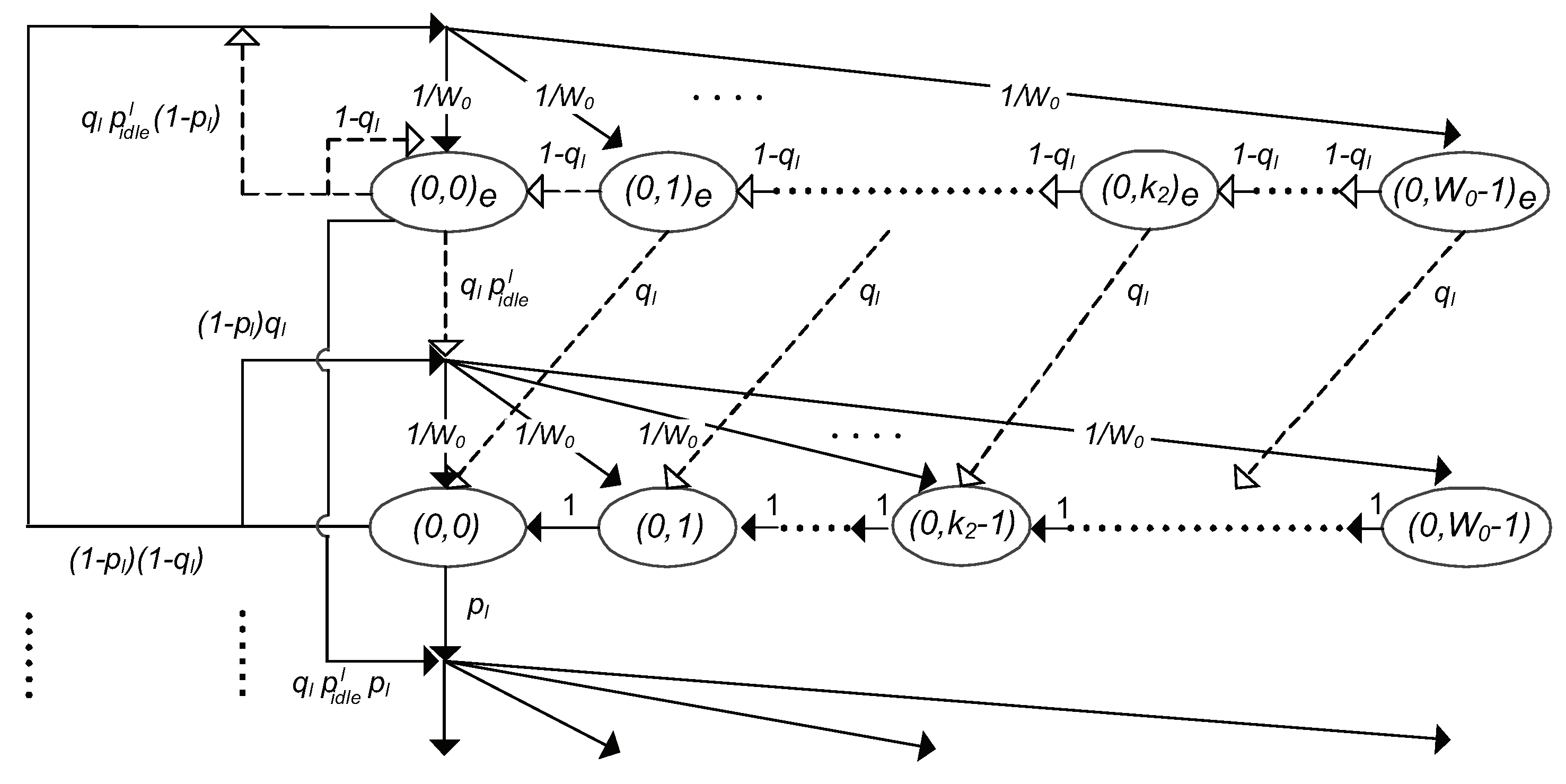
The WLAN nodes employ random backoff operations, similar to those of LTE-LAA eNB described in Section 2.1, to control access to the shared wireless channel. The study in [15] analyzed the random backoff operations of WLAN nodes using a non-saturated Markov chain, with post-backoff and backoff stages denoted as ( 0 , k 2 ) e and ( k 1 , k 2 ) , respectively. Figure 6 illustrates the first two stages of the Markov chain model proposed in [15]. The following notations are used in this subsection:
  • k 1 : Backoff stage number.
  • k 2 : Value of the backoff counter.
  • W 0 : Minimum contention window size.
  • b ( 0 , 0 ) e : Stationary probabilities of being in the post-backoff states ( 0 , 0 ) e .
  • p l : Collision probability of WLAN node l.
  • q l : Probability of at least one packet awaiting transmission in the buffer of WLAN node l in a timeslot.
  • P i d l e l : Probability that WLAN node l senses the medium as idle in a timeslot.
  • τ l : Probability that WLAN node l is attempting transmission in a timeslot.
  • L ( T ) : Set of WLAN nodes located within the CCA ranges of the nodes in the set T, which does not include the nodes in the set T.
  • L : Set of WLAN nodes located in the CCA range of the LTE-LAA eNB.
Then, referring to [15], the transmission probability τ l can be obtained as follows:
τ l = b ( 0 , 0 ) e · q l 2 W 0 ( 1 p l ) ( 1 q l ) ( 1 ( 1 q l ) W 0 ) q l 2 P i d l e l 1 q l
To simplify the analysis, we disregard the hidden-node problem; specifically, we assume that, for any transmitting and receiving pair of WLAN nodes, the receiver can only sense transmissions from WLAN nodes located within the CCA range of the transmitter. Thus, considering the transmissions of both the LTE-LAA eNB and WLAN nodes within the CCA range of transmitter l, the collision probability p l in Equation (22) is given by
1 p l = ( 1 τ ) · l L ( { l } ) ( 1 τ l )
where the transmission probability of the LTE-LAA eNB, τ , can be obtained from Equation (15). Using Equation (23), P i d l e l = 1 p l .
The probability that at least one WLAN node within the CCA range of the LTE-LAA eNB attempts transmission is given by
τ w = 1 l L ( 1 τ l )
The channel usage state may be occupied due to either a successful transmission or a collision among transmissions; otherwise, the medium may be idle. Using Equations (15) and (24), the probability that the LTE-LAA eNB or at least one of WLAN nodes will attempt transmission is
P t r = 1 ( 1 τ ) ( 1 τ w )
The probabilities that the LTE-LAA eNB and the WLAN nodes within the CCA range transmit without collision are, respectively,
P u , s = τ ( 1 τ w ) P w , s = τ w ( 1 p w ) ( 1 τ )
The probability that the transmission from the LTE-LAA eNB is interfered with by transmissions from WLAN nodes within the CCA range is given by
P u , c = τ w · τ
The probability of a collision occurring among transmissions of WLAN nodes within the CCA range is
P w , c = τ w · p w · ( 1 τ )
Suppose that n l WLAN nodes, labeled l 1 , l 2 , , l n l , are attempting transmission in a timeslot. For all these transmissions to succeed, the LTE-LAA eNB must remain idle, each WLAN node must be outside the CCA range of the others, and none of the WLAN nodes in the set L ( l 1 , l 2 , , l n l ) should transmit. Thus, the probability of all these transmissions succeeding is
P s u c c ( T ) = ( 1 τ ) · A ( T ) · l L ( T ) ( 1 τ l )
where T = { l 1 , l 2 , , l n l } and A ( T ) is an indicator function. If each node in T is outside the CCA range of every other node in T, then A ( T ) = 1 ; otherwise, A ( T ) = 0 .
Using Equation (29), the probability that all transmissions succeed when some WLAN nodes located within the CCA range of the LTE-LAA eNB transmit in a timeslot is
P w , s = T L P s u c c ( T ) · l T τ l
Using the equation above, the probability of a collision occurring among transmissions from WLAN nodes located within the CCA range of the LTE-LAA eNB is
P w , c = ( 1 τ ) · ( τ w P w , s )
Let T l a a denote the expected time for a transmission by the LTE-LAA eNB, and let T w , s and T w , c denote the expected times for a successful transmission by a WLAN node and a collision experienced by the WLAN node, respectively. Using P t r , P u , s , P u , c , P w , s , and P w , c in Equations (25)–(28), (30), and (31), respectively, the expected time spent per channel state is
E s = ( 1 P t r ) σ + P u , s T l a a + P w , s T w , s + P u , c · max { T l a a , T w , c } + P w , c T w , c
where σ is the timeslot size.
Let R W denote the data rate of the WLAN system, as defined in the 802.11 standard [20]. The throughput of the WLAN system can then be obtained as follows:
S w = P w , s T w , s d a t a R W E s
Here, T w , s d a t a represents the portion of T w , s during which data is transmitted.
Unlike for the WLAN system, we account for throughput degradation due to collisions to estimate the throughput of the LTE-LAA system. Let P I , i n represent the average interference power caused by WLAN nodes within the CCA range. Then, similarly to Equation (20), we can calculate P I , i n ; however, in this case, y = α · R c c a and d y = R c c a · d α . Thus, P I , i n is given by
P I , i n 2 λ n , i n P n K · 0 π 0 1 ν ( α , θ ) η · R c c a d α d θ
where λ n , i n represents the average number of WLAN nodes transmitting simultaneously within the CCA range. Let γ i n denote the SINR measured during a collision. Then, referring to Equation (16), it is given by γ i n = P r x , u P I + P I , i n + P N . Thus, using Equation (21), the throughput of the LTE-LAA system is
S l a a = T l a a d a t a · { P u , s R l a a ( γ ) + P u , c R l a a ( γ i n ) } E s
Here, T l a a d a t a represents the portion of T l a a during which data is transmitted, and γ denotes the SINR measured when there is no interference from WLAN nodes within the CCA range, which can be calculated using Equation (16). If multiple LTE-LAA devices are present, γ and γ i n are computed as the average SINRs across all LTE-LAA devices.
3. Performance Evaluation

We obtained numerical results for the throughput of each system in a coexistence scenario involving LTE-LAA and WLAN systems. As illustrated in Figure 1, we assumed a scenario for performance evaluation where a single LTE-LAA small cell coexists with multiple WLAN access points (APs) operating at a carrier frequency of 5.8 GHz over a 20 MHz bandwidth. Within the LTE-LAA cell, 10 LTE-LAA devices were uniformly distributed, and within a cell of radius R I , five or fifteen APs were also uniformly located. Each AP was connected to five WLAN nodes. The urban micro non-line-of-sight model for a hexagonal cell layout was used to estimate the path loss [12]. Here, with r representing the distance in meters and f c the carrier frequency in GHz, the path loss was given by P L = 36.7 log 10 ( r ) + 22.7 + 26 log 10 ( f c ) (dB). This yields the corresponding values of K = 10 7.254 and η = 3.67 [18]. The other parameters required for our performance evaluation were as follows: P a = 20 dBm, P s = 17 dBm, P e = 30 dBm, P N = 90 dBm, W 0 = 16 , R I = 40 m, κ b w = 0.6726 , κ c = 0.75 , κ s i n r = 1 , B = 20 MHz, D I F S = 34 μ s, S I F S = 16 μ s, σ = 9 μ s.
The WLAN transmission rate, R W , was set to 72 Mbps, while the rate for LTE-LAA can be calculated using Equation (21). The medium access control and physical layer header sizes were set to 272 bits and 128 bits, respectively. The acknowledgment packet was configured with 336 bits, and the payload size was 12,000 bits. The durations T u , s , T u , c , T w , s , and T w , c were influenced by R W , R U , the sizes of headers, acknowledgments, and payload, as well as DIFS, SIFS, and the propagation delay [21]. The propagation delay was set to 2 μ s.
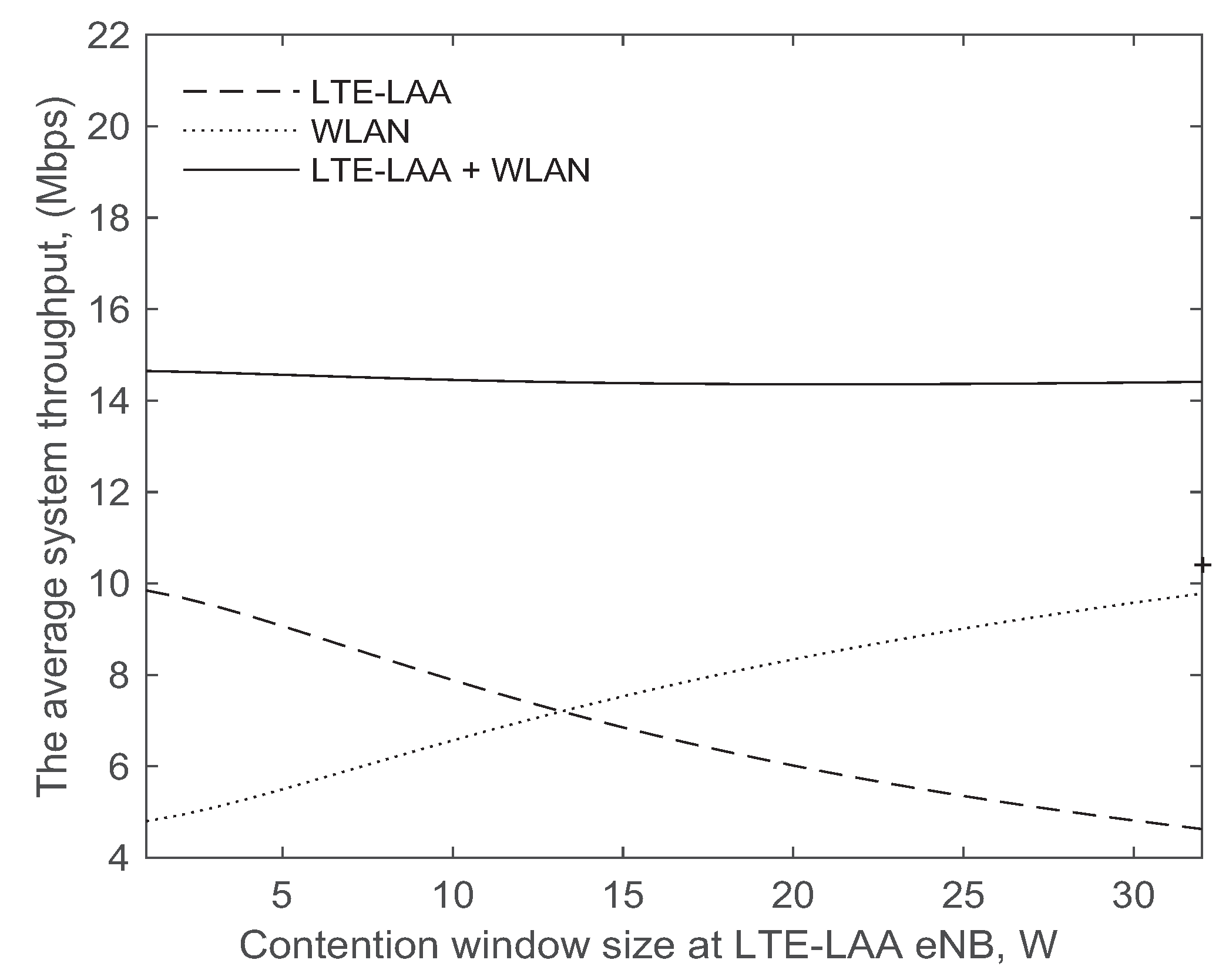
To examine how the contention window size W at the LTE-LAA eNB affects throughput, Figure 7 and Figure 8 present the average throughput versus W for LTE-LAA, WLAN, and the total system (i.e., LTE-LAA+WLAN). It can be observed that, as W increases, the average WLAN throughput increases while the throughput of the LTE-LAA system decreases. This is due to the LTE-LAA eNB experiencing longer backoff durations as W increases, allowing WLAN nodes more frequent access to the channel. Moreover, Figure 7 and Figure 8 illustrate that the average throughput of the LTE-LAA system is lower when fifteen APs are positioned within a cell radius R I , compared to when only five APs are positioned. This is due to the fact that having fifteen APs increases the number of WLAN basic service sets within the CCA range compared to having only five APs.
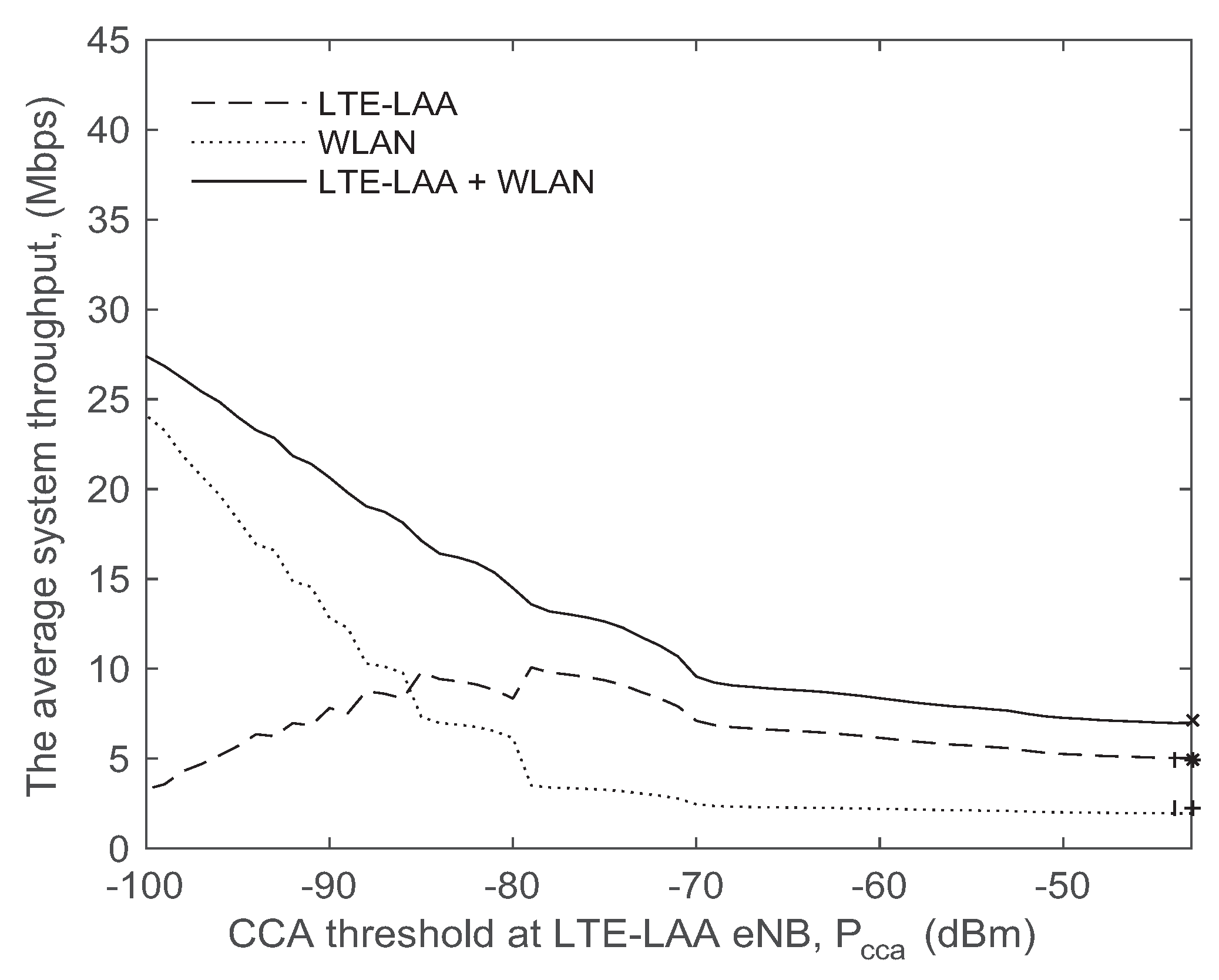
Figure 9 and Figure 10 demonstrate that the average throughput of both LTE-LAA and WLAN systems is highly influenced by the CCA threshold, P c c a , at the LTE-LAA eNB. These figures also reveal distinct operational behaviors between the two systems. For WLAN, the average throughput continuously decreases as P c c a increases. In contrast, the LTE-LAA throughput, shown in Figure 10, increases as P c c a approaches −79 dBm and then gradually declines as P c c a continues to increase. Note that a higher CCA threshold reduces the number of WLAN basic service sets within the CCA range, while the interference experienced by the LTE-LAA device, caused by concurrent transmissions of WLAN nodes in the interfering area, intensifies with an increase in P c c a .

4. Conclusions

We proposed an analytical model using a Markov chain approach to represent the random backoff and CCA operations of LTE-LAA and WLAN systems in a coexistence scenario, thereby enabling throughput calculations for both systems. Numerical results demonstrated that the CCA threshold and contention window size configured at the LTE-LAA eNB were critical in balancing the throughput between LTE-LAA and WLAN systems. A larger contention window size set at the LTE-LAA eNB led to longer backoff periods, thereby increasing channel access opportunities for WLAN nodes. Similarly, a lower CCA threshold at the LTE-LAA eNB heightened its sensitivity to concurrent WLAN transmissions, resulting in fewer channel access opportunities for the LTE-LAA eNB.

Funding

This work was supported by Institute of Information & communications Technology Planning & Evaluation (IITP) under the metaverse support program to nurture the best talents (IITP-2024-RS-2023-00254529) grant funded by the Korea government (MSIT), and this research was supported by the MSIT (Ministry of Science and ICT), Korea, under the ITRC (Information Technology Research Center) support program (IITP-2024-2021-0-01816) supervised by the IITP (Institute for Information & Communications Technology Planning & Evaluation), and this work was supported by the National Research Foundation of Korea (NRF) grant funded by the Korea government (MSIT) (No. NRF-2022R1G1A1012117).

Data Availability Statement

Data are contained within the article.

Conflicts of Interest

The author declares no conflicts of interest.

Abbreviations

Notations for our proposed throughput study.
NotationDescription
P [ k 1 , k 2 | k 1 , k 2 ] Transition probability from state  ( k 1 , k 2 ) to state  ( k 1 , k 2 )
b ( 0 , k 2 ) Stationary probability of being in backoff state ( 0 , k 2 )
b ( 1 , k 2 ) Stationary probability of being in post-backoff state ( 1 , k 2 )
WContention window size of LTE-LAA eNB
P c c a CCA threshold of LTE-LAA eNB
qProbability of at least one packet awaiting transmission at the start of a timeslot
τ Probability that the LTE-LAA eNB is attempting transmission in a timeslot
τ w Probability that WLAN nodes located in the CCA range are attempting transmission in a timeslot
P i d l e Probability that the medium will be sensed as idle in a timeslot
pCollision probability of LTE-LAA eNB
p w Probability of a collision among WLAN nodes located in the CCA range
R I Distance between LTE-LAA eNB and the outer boundary of the interfering region
R c c a Radius of the CCA range of LTE-LAA eNB
R l a a ( · ) Data rate of LTE-LAA eNB
R W Data rate of a WLAN transmission

References

  1. Feasibility Study on Licensed-Assisted Access to Unlicensed Spectrum. Available online: https://portal.3gpp.org/desktopmodules/Specifications/SpecificationDetails.aspx?specificationId=2579 (accessed on 6 December 2024).
  2. Review of Regulatory Requirements for Unlicensed Spectrum. Available online: https://www.3gpp.org/ftp/workshop/2014-06-13_LTE-U/Docs/RWS-140015.zip (accessed on 6 December 2024).
  3. Progress on LAA and Its Relationship to LTE-U and MulteFire. Available online: https://www.qualcomm.com/media/documents/files/laa-webinar-feb-2016.pdf (accessed on 6 December 2024).
  4. Guo, Z.; Li, M.; Krunz, M. Exploiting Successive Interference Cancellation for Spectrum Sharing Over Unlicensed Bands. IEEE Trans. Mobile Comput. 2024, 23, 2348–2455. [Google Scholar] [CrossRef]
  5. Yairnezhad, R.; Ekici, E. A novel scheduling algorithm for LTE on unlicensed bands to ensure fair coexistence with Wi-Fi. Comput. Netw. 2024, 241, 110232. [Google Scholar] [CrossRef]
  6. Zhang, R.; Wang, M.; Cai, L.X.; Zheng, Z.; Shen, X.; Xie, L.L. LTE-unlicensed: The future of spectrum aggregation for cellular networks. IEEE Wirel. Commun. 2015, 22, 150–159. [Google Scholar] [CrossRef]
  7. Ratasuk, R.; Mangalvedhe, N.; Ghosh, A. LTE in unlicensed spectrum using licensed-assisted access. In Proceedings of the 2014 IEEE Globecom Workshops (GC Wkshps), Austin, TX, USA, 8–12 December 2014; pp. 746–751. [Google Scholar]
  8. Jeon, J.; Niu, H.; Li, Q.; Papathanassiou, A.; Wu, G. LTE with listen-before-talk in unlicensed spectrum. In Proceedings of the 2015 IEEE International Conference on Comunication Workshop (ICCW), London, UK, 8–12 June 2015; pp. 2320–2324. [Google Scholar]
  9. Song, Y.; Sung, K.W.; Han, Y. Coexistence of Wi-Fi and Cellular With Listen-Before-Talk in Unlicensed Spectrum. IEEE Commun. Lett. 2016, 20, 161–164. [Google Scholar] [CrossRef]
  10. Ko, H.; Lee, J.; Pack, S. A Fair Listen-Before-Talk Algorithm for Coexistence of LTE-U and WLAN. IEEE Trans. Veh. Technol. 2016, 65, 10116–10120. [Google Scholar] [CrossRef]
  11. Bojovic, B.; Giupponi, L.; Ali, Z.; Miozzo, M. Evaluating Unlicensed LTE Technologies: LAA vs LTE-U. IEEE Access 2019, 7, 89714–89751. [Google Scholar] [CrossRef]
  12. Jeon, J.; Li, Q.C.; Niu, H.; Papathanassiou, A.; Wu, G. LTE in the unlicensed spectrum: A novel coexistence analysis with WLAN systems. In Proceedings of the 2014 IEEE Global Communications Conference, Austin, TX, USA, 8–12 December 2014; pp. 3459–3464. [Google Scholar]
  13. Bhausaheb, E.S.; Vijayabaskar, V. An Opportunistic Coexistence Analysis of LTE and Wi-Fi in Unlicensed 5 GHz Frequency Band. Wirel. Pers. Commun. 2023, 130, 269–280. [Google Scholar] [CrossRef]
  14. Ren, Q.; Zheng, J.; Xiao, J.; Zhang, Y. Performance Analysis of an LAA and WiFi Coexistence System Using the LAA Category-4 LBT Procedure With GAP. IEEE Trans. Veh. Technol. 2021, 70, 8007–8018. [Google Scholar] [CrossRef]
  15. Malone, D.; Duffy, K.; Leith, D. Modeling the 802.11 Distributed Coordination Function in Nonsaturated Heterogeneous Conditions. IEEE/ACM Trans. Netw. 2007, 15, 159–172. [Google Scholar] [CrossRef]
  16. Jeon, J.; Niu, H.; Li, Q.C.; Papathanassiou, A.; Wu, G. LTE in the unlicensed spectrum: Evaluating coexistence mechanisms. In Proceedings of the 2014 IEEE Globecom Workshops (GC Wkshps), Austin, TX, USA, 8–12 December 2014; pp. 740–745. [Google Scholar]
  17. Kelif, J.M.; Coupechoux, M.; Godlewski, P. A Fluid Model for Performance Analysis in Cellular Networks. EURASIP J. Wirel. Commun. Netw. 2010, 2010, 435189. [Google Scholar] [CrossRef]
  18. Liu, F.; Bala, E.; Erkip, E.; Beluri, M.C.; Yang, R. Small Cell Traffic Balancing Over Licensed and Unlicensed Bands. IEEE Trans. Veh. Technol. 2015, 12, 5850–5865. [Google Scholar] [CrossRef]
  19. Mogensen, P.; Na, W.; Kovacs, I.Z.; Frederiksen, F.; Pokhariyal, A.; Pedersen, K.I.; Kolding, T.; Hugl, K.; Kuusela, M. LTE Capacity Compared to the Shannon Bound. In Proceedings of the 2007 IEEE 65th Vehicular Technology Conference—VTC2007-Spring, Dublin, Ireland, 22–25 April 2007; pp. 1234–1238. [Google Scholar]
  20. IEEE Std 802.11-2007; IEEE Standard for Information Technology—Telecommunications and Information Exchange Between Systems—Local and Metropolitan Area Networks—Specific Requirements—Part 11: Wireless LAN Medium Access Control (MAC) and Physical Layer (PHY) Specifications. IEEE Standards: Piscataway, NJ, USA, 2007. Available online: https://standards.ieee.org/ieee/802.11/3605/ (accessed on 6 December 2024).
  21. Martorell, G.; Femenias, G.; Riera-Palou, P. Non-saturated IEEE 802.11 networks. A hierarchical 3D Markov model. Comput. Netw. 2015, 80, 27–50. [Google Scholar] [CrossRef]
Figure 1. An example scenario where LTE-LAA and WLAN systems coexist.
Mathematics 13 00059 g001
Figure 2. Example of the random backoff operations of LTE-LAA eNB.
Mathematics 13 00059 g002
Figure 3. Markov chain model for random backoff operations in LTE-LAA eNB.
Mathematics 13 00059 g003
Figure 4. Transition probability matrix, P, of the Markov chain model for random backoff operations in LTE-LAA eNB.
Mathematics 13 00059 g004
Figure 5. (a) A scenario where an LTE-LAA device is interfered by three WLAN APs and (b) estimation of distance between the LTE-LAA device and an infinitesimal element in a polar coordinate system (the shaded area is the interfering region).
Mathematics 13 00059 g005
Figure 6. Markov chain model for the random backoff operations of a WLAN node.
Mathematics 13 00059 g006
Figure 7. Average throughputs of LTE-LAA and WLAN systems versus W when five APs are positioned within a cell radius R I .
Mathematics 13 00059 g007
Figure 8. Average throughputs of LTE-LAA and WLAN systems versus W when 15 APs are positioned within a cell radius R I .
Mathematics 13 00059 g008
Figure 9. Average throughputs of LTE-LAA and WLAN systems versus P c c a when 5 APs are positioned within a cell radius R I .
Mathematics 13 00059 g009
Figure 10. Average throughputs of LTE-LAA and WLAN systems versus P c c a when 15 APs are positioned within a cell radius R I .
Mathematics 13 00059 g010
Disclaimer/Publisher’s Note: The statements, opinions and data contained in all publications are solely those of the individual author(s) and contributor(s) and not of MDPI and/or the editor(s). MDPI and/or the editor(s) disclaim responsibility for any injury to people or property resulting from any ideas, methods, instructions or products referred to in the content.